1
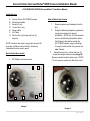
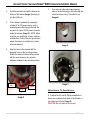
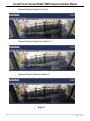
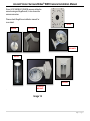
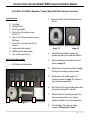
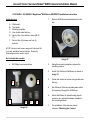
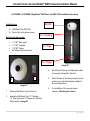
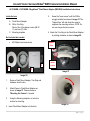
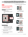
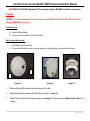
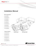
Arecont Vision SurroundVideo® WDR Camera Installation Manual 1|P a g e Arecont Vision SurroundVideo® WDR Camera Installation Manual ® AV12186DN/AV12366DN SurroundVideo Installation Manual Inside the box: A. B. C. D. E. F. G. Arecont Vision AV12186DN camera Mounting template Security L-key 1.5mm Hex L-key Power cable I/O Cable Pack of four (4) screws and four (4) anchors. How to Mount the Camera 1. NOTE: Anchors and screws are good to be used for concrete, wall block and red bricks. Screws by themselves can be used in wood. Not included but needed: #2 Phillips head screw driver Remove camera and hardware from the box. 2. Using the Mounting template, prepare the mounting provisions for camera installation. NOTE: the 19.5mm diameter hole on the Mounting template is where the Ethernet cable will be exiting the AV12186DN camera, align accordingly. If using the side conduit hole, please see step 7 below. 3. Using Security L-key, loosen the four (4) screws securing the dome cover (Image 2). Remove vandal resistant dome cover. NOTE: Do not remove screws from the dome cover. A B C D G E F Image 1 Image 2 1|P a g e Arecont Vision SurroundVideo® WDR Camera Installation Manual 7. 4. Run Ethernet cable through the hole on the bottom of the camera (Image 3) and plug it into the RJ45 port. 5. If the camera is powered by a separate outside AC or DC power source, run the supplied power cable through the hole and connect it to 2-pos. AC/DC power connector inside the camera (Image 3). NOTE: Make sure that your installation of wires complies with Electrical Code of the local government, where the camera is installed and no bare wires are exposed. 6. If you are using the side conduit opening, remove the conduit plug by first removing the socket set screw using 1.5mm Hex L-key (Image 4). Image 4 Align the holes in the camera with the prepared holes on the mounting surface. Attach the camera to the mounting surface with the wood screws or any optional hardware suitable for the mounting surface. HOLE POWER RJ-45 Image 3 Image 5 Adjust Camera Tilt, Pan and Focus: 8. To adjust the tilt, use #2 Phillips screwdriver to loosen two screws on both sides of the Gimbal, no more than two full turns (Image 5) CAUTION: Do not remove the screws! 2|P a g e Arecont Vision SurroundVideo® WDR Camera Installation Manual CAUTION: Make sure the sensor cables are freely moving in cable slot, the correct way to tilt the Gimbal is shown on Image 6. 9. Adjust lens tilt as required and tighten the screw from step 8 10. To adjust the Pan simply rotate the gimbal. The friction ring at the bottom of the gimbal doesn’t require any hardware. NOTE: Grab gimbal by the brackets, not the ball to avoid direct contact with lenses not to damage them or leave fingerprints on glass. 11. To focus each of four lenses, remove the lens cap and focus the lens as shown in Image 7-1 (AV12366DN) and Image 7-2 (AV12186DN) NOTE: the wave washer underneath the lens prevents it from losing focus in vibration. 12. Remove the protective film from the camera dome. NOTE: be cautious not to scratch the vandal-resistant dome cover. 13. Secure the vandal dome cover to the camera as shown in Image 2. CORRECT SLOT POSITION Image 6 Image 7-2 (AV12186DN) Image 7-1 (AV12366DN) 3|P a g e Arecont Vision SurroundVideo® WDR Camera Installation Manual Installation Manual” (found on the CD) for details on Advanced Mode. Camera Installation: 14. Install the AV100 application manager Software as shown in Image 8 (found on the CD). 15. Run the AV100 application manager by double clicking on the icon as shown in Image 9 (found on your desktop). Image 8 Image 9 16. Select “Run” next to “Setup Cameras” from the AV100 application manager as shown in Image 10 and wait for “Arecont Vision Camera Installer” window to appear as shown in Image 11. NOTE 2: Basic Mode: software will automatically discover and change / assign IP address to match PC subnet if they are not locked. NOTE3: User can verify camera model number and FW version of all cameras as shown in Image 11. Image 11 18. Select “Find Cameras” on Arecont Vision Camera Installer as shown in Image 11 19. Confirm all cameras connected to the network switch appear in the upper window. 20. Repeat Step 22 if all of the cameras do not appear in the upper window. Image 10 17. Click “Mode” tab to select desired install mode on Arecont Vision Camera Installer as shown in Image 11. CAUTION: If the software does not find a camera, the software utility may be blocked by ® the anti-virus or Windows firewall. Before turning them off, please consult your IT manager. NOTE 1: Advanced Mode: (Default setting) software will automatically discover but allow manual update of the IP address. See “AV100 4|P a g e Arecont Vision SurroundVideo® WDR Camera Installation Manual NOTE : Double click the camera model on the Camera Installer as shown in Image 12 to access the camera web interface. See “AV Camera Web Page User Manual” (found on the CD) for details on the web interface. Image 12 21. When all cameras appear, select “Save/Exit.” The AV100 application will appear. 22. From the “AV100 Application Manager” menu, select “Run” to view live images. NOTE: See the “AV100 Installation Manual” (found on CD) for details on camera configurations. 5|P a g e Arecont Vision SurroundVideo® WDR Camera Installation Manual Image equalization (exposure reference) instructions: (AV12186DN/AV12366DN) 1. 2. Launch the camera webpage Click “Setting” and select the desired channel to be the cameras “Exposure Reference Channel” (see Image 13). Setting an Exposure Reference Channel will reduce the color and brightness variations among channels. Channel numbers are shown in Image 14. Image 13 NOTE: The default setting for the “Exposure Reference Channel” is “Auto”, which means that each channel is automatically adjusted to provide the best WDR scene. This may cause variations from image to image, however the camera is providing the best image for each channel. When different channels are under different lighting conditions, there will be some color or brightness variation among the channels. See below for an example on how to adjust different reference channels to minimize brightness and color differences. NOTE: Using Exposure Reference Channel Setting may result in abnormal noise which can’t be resolved! 1 4 2 3 Image 14 7|P a g e Arecont Vision SurroundVideo® WDR Camera Installation Manual - Exposure Reference Channel set as “Auto” - Exposure Reference Channel set as Channel “1” - Exposure Reference Channel as Channel “2” Image 15 8|P a g e Arecont Vision SurroundVideo® WDR Camera Installation Manual Since AV12186DN/AV12366DN cameras utilize the same housing as MegaDome®, it also shares the same accessories. Please check MegaDome installation manual for more detail. SV-EBA MD-CMT MD-CRMA MD-WMT2 MD-CAP MD-PMA SV-JBA FOR MD-WMT2 ` Image 16 8|P a g e Arecont Vision SurroundVideo® WDR Camera Installation Manual ® AV12186DN / AV12366DN / MegaDome Pendant Mount (MD-CMT) Installation Instructions Inside the box: 1. Top shield Pendant Mount Mounting template Pack of four (4) machine screws (#8-32 ½”) E. Pack of four (4) small machine screws (M4 8mm) F. Pack of four (4) screws and four (4) anchors G. Large round rubber gasket H. Smaller square rubber gasket I. One double sided hex key Remove Pendant Mount and hardware from the box. A. B. C. D. Image 18 Not included but needed: J. A 2. Using Mounting template, prepare the mounting provisions for camera installation. 3. Place small gasket onto pendant dome as shown in image 18. 4. Attach Dome to Pendant as shown in Image 19 using four machine screws provided. 5. Install large round rubber gasket onto Pendant as shown in image 19. Be sure to align the holes appropriately. 6. Run Ethernet Cable and outside power cable (if necessary) through the Pendant. 7. Attach Pendant to the ceiling using the four wood screws provided or any optional hardware suitable for the mounting surface. 8. For installation of the camera, please reference “Mounting the Camera”. #2 Phillips head screw driver E D F I B H Image 19 G C Image 17 9|P a g e Arecont Vision SurroundVideo® WDR Camera Installation Manual ® AV12186DN / AV12366DN / MegaDome Wall Mount (MD-WMT2) Installation Instructions Inside the box: A. B. C. D. E. F. 1. Remove Wall Mount and hardware from the box. Wall mount Top shield Mounting template One double sided hex key Pack of four (4) machine screws (#8-32 ½”) Pack of four (4) screws and four (4) anchors NOTE: Anchors and screws are good to be used for concrete, wall block and red bricks. Screws by themselves can be used in wood. Not included but needed: Image 21 #2 Phillips head screw driver B A C D Image 20 E 2. Using the mounting template, prepare the mounting surface. 3. Install Top Shield on Wall Mount as shown in image 21. 4. Fasten the socket set screw using double side hex key. 5. Run Ethernet Cable and outside power cable (if necessary) through the Wall Mount. 6. Attach Wall Mount to the wall using drywall screws or any optional hardware suitable for the mounting surface. 7. For installation of the camera, please reference “Mounting the Camera”. F Arecont Vision SurroundVideo® WDR Camera Installation Manual ® AV12186DN / AV12366DN / MegaDome Wall Mount Cap (MD-CAP) Installation Instructions Inside the box: A. B. MD-CAP Wall Mount Cap (MD-CAP) Pack of four (4) machine screws 1 ½” Coupling Not included but needed: 1½” NPT Pipe nipple 1½” NPT Coupling 1½” NPT Flange #2 Phillips head screw driver 1 ½” Pipe 1 ½” Flange Image 23 B A 3. Run Ethernet Cable and outside power cable (if necessary) through the Pendant. 4. Attach Pendant to the ceiling using four wood screws or any optional hardware suitable for the mounting surface 5. For installation of the camera, please reference “Mounting the Camera”. Image 22 1. Remove Wall Mount Cap from the box. 2. Assemble Wall Mount Cap, 1½” Coupling, 1½” Pipe nipple and 1½” Flange as a Pendant Mount shown in image 23. 7|P a g e Arecont Vision SurroundVideo® WDR Camera Installation Manual AV12186DN / AV12366DN / Junction Box Adapter (SV-JBA) for MD-WMT2 Installation Instruction 1. Caution: Remove junction box adapter and hardware from the box SV-JBA should always be used with a wall mount, MD-WMT2, for outdoor installation. SVJBA can only be installed with MD-WMT2 wall mount. It does not work with camera dome, older MD-WMT mount or MD-CMT! Inside the box: A. B. C. D. Junction Box Adapter Pack of four (4) machine screws (#8-32 ½”) One double-sided hex key Pack of four (4) screws and four anchors NOTE: Anchors and screws are good to be used for concrete, wall block and red bricks. Screws by themselves can be used in wood. E. Image 25 2. Remove the conduit plug by first removing the socket set screw using the provided hex key (C). 3. Attach the junction box adapter to the wall using drywall screws or any optional hardware suitable for the mounting surface. 4. Attach the wall mount to junction box adapter then attach cap to the wall mount as shown in Image 25. 5. Connect ¾” NPT Conduit to the junction box adapter. 6. Run Ethernet cable and outside power cable (if necessary) through the Junction Box Adapter and Wall Mount. 7. For installation of the camera, please reference “Mounting the Camera.” Mounting template Not included but needed: #2 Phillips head screwdriver Wall Mount, MD-WMT ¾” NPT Conduit (if necessary) A B C D Image 24 E 12 | P a g e Arecont Vision SurroundVideo® WDR Camera Installation Manual ® AV12186DN / AV12366DN / MegaDome Flush Mount Adapter (MD-FMA) Installation Instructions Inside the box: A. B. C. 5. Flush Mount Adapter White Trim Ring Pack of four (4) machine screws (#8-32 ½”) and one (1) I-Blot Mounting template Screw the “lever screws” until the FMA is snuggly installed, as shown in Image 27. The “Support Arm” will ride down the screw to compress the mounting surface. NOTE: Do not over-torque the lever screws 6. Attach the Trim Ring to the Flush Mount Adapter by rotating clockwise as show in Image 28. Not included but needed: Support Arm #2 Phillips head screw driver C B A D Lever screw Image 27 Image 26 1. Remove Flush Mount Adapter, Trim Ring and hardware from the box 2. Attach Dome to Flush Mount Adapter as shown in Image 27. Please reference “Mounting the Camera”, if needed. 3. Using the Mounting template, cut a hole in surface for mounting. 4. Insert Flush Mount Adapter into the hole. Image 28 13 | P a g e Arecont Vision SurroundVideo® WDR Camera Installation Manual AV12186DN / AV12366DN / Electrical Box Adapter (SV-EBA) Installation Instructions 58. Caution: Attach electrical box adapter to electrical box. SV-EBA can only be installed with MD-WMT2 wall mount. It does not workwith camera dome, older MD-WMT mount or MD-CMT! Inside the box: (Accessory Sold Separately) A. Electrical Box Adapter Pack of four (4) machine screws (#8-32 7/16”) SV-WMT2 Bracket holes Image 30-1 Single gang box Image 30-2 Double gang box A Image 29 Not included but needed: Image 30-3 Square box Common electrical box, such as single gang box, double gang box, or square electrical boxes shown in Image 30-1~4. 56. Remove the electrical box adapter and hardware from the box. 57. Attach the wall mount bracket, SV-WMT2, to the electrical box adapter. Image 30-4 Square box 14 | P a g e Arecont Vision SurroundVideo® WDR Camera Installation Manual ® AV12186DN / AV12366DN / MegaDome Electrical Box Adapter (MD-EBA) Installation Instructions Caution: MD-EBA can only be installed with camera dome, older MD-WMT mount or MD-CMT! MD –EBA doesn’t work with MD-WMT2 wall mount inside the box: B. C. Electrical Box Adapter Pack of four (4) machine screws (M4 10mm) Not included but needed: #2 Phillips head screw driver Common Electrical Box, such as single gang box, double gang box or square electrical box. B A Image 31 Image 32 Image 33 1. Remove Electrical Box Adapter and hardware from the box. 2. Attach Electrical Box Adapter to Electrical Box as shown in Image 32. 3. Attach Dome to Electrical Box Adapter as shown in Image 33. Please reference “Mounting the Camera”, if needed. 15 | P a g e Arecont Vision SurroundVideo® WDR Camera Installation Manual ® AV12186DN / AV12366DN / MegaDome Pole Mount Adapter (MD-PMA) Installation Instructions Inside the box: A. B. C. D. E. 4. Run Ethernet Cable and outside power cable (if necessary) through the Compress Fittings ® and MegaDome Wall Mount. Pole Mount Adapter 2x Compress Fittings 2x Small Steel Straps 2x Large Steel Straps Pack of four (4) machine screws #8-32 5/8” 5. Use the supplied two Steel Straps to attach the Pole Mount Adapter to the pole and tighten the compression screws as shown in Image 36 Not included but needed: 6. Attach Dome to Wall Mount Adapter. Please reference “Mounting the Camera”, if needed. #2 Phillips head screw driver ® MegaDome Wall Mount Adapter 7. Tighten the Compress Fittings to seal the wiring holes. D C E A B Image 35 Image 34 1. Remove Pole Mount Adapter, Compress Fittings, Steel Straps and hardware from the box. 2. Install Compress Fittings to Pole Mount Adapter as shown in Image 35. 3. Attach MegaDome Wall Mount Adapter to Pole Mount Adapter as shown in Image 36 Compression Screws Wall Mount Adapter p ® Image 36 16 | P a g e Arecont Vision SurroundVideo® WDR Camera Installation Manual ® AV12186DN / AV12366DN / MegaDome Corner Mount Adapter (MD-CRMA) Installation Instructions Inside the box: A. B. C. D. 3. Attach Wall Mount Adapter to Corner Mount Adapter as shown in Image 36. Corner Mount Adapter 2x Compression Fittings Pack of four (4) machine screws #8-32 5/8” 2x Packs of four (4) wood screws and four (4) dry wall anchors Not included but needed: Image 38 #2 Phillips head screw driver ® MegaDome Wall Mount Adapter Image 39 B C 4. Run Ethernet Cable and outside power cable (if necessary) through the Compress Fittings ® and MegaDome Wall Mount. 5. Using screws (or other hardware), attach the Corner Mount Adapter to an exterior 90° corner wall. 6. Attach Dome to Wall Mount Adapter. Please reference “Mounting the Camera”, if needed. D A Image 37 1. Remove Corner Mount Adapter, Compress Fitting and hardware from the box. 2. Install Compress Fittings to Corner Mount Adapter as shown in Image 38. 7. Tighten the Compress Fittings to seal the wiring holes. 17 | P a g e Arecont Vision SurroundVideo® WDR Camera Installation Manual ® AV12186DN / AV12366DN / MegaDome I/O Cable Connection Inside the box: A. Table 1 I/O Cable Not included but needed: Electrical Characteristics: Input voltage (V) (measured between + and – terminals) Flat head screw driver Output current (mA) (measured between + and – terminals) Applied Voltage Rage: 0 - 80V A Image 40 1. Run the I/O cable through the hole in the bottom of the camera and plug it into the 4-pin connector as shown in image 41. NOTE: The connector requires certain insertion force. Please, use a flat head screwdriver to push receptacle in. Make sure not to damage wire insulation. ON Min 2.9 Max 6.3 OFF 0 1.3 ON - 50 OFF - 0.1 NOTE: Both the input and the output are electrically isolated from the rest of the camera’s electrical circuitry via general-purpose photo couplers. The input is additionally protected with a serial 250 Ohm resistor, and a debouncing circuit. Duration of any input signal should be at least 5 ms to comply with the requirements of the de-bouncing circuit. Table 2 Orange OUT + Yellow OUT – White IN + Black IN - Image 38 18 | P a g e Arecont Vision SurroundVideo® WDR Camera Installation Manual 19 | P a g e