1
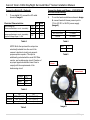
Arecont Vision H.264 Day/Night SurroundVideo® Series Installation Manual ® H.264 Day/Night SurroundVideo Installation Manual Inside the box: A. B. C. D. E. F. ® Arecont Vision SurroundVideo camera Mounting template RJ45 female to female coupler Hex key Security L-key Pack of four (4) wood screws and four (4) dry wall anchors Mounting the Camera: 1. Remove camera and hardware from the box. 2. Using the mounting template, prepare the mounting provisions for camera installation. ® NOTE: Since SurroundVideo series ship with both surface mount and in-ceiling mount, the mounting template takes both into consideration. Not included but needed: #1 Phillips head screwdriver #2 Phillips head screwdriver Flat head screwdriver ( for side conduit opening) B A C D E 3. Using security L-key, loosen the four (4) screws securing the dome cover (Image 2). Remove vandal resistant dome cover. NOTE: Do not remove screws from the dome cover. F Image 1 Image 2 1|P a g e Arecont Vision H.264 Day/Night SurroundVideo® Series Installation Manual 4. If using in-ceiling mount, please use #2 Phillips head screwdriver to loosen the four (4) machine screws (Image 3) and remove inceiling mount housing from surface mount housing. (Image 4) In-Ceiling Mount NOTE 1: The above removed screws are also used to attach the camera with in-ceiling mount housing to the pendant mount (Image 5) and wall mount (Image 6). Do not disregard. Image 4 NOTE 2: The in-ceiling mount only can be attached on hard ceilings including wood, plastic, metal and concrete. Surface Mount NOTE 3: For use in a false ceiling, a flush mount adapter kit must be used. Screws Pendant Mount Image 5 Wall Mount Image 3 Image 6 2|P a g e Arecont Vision H.264 Day/Night SurroundVideo® Series Installation Manual Connecting External Power: (Optional) 5. If you are using the side conduit opening on the surface mount, remove the conduit plug by first removing the socket set screw using the provided Allen key (Image 7) and remove the conduit plug using a flat screwdriver. 6. If the camera is powered by an outside power supply, 12~20VDC or 24VAC, connect the power cable shown in Image 8. Red Black Note: the conduit fits ¾” NPT standard + – Table 1 NOTE: Make sure that your installation of wires complies with Electrical Code of the local government where the camera is installed and no bare wires are exposed. RJ45 Connector Heater & Blower Power input Image 7 Digital I/O connector Conduit Plug External camera Power input Image 8 3|P a g e Arecont Vision H.264 Day/Night SurroundVideo® Series Installation Manual Connecting Digital I/O: (Optional) 7. Connecting Heater and Blower : (AV8185DN-HB and AV8365DN-HB only) To use digital I/O, connect the I/O cable shown in image 8. Electrical Characteristics: ON OFF ON Input voltage (V) (measured between + and – terminals) Output current (mA) (measured between + and – terminals) Applied Voltage Rage: 0 - 80V OFF Min 2.9 0 - 8. Max 6.3 1.3 50 0.1 To run the heater and blower shown in Image 8, connect heater & blower power input to 12V to 20V DC or 24VAC power supply. (Image 9). Power input DC12V to 20V AV24V Power consumption 11 Watts 13 Watts Table 4 Table 2 NOTE: Both the input and the output are electrically isolated from the rest of the camera’s electrical circuitry via generalpurpose photo couplers. The input is additionally protected with a serial 250 Ohm resistor, and a debouncing circuit. Duration of any input signal should be at least 5 ms to comply with the requirements of the debouncing circuit. Red Black + – Table 5 Blower Heater board Orange Yellow White Black OUT + OUT – IN + IN - Table 3 Heater Blower Blower On 17C° (62.6 °F) 10C° (50°F) 50C° (122 °F) Table 6 Off 30 °C (86 °F) 15 °C (59 °F) 45 °C (113°F) Dual power board Image 9 4|P a g e Arecont Vision H.264 Day/Night SurroundVideo® Series Installation Manual 9. Align the holes in the camera with the prepared holes on the mounting surface. Attach the camera with in-ceiling mount housing to the surface mounting housing shown in Image 4. 10. To insert camera with in-ceiling mount into hard ceiling with the wood screws or any optional hardware suitable for the mounting surface shown in Image 10 Adjusting Tilt, Pan and Focus: 10. Power on camera to adjust tilt, pan and focus. 11. To adjust the pan, use a #2 Phillips screwdriver to loosen both screws on the sides of the plastic gimbal bracket as shown in Image 12 and Image 13. 12. Adjust the pan as required and tighten the screw from step 11 shown in image 14. Set Screws Wood Screws Image 12 . Image 13 Image 10 Note: Use Flush Mount Adapter for false ceiling tile installation. (Image 11) Please refer to Flush Mount Adapter Installation Instructions on page10. Flush Mount Adapter Image 11 360° Image 14 5|P a g e Arecont Vision H.264 Day/Night SurroundVideo® Series Installation Manual 13. To adjust the tilt, use a #2 Phillips screwdriver to loosen both screws on the sides of the plastic gimbal bracket 1/4 turn (Image 15 and 16). CAUTION: Do not remove the screws! 14. Adjust lens tilt as required and tighten the screws from step 13 shown in image 17. 100° NOTE: the camera has 2-Axis gimbal with 360° pan and 100° tilt for easy and accurate positioning. Image 17 Image 15 15. To adjust focus, loosen set screw on each lens as shown in Image 18. 16. Adjust lens focus as required and tighten the screws from step 15. Set Screws Set Screws Image 16 Image 18 6|P a g e Arecont Vision H.264 Day/Night SurroundVideo® Series Installation Manual Adjusting Each Sensor Tilt : ( AV8365DN only) NOTE: Each sensor tilt angle can be adjusted by +/- 10° to remove the dead spot at dome bottom or at the horizon. 15. To adjust each sensor tilt angle, use a #1 Philips screwdriver to turn set screws, shown in Image 19 and Image 20. 16. Remove the protective film from the camera dome. NOTE: be careful not to scratch the vandal dome cover. 17. Day/Night Switcher +/- 10° +/- 10° Secure the vandal dome cover to the camera. NOTE 1: Day/Night switcher per sensor in both AV8185DN and AV8365DN shown in Image 19. Set Screws Image 19 NOTE 2: All Day/Night switchers simultaneous switchover, based on the least (or greatest) illuminated sensor. Image 20 7|P a g e Arecont Vision H.264 Day/Night SurroundVideo® Series Installation Manual ® H.264 Day/Night SurroundVideo Pendant Mount SV-CMT Installation Instructions Inside the box: A. B. C. D. E. F. Pendant pole Top shield Pendant Mount One double sided hex key Pack of four (4) wood screws and four (4) dry wall anchors Mounting template Not included but needed: Image 22 #2 Phillips head screw driver A B C Image 23 18. Remove Pendant Mount and hardware from the box. 19. Using the Mounting template, prepare the mounting provisions for camera installation. 20. Connect top shield, pendant pole and mount together as shown in Image 22. NOTE: The thread size of top shield, pendant pole and mount is 1.5” NPT. D E Image 21 21. Attach pendant mount to the ceiling using the four wood screws provided or any optional hardware suitable for the mounting surface. 22. Run Ethernet Cable and outside power cable (if necessary) through the Pendant. 23. For installation of the camera shown in Image 23, please reference “Mounting the Camera”. F 8|P a g e Arecont Vision H.264 Day/Night SurroundVideo® Series Installation Manual ® H.264 Day/Night SurroundVideo Wall Mount SV-WMT Installation Instructions Inside the box: A. B. C. D. E. Top shield Wall mount One double sided hex key Pack of four (4) wood screws and four (4) dry wall anchors Mounting template Not included but needed: Image 25 #2 Phillips head screw driver B A Image 26 24. Remove Wall Mount and hardware from the box. 25. Using the Mounting template, prepare the mounting surface. 26. Connect top shield and wall mount as shown in Image 25. NOTE: The thread size for Top shield, pendant pole and mount is 1.5” NPT. C D E 27. Run Ethernet Cable and outside power cable (if necessary) through the Wall Mount. 28. Attach Wall Mount to the wall using drywall screws or any optional hardware suitable for the mounting surface. 29. For installation of the camera shown in image 26, please reference “Mounting the Camera”. Image 24 9|P a g e Arecont Vision H.264 Day/Night SurroundVideo® Series Installation Manual ® H.264 Day/Night SurroundVideo Flush Mount Adapter Installation Instructions In-Ceiling mount Inside the box: A. B. C. D. E. White Trim Ring Flange Plate Top Plate Mounting template Pack of six (6) set screws, three (3) support arms , three (3) lever screws, three (3) screw nuts and caps and one (1) I-Blot Not included but needed: A Flange Plate Set Screws Image 28 #2 Phillips head screw driver B C D E Top Plate Image 27 30. Remove White Trim Ring, Flange Plate, Top Plate and hardware from the box 31. Attach Flange Plate to in-ceiling mount with 3 set screws as shown in Image 28. 32. Attach Top Plate to in-ceiling mount with other 3 set screws as shown in Image 29. 33. Insert each lever screw into Flange Plate, support arm, Top Plate, screw nuts and caps as shown in Image 30. Image 29 Screw Nut and Cap Arm Support Arm Lever Screw Image 30 10 | P a g e Arecont Vision H.264 Day/Night SurroundVideo® Series Installation Manual 34. Using the Mounting template, cut a hole in surface for mounting. 35. Insert Flush Mount Adapter into the hole. 36. Screw the “lever screws” until the flush mount is snuggly installed, as shown in Image 31. The “Support Arm” will ride down the screw to compress the mounting surface. (Image 32) Support Arm NOTE: Do not over-torque the lever screws 37. 38. For installation of the camera shown in image 33, please reference “Mounting the Camera”. Lever Screw White Trim Ring Image 32 Attach the Trim Ring to the Flush Mount Adapter by rotating clockwise as show in Image 34. Image 33 Lever Screws Image 31 Image 34 11 | P a g e Arecont Vision H.264 Day/Night SurroundVideo® Series Installation Manual ® H.264 Day/Night SurroundVideo Pole Mount Adapter Installation Instructions Inside the box: A. B. C. D. E. 41. Pole Mount Adapter 2x Compress Fittings 2x Small Steel Straps 2x Large Steel Straps Pack of four (4) machine screws 42. Run Ethernet Cable and outside power cable (if necessary) through the Compress Fittings and SV-WMT, Wall Mount Adapter. 43. Use the supplied two Steel Straps to attach the Pole Mount Adapter to the pole and tighten the compression screws (Image 37). Not included but needed: Attach SV-WMT, Wall Mount Adapter, to Pole Mount Adapter as shown in Image 37. #2 Phillips head screw driver SV-WMT, Wall Mount Adapter 44. Attach camera with in-ceiling mount to Wall Mount Adapter. Please reference “Mounting the Camera”, if needed. 45. Tighten the Compress Fittings to seal the wiring holes. D C E A B Image 35 Image 36 ® NOTE: H.264 Day/Night SurroundVideo and MegaDome™ share same pole mount adapter, MD-PMA. 39. Remove Pole Mount Adapter, Compress Fittings, Steel Straps and hardware from the box. 40. Install Compress Fittings to Pole Mount Adapter as shown in Image 36. SV-WMT, Wall Mount Adapter p Compression Screws Image 37 12 | P a g e Arecont Vision H.264 Day/Night SurroundVideo® Series Installation Manual ® H.264 Day/Night SurroundVideo Corner Mount Adapter Installation Instructions Inside the box: A. B. C. D. Corner Mount Adapter 2x Compression Fittings Pack of four (4) machine screws 2x Packs of four (4) wood screws and four (4) dry wall anchors 47. Install Compress Fittings to Corner Mount Adapter as shown in Image 39. 48. Attach Wall Mount Adapter to Corner Mount Adapter as shown in Image 40. Not included but needed: #2 Phillips head screw driver MegaDome™ Wall Mount Adapter Image 39 49. B C D A Image 38 ® NOTE: H.264 Day/Night SurroundVideo and MegaDome™ share same corner mount adapter, MD-CRMA. 46. Image 40 Run Ethernet Cable and outside power cable (if necessary) through the Compress Fittings and MegaDome™ Wall Mount. 50. Using the screws provided (or other hardware) attach the Corner Mount Adapter to an exterior 90° corner wall. 51. Attach camera with in-ceiling mount to Wall Mount Adapter. Please reference “Mounting the Camera”, if needed. 52. Tighten the Compress Fittings to seal the wiring holes. Remove Corner Mount Adapter, Compress Fitting and hardware from the box. 13 | P a g e Arecont Vision H.264 Day/Night SurroundVideo® Series Installation Manual ® H.264 Day/Night SurroundVideo Electrical Box Adapter Installation Instructions Inside the box: A. B. Electrical Box Adapter Pack of four (4) machine screws Not included but needed: #2 Phillips head screw driver Common Electrical Box, such as single gang box, double gang box, or square electrical boxes shown in Image 42-1~4. Image 42-1 Single gang box A Attach to surface mount, wall mount or pendant mount Image 42-2 Double gang box Image 41 NOTE: H.264 Day/Night SurroundVideo® and MegaView™ share same Electrical Box Adapter, MV-EBA. 50. Remove Electrical Box Adapter and hardware from the box. 51. Attach H.264 Day/Night SurroundVideo® surface mount, wall mount or pendant mount to Electrical Box Adapter. (Image 41) 52. Attach Electrical Box Adapter to Electrical Box as shown in Image 42-1~4. Image 42-3 Square box Image 42-4 Square box 14 | P a g e R. 12 .10