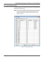
1
Part D301648X012 July 2015 Liquid Allocation Program for Continuous Flow (for FloBoss™ 107 Flow Managers) User Manual Remote Automation Solutions Liquid Allocation Program for Continuous Flow User Manual Revision Tracking Sheet July 2015 This manual may be revised periodically to incorporate new or updated information. The revision date of each page appears at the bottom of the page opposite the page number. A change in revision date to any page also changes the date of the manual that appears on the front cover. Listed below is the revision date of each page (if applicable): Page All pages All pages Initial release ii Revision July-15 May-11 Sep-09 Rev. July-15 Liquid Allocation Program for Continuous Flow User Manual Contents Page Chapter 1 – Introduction 1 1.1 Scope and Organization........................................................................................................ 1 1.2 Product Overview .................................................................................................................. 2 1.3 Program Requirements ......................................................................................................... 3 Chapter 2 – Installation 5 2.1 Installing the License Key ..................................................................................................... 5 2.2 Downloading the Program .................................................................................................... 7 Chapter 3 – Configuration 11 3.1 Liquid Preferences Screen .................................................................................................. 12 3.2 Liquid Products Screen ....................................................................................................... 14 3.2.1 Liquid Products – Product Definition Tab .............................................................. 16 3.2.2 Liquid Products – Advanced Tab ........................................................................... 18 3.3 Liquid Meters Screen .......................................................................................................... 20 3.3.1 Liquid Meters – General Tab ................................................................................. 21 3.3.2 Liquid Meters – Inputs Tab .................................................................................... 23 3.3.3 Liquid Meters – Advanced Tab .............................................................................. 26 3.3.4 Liquid Meters – Alarms Tab ................................................................................... 29 3.3.5 Liquid Meters – Flow Rates Tab ............................................................................ 31 3.3.6 Liquid Meters – Flow Totalizers Tab ...................................................................... 34 3.3.7 Liquid Meters – Densities Tab ............................................................................... 37 3.3.8 Liquid Meters – Day/Month Totalizers Tab ............................................................ 41 3.4 Liquid Density Interfaces Screen ........................................................................................ 44 3.4.1 Liquid Density Interfaces – General Tab ............................................................... 46 3.4.2 Liquid Density Interfaces – Inputs Tab................................................................... 48 3.4.3 Liquid Density Interfaces – Micro Motion Constants Tab ...................................... 50 3.4.4 Liquid Density Interfaces – UGC Constants Tab ................................................... 52 3.4.5 Liquid Density Interfaces – Alarms Tab ................................................................. 54 3.5 Saving the Configuration ..................................................................................................... 56 4 – Reference 59 4.1 Density Ranges for Liquid Product Types........................................................................... 60 4.2 Liquid Allocation History ...................................................................................................... 62 4.2.1 Typical History Setup ............................................................................................. 63 4.3 Point Type 22: Liquid Preference Parameters .................................................................... 65 4.4 Point Type 23: Liquid Product Parameters ......................................................................... 68 4.5 Point Type 25: Liquid Meter Parameters ............................................................................ 70 4.6 Point Type 26: Density Interface Parameters ..................................................................... 97 Rev. July-15 Contents iii Liquid Allocation Program for Continuous Flow User Manual [This page is intentionally left blank.] iv Rev. July-15 Liquid Allocation Program for Continuous Flow User Manual Chapter 1 – Introduction This chapter describes the structure of this manual and presents an overview of the Liquid Allocation Program for Continuous Flow for the FloBoss 107 (FB107). 1.1 Scope and Organization This document is the user manual for the Liquid Allocation Program for Continuous Flow (1LK-7) for use in the FB107, and the user manual for the Liquid Allocation Program for Continuous Flow (QER 10Q006) for use in the FB107 with Measurement Canada firmware. Notes: The standard version of this program (1LK-7) only works with the standard version of FB107 firmware. The Measurement Canada version of this program (QER 10Q006) only works with the Measurement Canada version of FB107 firmware. This manual describes how to download and configure this program (referred to as the “Liquid Allocation program” or “the program” throughout the rest of this manual). You access and configure this program using ROCLINK™ 800 Configuration Software (version 1.80 or greater) loaded on a personal computer (PC) running Windows® 8 or Windows 7 (32 or 64-bit). The sections in this manual provide information in a sequence appropriate for first-time users. Once you become familiar with the procedures and the software running in a FB107, the manual becomes a reference tool. This manual has the following major sections: Chapter 1 – Introduction Chapter 2 – Installation Chapter 3 – Configuration Chapter 4 – Reference This manual assumes that you are familiar with the FB107 and its configuration. For more information, refer to the following manuals: Rev. July-15 FloBoss 107 Flow Manager Instruction Manual (Form A6206) ROCLINK 800 Configuration Software User Manual (for FB107) (Form A6217) Introduction 1 Liquid Allocation Program for Continuous Flow User Manual 1.2 Product Overview The Liquid Allocation program allows a FB107 to interface with up to two meter runs passing liquid hydrocarbon fluids or water. These meter runs are in addition to the meter runs provided by the FB107 Application Firmware. The flowing densities (and optionally, base densities) of the liquid hydrocarbon or water are calculated based on temperatures and pressures using one or more of the following standards: API Standard 2540 [Chapter 11.1] (1980) Volume X, Reaffirmed, October 1993. The Institute of Petroleum, Petroleum Measurement Paper No. 3, October, 1988. API Chapter 11.2.1 – Compressibility Factors for Hydrocarbons: 0 – 90 Degrees API Gravity Range (1st Edition, August 1984), Reaffirmed, May 1996. API Chapter 11.2.2 – Compressibility Factors for Hydrocarbons: 0.350 – 0.637 Relative Density (60°F/60°F) and -50°F to 140°F Metering Temperature (2nd Edition, October 1986). API Chapter 11.2.1M – Compressibility Factors for Hydrocarbons: 638 – 1074 Kilograms per Cubic Metre Range (1st Edition, June, 1984), Reaffirmed, May 1996. API Chapter 11.2.2M – Compressibility Factors for Hydrocarbons: 350 – 637 Kilograms per Cubic Metre Density (15°C) and -46°C to 60°C Metering Temperature (1st Edition, October 1986), Reaffirmed, March, 1997. API MPS (Manual of Petroleum Measurement Standards) Chapter 11 – Physical Properties Data Section 1, Temperature and Pressure Volume Correction Factors for Generalized Crude Oil, Refined Products, and Lubricating Oils, May 2004. Gas Processors Association (GPA) TP-27, Temperature Correction for the Volume of NGL and LPG, Section 5, January, 2005. API MPS (Manual of Petroleum Measurement Standards) Chapter 11 – Physical Properties Data, Section 4 – Properties of Reference Materials, Part 1 – Density of Water and Water Volumetric Correction Factors for Water Calibration of Volumetric Provers, First Edition, December 2003. Meter types can be either differential or linear. The calculation standard used for differential meters is ISO5167. The calculation used for linear meters is based on AGA Report No. 11. Volume and mass flow rates and totals are calculated and stored for both meter types. The program uses user-defined point types for storing the calculated flow rates and accumulations. The program’s user-defined point types are also the location where the configuration parameters reside. The Liquid Allocation program also supports up to two liquid density interface points. The liquid density interface points allow for manual density inputs; density inputs from densitometers; frequency inputs from a 2 Introduction Rev. July-15 Liquid Allocation Program for Continuous Flow User Manual Micro Motion (or Solartron) 7830/40 or 7835/45/46/47; and UGC densitometers. The density value determined from the density input is referred to as the observed density. The base density of the liquid hydrocarbon passing through a meter can be specified to be calculated from the observed density. 1.3 Program Requirements You download the Liquid Allocation program to—and then run it from— the Flash and RAM memory on the FB107 with firmware version 1.30 (or greater). Because the program is larger than 64K, it occupies two user C program numbers (1 & 2). Download and configure the program using ROCLINK 800 Configuration software version 1.84 (or greater). The downloadable program is: File Name Target Unit/ Version User Defined Points (UDP) Flash Used (in bytes) DRAM Used (in bytes) ROCLINK 800 Version Display Number LiquidAlloc_1.bin (1LK-7) FB107 1.30 22, 23, 25, 26 94,560 32,768 1.84 23, 24, 26, 27 LiquidAlloc_1.bin (QER 10Q006) FB107 with MC Firmware 1.00 22, 23, 25, 26 94,560 32,768 1.84 23, 24, 26, 27 Note: You must connect a PC to the FloBoss’s LOI port before starting the download. For information on viewing the memory allocation of user programs, refer to the ROCLINK 800 Configuration Software User Manual (for FB107) (Form A6217). Rev. July-15 Introduction 3 Liquid Allocation Program for Continuous Flow User Manual [This page is intentionally left blank.] 4 Introduction Rev. July-15 Liquid Allocation Program for Continuous Flow User Manual Chapter 2 – Installation This section provides instructions for installing the Liquid Allocation program into the FB107. Read Section 1.3 of this manual for program requirements. Note: The program and license key can be installed in any order. The manual shows the installation of the license key first. 2.1 Installing the License Key A license key (1LK-7) is required to use the Liquid Allocation program. To install a USB key-based license on the FB107: 1. Insert the USB license key in a USB port on your PC. 2. Select Utilities > License Key Administrator > Transfer Between Device and Key from the ROCLINK 800 menu bar. The Transfer Licenses Between a Device and a Key screen displays. Figure 1. Transfer Licenses Between a Device and a Key Rev. July-15 Installation 5 Liquid Allocation Program for Continuous Flow User Manual Note: This screen has three sections. The upper portion (Licenses on Device) shows any software licenses installed on the FB107. The middle portion (Licenses on Key) shows software licenses on the license key. The lower portion of the screen (License Key Event Log) provides a rolling log of the last eight events related to this license key. 3. Select the key-based license you want to transfer to the FB107 (Liquid Alloc, as shown in Figure 1). 4. Click Move to Device. ROCLINK moves one instance of the license from the key to the FB107 and updates the screen. Figure 2. License Installed Note: An FB107 can hold up to six different licenses, although you can install only one instance of each license on the FB107. When you click Move to Device, ROCLINK 800 moves only one instance of the license onto the FB107 and automatically decreases the license quantity on the USB key by one. 5. Verify the license name displays in the Licenses on Device section of the screen. Proceed to Section 2.2 to download the user program. 6 Installation Rev. July-15 Liquid Allocation Program for Continuous Flow User Manual 2.2 Downloading the Program This section provides instructions for installing the user program into FloBoss memory. Note: Connect a PC to the FloBoss’s LOI port before starting the download. To download the user program: 1. Start and logon to ROCLINK 800. 2. Select ROC > Direct Connect to connect to the FloBoss unit. 3. Select Utilities > User Program Administrator from the ROCLINK menu bar. The User Program Administrator screen displays (see Figure 3): Figure 3. User Program Administrator 4. Click Browse in the Download User Program File frame. The Select User Program File screen displays (see Figure 4). 5. Select the path and user program file to download from the CD-ROM. (Program files are typically located in the Program Files folder on the CD-ROM). As Figure 4 shows, the screen lists all valid user program files with the .BIN extension: Rev. July-15 Installation 7 Liquid Allocation Program for Continuous Flow User Manual Figure 4. Select User Program File 6. Click Open to select the program file. The User Program Administrator screen displays. As shown in Figure 5, note that the Download User Program File frame identifies the selected program and that the Download & Start button is active: Figure 5. User Program Administrator 8 Installation Rev. July-15 Liquid Allocation Program for Continuous Flow User Manual 7. Click Download & Start to begin loading the selected program. The following message displays: Figure 6. Confirm Download Note: For the FB107, ROCLINK 800 assigns program positions based on memory allocations. For this reason, the Liquid Alloc program automatically installs as program 1. Because the program is larger than 64K, it occupies two user C program numbers (1 & 2). 8. Click Yes to begin the download. During the download, the program performs a warm start, creates an event in the event log, and—when the download completes—displays the following message: Figure 7. ROCLINK 800 Download Confirmation 9. Click OK. The User Program Administrator screen displays (see Figure 8). Note that: The User Programs Installed in Device frame identifies the loaded program. The Status field indicates that the program is running. Rev. July-15 Installation 9 Liquid Allocation Program for Continuous Flow User Manual Figure 8. User Program Administrator 10. Click Close and proceed to Chapter 3 to configure the program. 10 Installation Rev. July-15 Liquid Allocation Program for Continuous Flow User Manual Chapter 3 – Configuration After you download and start the Liquid Allocation program, you configure the program and view calculation results using ROCLINK 800 software. To do this you use four program-specific screens (Liquid Preferences, Liquid Products, Liquid Meters, and Liquid Density Interfaces): Use the Liquid Preferences screen to set the units of the inputs and calculated results values. Use the Liquid Products screen to configure up to two liquid hydrocarbon or water products which can be selected as the fluid passing through a liquid meter run. Use the Liquid Meters screen to configure and view the results for up to two liquid meter runs through which one of the liquid products defined by the Liquid Products screen flows. One of the configuration items is to specify if the base density for the product passing through the meter is to be calculated from a Liquid Density Interface point, or to use the user-specified base density for the liquid product. Use the Liquid Density Interface screen to configure and view the observed densities for up to two liquid density interface points. Figure 9. ROCLINK 800 Rev. July-15 Configuration 11 Liquid Allocation Program for Continuous Flow User Manual 3.1 Liquid Preferences Screen Once you have successfully loaded the Liquid Allocation program into the FloBoss, you can access the Liquid Preferences screen and configure the units for the inputs and calculated results for the program. To access this screen: 1. Click User Program > Liquid Alloc from the ROCLINK configuration tree. 2. Double-click Display #23, Liquid Preferences. The Liquid Preferences screen displays: Figure 10. Liquid Preferences Screen 3. Review the values in the following fields: 12 Field Description Program Status This read-only field shows the current status for the Liquid Allocation program. Possible statuses are Program Running and License Not Found (you must install a Liquid Alloc license key to use the program). Temperature Units Sets the units of all temperature inputs. Valid selections are Deg F and Deg C. Pressure Units Sets the units of all pressure inputs. Valid selections are Psi, kPa, Bar, and Kg/cm2. Configuration Rev. July-15 Liquid Allocation Program for Continuous Flow User Manual Field Description Units for Orifice Meters The following units are applicable if the meter type of a liquid meter is specified as orifice, in which case ISO5167-2003 is used as the flow calculation standard. Diff Press Units Sets the units of the differential flow input. Valid selections are InH2O, kPa, mBar, and mmH2O. (Units of InH2O and mmH2O are based on a water temperature of 60 Deg F). Diameter Units Sets the units for the meter and pipe orifice diameters. Valid selections are Inch and millimeter. Viscosity Units Sets the units for the viscosity of the fluid. Valid selections are Lb/ftsec and Cp. Volume Units Sets the units for all volume flow rates and total values. Valid selections are Bbl, Mcf, Km3, Gal, ft3, m3, and Liter. Mass Units Sets the units for all mass flow rates and totals. Valid selections are Lb, Kg, Ton, Tonne, and Mlb. Flow Rate Time Units Sets the time units for all volume and mass flow rates. Valid selections are Per day, Per hour, Per minute, Per second. Elevation Units Sets the units for the elevation used to determine the atmospheric pressure when the latter is specified to be calculated. Valid selections are Feet and Meters. Base and Flowing Density Units Sets the units for the base and flowing densities. Valid selections are Kg/m3, Relative Density, and API Gravity. Observed Density Units Sets the units for the density determined by the density interface point (observed density). Valid selections are Kg/m3, g/cm3, Lb/ft3, Lb/bbl, Lb/gal, Relative Density, and API Gravity. 4. Click Apply to save your changes, and proceed to Section 3.2 to configure the Liquid Products. Rev. July-15 Configuration 13 Liquid Allocation Program for Continuous Flow User Manual 3.2 Liquid Products Screen Use this screen to specify up to two liquid products that could flow through the liquid meters. To access this screen: 1. Click User Program > Liquid Products from the ROCLINK configuration tree. 2. Double-click Display #24, Liquid Products. 3. Double-click #1, Product #1. The following screen displays: Figure 11. Liquid Products Screen Note: 14 Two fields at the top of the screen (Point Number and Product Tag) appear on both tabs. Configuration Rev. July-15 Liquid Allocation Program for Continuous Flow User Manual 4. Review—and change as necessary—the values in the following fields: Field Description Point Number Selects the liquid product to configure. Click to display all of the products. Clicking a different liquid product causes the screen to display the values for that product. Product Tag Sets a unique identifier for the selected liquid product. 5. Click Apply to save any changes, and proceed to Section 3.2.1 to configure the Values tab. Rev. July-15 Configuration 15 Liquid Allocation Program for Continuous Flow User Manual 3.2.1 Liquid Products – Product Definition Tab Use this tab (which displays when you access the Liquid Products screen) to specify the liquid type, API table, and the base density of a liquid product. Figure 12(a). Liquid Products, Product Definition tab (Liquid Type is Not Light Hydrocarbon or Water) Figure 12(b). Liquid Products, Product Definition tab (Liquid Type is Light Hydrocarbon) Figure 12(c). Liquid Products, Product Definition tab (Liquid Type is Water) 16 Configuration Rev. July-15 Liquid Allocation Program for Continuous Flow User Manual 1. Review—and change as necessary—the values in the following fields: Field Description Liquid Type Sets the type of fluid associated with this product number. Valid selections are Crude Oil, Gasoline, Jet Fuel, Fuel Oil, Lube Oil, Special Application, Light Hydrocarbon, and Water. Note: See Section 4.1 for density ranges and additional information about the liquid types. If the Liquid Type is anything other than light hydrocarbon or water (Crude Oil, Gasoline, Jet Fuel, Fuel Oil, Lube Oil, or Special Application), select the appropriate the API table to use for calculations. Valid selections are 1980 and 2004. API Table If the Liquid Type is light hydrocarbon, this field shows that the GPA TP-27 table is being used for calculations. If the Liquid Type is water, this field shows that the API Table 11.4.1 (2003) is being used for calculations. Base Density Sets the density of the liquid product at the base temperature and base (or equilibrium) pressure. The units are as specified by the base and flowing density units selected on the Liquid Preferences screen. Note: This value is only used if the base density option on the Inputs tab of the Liquid Meters screen is set to use the base density of the product. 2. Click Apply to save any changes and proceed to Section 3.2.2 to configure the Advanced tab. Rev. July-15 Configuration 17 Liquid Allocation Program for Continuous Flow User Manual 3.2.2 Liquid Products – Advanced Tab Use this tab to specify additional information, as appropriate for the liquid products. To access this screen: 1. Select the Advanced tab on the Liquid Products screen. One of the following four screens displays: Figure 13(a). Liquid Products, Advanced tab (All Liquid Types and API Table 1980 or GPA TP-27, except Special Application and Water) Figure 13(b). Liquid Products, Advanced tab (Liquid Type of Special Application and API Table 1980) Figure 13(c). Liquid Products, Advanced tab (All Liquid Types and API Table 2004 and water, except Special Application) Figure13(d) Liquid Products, Advanced tab (Liquid Type of Special Application and API Table 2004) 18 Configuration Rev. July-15 Liquid Allocation Program for Continuous Flow User Manual 2. Review—and change as necessary—the values in the following fields: Field Description User Defined Alpha Sets the coefficient of thermal expansion (alpha) to use when determining the flowing density from the base density. The units are 103 times the volume fraction per temperature unit; the temperature units being specified on the Liquid Preferences screen. Note: This field only displays if the liquid type is special application. Compressibility Options Sets the option for correcting for the pressure effect when determining the flowing density from the base density. Valid selections are Auto Select Compressibility Table, API Chapter 11.2.1, API Chapter 11.2.2, and User Defined Compressibility. Note: User Defined F This field only displays when the API Table is 1980 or the liquid product is light hydrocarbon. Sets the compressibility (F) for the liquid product. If the base temperature is 60 Deg F, the units are 105 times the volume fraction per pressure unit. If the base temperature is 15, 20, or 30 Deg C, the units are 106 times the volume fraction per pressure unit. The pressure units are specified on the Liquid Preferences screen. Note: This field only displays when the compressibility option is specified as user defined compressibility. 3. Click Apply to save any changes. 4. Click Close to close this screen. Proceed to Section 3.3 to configure the liquid meters and view the calculated values. Rev. July-15 Configuration 19 Liquid Allocation Program for Continuous Flow User Manual 3.3 Liquid Meters Screen Use this screen to configure up to two liquid meter runs and observe the calculated values. To access this screen: 1. Click User Program > Liquid Alloc from the ROCLINK configuration tree. 2. Double-click Display #26, Liquid Meters. The Liquid Meters screen displays: Figure 14. Liquid Meters Screen Note: Two fields at the top of the screen (Point Number and Tag) appear on all tabs. 3. Review—and change as necessary—the values in the following fields: Field Description Point Number Selects the liquid meter run to configure. Click to display all of the liquid meters runs. Clicking a different meter run causes the screen to display the values for that meter run. Tag Sets a unique identifier for the selected liquid meter. 4. Click Apply to save any changes, and proceed to Section 3.3.1 to configure the General tab. 20 Configuration Rev. July-15 Liquid Allocation Program for Continuous Flow User Manual 3.3.1 Liquid Meters – General Tab Use this tab (which appears when you access the Liquid Meters screen) to specify a liquid meter’s description, liquid product passing through it, meter type, base temperature, and base (or vapor) pressure. Any active alarms are also shown on this tab. Figure 15. Liquid Meters, General tab 1. Review—and change as necessary—the values in the following fields: Field Description Meter Description Sets a description for the liquid meter, up to 30 alphanumeric characters. Product Selection Sets the product, as defined on the Liquid Products screen, associated with the liquid meter. Click to display additional products. The liquid type and its tag display to the right of the selected product. Meter Type Sets the type of meter for the liquid meter run. Valid selections are Linear and Orifice. Notes: Linear meter calculations are based on AGA Report No. 11. Orifice meter calculations are based on ISO51672003. Rev. July-15 Configuration 21 Liquid Allocation Program for Continuous Flow User Manual Field Description Base Temperature Sets the base temperature to which volume flows are adjusted for the liquid meter. Valid selections are 60 Deg F, 15 Deg C, 20 Deg C, and 30 Deg C. Base/Vapor Pressure Sets the base pressure to which volume flows are adjusted for the liquid meter. The pressure units are specified on the Liquid Preferences screen. This read-only field shows the status of any active alarms associated with this meter. Possible alarms are Low, High, No Flow, and Manual. Active Alarms Notes: A Manual alarm means one or more of the density, temperature, or pressure I/O definitions on the Inputs tab is Undefined. You define these alarms on the Alarms tab. 2. Click Apply to save any changes, and proceed to Section 3.3.2 to configure the Inputs tab. 22 Configuration Rev. July-15 Liquid Allocation Program for Continuous Flow User Manual 3.3.2 Liquid Meters – Inputs Tab Use this tab to configure the inputs for a liquid meter and the source for the base density of the fluid passing through the meter. To access this screen: 1. Select the Inputs tab on the Liquid Meters screen. One of the following two screens displays. Figure 16(a). Liquid Meters, Inputs tab (Meter Type is Linear) Figure 16(b). Liquid Meters, Inputs tab (Meter Type is Orifice) 2. Review—and change as necessary—the values in the following fields: Field Description Flow Meter Input Sets the source for the flow input for the liquid meter. Click to display the Select TLP screen and specify the TLP selection. If the meter type is linear, the units are volume/time or mass/time, where the units for volume, mass, and time are specified on the Liquid Preferences screen. If the meter type is orifice, the units are the units for differential pressure specified on the Liquid Preferences screen. Note: If you select Undefined (0, 0, 0) for the I/O definition, you can manually enter a value in the Value field. Otherwise, the program displays the value for the currently selected input. Rev. July-15 Configuration 23 Liquid Allocation Program for Continuous Flow User Manual Field Description Meter Temperature Input Sets the source for the flowing temperature of the liquid meter. Click to display the Select TLP screen and specify the TLP selection. The units are the temperature units selected on the Liquid Preferences screen. Note: If you select Undefined (0, 0, 0) for the I/O definition, you can manually enter a value in the Value field. Otherwise, the program displays the value for the currently selected input. Meter Pressure Input Sets the source for the flowing pressure of the liquid meter. Click to display the Select TLP screen and specify the TLP selection. The units are the pressure units selected on the Liquid Preferences screen. Note: If you select Undefined (0, 0, 0) for the I/O definition, you can manually enter a value in the Value field. Otherwise, the program displays the value for the currently selected input. Sets the source for the percent of sediment and water for the liquid meter. Click to display the Select TLP screen and specify the TLP selection S&W Input Note: If you select Undefined (0, 0, 0) for the I/O definition, you can manually enter a value in the Value field. Otherwise, the program displays the value for the currently selected input. Units Type of Flow Meter Input Pipe Diameter Orifice Diameter Low Flow Cutoff 24 Sets the type of units for the meter flow input. Valid selections are Volume and Mass. Note: This field only displays when the meter type is linear. Sets the inside diameter for the pipe near the liquid meter. The units are the diameter units selected on the Liquid Preferences screen. Note: This field only displays when the meter type is orifice. Sets the diameter of the orifice plate of the liquid meter. The units are the diameter units selected on the Liquid Preferences screen. Note: This field only displays when the meter type is orifice. Sets the low flow cutoff point. When the valve of the flow input of the liquid meter is less than this value, the calculated flow rate is set to 0.0, and the system records a No Flow alarm in the Alarm Log if alarming is enabled. The units are the same as the Flow Meter Input. Configuration Rev. July-15 Liquid Allocation Program for Continuous Flow User Manual Field Description Density Options Sets the source for the base and flowing density of the liquid meter. Valid selections are: Note: This field does not display if the liquid type is water. Density Interface Point Set base equal to product base; calculate flowing from base Liquid meter calculations use the base density of the product assigned to the meter, and calculate the flowing density from the base density. Calculate base from observed; calculate flowing from base Liquid meter calculations determine the base density from the specified Density Interface Point field, and calculate the flowing density from the base density. Calculate base from observed; set flowing equal to observed Liquid meter calculations determine the base density from the specified Density Interface Point field, and set the flowing density to the value of the observed density. Sets the source for the observed density of the liquid meter. Note: This field only displays if you select either “Calculate base from observed” options in the Density Options field. Pressure Tap Sets the reference for the meter’s flowing pressure (valid selections are Gauge and Absolute), and sets the tap location of the meter’s flowing pressure sensor (valid selections are Upstream and Downstream). Note: The Upstream and Downstream fields only display when the meter type is orifice. 3. Click Apply to save any changes and proceed to Section 3.3.3 to configure the Advanced tab. Rev. July-15 Configuration 25 Liquid Allocation Program for Continuous Flow User Manual 3.3.3 Liquid Meters – Advanced Tab Use this tab to configure additional information for a liquid meter. To access this screen: 1. Select the Advanced tab on the Liquid Meters screen. One of the following two screens displays: Figure 17(a). Liquid Meters, Advanced tab (Meter Type is Linear) Figure 17(b). Liquid Meters, Advanced tab (Meter Type is Orifice) 2. Review—and change as necessary—the values in the following fields: Field Description Atmospheric Pressure Sets how the atmospheric pressure at the site of the liquid meter is determined. Valid selections are Calculate and Enter. Select Calculate to calculate the atmospheric pressure based on the specified elevation. Select Enter to manually enter the value for the atmospheric pressure. The units are the pressure (absolute) units selected on the Liquid Preferences screen. 26 Elevation Sets the elevation at the site of the liquid meter. The units are the elevation units selected on the Preferences screen. Viscosity Sets the flowing viscosity for the meter. The units are the viscosity units selected on the Liquid Preferences screen. Note: This field only displays when the meter type is orifice. Configuration Rev. July-15 Liquid Allocation Program for Continuous Flow User Manual Field Description K-Factor Sets the linear meter constant (K-factor) value used for this meter. The units are in Pulse / Unit Volume or Pulse / Unit Mass and must match the units selected for the volume or mass on the Liquid Preferences screen Notes: This field can only be set if you select Single MF / Single K-factor or MF Curve / Single K-factor in the Meter Factor / K-factor Options field. Meter Factor This field only displays when the meter type is linear. Sets the meter factor (obtained by dividing the quantity of fluid the proving system measured by the quantity the meter indicates during proving) for the liquid meter. Notes: This field can only be set if you select Single MF / Single K-factor or K-factor Curve / Single MF from the Meter Factor / K-factor Options field. Meter Factor / KFactor Options This field only displays when the meter type is linear. Sets the option to use when calculating K-factors or meter factors. Valid selections are: Note: This field only displays when the meter type is linear. Force Recalculation Rev. July-15 Single MF / Single K-factor Uses a single meter factor and a single K-factor for the liquid meter. These values are set in the Kfactor and Meter Factor fields. MF Curve / Single K-factor Uses a series of meter factor curve values and a single K-factor. Specify up to 12 meter factors corresponding to flow rates in the Meter Factor / K-factor Curve frame, and a value for the K-factor field. K-factor Curve / Single MF Uses a series of K-factor curve values and a single meter factor. Specify up to 12 K-factors corresponding to pulse frequencies in the Meter Factor / K-factor Curve frame, and a value for the Meter Factor field. Forces an immediate recalculation of the flow for the current main calculation period (mcp). A new main calculation period begins at this time. Select Set to force the recalculation. When the recalculation is complete, the selection is automatically reset to Clear. Configuration 27 Liquid Allocation Program for Continuous Flow User Manual Field Description Meter Factor / Kfactor Curve Sets up to 12 entries for the Meter Factor / K-factor curve. Notes: The fields in this frame can only be set if you select MF Curve / Single K-factor or K-factor Curve / Single MF in the Meter Factor / K-factor Options field. Orifice Material This field only displays when the meter type is linear. Sets the material of construction of the orifice. Valid selections are Stainless Steel, Monel, and Carbon Steel. Note: This field only displays when the meter type is orifice. Ref Temperature Pipe Material Sets the reference temperature for the measurement of the orifice diameter. The units are the temperature units selected on the Liquid Preferences screen. Sets the material of construction of the pipe in which the orifice is installed. Valid selections are Stainless Steel, Monel, and Carbon Steel. Note: This field only displays when the meter type is orifice. Ref Temperature Sets the reference temperature for the measurement of the pipe diameter. The units are the temperature units selected on the Liquid Preferences screen. 3. Click Apply to save any changes and proceed to Section 3.3.4 to configure the Alarms tab. 28 Configuration Rev. July-15 Liquid Allocation Program for Continuous Flow User Manual 3.3.4 Liquid Meters – Alarms Tab Use this tab to configure the alarms for a liquid meter. To access this screen: 1. Select the Alarms tab on the Liquid Meters screen. The following screen displays: Figure 18. Liquid Meters, Alarms tab 2. Review—and change as necessary—the values in the following fields: Rev. July-15 Field Description Alarming Option Sets the parameter whose value is to be used for alarming. Valid selections include Disabled, Alarm on Indicated Volume Rate, Alarm on Gross Volume Rate, Alarm on Gross Standard Volume Rate, Alarm on Net Standard Volume Rate, and Alarm on Mass Rate. RBX Enables Report-by-Exception (RBX) alarm messages. These messages are sent via communication ports that have RBX mode enabled. On Alarm Set When the value of the parameter for alarming enters the alarm condition, the FB107 generates an RBX message(s). On Alarm Clear When the value of the parameter Configuration 29 Liquid Allocation Program for Continuous Flow User Manual Field Description for alarming clears the alarm condition, the FB107 generates an RBX message(s). High Alarm Limit Sets the value at or above which the value of the parameter for alarming must rise to generate a high alarm. The units are based on the selected Alarming Option. Low Alarm Limit Sets the value at or below which the value of the parameter for alarming must fall to generate a low alarm. The units are based on the selected Alarming Option. Alarm Deadband Sets a value that defines a zone above the Low Alarm Limit and below the High Alarm Limit. When an alarm condition is set, the value of the alarming parameter must clear the alarm limit plus the zone defined by the deadband, before the alarm condition clears. This deadband prevents the system from setting and clearing the alarm continuously when the value of the alarming parameter oscillates around the alarm limit. The units are based on the selected Alarming Option. 3. Click Apply to save any changes and proceed to Section 3.3.5 to view the values on the Flow Rates tab. 30 Configuration Rev. July-15 Liquid Allocation Program for Continuous Flow User Manual 3.3.5 Liquid Meters – Flow Rates Tab Use this tab to view the current values of a liquid meter’s flow rates. To access this screen: 1. Select the Flow Rates tab on the Liquid Meters screen. One of the following three screens displays: Figure 19(a). Liquid Meters, Flow Rates tab (Meter Type is Linear and Units Type of Flow Meter Input is Volume) Figure 19(b). Liquid Meters, Flow Rates tab (Meter Type is Linear and Units Type of Flow Meter Input is Mass) Figure 19(c). Liquid Meters, Flow Rates tab (Meter Type is Orifice) Rev. July-15 Configuration 31 Liquid Allocation Program for Continuous Flow User Manual 2. Review—and change as necessary—the values in the following fields: Field Description Indicated Volume Rate This read-only field shows the current indicated volume (IV) flow rate. The units are as specified for the volume and flow rate time units selected on the Liquid Preferences screen. Note: This field only displays when the Meter Type field on the General tab is set to Linear and the Units Type of Flow Meter Input field on the Inputs tab is set to Volume. Indicated Mass Rate This read-only field shows the current indicated mass (IM) flow rate. The units are as specified for the mass and flow rate time units selected on the Liquid Preferences screen. Note: This field only displays when the Meter Type field on the General tab is set to Linear and the Units Type of Flow Meter Input field on the Inputs tab is set to Mass. Gross Volume Rate This read-only field shows the current gross volume (GV) flow rate. If the Meter Type field on the General tab is set to Linear and the Units Type of Flow Meter Input field on the Inputs tab is set to Volume, the program calculates this value by multiplying the indicated volume (IV) rate by the meter factor (MF). If the Meter Type field on the General tab is set to Linear and the Units Type of Flow Meter Input field on the Inputs tab is set to Mass or if the Meter Type field is set to Orifice, he program calculates this value by dividing the gross mass (GM) flow rate by the flowing density. The units are the volume and flow rate time units selected on the Liquid Preferences screen. Gross Standard Volume Rate This read-only field shows the current gross standard volume (GSV) flow rate. The program calculates this value by multiplying the gross volume (GV) rate by the correction factor for the temperature of the liquid (CTL) and the correction factor for the pressure of the liquid (CPL). The units are the volume and flow rate time units selected on the Liquid Preferences screen. Net Standard Volume Rate 32 This read-only field shows the current net standard volume (NSV) flow rate. The program calculates this value by multiplying the gross standard volume (GSV) rate by the base sediment and water (S&W) correction factor. The units are as specified for the volume and flow rate time units selected on the Liquid Preferences screen. Configuration Rev. July-15 Liquid Allocation Program for Continuous Flow User Manual Field Description S&W Volume Rate This read-only field shows the current sediment and water (S&W) volume flow rate. The program calculates this value by subtracting the net standard volume (NSV) flow rate from the gross standard volume (GSV) flow rate. The units are as specified for the volume and flow rate time units selected on the Liquid Preferences screen. Gross Mass Rate This read-only field shows the current gross mass (GM) flow rate. The units are as specified for the mass and flow rate time units selected on the Liquid Preferences screen. If the Meter Type field on the General tab is set to Linear and the Units Type of Flow Meter Input field on the Inputs tab is set to Volume, the program calculates this value by multiplying the gross volume (GV) flow rate by the flowing density. If the Meter Type field on the General tab is set to Linear and the Units Type of Flow Meter Input field on the Inputs tab is set to Mass, the program calculates this value by multiplying the indicated mass (IM) flow rate by the meter factor (MF). If the Meter Type field on the General tab is set to Orifice, this value is the result of the ISO5167-2003 orifice flow rate calculation. 3. Click Apply to save any changes and proceed to Section 3.3.6 to view the values on the Flow Totals tab. Rev. July-15 Configuration 33 Liquid Allocation Program for Continuous Flow User Manual 3.3.6 Liquid Meters – Flow Totalizers Tab Use this tab to view the values of a liquid meter’s continuous flow totalizers. Note: Each totalizer value rolls over when its value exceeds 1,000,000. To access this screen: 1. Select the Flow Totalizers tab on the Liquid Meter screen. One of the following three screens displays: Figure 20(a). Liquid Meters, Flow Totalizers tab (Meter Type is Linear and Units Type of Flow Meter Input is Volume) Figure 20(b). Liquid Meters, Flow Totalizers tab (Meter Type is Linear and Units Type of Flow Meter Input is Mass) Figure 20(c). Liquid Meters, Flow Totalizers tab (Meter Type is Orifice) 34 Configuration Rev. July-15 Liquid Allocation Program for Continuous Flow User Manual 2. Review—and change as necessary—the values in the following fields: Field Description Indicated Volume Total This read-only field shows the indicated volume (IV) flow totalizer. The units are the volume units selected on the Liquid Preferences screen. Note: This field only displays when the Meter Type field on the General tab is set to Linear and the Units Type of Flow Meter Input field on the Inputs tab is set to Volume. Indicated Mass Total This read-only field shows the indicated mass (IM) flow totalizer. The units are the mass units selected on the Liquid Preferences screen. Note: This field only displays when the Meter Type field on the General tab is set to Linear and the Units Type of Flow Meter Input field on the Inputs tab is set to Mass. Gross Volume Total This read-only field shows the current gross volume (GV) flow totalizer. If the Meter Type field on the General tab is set to Linear and the Units Type of Flow Meter Input field on the Inputs tab is set to Volume, the program calculates this value by multiplying the indicated volume (IV) flow by the meter factor (MF). The result is added to the totalizer once a second. If the Meter Type field on the General tab is set to Linear and the Units Type of Flow Meter Input field on the Inputs tab is set to Mass, or if the Meter Type is Orifice, the program calculates this value by dividing the gross mass (GM) flow by the flowing density. The result is added to the totalizer once a second. The units are the volume units selected on the Liquid Preferences screen. Rev. July-15 Gross Standard Volume Total This read-only field shows the gross standard volume (GSV) flow totalizer. The program calculates this value by multiplying the gross volume (GV) flow by the correction factor for the temperature of the liquid (CTL) and the correction factor for the pressure of the liquid (CPL). The result is added to the totalizer once a second. Units are the volume units selected on the Liquid Preferences screen. Net Standard Volume Total This read-only field shows the current net standard volume (NSV) flow totalizer. The program calculates this value by multiplying the gross standard volume (GSV) flow by the base sediment and water (CSW) correction factor. The result is added to the totalizer once a second. Units are the volume units selected on the Liquid Preferences screen. Configuration 35 Liquid Allocation Program for Continuous Flow User Manual Field Description S&W Volume Total This read-only field shows the sediment and water (S&W) volume flow totalizer. The program calculates this value by adding, the net standard volume (NSV) flow minus the gross standard volume (GSV) flow, to the totalizer once a second. The units are the volume units selected on the Liquid Preferences screen. Gross Mass Total This read-only field shows the gross mass (GM) flow totalizer. If the Meter Type field on the General tab is set to Linear and the Units Type of Flow Meter Input field on the Inputs tab is set to Volume, the program calculates this value by multiplying the gross volume (GV) flow by the flowing density. The result is added to the totalizer once a second. If the Meter Type field on the General tab is set to Linear and the Units Type of Flow Meter Input field on the Inputs tab is set to Mass, the program calculates this value by multiplying the indicated mass (IM) flow by the meter factor (MF). The result is added to the totalizer once a second. If the Meter Type field on the General tab is set to Orifice, the program calculates this value by integrating the result of the ISO5167-2003 orifice flow rate calculation, once a second. The units are the mass units selected on the Liquid Preferences screen. 3. Click Apply to save any changes. 4. Click Close to close this screen. Proceed to Section 3.3.7 to view the values on the Densities tab. 36 Configuration Rev. July-15 Liquid Allocation Program for Continuous Flow User Manual 3.3.7 Liquid Meters – Densities Tab Use this tab to view a meter’s correction factors, densities, and information showing how these values are calculated. To access this screen: 1. Select the Densities tab on the Liquid Meters screen. One of the following two screens displays: Figure 21(a). Liquid Meters, Densities tab (Base Density Source is Product) Figure 21(b). Liquid Meters, Densities tab (Base Density Source is Density Interface) 2. Review—and change as necessary—the values in the following fields: Rev. July-15 Field Description CTL This read-only field shows the correction factor for the temperature of the liquid when calculating the flowing density from the base density. The value is updated each main calculation period (mcp), which is one minute, using the average temperature during the mcp. CPL This read-only field shows the correction factor for the pressure of the liquid when calculating the flowing density from the base density. The value is updated each main calculation period (mcp), which is one minute, using the average pressure during the mcp. CTPL This read-only field shows the correction factor for the temperature and pressure of the liquid when calculating the flowing density from the base density. It is calculated as CTL * CPL. Configuration 37 Liquid Allocation Program for Continuous Flow User Manual Field Description Alpha This read-only field shows the coefficient of thermal expansion of the liquid when adjusting the volume from the base to the flowing temperature. The units are 103 times the volume fraction per temperature unit. The temperature units are as specified on the Liquid Preferences screen. F This read-only field shows the compressibility of the liquid when adjusting the volume from the base to the flowing pressure. If the meter’s base pressure is 60 Deg F, the units are 105 times the volume fraction per pressure unit. If the meter’s base pressure is 15, 20, or 30 Deg C, the units are 106 times the volume fraction per pressure unit. The pressure units are as specified on the Liquid Preferences screen. CSW Factor This read-only field shows the correction factor for the sediment and water in the liquid. It is calculated as (100 – S&W) / 100. Its value is 1.0 when the % of sediment and water (S&W) is 0.0 %. Base Density (Density Values) This read-only field shows the density of the liquid at the base temperature and pressure. The units are specified by the Base and Flowing Density Units field on the Liquid Preferences screen. Flowing Density (Density Values) This read-only field shows the density of the liquid at the flowing temperature and pressure. The units are specified by the Base and Flowing Density Units field on the Liquid Preferences screen. Observed Density (Density Values) This read-only field shows the density of the liquid at the observed temperature and pressure. The units are specified by the Base and Flowing Density Units field on the Liquid Preferences screen. Note: This field only displays when the Density Option on the Inputs tab is set to one of the selections for calculating the base from the observed density. 38 Base Density (Density Sources) This read-only field shows the source of the base density value. Valid values are Equal to Base of Product or Calculated from Observed. Flowing Density (Density Sources) This read-only field shows the source of the flowing density value. Valid values are Calculated from Base or Equal to Observed. Observed Density (Density Sources) This read-only field shows the density interface point for the observed density. Note: This field only displays when the Density Option on the Inputs tab is set to one of the selections for calculating the base from the observed density. Configuration Rev. July-15 Liquid Allocation Program for Continuous Flow User Manual Field Description Tables Used for Correction Factor This read-only field shows the correction standards (also referred to as “table”) used in calculating the flowing density and, if specified, base density of the liquid. Tables Used for Correction Factor (continued) Temperature Table This read-only field shows the temperature correction standard (also referred to as “table”) used in calculating the flowing density and, if specified, base density of the liquid. The following are the possible entries for the field. Entries followed by “*” indicate the base density value for the table is converted to the density units required by the table. API Table 5A/6A API Table 5B/6B API Table 5D/6D API Table 6C API Table 23A/24A API Table 23B/24B API Table 23D/24D GPA TP-27 23E/24E API Table 24C API Table 53A/54A API Table 53B/54B API Table 53D/54D GPA TP-27 Table 53E/54E API 2540 Table 54C IP-3 Table 59A/60A IP-3 Table 59B/60B IP-3 Table 59D/60D GPA TP-27 Table 59E/60E API Procedure 11.1.6 2004 API Procedure 11.1.7 2004 API Table 23A/24A* API Table 23B/24B* API Table 23D/24D* GPA TP-27 23E/24E* API Table 24C* API Table 53A/54A* API Table 53B/54B* API Table 53D/54D* GPA TP-27 Table 53E/54E* API 2540 Table 54C* IP-3 Table 59A/60A* IP-3 Table 59B/60B* IP-3 Table 59D/60D* GPA TP-27 Table 59E/60E* API 11.4.1 (2003) Invalid Table Note: “Invalid Table” appears when the liquid type is a refined product (gasoline, jet fuel, or fuel oil) and the base density is out of range. The valid base density range for refined products are as follows: 1980 Tables: 350.0 – 1075.0 kg/m3 2004 Tables: 350.0 – 1163.5 kg/m3. Rev. July-15 Configuration 39 Liquid Allocation Program for Continuous Flow User Manual Field Description Tables Used for Correction Factor (continued) Pressure Table This read-only field shows the pressure correction standard (also referred to as “table”) used in calculating the flowing density and, if specified, base density of the liquid. The following are the possible entries for the field. User Entered F API Table 11.2.1 API Table 11.2.1M API Table 11.2.2 API Table 11.2.2M API Prodedure 11.1.6 2004 API Prodedure 11.1.7 2004 API 11.4.1 2003 Invalid Table Note: “Invalid Table” appears when the liquid type is a refined product (gasoline, jet fuel, or fuel oil) and the base density is out of range. The valid base density range for refined products are as follows: 1980 Tables: 350.0 – 1075.0 kg/m3 2004 Tables: 350.0 – 1163.5 kg/m3 3. Click Apply to save any changes and proceed to Section 3.3.8 to view the values on the Day/Month Totalizers tab. 40 Configuration Rev. July-15 Liquid Allocation Program for Continuous Flow User Manual 3.3.8 Liquid Meters – Day/Month Totalizers Tab Use this tab to view a liquid meter’s totalizers for the current and previous day and month. To access this screen: 1. Select the Day/Month Totalizers tab on the Liquid Meters screen. One of the following three screens displays: Figure 22(a). Liquid Meters, Day/Month Totalizer tab (Meter Type is Linear and Units Type of Flow Meter Input is Volume) Figure 22(b). Liquid Meters, Day/Month Totalizer tab (Meter Type is Linear and Units Type of Flow Meter Input is Mass) Figure 22(c). Liquid Meters, Day/Month Totalizer tab (Meter Type is Orifice) Rev. July-15 Configuration 41 Liquid Allocation Program for Continuous Flow User Manual 2. Review—and change as necessary—the values in the following fields: Field Description Indicated Volume This read-only field shows the indicated volume (IV) flow totals for the current and previous days and months. The units are the volume units selected on the Liquid Preferences screen. Note: This field only displays when the Meter Type field on the General tab is set to Linear and the Units Type of Flow Meter Input field on the Inputs tab is set to Volume. Indicated Mass This read-only field shows the indicated mass (IM) flow totals for the current and previous days and months. The units are the mass units selected on the Liquid Preferences screen. Note: Gross Volume This field only displays when the Meter Type field on the General tab is set to Linear and the Units Type of Flow Meter Input field on the Inputs tab is set to Mass. This read-only field shows the gross volume (GV) flow totals for the current and previous days and months. If the Meter Type field on the General tab is set to Linear and the Units Type of Flow Meter Input field on the Inputs tab is set to Volume, the program calculates this value by multiplying the indicated volume (IV) by the meter factor (MF) and adding the result to the totalizers. This calculation occurs once a second. If the Meter Type field on the General tab is set to Linear and the Units Type of Flow Meter Input field on the Inputs tab is set to Mass, or if the Meter Type field on the General tab is set to is Orifice, the program calculates this value by dividing the gross mass (GM) flow by the flowing density and adding the result to the totalizers. This calculation occurs once a second. The units are the volume units selected on the Liquid Preferences screen. Gross Standard Volume 42 This read-only field shows the gross standard volume (GSV) flow totals for the current and previous days and months. The program calculates these values by adding the gross volume (GV) multiplied by the correction factors for the temperature of the liquid (CTL) and pressure of the liquid (CPL) to the totalizers once a second. The units are the volume units selected on the Liquid Preferences screen. Configuration Rev. July-15 Liquid Allocation Program for Continuous Flow User Manual Field Description Net Standard Volume This read-only field shows the net standard volume (NSV) flow totals for the current and previous days and months. The program calculates these values by adding the gross standard volume (GSV) multiplied by the sediment and water (CSW) correction factor to the totalizers once a second. The units are the volume units selected on the Liquid Preferences screen. S&W Volume This read-only field shows the sediment and water (S&W) flow totals for the current and previous days and months. The program calculates these values by adding the net standard volume (NSV) flow minus the gross standard volume (GSV) flow to the totalizers once a second. The units are the volume units selected on the Liquid Preferences screen. Gross Mass This read-only field shows the gross mass (GM) flow totals for the current and previous days and months. If the Meter Type field on the General tab is set to Linear and the Units Type of Flow Meter Input field on the Inputs tab is set to Volume, the values are calculated by adding the gross volume (GV) flow multiplied by the flowing density to the totalizers once a second. If the Meter Type field on the General tab is set to Linear and the Units Type of Flow Meter Input field on the Inputs tab is set to Mass, the values are calculated by adding the indicated mass (IM) flow multiplied by the meter factor (MF) to the totalizers once a second. If the Meter Type field on the General tab is set to Orifice, the values are calculated by integrating the result of the ISO5167-2003 orifice flow rate calculation once a second. The units are the mass units selected on the Liquid Preferences screen. 3. Click Apply to save any changes. 4. Click Close to close this screen. Proceed to Section 3.4 to configure the liquid density interfaces and view the calculated values. Rev. July-15 Configuration 43 Liquid Allocation Program for Continuous Flow User Manual 3.4 Liquid Density Interfaces Screen Use this screen to configure up to two liquid density interfaces, and view the resulting calculated (also called “observed”) density values. To access this screen: 1. Click User Program > Liquid Alloc from the ROCLINK configuration tree. 2. Double-click Display #27, Liquid Density Interfaces. The Liquid Density Interfaces screen displays: Figure 23. Liquid Density Interfaces Screen Note: Two fields at the top of the screen (Point Number and Tag) appear on all tabs. 3. Review—and change as necessary—the values in the following fields: 44 Field Description Point Number Selects the liquid density interface to configure. Click to display all of the liquid density interfaces. Clicking a different liquid density interface causes the screen to display the values for that density interface. Tag Sets a unique identifier for the selected liquid density interface. Configuration Rev. July-15 Liquid Allocation Program for Continuous Flow User Manual 4. Click Apply to save any changes, and proceed to Section 3.4.1 to configure the General tab. Rev. July-15 Configuration 45 Liquid Allocation Program for Continuous Flow User Manual 3.4.1 Liquid Density Interfaces – General Tab Use this tab (which displays when you access the Liquid Density Interfaces screen) to configure a density interface point’s type of density input and correction factor, and view its observed density and alarm statuses. Figure 24(a). Liquid Density Interfaces, General tab (Density Input Type is an Analog Density) Figure 24(b). Liquid Density Interfaces, General tab (Density Input Type is a Frequency Densitometer) 1. Review—and change as necessary—the values in the following fields: Field Description Density Input Type Sets the type of density input. The density value can be from a frequency densitometer or an analog value. Valid selections include Micro Motion (or Solartron) 7830/40 or 7835/45/46/47, UGC 278 Densitometer, and Analog Density. Note: The input units of a frequency densitometer are Hz. The resulting density is in the units of the Observed Density specified on the Liquid Preference screen. The units of an Analog Density Input value must be the units of the Observed Density specified on the Liquid Preferences screen. Observed Density 46 This read-only field shows the calculated observed density of the selected density interface point. The units are those for the Observed Density specified on the Liquid Preferences screen. Configuration Rev. July-15 Liquid Allocation Program for Continuous Flow User Manual Field Active Alarms Description This read-only field shows the status of any active alarms of the density interface point. Possible alarms are Low, High, and Manual. Notes: A Manual alarm means one or more of the density, temperature, or pressure I/O definitions on the Inputs tab is Undefined. You define these alarms on the Alarms tab. Density Correction Factor Sets a density correction factor, which is a multiplier to correct the densitometer’s calculated density. This value is typically obtained after performing a densitometer calibration using a pycnometer or similar device. Apply Hydrometer Correction Select to apply a correction for the temperature effects on a glass hydrometer. For more information, refer to the Manual of Petroleum Measurement Standards, Chapter 9. Note: This field only displays when Analog Density is selected as the Density Input Type. 2. Click Apply to save any changes and proceed to Section 3.4.2 to configure the Inputs tab. Rev. July-15 Configuration 47 Liquid Allocation Program for Continuous Flow User Manual 3.4.2 Liquid Density Interfaces – Inputs Tab Use this tab to configure a density interface point’s inputs for density, temperature, and pressure. To access this tab: 1. Select the Inputs tab on the Liquid Density Interfaces screen. One of the following two screens display: Figure 25(a). Liquid Density Interfaces, Inputs tab (Density Input Type is an Analog Density) Figure 25(b). Liquid Density Interfaces, Inputs tab (Density Input Type is a Frequency Densitometer) 2. Review—and change as necessary—the values in the following fields: Field Description Density Assigns the point type, logical, and parameter (TLP) of the density I/O value of the selected density interface point. Click to display the Select TLP screen and define your TLP selection. Note: Temperature Assigns the point type, logical, and parameter (TLP) of the temperature I/O value for the selected density interface point. Click to display the Select TLP screen and define your TLP selection. Note: 48 If you select Undefined (0, 0, 0) for the density input, you can manually enter a value for the density input. Otherwise, the value of the selected input is displayed. Configuration If you select Undefined (0, 0, 0) for the temperature input, you can manually enter a value for the temperature. Otherwise, the value of the selected input is displayed. Rev. July-15 Liquid Allocation Program for Continuous Flow User Manual Field Description Pressure Assigns the point type, logical, and parameter (TLP) of the pressure I/O value for the selected density interface point. Click to display the Select TLP screen and define your TLP selection. Note: Periodic Time If you select Undefined (0, 0, 0) for the pressure input, you can manually enter a value for the static pressure. Otherwise, the value of the selected input is displayed. This read-only field shows the time between pulses in microseconds. Note: This field displays only if a Frequency Densitometer is selected as the Density Input Type. 3. Click Apply to save any changes. 4. Click Close to close this screen. Proceed to Section 3.4.3 to configure the Micro Motion Constants tab. Rev. July-15 Configuration 49 Liquid Allocation Program for Continuous Flow User Manual 3.4.3 Liquid Density Interfaces – Micro Motion Constants Tab Use this tab to configure a density interface point’s constants for calculating the density of a Micro Motion densitometer. Notes: Micro Motion densitometers were formerly labeled as Solartron densitometers. These fields only display when the Density Input Type field on the General tab is set to Micro Motion (or Solartron) 7830/40 or 7835/45/46/47. For further details, refer to the Micro Motion Technical Manual for 7835/45/46/47 Liquid Density Meter (78355080_US Rev. C, October 2007) The constants entered must be from a calibration certificate using density units of Kg/m3, temperature units of Deg C, and pressure units of BarA. To access this screen: 1. Select the Micro Motion Constants tab on the Liquid Density Interfaces screen. One of the following two display: Figure 26(a). Liquid Density Interfaces, Micro Motion Constants tab [Density Input Type is not a Micro Motion (or Solartron) Densitometer] Figure 26(b). Liquid Density Interfaces, Micro Motion Constants tab [Density Input Type is a Micro Motion (or Solartron) Densitometer] 2. Review—and change as necessary—the values in the following fields: 50 Field Description Basic Transducer Constants Sets three transducer constant values KO, K1 & K2 used to calculate the uncorrected density for the Micro Motion (or Solartron) densitometer. Configuration Rev. July-15 Liquid Allocation Program for Continuous Flow User Manual Field Description Pressure Correction Constants Sets four pressure correction constant values (K20A, K20B, K21A, and K21B) for the Micro Motion (or Solartron) densitometer. Temperature Correction Constants Sets two temperature correction constant values (K18 & K19) for the Micro Motion (or Solartron) densitometer. Velocity of Sound Correction Enables or disables correction of the density for the velocity of sound in the liquid. Valid values are Enabled or Disabled. Liquid VOS Sets a value for the velocity of sound in the liquid for the Micro Motion (or Solartron) densitometer. Calibration VOS This read-only field shows the calculated calibration value for the velocity of sound in the liquid based on the temperature and pressure corrected density. 3. Click Apply to save any changes and proceed to Section 3.4.4 to configure the UGC Constants tab. Rev. July-15 Configuration 51 Liquid Allocation Program for Continuous Flow User Manual 3.4.4 Liquid Density Interfaces – UGC Constants Tab Use this tab to configure a density interface point’s constants for calculating the density for a UGC 278 densitometer. Notes: These fields only display when the Density Input Type field on the General tab is set to UGC 278 Densitometer. For further details, refer to the (UGC) Model 278 Vibrating Densitometer User Manual (UA27800 Rev B). The constants entered must be from a calibration certificate using density units of g/cm3, temperature units of Deg F, and pressure units of Psig. To access this screen: 1. Select the UGC Constants tab on the Liquid Density Interfaces screen. One of the following two screens display: Figure 27(a). Liquid Density Interfaces, UGC Constants tab (Density Input Type is not a UGC 278 Densitometer) Figure 27(b). Liquid Density Interfaces, UGC Constants tab (Density Input Type is a UGC 278 Densitometer) 2. Review—and change as necessary—the values in the following fields: 52 Field Description Basic Transducer Constants Sets three transducer constant values KO, K1 & K2 used to calculate the uncorrected density for the UGC densitometer. Pressure Correction Constants Sets the calibration pressure (Pc) and three pressure correction constant values (Kp1, Kp2, and Kp3) for the UGC densitometer. Configuration Rev. July-15 Liquid Allocation Program for Continuous Flow User Manual Field Description Temperature Correction Constants Sets the calibration temperature (Tc) and three temperature correction constant values (Kt1, Kt2, and Kt3) for the UGC densitometer. 3. Click Apply to save any changes. 4. Click Close to close this screen. Proceed to Section 3.4.5 to configure the Alarms tab. Rev. July-15 Configuration 53 Liquid Allocation Program for Continuous Flow User Manual 3.4.5 Liquid Density Interfaces – Alarms Tab Use this tab to configure the observed density alarming parameters for a density interface point. To access this screen: 1. Select the Alarms tab on the Liquid Density Interfaces screen. The following screen displays: Figure 28. Liquid Density Interfaces, Alarms tab 2. Review—and change as necessary—the values in the following fields: Field Description Observed Density Alarming Enables or disables alarming of the observed density. If enabled, alarm status changes are added to the Alarm Log. If disabled, no alarm generates for this density interface point, regardless of the alarm configuration. RBX Enables Report-by-Exception alarm messages. These messages are sent via communication ports that have RBX mode enabled. On Alarm Set 54 Configuration When the observed density value enters the alarm condition, the FB107 generates an RBX message(s). Rev. July-15 Liquid Allocation Program for Continuous Flow User Manual Field Description On Alarm Clear When the observed density value clears the alarm condition, the FB107 generates an RBX message(s). High Alarm Limit Sets the value at or above which the value of the observed density must rise to generate a high alarm. The units are those of the Observed Density on the Liquid Preferences screen. Low Alarm Limit Sets the value at or below which the value of the observed density must fall to generate a low alarm. The units are those of the Observed Density on the Liquid Preferences screen. Alarm Deadband Sets a value that defines a zone above the Low Alarm Limit and below the High Alarm Limit. When an alarm condition is set, the value of the observed density must clear the alarm limit plus the zone defined by the deadband, before the alarm condition clears. This deadband prevents the system from setting and clearing the alarm continuously when the value of the observed density oscillates around the alarm limit. The units are those of the Observed Density on the Liquid Preferences screen. 3. Click Apply to save any changes. 4. Click Close to close this screen. Proceed to Section 3.5 to save the configuration. Rev. July-15 Configuration 55 Liquid Allocation Program for Continuous Flow User Manual 3.5 Saving the Configuration Whenever you modify or change the configuration, it is a good practice to save the final configuration to memory. To save the configuration: 1. Select ROC > Flags. The Flags screen displays: Figure 29. Flags 2. Click Save Configuration. A verification message displays: Figure 30. Save Verification 56 Configuration Rev. July-15 Liquid Allocation Program for Continuous Flow User Manual 3. Click Yes. When the save process completes, a confirmation message displays: Figure 31. Confirmation Note: Depending on the size and complexity of the user program, this process may take several minutes. When the process ends, the Status field on the Flags screen displays Completed. 4. Click Update on the Flags screen. This completes the process of saving your new configuration. Note: For archive purposes, you should also save this configuration to your PC’s hard drive or a removable media (such as a diskette or a flash drive) using the File > Save Configuration option on the ROCLINK 800 menu bar. Rev. July-15 Configuration 57 Liquid Allocation Program for Continuous Flow User Manual [This page is intentionally left blank.] 58 Configuration Rev. July-15 Liquid Allocation Program for Continuous Flow User Manual Chapter 4 – Reference This section presents tables of ranges of base densities for each of the Liquid Types shown on the Liquid Products screen, discusses how history is handled by the program, and lists the parameters of the user defined points used by the Liquid Allocation program, including the following. Rev. July-15 Point Type 22: Liquid Preferences Point Type Point Type 23: Liquid Products Point Type Point Type 25: Liquid Meters Point Type Point Type 26: Liquid Density Interfaces Point Type Reference 59 Liquid Allocation Program for Continuous Flow User Manual 4.1 Density Ranges for Liquid Product Types The following tables show the ranges of base densities for the types of liquid that can be selected on the Liquid Products screen. Be sure to review the notes for each liquid type when determining which liquid applies to your application. Crude Oil (Includes Gas Well Condensate) Table Version Base Density Range (Kg/m3) Base Density Range (API Gravity) 1980 610 – 1075 0 – 100 2004 610 – 1165 -10 – 100 Note: Paraffinic condensate (drip gasoline) from a gas well comprised of butanes, pentanes, hexanes, and heptanes should be considered Crude Oil, provided its base density lies within the range for Crude Oil. Otherwise, it should be considered a Light Hydrocarbon. Gasoline, Jet Fuel, and Fuel Oil (Refined Products) Table Version Base Density Range (Kg/m3) Base Density Range (API Gravity) 1980 650 – 1075 0 – 85 2004 610 – 1165 -10 – 100 Notes: Aromatic natural gasoline should be considered Gasoline. With the 1980 Table, even though one of the refined products is specified as the liquid product type, the program compares the meter run’s base density against the ranges listed below and calculates the flowing density based on the product that falls within the range. > 1075 Kg/m3 – Invalid Table >= 838.9 Kg/m3 – Fuel Oil >= 787.5 Kg/m3 – Jet Fuel >= 770.5 Kg/m3 – Transition Product >= 350 Kg/m3 – Gasoline (even though the low range is 650 Kg/m3, the program calculates a flowing density if the base density is greater than or equal to 350 Kg/m3). < 350 Kg/m3 – Invalid Table With the 2004 Table, even though one of the refined products is specified as the liquid product type, the program compares the meter run’s base density against the ranges listed below and calculates the flowing density based on the product that falls within the range. > 1163.5 Kg/m3 – Invalid Table >= 838.3 Kg/m3 – Fuel Oil >= 787.5 Kg/m3 – Jet Fuel >= 770.4 Kg/m3 – Transition Product >= 350 Kg/m3 – Gasoline (even though the low range is 650 Kg/m3, the program calculates a flowing density if the base density is greater than or equal to 350 Kg/m3). < 350 Kg/m3 – Invalid Table 60 Reference Rev. July-15 Liquid Allocation Program for Continuous Flow User Manual Lube Oil Table Version Base Density Range (Kg/m3) Base Density Range (API Gravity) 1980 800 – 1165 -10 – 45 2004 800 – 1165 -10 – 45 Note: A Lube Oil is derived from a crude oil fraction by distillation or asphalt precipitation. Special Application (User Specified Alpha) Table Version Base Density Range (Kg/m3) Base Density Range (API Gravity) 1980 610 – 1165 -10 – 100 2004 610 – 1165 -10 – 100 Note: The valid range of the coefficient of thermal expansion (Alpha) is: 230.0 x 10⁻⁶ to 930.0 x 10⁻⁶ volume fraction per Deg F 414.0 x 10⁻⁶ to 1674.0 x 10-6 volume fraction per Deg C Light Hydrocarbon (Includes LPG and NGL) Table Version Base Density Range (Kg/m3) Base Density Range (API Gravity) TP-27 350 – 690 70 – 275 Note: A LPG (Liquified Petroleum Gas) or NGL (Natural Gas Liquid) comprised of predominately propane and butane should be considered a Light Hydrocarbon, provided its base density lies within the range for Light Hydrocarbon. Otherwise, it should be considered a Crude Oil. Water Table Version Temperature Range (deg F) Density at 60 deg C API 11.4.1 2003 33 – 104 999.016 kg/m3 Rev. July-15 Reference 61 Liquid Allocation Program for Continuous Flow User Manual 4.2 Liquid Allocation History For many liquid measurement use cases, it is desirable to calculate hourly and daily flow weighted averages for the process variables (such as temperature, pressure, and density). The Liquid Allocation Program can be used to archive weighted averages in history for a limited set of liquid meter values. When these parameters are configured in the FB107 standard history, the program overrides the typical firmware history mechanism. The program calculates the flow weighted average using the indicated volume. The program performs weighted averages regardless of the archive type you select on the History Setup screen. The following parameters are supported for this feature: Note: If additional parameters for the Liquid Allocation Program point types are added, they will not be correctly calculated as a flow weighted average. Parameter Name 62 Archive Point Observed Temperature (density) Liquid Density Interface (26,X,6) Flowing Temperature (meter) Liquid Meter (25,X,25) Observed Pressure (density) Liquid Density Interface (26,X,8) Flowing Pressure (meter) Liquid Meter (25,X,24) Meter Factor Liquid Meters (25,0,15) Observed Density Liquid Density Interface (26,X,3) Base Density Liquid Meters (25,0,19) Flowing Density (Meter) Flowing Density (25,0,18) Reference Rev. July-15 Liquid Allocation Program for Continuous Flow User Manual 4.2.1 Typical History Setup A typical configuration for the history setup for the first Liquid Allocation Program meter is shown below: Note: The Archive Type implies that a linear average is being recorded; however, the program overrides this selection and stores a flow weighted average which is displayed when the daily or hourly history is retrieved. Figure 32. Typical History Setup Rev. July-15 Reference 63 Liquid Allocation Program for Continuous Flow User Manual [This page is intentionally left blank.] 64 Reference Rev. July-15 Liquid Allocation Program for Continuous Flow User Manual 4.3 Point Type 22: Liquid Preference Parameters Point type 22 contains the parameters for configuring the units and viewing the program status. There is one logical for this point type. Point Type 22: Liquid Preferences Parameters Parm # Name Access Data Type Length Range Default Description 0 Differential Pressure Units R/W UINT8 1 03 0 Engineering units for differential pressure values: 0 = InH2O 1 = kPa 2 = mBar 3 = mmH2O 1 Pressure Units R/W UINT8 1 03 0 Engineering units for pressure values. Flowing pressure units are in gauge or absolute depending on the selection for the meter (TLP=25,meter logical,120, Bit 1). The atmospheric pressure units are always absolute. 0 = Psi 1 = kPa 2 = Bar 3 = Kg/cm2 2 Temperature Units R/W UINT8 1 01 0 Engineering units for temperature values: 0 = Deg F 1 = Deg C 3 Observed Density Units R/W UINT8 1 06 0 Engineering units for the observed density determined by a density interface point. 0 = Kg/m3 1 = g/cc 2 = Lb/ft3 3 = Lb/bbl 4 = Lb/gal 5 = Relative Density 6 = API Gravity 65 Reference Rev. July-15 Liquid Allocation Program for Continuous Flow User Manual Point Type 22: Liquid Preferences Parameters Parm # Name Access Data Type Length Range Default 4 Length Units R/W UINT8 1 01 0 Description Engineering units for length (orifice and plate diameters): 0 = Inch 1 = millimeter 5 Viscosity Units R/W UINT8 1 01 0 Engineering units for viscosity of the liquids: 0 = Lb/ft-sec 1 = Cp (centipoise) 6 Volume Units R/W UINT8 1 06 0 Engineering units for volume values: 0 = Bbl 1 = Mcf 2 = Km3 3 = Gal (US) 4 = ft3 5 = m3 6 = Liter 7 Mass Units R/W UINT8 1 04 0 Engineering units for mass values: 0 = Lb 1 = Kg 2 = Ton (short) 3 = Tonne (1000 kg) 4 = Mlb 8 Flowrate Time Units R/W UINT8 1 03 0 Time units for flow rates: 0 = Per day 1 = Per hour 2 = Per minute 3 = Per second 9 Program Status R/O UINT8 1 02 0 Current status of the Liquid Allocation program: 1 = Program running 2 = License key not available 66 Reference Rev. July-15 Liquid Allocation Program for Continuous Flow User Manual Point Type 22: Liquid Preferences Parameters Parm # Name Access Data Type Length Range Default Description 10 Product and Meter Density Units R/W UINT8 1 02 0 Engineering units for densities of the product and meter point types: 0 = Kg/m3 1 = Relative Density 2 = API Gravity 11 Accumulation Rollover Value RO FL 4 > 0.0 1000000 12 Elevation Units R/W UINT8 1 01 0 Rollover value for all of the continuous totalizers. Engineering units for elevation: 0 = Feet 1 = Meter Rev. July-15 Reference 67 Liquid Allocation Program for Continuous Flow User Manual 4.4 Point Type 23: Liquid Product Parameters Point type 23 contains the parameters for configuring the liquid products. There are two logicals for this point type. Point Type 23: Liquid Product Parameters Parm # Name Access Data Type Length Range Default 0 Point Tag Id R/W AC 10 10 ASCII characters Logical 0: “Product #1” Description Point tag identification for the product. Logical 1: “Product #2” 1 Liquid Type R/W UINT8 1 09 0 Indicates the type of liquid for this product: 0 = Crude Oil 1 = Gasoline 2 = Jet Fuel 3 = Fuel Oil 4 = Lube Oil 5 = Special Application (User Entered Alpha) 6 = Light Hydrocarbon 7 = Water 8 = Used Internally for Transition 9 = Invalid Product 2 API Standard Version R/W UINT8 1 12 2 Indicates the version of the API MPMS Chapter 11.1 standard to use: 1 = 1980 2 = 2004 3 Light Hydrocarbon Standard Version R/W UINT8 1 3 3 Indicates the standard to use to calculate the temperature correction factor for light hydrocarbons: 3 = GPA TP-27 68 Reference Rev. July-15 Liquid Allocation Program for Continuous Flow User Manual Point Type 23: Liquid Product Parameters Parm # Name Access Data Type Length Range Default Description 4 Compressibility Option R/W UINT8 1 03 0 Indicates the method to use for calculating the product’s compressibility: 0 = Program determines the method based on the density of the product and units of the base temperature. 1 = API 11.2.1 or API 11.2.1(M) calculation 2 = API 11.2.2 or API 11.2.2(M) calculation 3 = User entered compressibility. This selection is only valid if the 1980 version of the API MPMS Chapter 11.1 standard is selected (parameter #2 is set to 1). 5 Compressibility Factor R/W FL 4 >= 0.0 0.349 User specified value of the compressibility (F) for adjusting the volume from the base to the flowing pressure. This value is used only if the user entered compressibility is selected (parameter #4 is set to 3). If the base temperature is 60 Deg F: Units are 10^5 times the volume fraction pressure unit. If the base temperature is 15, 20, or 30 Deg C: Units are 10^6 times the volume fraction per pressure unit. 6 Alpha Coefficient R/W FL 4 >= 0.0 0.3418 User entered alpha coefficient. This value is used only if the fluid type selected (parameter #2) is Special Applications (2). The units are volume fraction per temperature increment. The units of the temperature increment are specified by TLP=22,0,2. 7 Base Density R/W FL 4 >= 0.0 999.016 Density of the product at base temperature and pressure. Density units are specified by TLP=22,0,10. Rev. July-15 Reference 69 Liquid Allocation Program for Continuous Flow User Manual 4.5 Point Type 25: Liquid Meter Parameters Point type 25 contains the parameters for configuring the liquid meters and viewing the results of the calculations. There are two logicals for this point type. Point Type 25: Liquid Meter Parameters Parm # Name Access Data Type Length Range Default Description 0 Point Tag Id R/W AC 10 10 ASCII characters Logical 0: “Liq Mtr #1” Logical 1: “Liq Mtr #2 1 Point Description R/W AC 30 30 ASCII characters ““ Description of the liquid meter. 2 Liquid Product Point R/W UINT8 1 01 0 The liquid product point (0-based,point type 23) assigned to the liquid meter. 3 Meter Units Type R/W UINT8 1 01 0 Indicates the type of units for the flow meter input. This is only used with linear meters. Point tag identification. 0 = Volume 1 = Mass 70 4 Reserved R/W UINT8 1 0 0 Reserved 5 Reserved R/W UINT8 1 0 0 Reserved 6 Reserved R/W FL 1 0 0 Reserved 7 Alarming Option R/W UINT8 1 05 0 If enabled, the indicated parameter for the liquid meter is compared to the alarm limits, and the alarm statuses set and cleared accordingly. 0 = Disabled 1 = Enabled for Indicated Volume Flowrate (parameter #27) 2 = Enabled for Gross Volume Flowrate (parameter #29) 3 = Enabled for Gross Standard Volume Flowrate (parameter #31) 4 = Enabled for Net Standard Volume Flowrate (parameter #33) 5 = Enabled for Mass Flowrate (parameter #35) Reference Rev. July-15 Liquid Allocation Program for Continuous Flow User Manual Point Type 25: Liquid Meter Parameters Parm # Name Access Data Type Length Range Default Description 8 RBX on Clear R/W UINT8 1 01 0 Enable/disable status for an RBX alarm when an alarm condition clears: 0 = RBX on Clear Disabled 1 = RBX on Clear Enabled 9 RBX on Set R/W UINT8 1 01 0 Enable/disable status for an RBX alarm when an alarm condition gets set: 0 = RBX on Set Disabled 1 = RBX on Set Enabled 10 Alarm Code R/O BIN 1 – 0x00 Alarm statuses: Bit 7 – Manual mode status. 0 = No flow inputs for the flow calculation is a manual entry. 1 = At least one input for the flow calculation is a manual entry. Bit 6 – No flow alarm status. No flow occurs when the flowrate specified by parameter #7 is 0.0. 0 = No flow alarm status is clear. 1 = No flow alarm status is set. Bit 5 – Reserved Bit 4 – Reserved. Bit 3 – Reserved Bit 2 – High flowrate alarm status. The value of the flowrate is that specified by parameter #7. 0 = High flow rate alarm status is clear. 1 = High flow rate alarm status is set. Bit 1 – Reserved. Bit 0 – Low flowrate alarm status. The value of the flowrate is that specified by parameter #7. 0 = Low flow rate alarm status is clear. 1 = High flow rate alarm status is set. Rev. July-15 Reference 71 Liquid Allocation Program for Continuous Flow User Manual Point Type 25: Liquid Meter Parameters Parm # Name Access Data Type Length Range Default Description 11 Low Alarm Flow R/W FL 4 Any floating point number –1000.0 Value of the low flow alarm limit in the units of the selected flowrate for alarming (see parameter #7). 12 High Alarm Flow R/W FL 4 Any floating point number 100000.0 Value of the high flow alarm limit in the units of the selected flowrate for alarming (see parameter #7). 13 Alarm Deadband R/W FL 4 Any floating point number 100.0 Value that the selected flowrate for alarming (see parameter #7) must be above the low alarm limit (parameter #11) or below the high alarm limit (parameter #12) before the associated alarm clears. 14 K-Factor R/W FL 4 >= 0.0 1.0 If the meter input is a PI point, this is the meter constant (K-Factor) in pulses/unit volume or pulses/unit mass. If a K-Factor curve is being used (parameter #42), this is equal to the current value of the K-Factor. If the meter is not a PI point : Not used. 15 72 Meter Factor R/W FL 4 >= 0.0 Reference 1.0 Value obtained by dividing the quantity of fluid measured by the proving system by the quantity indicated by the meter during proving. Rev. July-15 Liquid Allocation Program for Continuous Flow User Manual Point Type 25: Liquid Meter Parameters Parm # Name Access Data Type Length Range Default Description 16 Density Interface Option R/W UINT8 1 02 0 Specifies if a density interface point is assigned to the liquid meter. If a density interface point is assigned, the base density for the liquid meter is determined from the observed density. Otherwise, the base density of the product assigned to the liquid meter is used. 0 = No density interface point is assigned to the liquid meter so use the base density specified by parameter #7 of the liquid product assigned to the meter (parameter #2). Then, the flowing density is calculated using the base density and flowing temperature and pressure. 1 = A density interface point is assigned to the liquid meter (parameter #17), but the observed density is not the density at the liquid meter. So, the liquid meter’s base density is to be calculated using the observed density and the liquid meter’s base temperature and equilibrium or base pressure. Then, the flowing density is calculated using the base density and flowing temperature and pressure. 2 = A density interface point is assigned to the liquid meter (parameter #17), and the observed density is the density at the liquid meter. So, the liquid meter’s base density is to be calculated using the observed density and the liquid meter’s base temperature and equilibrium or base pressure. The flowing density is set to the value of the observed density. 17 Density Interface Point R/W UINT8 1 01 0 Specifies the density interface point assigned to the liquid meter. It is used if the density interface option (parameter #16) is not equal to 0. 18 Flowing Density R/O FL 4 >= 0.0 999.016 Flowing density for the meter, in the density units specified by TLP=22,0,10. Rev. July-15 Reference 73 Liquid Allocation Program for Continuous Flow User Manual Point Type 25: Liquid Meter Parameters Parm # Name Access Data Type Length Range Default Description 19 Base Density R/O FL 4 >= 0.0 999.016 Density of the liquid at the base temperature and base or equilibrium pressure, in the density units specified by TLP=22,0,10. 20 Flow Input TLP R/W TLP 3 TLP 0,0,0 TLP for the uncorrected flowrate from the meter. 21 Static Pressure TLP R/W TLP 3 TLP 0,0,0 TLP for the static pressure. 22 Temperature TLP R/W TLP 3 TLP 0,0,0 TLP for the flowing temperature. 23 S&W TLP R/W TLP 3 TLP 0,0,0 TLP for the percent of sediment and water (S&W). 24 Static Pressure Value R/W FL 4 – 0.0 Value of the flowing pressure, in units specified by TLP=22,0,1. 25 Temperature Value R/W FL 4 – 0.0 Value of the flowing temperature, in units specified by TLP=22,0,2. 26 S&W Value R/W FL 4 >= 0.0 0.0 Percentage by volume of the sediment and water (S&W) in the liquid. 27 Indicated Flowrate (Volume or Mass) R/W FL 4 >= 0.0 0.0 If the meter type (parameter #104) is linear and the type of units of the liquid meter flow input (parameter #3) is volume: Indicated volume flowrate through the meter. The volume units are specified by TLP=22,0,6, and the time units are specified by TLP=22,0,8. If the meter type (parameter #104) is linear and the type of units of the liquid meter flow input (parameter #3) is mass: Indicated mass flowrate through the meter. The mass units are specified by TLP=22,0,7, and the time units are specified by TLP=22,0,8. If the liquid meter type (parameter #104) is orifice: sqrt(hw). If the flow input is less than or equal to the differential pressure for low flow cutoff (parameter #112), hw is set to 0.0. The units are sqrt of the units specified by TLP=22,0,0. 74 Reference Rev. July-15 Liquid Allocation Program for Continuous Flow User Manual Point Type 25: Liquid Meter Parameters Parm # Name Access Data Type Length Range Default 28 Indicated Flow Totalizer (Volume or Mass) R/O FL 4 >= 0.0 0.0 Description Continuous totalizer of the indicated flow. The value rolls over when it exceeds 1000000.0. If the type of units of the liquid meter flow input (parameter #3) is volume: Total indicated volume through the meter. The volume units are specified by TLP=22,0,6. If the type of units of the liquid meter flow input (parameter #3) is mass: Total indicated mass through the meter. The mass units are specified by TLP=22,0,7. If the meter type (parameter #104) is orifice: Total of sqrt(hw). Units are sqrt of the units specified by TLP=22,0,0. 29 Gross Volume Flowrate R/O FL 4 >= 0.0 0.0 Gross volume flowrate as indicated by the meter. The volume units are specified by TLP=22,0,6, and the time units are specified by TLP=22,0,8. 30 Gross Volume Totalizer R/O FL 4 >= 0.0 0.0 Continuous totalizer of the gross volume flow. The value rolls over when it exceeds 1000000.0. The volume units are specified by TLP=22,0,6. 31 Gross Standard Volume Flowrate R/O FL 4 >= 0.0 0.0 Volume flowrate at base conditions. The volume units are specified by TLP=22,0,6, and the time units are specified by TLP=22,0,8. 32 Gross Standard Volume Totalizer R/O FL 4 >= 0.0 0.0 Continuous totalizer of the volume flow at base conditions. The volume units are specified by TLP=22,0,6. 33 Net Standard Volume Flowrate R/O FL 4 >= 0.0 0.0 Volume flowrate at base conditions corrected for non-merchantable quantities such as sediment and water. Applies to crude oil only. For other liquid products, it is identical to gross standard volume flowrate. The volume units are specified by TLP=22,0,6, and the time units are specified by TLP=22,0,8. Rev. July-15 Reference 75 Liquid Allocation Program for Continuous Flow User Manual Point Type 25: Liquid Meter Parameters 76 Parm # Name Access Data Type Length Range Default Description 34 Net Standard Volume Totalizer R/O FL 4 >= 0.0 0.0 Continuous totalizer of the volume flow at base conditions corrected for non-merchantable quantities such as sediment and water. Applies to crude oil only. For other liquid products, it is identical to the gross standard volume total. The value rolls over when it exceeds 1000000.0. The volume units are specified by TLP=22,0,6. 35 Mass Flowrate R/W FL 4 >= 0.0 0.0 Mass flowrate. The mass units are specified by TLP=22,0,7, and the time units are specified by TLP=22,0,8. 36 Mass Totalizer R/O FL 4 >= 0.0 0.0 Continuous totalizer of the mass flow. The value rolls over when it exceeds 1000000.0. The mass units are specified by TLP=22,0,7. 37 Correction for Temperature of the Liquid (CTL) R/O FL 4 >= 0.0 1.0 Factor for adjusting the base density to the flowing density due to difference between the base and flowing temperatures. 38 Correction for Pressure of the Liquid (CPL) R/O FL 4 >= 0.0 1.0 Factor for adjusting the base density to the flowing density due to the difference between the base or equilibrium pressure and the flowing pressure. 39 Combined Correction Factor (CCF) R/O FL 4 >= 0.0 1.0 CTL x CPL x Meter Factor. 40 Compressibility Factor (F) R/O FL 4 >= 0.0 0.3494896 Reference Compressibility factor of the liquid when adjusting the volume at the base or equilibrium pressure to the flowing pressure. If the base temperature is 60 Deg F, the units are 10^5 times the volume fraction per pressure unit. If the base temperature is 15, 20, or 30 Deg C, the units are 10^6 times the volume fraction per pressure unit. The pressure units are specified by TLP=22,0,1. Rev. July-15 Liquid Allocation Program for Continuous Flow User Manual Point Type 25: Liquid Meter Parameters Parm # Name Access Data Type Length Range Default 41 Alpha for Base to Flowing Temperature R/O FL 4 >= 0.0 0.3417773 42 Meter Factor / K-Factor Option R/W UINT8 1 02 0 Description Coefficient of thermal expansion used when adjusting the volume at the base temperature to the flowing temperature. The units are 10^3 times the volume fraction per Deg F or Deg C, depending on the selected temperature units. The units of the temperature increment are specified by TLP=22,0,2. Option indicating the use of either a single KFactor or the K-Factor table with interpolation between points: 0 = Single K-Factor, Single Meter Factor 1 = Meter Factor Curve, Single K-Factor 2 = K-Factor Curve, Single Meter Factor 43 Meter Factor 1 / K-Factor 1 R/W FL 4 >= 0.0 1.0 If a K-Factor Curve, Single Meter Factor has been selected (parameter #42 = 2), this parameter is the meter constant (K-Factor) in pulses / unit of flow input for the associated frequency in Hz. If a Meter Factor Curve, Single K-Factor has been selected (parameter #42 = 1) this parameter is the dimensionless meter factor (MF) for the associated indicated flowrate. 44 Meter Factor 1 Flowrate / KFactor 1 Frequency R/W FL 4 >= 0.0 0.0 If a K-Factor Curve, Single Meter Factor has been selected (parameter #42 = 2), this parameter is the frequency in Hz that corresponds with the associated K-Factor. If a Meter Factor Curve, Single K-Factor has been selected (parameter #42 = 1) this parameter is the indicated flowrate that corresponds to the associated meter factor. 45 Meter Factor 2 / K-Factor 2 R/W FL 4 >= 0.0 1.0 If a K-Factor Curve, Single Meter Factor has been selected (parameter #42 = 2), this parameter is the meter constant (K-Factor) in pulses / unit of flow input for the associated frequency in Hz. If a Meter Factor Curve, Single K-Factor has been selected (parameter #42 = 1) this parameter is the dimensionless meter factor (MF) for the associated indicated flowrate. Rev. July-15 Reference 77 Liquid Allocation Program for Continuous Flow User Manual Point Type 25: Liquid Meter Parameters 78 Parm # Name Access Data Type Length Range Default 46 Meter Factor 2 Flowrate / KFactor 2 Frequency R/W FL 4 >= 0.0 0.0 If a K-Factor Curve, Single Meter Factor has been selected (parameter #42 = 2), this parameter is the frequency in Hz that corresponds with the associated K-Factor. If a Meter Factor Curve, Single K-Factor has been selected (parameter #42 = 1), this parameter is the indicated flowrate that corresponds to the associated meter factor. 47 Meter Factor 3 / K-Factor 3 R/W FL 4 >= 0.0 1.0 If a K-Factor Curve, Single Meter Factor has been selected (parameter #42 = 2), this parameter is the meter constant (K-Factor) in pulses / unit of flow input for the associated frequency in Hz. If a Meter Factor Curve, Single K-Factor has been selected (parameter #42 = 1) this parameter is the dimensionless meter factor (MF) for the associated indicated flowrate. 48 Meter Factor 3 Flowrate / KFactor 3 Frequency R/W FL 4 >= 0.0 0.0 If a K-Factor Curve, Single Meter Factor has been selected (parameter #42 = 2), this parameter is the frequency in Hz that corresponds with the associated K-Factor. If a Meter Factor Curve, Single K-Factor has been selected (parameter #42 = 1), this parameter is the indicated flowrate that corresponds to the associated meter factor. 49 Meter Factor 4 / K-Factor 4 R/W FL 4 >= 0.0 1.0 If a K-Factor Curve, Single Meter Factor has been selected (parameter #42 = 2), this parameter is the meter constant (K-Factor) in pulses / unit of flow input for the associated frequency in Hz. If a Meter Factor Curve, Single K-Factor has been selected (parameter #42 = 1) this parameter is the dimensionless meter factor (MF) for the associated indicated flowrate. Reference Description Rev. July-15 Liquid Allocation Program for Continuous Flow User Manual Point Type 25: Liquid Meter Parameters Parm # Name Access Data Type Length Range Default 50 Meter Factor 4 Flowrate / KFactor 4 Frequency R/W FL 4 >= 0.0 0.0 If a K-Factor Curve, Single Meter Factor has been selected (parameter #42 = 2), this parameter is the frequency in Hz that corresponds with the associated K-Factor. If a Meter Factor Curve, Single K-Factor has been selected (parameter #42 = 1), this parameter is the indicated flowrate that corresponds to the associated meter factor. 51 Meter Factor 5 / K-Factor 5 R/W FL 4 >= 0.0 1.0 If a K-Factor Curve, Single Meter Factor has been selected (parameter #42 = 2), this parameter is the meter constant (K-Factor) in pulses / unit of flow input for the associated frequency in Hz. If a Meter Factor Curve, Single K-Factor has been selected (parameter #42 = 1) this parameter is the dimensionless meter factor (MF) for the associated indicated flowrate. 52 Meter Factor 5 Flowrate / KFactor 5 Frequency R/W FL 4 >= 0.0 0.0 If a K-Factor Curve, Single Meter Factor has been selected (parameter #42 = 2), this parameter is the frequency in Hz that corresponds with the associated K-Factor. If a Meter Factor Curve, Single K-Factor has been selected (parameter #42 = 1), this parameter is the indicated flowrate that corresponds to the associated meter factor. 53 Meter Factor 6 / K-Factor 6 R/W FL 4 >= 0.0 1.0 If a K-Factor Curve, Single Meter Factor has been selected (parameter #42 = 2), this parameter is the meter constant (K-Factor) in pulses / unit of flow input for the associated frequency in Hz. If a Meter Factor Curve, Single K-Factor has been selected (parameter #42 = 1) this parameter is the dimensionless meter factor (MF) for the associated indicated flowrate. Rev. July-15 Reference Description 79 Liquid Allocation Program for Continuous Flow User Manual Point Type 25: Liquid Meter Parameters 80 Parm # Name Access Data Type Length Range Default 54 Meter Factor 6 Flowrate / KFactor 6 Frequency R/W FL 4 >= 0.0 0.0 If a K-Factor Curve, Single Meter Factor has been selected (parameter #42 = 2), this parameter is the frequency in Hz that corresponds with the associated K-Factor. If a Meter Factor Curve, Single K-Factor has been selected (parameter #42 = 1), this parameter is the indicated flowrate that corresponds to the associated meter factor. 55 Meter Factor 7 / K-Factor 7 R/W FL 4 >= 0.0 1.0 If a K-Factor Curve, Single Meter Factor has been selected (parameter #42 = 2), this parameter is the meter constant (K-Factor) in pulses / unit of flow input for the associated frequency in Hz. If a Meter Factor Curve, Single K-Factor has been selected (parameter #42 = 1), this parameter is the dimensionless meter factor (MF) for the associated indicated flowrate. 56 Meter Factor 7 Flowrate / KFactor 7 Frequency R/W FL 4 >= 0.0 0.0 If a K-Factor Curve, Single Meter Factor has been selected (parameter #42 = 2), this parameter is the frequency in Hz that corresponds with the associated K-Factor. If a Meter Factor Curve, Single K-Factor has been selected (parameter #42 = 1), this parameter is the indicated flowrate that corresponds to the associated meter factor. 57 Meter Factor 8 / K-Factor 8 R/W FL 4 >= 0.0 1.0 If a K-Factor Curve, Single Meter Factor has been selected (parameter #42 = 2), this parameter is the meter constant (K-Factor) in pulses / unit of flow input for the associated frequency in Hz. If a Meter Factor Curve, Single K-Factor has been selected (parameter #42 = 1), this parameter is the dimensionless meter factor (MF) for the associated indicated flowrate. Reference Description Rev. July-15 Liquid Allocation Program for Continuous Flow User Manual Point Type 25: Liquid Meter Parameters Parm # Name Access Data Type Length Range Default 58 Meter Factor 8 Flowrate / KFactor 8 Frequency R/W FL 4 >= 0.0 0.0 If a K-Factor Curve, Single Meter Factor has been selected (parameter #42 = 2), this parameter is the frequency in Hz that corresponds with the associated K-Factor. If a Meter Factor Curve, Single K-Factor has been selected (parameter #42 = 1), this parameter is the indicated flowrate that corresponds to the associated meter factor. 59 Meter Factor 9 / K-Factor 9 R/W FL 4 >= 0.0 1.0 If a K-Factor Curve, Single Meter Factor has been selected (parameter #42 = 2), this parameter is the meter constant (K-Factor) in pulses / unit of flow input for the associated frequency in Hz. If a Meter Factor Curve, Single K-Factor has been selected (parameter #42 = 1), this parameter is the dimensionless meter factor (MF) for the associated indicated flowrate. 60 Meter Factor 9 Flowrate / KFactor 9 Frequency R/W FL 4 >= 0.0 0.0 If a K-Factor Curve, Single Meter Factor has been selected (parameter #42 = 2), this parameter is the frequency in Hz that corresponds with the associated K-Factor. If a Meter Factor Curve, Single K-Factor has been selected (parameter #42 = 1), this parameter is the indicated flowrate that corresponds to the associated meter factor. 61 Meter Factor 10 / K-Factor 10 R/W FL 4 >= 0.0 1.0 If a K-Factor Curve, Single Meter Factor has been selected (parameter #42 = 2), this parameter is the meter constant (K-Factor) in pulses / unit of flow input for the associated frequency in Hz. If a Meter Factor Curve, Single K-Factor has been selected (parameter #42 = 1), this parameter is the dimensionless meter factor (MF) for the associated indicated flowrate. Rev. July-15 Reference Description 81 Liquid Allocation Program for Continuous Flow User Manual Point Type 25: Liquid Meter Parameters 82 Parm # Name Access Data Type Length Range Default 62 Meter Factor 10 Flowrate / KFactor 10 Frequency R/W FL 4 >= 0.0 0.0 If a K-Factor Curve, Single Meter Factor has been selected (parameter #42 = 2), this parameter is the frequency in Hz that corresponds with the associated K-Factor. If a Meter Factor Curve, Single K-Factor has been selected (parameter #42 = 1), this parameter is the indicated flowrate that corresponds to the associated meter factor. 63 Meter Factor 11 / K-Factor 11 R/W FL 4 >= 0.0 1.0 If a K-Factor Curve, Single Meter Factor has been selected (parameter #42 = 2), this parameter is the meter constant (K-Factor) in pulses / unit of flow input for the associated frequency in Hz. If a Meter Factor Curve, Single K-Factor has been selected (parameter #42 = 1), this parameter is the dimensionless meter factor (MF) for the associated indicated flowrate. 64 Meter Factor 11 Flowrate / KFactor 11 Frequency R/W FL 4 >= 0.0 0.0 If a K-Factor Curve, Single Meter Factor has been selected (parameter #42 = 2), this parameter is the frequency in Hz that corresponds with the associated K-Factor. If a Meter Factor Curve, Single K-Factor has been selected (parameter #42 = 1), this parameter is the indicated flowrate that corresponds to the associated meter factor. 65 Meter Factor 12 / K-Factor 12 R/W FL 4 >= 0.0 1.0 If a K-Factor Curve, Single Meter Factor has been selected (parameter #42 = 2), this parameter is the meter constant (K-Factor) in pulses / unit of flow input for the associated frequency in Hz. If a Meter Factor Curve, Single K-Factor has been selected (parameter #42 = 1), this parameter is the dimensionless meter factor (MF) for the associated indicated flowrate. Reference Description Rev. July-15 Liquid Allocation Program for Continuous Flow User Manual Point Type 25: Liquid Meter Parameters Parm # Name Access Data Type Length Range Default 66 Meter Factor 12 Flowrate / KFactor 12 Frequency R/W FL 4 >= 0.0 0.0 If a K-Factor Curve, Single Meter Factor has been selected (parameter #42 = 2), this parameter is the frequency in Hz that corresponds with the associated K-Factor. If a Meter Factor Curve, Single K-Factor has been selected (parameter #42 = 1), this parameter is the indicated flowrate that corresponds to the associated meter factor. 67 S&W Flowrate R/O FL 4 >= 0.0 0.0 Volume flowrate of non-merchantable quantities such as sediment and water. The volume units are specified by TLP=22,0,6, and the time units are specified by TLP=22,0,8. 68 S&W Volume Total R/O FL 4 >= 0.0 0.0 Continuous totalizer of the volume flow of nonmerchantable quantities such as sediment and water. The value rolls over when it exceeds 1000000.0. The volume units are specified by TLP=22,0,6. 69 Indicated Flow Today R/O FL 4 >= 0.0 0.0 Total so far today of the indicated flow. Description If the type of units of the liquid meter flow input (parameter #3) is volume: Total so far today of the indicated volume. The volume units are specified by TLP=22,0,6. If the type of units of the liquid meter flow input (parameter #3) is mass: Total so far today of the indicated mass. The mass units are specified by TLP=22,0,7. If the meter type (parameter #104) is orifice: Total so far today of sqrt(hw). Units are sqrt of the units specified by TLP=22,0,0. 70 Gross Volume Today R/O FL 4 >= 0.0 0.0 Total so far today of the gross volume flow. The volume units are specified by TLP=22,0,6. 71 Gross Standard Volume Today R/O FL 4 >= 0.0 0.0 Total so far today of the volume flow at base conditions. The volume units are specified by TLP=22,0,6. Rev. July-15 Reference 83 Liquid Allocation Program for Continuous Flow User Manual Point Type 25: Liquid Meter Parameters Parm # Name Access Data Type Length Range Default Description 72 Net Standard Volume Today R/O FL 4 >= 0.0 0.0 Total so far today of the volume flow at base conditions minus the non-merchantable quantities. The volume units are specified by TLP=22,0,6. 73 S&W Volume Today R/O FL 4 >= 0.0 0.0 Total so far today of the volume flow of nonmerchantable quantities. The volume units are specified by TLP=22,0,6. 74 Mass Today R/O FL 4 >= 0.0 0.0 Total so far today of the mass flow. The mass units are specified by TLP=22,0,7. 75 Indicated Volume Yesterday R/O FL 4 >= 0.0 0.0 Yesterday’s total indicated flow. If the type of units of the liquid meter flow input (parameter #3) is volume: Yesterday’s total indicated volume. The volume units are specified by TLP=22,0,6. If the type of units of the liquid meter flow input (parameter #3) is mass: Yesterday’s total indicated mass. The mass units are specified by TLP=22,0,7. If the meter type (parameter #104) is orifice: Yesterday’s total of sqrt(hw). Units are sqrt of the units specified by TLP=22,0,0. 84 76 Gross Volume Yesterday R/O FL 4 >= 0.0 0.0 Yesterday’s total gross volume flow. The volume units are specified by TLP=22,0,6. 77 Gross Standard Volume Yesterday R/O FL 4 >= 0.0 0.0 Yesterday’s total volume flow at base conditions. The volume units are specified by TLP=22,0,6. 78 Net Standard Volume Yesterday R/O FL 4 >= 0.0 0.0 Yesterday’s total volume flow at base conditions minus the non-merchantable quantities. The volume units are specified by TLP=22,0,6. 79 S&W Volume Yesterday R/O FL 4 >= 0.0 0.0 Yesterday’s total volume flow of nonmerchantable quantities. The volume units are specified by TLP=22,0,6. 80 Mass Yesterday R/O FL 4 >= 0.0 0.0 Yesterday’s total mass flow. The mass units are specified by TLP=22,0,7. Reference Rev. July-15 Liquid Allocation Program for Continuous Flow User Manual Point Type 25: Liquid Meter Parameters Parm # Name Access Data Type Length Range Default 81 Indicated Flow This Month R/O FL 4 >= 0.0 0.0 Description Total so far this month of the indicated flow. If the meter type (parameter #104) is linear and the type of units of the liquid meter flow input (parameter #3) is volume: This month’s total of the indicated volume flow. The volume units are specified by TLP=22,0,6. If the meter type (parameter #104) is linear and the type of units of the liquid meter flow input (parameter #3) is mass: This month’s total of the indicated mass flow. The mass units are specified by TLP=22,0,7. If the meter type (parameter #104) is orifice: This month’s total of sqrt(hw). Units are sqrt of the units specified by TLP=22,0,0. 82 Gross Volume This Month R/O FL 4 >= 0.0 0.0 Total so far this month of the gross volume flow. The volume units are specified by TLP=22,0,6. 83 Gross Standard Volume This Month R/O FL 4 >= 0.0 0.0 Total so far this month of the volume flow at base conditions. The volume units are specified by TLP=22,0,6. 84 Net Standard Volume This Month R/O FL 4 >= 0.0 0.0 Total so far this month of the volume flow at base conditions minus the non-merchantable quantities. The volume units are specified by TLP=22,0,6. 85 S&W Volume This Month R/O FL 4 >= 0.0 0.0 Total so far this month of the volume flow of nonmerchantable quantities. The volume units are specified by TLP=22,0,6. 86 Mass This Month R/O FL 4 >= 0.0 0.0 Total so far this month of the mas flow. The mass units are specified by TLP=22,0,7. Rev. July-15 Reference 85 Liquid Allocation Program for Continuous Flow User Manual Point Type 25: Liquid Meter Parameters Parm # Name Access Data Type Length Range Default 87 Indicated Flow Previous Month R/O FL 4 >= 0.0 0.0 Description Previous month’s total indicated flow. If the meter type (parameter #104) is linear and the type of units of the liquid meter flow input (parameter #3) is volume: Previous month’s total indicated volume flow. The volume units are specified by TLP=22,0,6. If the meter type (parameter #104) is linear and the type of units of the liquid meter flow input (parameter #3) is mass: Previous month’s total indicated mass flow. The mass units are specified by TLP=22,0,7. If the meter type (parameter #104) is orifice: Previous month’s total of sqrt(hw). Units are sqrt of the units specified by TLP=22,0,0. 86 88 Gross Volume Previous Month R/O FL 4 >= 0.0 0.0 Previous month’s total gross volume. The volume units are specified by TLP=22,0,6. 89 Gross Standard Volume Previous Month R/O FL 4 >= 0.0 0.0 Previous month’s total volume at base conditions. The volume units are specified by TLP=22,0,6. 90 Net Standard Volume Previous Month R/O FL 4 >= 0.0 0.0 Previous month’s total volume at base conditions minus the non-merchantable quantities. The volume units are specified by TLP=22,0,6. 91 S&W Volume Previous Month R/O FL 8 >= 0.0 0.0 Previous month’s total volume of nonmerchantable quantities. The volume units are specified by TLP=22,0,6. 92 Mass Previous Month R/O FL 4 >= 0.0 0.0 Previous month’s total mass. The mass units are specified by TLP=22,0,7. Reference Rev. July-15 Liquid Allocation Program for Continuous Flow User Manual Point Type 25: Liquid Meter Parameters Parm # Name Access Data Type Length Range Default 93 Meter uncorrected flowrate R/W FL 4 >= 0.0 0.0 Description Flow input of the liquid meter. If the meter type (parameter #104) is linear and the type of units of the liquid meter flow input (parameter #3) is volume: Indicated volume flowrate through the meter. This value matches that of the indicated flowrate (parameter #27). The volume units are specified by TLP=22,0,6, and the time units are specified by TLP=22,0,8. If the meter type (parameter #104) is linear and the type of units of the liquid meter flow input (parameter #3) is mass: Indicated mass flowrate through the meter. This value matches that of the indicated flowrate (parameter #27). The mass units are specified by TLP=22,0,7, and the time units are specified by TLP=22,0,8. If the liquid meter type (parameter #104) is orifice this value is before the low differential flow cutoff is applied: sqrt(hw). The units are sqrt of the units specified by TLP=22,0,0. 94 CSW R/O FL 4 >= 0.0 1.0 The correction factor due to non-merchantable quantities, such as sediment and water. It is one (1) minus the volumetric fraction of merchantable quantities in the liquid. 95 Combined Correction Factor (CTPL) When Determining the Flowing Density R/O FL 4 >= 0.0 1.0 The combined correction factor for adjusting the volumetric flow from the base temperature and pressure to the flowing temperature and pressure: CTPL = CTL * CPL Rev. July-15 Reference 87 Liquid Allocation Program for Continuous Flow User Manual Point Type 25: Liquid Meter Parameters Parm # Name Access Data Type Length Range Default Description 96 Correction for Temperature of the Liquid (CTL) When Determining the Base Density R/O FL 4 >= 0.0 1.0346 Factor for adjusting the volume of the liquid from the observed temperature to the base temperature. This value gets set whenever the base density for the meter is to be determined from the observed density of a density interface point. 97 Correction for Pressure of the Liquid (CPL) When Determining the Base Density R/O FL 4 >= 0.0 1.0 Factor for adjusting the volume of the liquid from the observed pressure to the base or equilibrium pressure. This value gets set whenever the base density for a meter is to be determined from from the observed density of a density interface point. 98 Compressibility Factor (F) When Determining the Base Density R/O FL 4 >= 0.0 0.0 Compressibility factor used to determine the base density from the observed density. This value gets set whenever the base density for the meter is to be determined from the observed density of a density interface point, and the temperature correction table includes adjustment for the difference between the observed and base pressure when determining the base density from the observed density. This only applies in the case of the API 11.1.6 (2004) and API 11.1.7 (2004) tables. If the base temperature is 60 Deg F, the units are 10^5 times the volume fraction per pressure unit. If the base temperature is 15, 20, or 30 Deg C, the units are 10^6 times the volume fraction per pressure unit. The pressure units are specified by TLP=22,0,1. 99 Base Temperature Option R/W UINT8 1 04 0 Reference temperature for the base volume. 0 = 60 Deg F 1 = Reserved 2 = 15 Deg C 3 = 20 Deg C 4 = 30 Deg C 100 88 Base Temperature Value R/O FL 4 60.0, 15.0, 20.0, or 30.0 Reference 60.0 This parameter displays the numeric value of the base temperature selected by the base temperature option (parameter #99). Units are Deg F or Deg C depending on the value of parameter #99. Rev. July-15 Liquid Allocation Program for Continuous Flow User Manual Point Type 25: Liquid Meter Parameters Parm # Name Access Data Type Length Range Default 101 Base/Equilibrium Pressure R/W FL 4 >= 0.0 0.0 Rev. July-15 Reference Description Base or equilibrium (bubble point) pressure for the current product in gauge pressure units specified by TLP=22,0,1. The equilibrium pressure is the minimum pressure at which bubbles of gas appear in a liquid. 89 Liquid Allocation Program for Continuous Flow User Manual Point Type 25: Liquid Meter Parameters Parm # Name Access Data Type Length Range Default Description 102 Temperature Correction Table R/O UINT8 1 0 34, 99 4 Temperature correction table used to calculate the flowing density, which is calculated using the even numbered table, where applicable. If the base density is calculated from the observed density, the odd numbered table is utilized, where applicable. (* Denotes the base density had to be converted to units that match that of the table). 0 = API 2540 Table 5/6A (1980) 1 = API 2540 Table 5/6B (1980) 2 = API 2540 Table 5/6D (1982) 3 = API 2540 Table 6C (1980) 4 = API 2540 Table 23/24A (1980) 5 = API 2540 Table 23/24B (1980) 6 = API 2540 Table 23/24D (1982) 7 = GPA TP-27 23/24E (2007) 8 = API 2540 Table 24C (1980) 9 = API 2540 Table 53/54A (1980) 10 = API 2540 Table 53/54B (1980) 11 = API 2540 Table 53/54D (1982) 12 = GPA TP-27 Table 53/54E (2007) 13 = API 2540 Table 54C (1980) 14 = IP-3 Table 59/60A (1988) 15 = IP-3 Table 59/60B (1988) 16 = IP-3 Table 59/60D (1988) 17 = GPA TP-27 Table 59/60E (2007) 18 = API 11.1.6 (2004) 19 = API 11.1.7 (2004) 20 = API 2540 Table 23/24A* (1980) 21 = API 2540 Table 23/24B* (1980) 22 = API 2540 Table 23/24D* (1982) 23 = GPA TP-27 Table 23/24E* (2007) 24 = API 2540 Table 24C* (1980) 25 = API 2540 Table 53/54A* (1980) 26 = API 2540 Table 53/54B* (1980) 27 = API 2540 Table 53/25D* (1982) 28 = GPA TP-27 Table 53/54E* (2007) 29 = API 2540 Table 54C* (1980 30 = API 2540 Table 59/60A* (1980) 31 = API 2540 Table 59/60B* (1980) 32 = API 2540 Table 59/60D* (1982) 33 = GPA TP-27 Table 59/60E* (2007) 34 = API 11.4.1 (2003) 99 = Invalid Table 90 Reference Rev. July-15 Liquid Allocation Program for Continuous Flow User Manual Point Type 25: Liquid Meter Parameters Parm # Name Access Data Type Length Range Default 103 Pressure Correction Table R/O UINT8 1 0 7, 99 1 Description Pressure correction table used to calculate the flowing density. 0 = User compressibility 1 = API Table 11.2.1 2 = API Table 11.2.1M 3 = API Table 11.2.2 4 = API Table 11.2.2M 5 = API Procedure 11.1.6 (2004) 6 = API Procedure 11.1.7 (2004) 7 = API 11.4.1 (2003) 99 = Invalid Table 104 Meter Type R/W UINT8 1 01 0 Type of meter: 0 = Linear 1 = Orifice with flange taps – uses ISO5167 105 Nominal Pipe Diameter R/W FL 4 > 0.0 8.071 If the meter type (parameter #104) is orifice: Pipe internal diameter at the pipe reference temperature. The units are specified by TLP=22,0,4. If the meter type (parameter #104) is linear: Not used. 106 Pipe Reference Temperature R/W FL 4 Any floating point number 68.0 If the meter type (parameter #104) is orifice: Reference temperature for the orifice diameter measurement. The units are specified by TLP=22,0,2. If the meter type (parameter #104) is linear: Not used. 107 Pipe Material R/W UINT8 1 02 2 If the meter type (parameter #104) is orifice: Pipe material: 0 = Stainless Steel (304 or 316) 1 = Monel 2 = Carbon Steel If the meter type (parameter #104) is linear: Not used. Rev. July-15 Reference 91 Liquid Allocation Program for Continuous Flow User Manual Point Type 25: Liquid Meter Parameters Parm # Name Access Data Type Length Range Default 108 Nominal Orifice Diameter R/W FL 4 > 0.0 4.000 Description If the meter type (parameter #104) is orifice: Orifice diameter at the orifice reference temperature. The units are specified by TLP=22,0,4. If the meter type (parameter #104) is linear: Not used. 109 Orifice Reference Temperature R/W FL 4 Any floating point number 68.0 If the meter type (parameter #104) is orifice: Reference temperature for the orifice diameter measurement. The units are specified by TLP=22,0,2. If the meter type (parameter #104) is linear: Not used. 110 Orifice Material R/W UINT8 1 02 0 If the meter type (parameter #104) is orifice: Orifice material: 0 = Stainless Steel (304 or 316) 1 = Monel 2 = Carbon Steel If the meter type (parameter #104) is linear: Not used. 111 Viscosity R/W FL 4 > 0.0 4.0E-04 If the meter type (parameter #104) is orifice: Absolute flowing viscosity. The units are specified by TLP=22,0,5. If the meter type (parameter #104) is linear: Not used. 92 Reference Rev. July-15 Liquid Allocation Program for Continuous Flow User Manual Point Type 25: Liquid Meter Parameters Parm # Name Access Data Type Length Range Default 112 Low Differential Pressure Cutoff R/W FL 4 >= 0.0 1.0 Description If the meter type (parameter #104) is orifice: Differential pressure at or below which the flowrate is set to 0.0. The units are specified by TLP=22,0,0. If the meter type (parameter #104) is linear and the flow input is not a pulse input: Flow input value below which the flowrate is set to 0.0. The units are the specified volume or mass units depending on the type of units of the flow meter (TLP=25,x,3). If the meter type (parameter #104) is linear and the flow input is a pulse input: Not used. 113 Expansion Factor R/O FL 4 >= 0.0 1.0 If the meter type (parameter #104) is orifice: Meter expansion factor (Y1). If the meter type (parameter #104) is linear: Not used. 114 Coefficient of Discharge R/O FL 4 >= 0.0 1.0 If the meter type (parameter #104) is orifice: Coefficient of discharge (CdFT). If the meter type (parameter #104) is linear: Not used. 115 Actual Orifice Diameter R/O FL 4 > 0.0 4.000 If the meter type (parameter #104) is orifice: Orifice diameter at the flowing temperature. The units are specified by TLP=22,0,4. If the meter type (parameter #104) is linear: Not used. 116 Actual Pipe Diameter R/O FL 4 > 0.0 8.071 If the meter type (parameter #104) is orifice: Pipe diameter at the flowing temperature. The units are specified by TLP=22,0,4. If the meter type (parameter #104) is linear: Not used. Rev. July-15 Reference 93 Liquid Allocation Program for Continuous Flow User Manual Point Type 25: Liquid Meter Parameters Parm # Name Access Data Type Length Range Default 117 Actual Beta R/O FL 4 > 0.0 0.4956 Description If the meter type (parameter #104) is orifice: Beta at the flowing temperature. If the meter type (parameter #104) is linear: Not used. 118 Velocity of Approach R/O FL 4 > 0.0 1.03 If the meter type (parameter #104) is orifice: Velocity of approach (Ev) at the flowing temperature. If the meter type (parameter #104) is linear: Not used. 119 Reynolds Number R/O FL 4 >= 0.0 0.00 If the meter type (parameter #104) is orifice: Pipe Reynolds number (ReD) at flowing conditions. If the meter type (parameter #104) is linear: Not used. 120 Configuration Statuses R/W BIN 1 – 0x00 Configuration statuses: Bit 7 – Not used. Bit 6 – Not used Bit 5 – Not used. Bit 4 – Not used. Bit 3 – Not used. Bit 2 – Atmospheric pressure source: 0: Calculate based on the elevation 1: Manual entry Bit 1 – Pressure reference: 0: Gauge 1: Absolute Bit 0 – Pressure tap location (orifice meters only): 0: Downstream 1: Upstream 94 Reference Rev. July-15 Liquid Allocation Program for Continuous Flow User Manual Point Type 25: Liquid Meter Parameters Parm # Name Access Data Type Length Range Default Description 121 Atmospheric Pressure R/W FL 4 >= 0.0 14.73 Atmospheric pressure at the meter location. The units are specified by TLP=22,0,1. 122 Elevation R/W FL 4 Any floating point number 500 Elevation of the meter. The units are specified by TLP=22,0,13. 123 Request Recalculation Status R/W UINT8 1 01 0 Request recalculation status. When the recalculation for a meter run is requested, recalculation of all meter runs is performed : 0 = Recaculation is not requested. 1 = Recalculation is requested. 124 Observed Density in Observed Density Units R/O FL 1 > 0.0 999.016 Average observed density during the previous mcp. The units are those specified for the observed density (TLP=22,0,3). 125 Observed Density in Base and Flowing Density Units R/O FL 1 > 0.0 999.016 Average observed density during the previous mcp. The units are those specified for the base and flowing densities (TLP=22,0,11). 126 Alpha for Observed to Base Temperature R/O FL 1 > 0.0 0.3417773 127 Average Observed Temperature R/O FL 4 Any floating point number 60 Average observed temperature during the previous mcp. The units of the temperature are specified by TLP=22,0,2. 128 Average Observed Pressure R/O FL 4 Any floating point number 0.0 Average observed pressure during the previous mcp. The units of the pressure are specified by TLP=22,0,1. Rev. July-15 Reference Coefficient of thermal expansion used when adjusting the volume at the observed temperature to the base temperature. The units are 10^3 times the volume fraction per Deg F or Deg C, depending on the selected temperature units. The units of the temperature increment are specified by TLP=22,0,2. 95 Liquid Allocation Program for Continuous Flow User Manual Point Type 25: Liquid Meter Parameters Parm # Name Access Data Type Length Range Default 129 No Flow Time R/W UINT8 1 0 255 10 Description If the meter type (parameter #104) is orifice: Not used. If the meter type (parameter #104) is linear and the flow input is not a pulse input: Not used. If the meter type (parameter #104) is linear and the flow input is a pulse input: Time, in seconds, without a pulse before setting the flow rate to 0.0. 130 Flowing Status R/O UINT8 1 01 0 Current flowing status: 0 = Currently there is no flow through the meter. 1 = Currently there is flow through the meter. 96 Reference Rev. July-15 Liquid Allocation Program for Continuous Flow User Manual 4.6 Point Type 26: Density Interface Parameters Point type 26 contains the parameters for configuring the density interface points and viewing the results of the calculations. There are two logicals for this point type. Point Type 26: Densitometer Parameters Parm # Name Access Data Type Length Range Default 0 Point Tag Id R/W AC 10 10 ASCII characters Logical 0: “Density #1” Description Point tag identification for the density interface point. Logical 1: “Density #2 1 Density Type R/W UINT8 1 03 3 Indicates the type of density input interface: 0 = Micro Motion (or Solartron) Model 7830/40 or Model 7835/45/46/47 1 = Reserved 2 = UGC 278 3 = Analog input – The units of the density input are assumed to be that specified for the observed density units (TLP=22,0,3). 2 Density Input TLP R/W TLP 3 TLP 0, 0, 0 TLP from which to retrieve the density input. The input may either be a frequency from a densitometer or an analog density value from any source. 3 Density Input Value R/W FL 4 >= 0.0 999.012 Value of the density input. If the density input is a frequency from a densitometer, this value contains the frequency in Hz. Otherwise; it contains the density input value in the units specified for the observed density (TLP=22,0,3). Rev. July-15 Reference 97 Liquid Allocation Program for Continuous Flow User Manual Point Type 26: Densitometer Parameters Parm # Name Access Data Type Length Range Default 4 Alarm Config Statuses R/W UINT8 1 – 0 Description Alarm configuration statuses: Bit 7 – Reserved Bit 6 – RBX on alarm set: 0 = Disabled, 1 = Enabled Bit 5 – RBX on alarm clear: 0 = Disabled, 1 = Enabled Bit 4 – Alarming: 0 = Disabled, 1 = Enabled Bit 3 – Reserved Bit 2 – Reserved Bit 1 – Reserved Bit 0 – Reserved 98 5 Observed Temperature TLP R/W TLP 3 TLP 0, 0, 0 6 Observed Temperature R/W FL 4 Any floating point number 60.0 7 Observed Pressure TLP R/W TLP 3 TLP 0, 0, 0 8 Observed Pressure R/W FL 4 Any floating point number 0.0 Value of pressure at the density measurement location measurement site (observed pressure), in the pressure units specified by TLP=22,0,1. 9 Basic Transducer Constant K0 R/W FL 4 Any floating point number 0.0 Constant K0 from the calibration certificate of the Micro Motion (or Solartron) or UGC densitometer. The program uses this constant in the general density calculation. Reference TLP of the temperature at the density measurement location (observed temperature). Value of the temperature at the density measurement location (observed temperature), in the temperature units specified by TLP=22,0,2. TLP for the pressure at the density measurement location (observed pressure). Rev. July-15 Liquid Allocation Program for Continuous Flow User Manual Point Type 26: Densitometer Parameters Parm # Name Access Data Type Length Range Default 10 Basic Transducer Constant K1 R/W FL 4 Any floating point number 0.0 Constant K1 from the calibration certificate of the Micro Motion (or Solartron) or UGC densitometer. This program uses this constant in the general density calculation. 11 Basic Transducer Constant K2 R/W FL 4 Any floating point number 0.0 Constant K2 from the calibration certificate of the Micro Motion (or Solartron) or UGC densitometer. The program uses this constant in the general density calculation. 12 Micro Motion Temperature Correction Constant K18 R/W FL 4 Any floating point number 0.0 If the densitometer type is Micro Motion (or Solartron) (parameter #1 is set to 0): Constant K18 from the calibration certificate of the Micro Motion (or Solartron) densitometer. The program uses this constant in the temperature compensation calculation. Description Otherwise: Not used 13 Micro Motion Temperature Correction Constant K19 R/W FL 4 Any floating point number 0.0 If the densitometer type is Micro Motion (or Solartron) (parameter #1 is set to 0): Constant K19 from the calibration certificate of the Micro Motion (or Solartron) densitometer. The program uses this constant in the temperature compensation calculation. Otherwise: Not used 14 Micro Motion Pressure Correction Constant K20A R/W FL 4 Any floating point number 0.0 If the densitometer type is Micro Motion (or Solartron) (parameter #1 is set to 0): Constant K20A from the calibration certificate of the Micro Motion (or Solartron) densitometer. The program uses this constant in the pressure compensation calculation. Otherwise: Not used Rev. July-15 Reference 99 Liquid Allocation Program for Continuous Flow User Manual Point Type 26: Densitometer Parameters Parm # Name Access Data Type Length Range Default 15 Micro Motion Pressure Correction Constant K20B R/W FL 4 Any floating point number 0.0 Description If the densitometer type is Micro Motion (or Solartron) (parameter #1 is set to 0): Constant K20B from the calibration certificate of the Micro Motion (or Solartron) densitometer. The program uses this constant in the pressure compensation calculation. Otherwise: Not used 16 Micro Motion Pressure Correction Constant K21A R/W FL 4 Any floating point number 0.0 If the densitometer type is Micro Motion (or Solartron) (parameter #1 is set to 0): Constant K21A from the calibration certificate of the Micro Motion (or Solartron) densitometer. The program uses this constant in the pressure compensation calculation. Otherwise: Not used 17 Micro Motion Pressure Correction Constant K21B R/W FL 4 Any floating point number 0.0 If the densitometer type is Micro Motion (or Solartron) (parameter #1 is set to 0): Constant K21B from the calibration certificate of the Micro Motion (or Solartron) densitometer. The program uses this constant in the pressure compensation calculation. Otherwise: Not used 100 Reference Rev. July-15 Liquid Allocation Program for Continuous Flow User Manual Point Type 26: Densitometer Parameters Parm # Name Access Data Type Length Range Default 18 Velocity of Sound Compensation Option R/W UINT8 1 01 0.0 Description If the densitometer type is Micro Motion (or Solartron) (parameter #1 is set to 0): Velocity of sound compensation enable status: 0: Disabled 1: Enabled Otherwise: Not used 19 Liquid Velocity of Sound R/W FL 4 >= 0.0 0.0 If the densitometer type is Micro Motion (or Solartron) (parameter #1 is set to 0): Actual velocity of sound in the liquid at flowing conditions in meters per second. Otherwise: Not used 20 Calibration Velocity of Sound R/O FL 4 >= 0.0 0.0 If the densitometer type is Micro Motion (or Solartron) (parameter 1 is set to 0): Velocity of sound in the liquid at the calibration conditions, in meter per seconds. Otherwise: Not used 21 UGC Pressure Correction Constant Pc R/W FL 4 Any floating point number 0.0 If the densitometer type is UGC (parameter #1 is set to 2): Constant Pc from the calibration certificate of the UGC densitometer. The program uses this constant in the pressure compensation calculation. Otherwise: Not used Rev. July-15 Reference 101 Liquid Allocation Program for Continuous Flow User Manual Point Type 26: Densitometer Parameters Parm # Name Access Data Type Length Range Default Description 22 UGC Pressure Correction Constant Kp1 R/W FL 4 Any floating point number 0.0 If the densitometer type is UGC (parameter #1 is set to 2): Constant Kp1 from the calibration certificate of the UGC densitometer. The program uses this constant in the pressure compensation calculation. Otherwise: Not used 23 UGC Pressure Correction Constant Kp2 R/W FL 4 Any floating point number 0.0 If the densitometer type is UGC (parameter #1 is set to 2): Constant Kp2 from the calibration certificate of the UGC densitometer. The program uses this constant in the pressure compensation calculation. Otherwise: Not used 24 UGC Pressure Correction Constant Kp3 R/W FL 4 Any floating point number 0.0 If the densitometer type is UGC (parameter #1 is set to 2): Constant Kp3 from the calibration certificate of the UGC densitometer. The program uses this constant in the pressure compensation calculation. Otherwise: Not used 25 UGC Temperature Correction Constant Tc R/W FL 4 Any floating point number 0.0 If the densitometer type is UGC (parameter #1 is set to 2): Constant Tc from the calibration certificate of the UGC densitometer. The program uses this constant in the temperature compensation calculation. Otherwise: Not used 102 Reference Rev. July-15 Liquid Allocation Program for Continuous Flow User Manual Point Type 26: Densitometer Parameters Parm # Name Access Data Type Length Range Default Description 26 UGC Temperature Correction Constant Kt1 R/W FL 4 Any floating point number 0.0 If the densitometer type is UGC (parameter #1 is set to 2): Constant Kt1 from the calibration certificate of the UGC densitometer. The program uses this constant in the temperature compensation calculation. Otherwise: Not used 27 UGC Temperature Correction Constant Kt2 R/W FL 4 Any floating point number 0.0 If the densitometer type is UGC (parameter #1 is set to 2): Constant Kt2 from the calibration certificate of the UGC densitometer. The program uses this constant in the temperature compensation calculation. Otherwise: Not used 28 UGC Temperature Correction Constant Kt3 R/W FL 4 Any floating point number 0.0 If the densitometer type is UGC (parameter #1 is set to 2): Constant Kt3 from the calibration certificate of the UGC densitometer. The program uses this constant in the temperature compensation calculation. Otherwise: Not used 29 Density Correction Factor R/W FL 4 >= 0.0 1.0 30 Observed Density R/O FL 4 >= 0.0 999.012 31 Observed Relative Density R/O FL 4 >= 0.0 1.0 Observed density, in units of relative density. 32 Observed API Gravity R/O FL 4 0.0 to 100.0 10.0 Observed density, in units of API gravity. Rev. July-15 Reference Multiplier value to correct the observed density before it is stored to parameters #30, 31, and 32. Observed density, in the units selected for the observed density (TLP=22,0,3) 103 Liquid Allocation Program for Continuous Flow User Manual Point Type 26: Densitometer Parameters Parm # Name Access Data Type Length Range Default 33 Hydrometer Correction Option R/W UINT8 1 01 0 Description Enable status for correction for a hydrometer when calculating the base density. 0 = Disabled 1 = Enabled 34 Periodic Time RO FL 4 0.0 0.0 If the density interface type is a Micro Motion (or Solartron) or UGC densitometer (TLP=27,Logical,1 is 0 or 2): Period between cycles of the densitometer input, in microseconds. If the density interface type is an analog value (TLP=27,Logical,1 is 3): Not used. 35 Alarm Code R/O BIN 1 – 0x00 Alarm statuses: Bit 7 – Manual mode status 0 = No inputs for the observed density calculation is a manual entry. 1 = At least one input for the observed density calculation is a manual entry. Bit 6 – Reserved Bit 5 – Reserved Bit 4 – Reserved Bit 2 – High observed density alarm status: 0 = High observed density alarm status is clear. 1 = High observed density alarm status is set. Bit 1 – Reserved Bit 0 – Low observed density alarm status: 0 = Low observed density alarm status is clear. 1 = Low observed density alarm status is set. 104 Reference Rev. July-15 Liquid Allocation Program for Continuous Flow User Manual Point Type 26: Densitometer Parameters Parm # Name Access Data Type Length Range Default 36 Low Density Alarm Limit R/W FL 4 >= 0.0 300.0 Low observed density alarm limit, in the units specified for the observed density (TLP=22,0,3). 37 High Density Alarm Limit R/W FL 4 >= 0.0 1200.0 High observed density alarm limit, in the units specified for the observed density (TLP=22,0,3). 38 Alarm Deadband R/W FL 4 >= 0.0 5.0 Rev. July-15 Reference Description The alarm deadband is the amount the observed density must be above the low alarm limit (parameter #36) or below the high alarm limit (parameter #37) before the associated alarm clears. The units are those specified for the observed density (TLP=22,0,3). 105 Liquid Allocation Program for Continuous Flow User Manual For Customer Service and Technical Support Dial +1 800 537 9313 Headquarters: Emerson Process Management Remote Automation Solutions 6005 Rogerdale Road Houston, TX 77072 U.S.A. T +1 281 879 2699 | F +1 281 988 4445 www.EmersonProcess.com/Remote Europe: Emerson Process Management Remote Automation Solutions Unit 8, Waterfront Business Park Dudley Road, Brierley Hill Dudley UK DY5 1LX T +44 1384 487200 | F +44 1384 487258 www.EmersonProcess.com/Remote North American/Latin America: Emerson Process Management Remote Automation Solutions 6005 Rogerdale Road Houston TX USA 77072 T +1 281 879 2699 | F +1 281 988 4445 www.EmersonProcess.com/Remote Middle East/Africa: Emerson Process Management Remote Automation Solutions Emerson FZE P.O. Box 17033 Jebel Ali Free Zone — South 2 Dubai U.A.E. T +971 4 8118100 | F +971 4 8865465 www.EmersonProcess.com/Remote Asia-Pacific: Emerson Process Management Remote Automation Solutions 1 Pandan Crescent Singapore 128461 T +65 6777 8211| F +65 6777 0947 www.EmersonProcess.com/Remote Remote Automation Solutions © 2015 Remote Automation Solutions, a business unit of Emerson Process Management. All rights reserved. Remote Automation Solutions, a business unit of Emerson Process Management, shall not be liable for technical or editorial errors in this manual or omissions from this manual. REMOTE AUTOMATION SOLUTIONS MAKES NO WARRANTIES, EXPRESSED OR IMPLIED, INCLUDING THE IMPLIED WARRANTIES OF MERCHANTABILITY AND FITNESS FOR A PARTICULAR PURPOSE WITH RESPECT TO THIS MANUAL AND, IN NO EVENT SHALL REMOTE AUTOMATION SOLUTIONS BE LIABLE FOR ANY INCIDENTAL, PUNITIVE, SPECIAL OR CONSEQUENTIAL DAMAGES INCLUDING, BUT NOT LIMITED TO, LOSS OF PRODUCTION, LOSS OF PROFITS, LOSS OF REVENUE OR USE AND COSTS INCURRED INCLUDING WITHOUT LIMITATION FOR CAPITAL, FUEL AND POWER, AND CLAIMS OF THIRD PARTIES. Emerson Process Management Ltd, Remote Automation Solutions (UK), is a wholly owned subsidiary of Emerson Electric Co. doing business as Remote Automation Solutions, a business unit of Emerson Process Management. FloBoss, ROCLINK, ControlWave, Helicoid, and OpenEnterprise are trademarks of Remote Automation Solutions. AMS, PlantWeb, and the PlantWeb logo are marks owned by one of the companies in the Emerson Process Management business unit of Emerson Electric Co. Emerson Process Management, Emerson and the Emerson logo are trademarks and service marks of the Emerson Electric Co. All other marks are property of their respective owners. The contents of this publication are presented for informational purposes only. While every effort has been made to ensure informational accuracy, they are not to be construed as warranties or guarantees, express or implied, regarding the products or services described herein or their use or applicability. Remote Automation Solutions reserves the right to modify or improve the designs or specifications of such products at any time without notice. All sales are governed by Remote Automation Solutions’ terms and conditions which are available upon request. Remote Automation Solutions does not assume responsibility for the selection, use or maintenance of any product. Responsibility for proper selection, use and maintenance of any Remote Automation Solutions product remains solely with the purchaser and end-user.