1
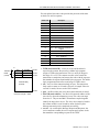
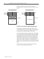
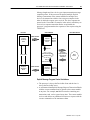
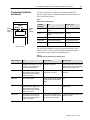
Installation Instructions
DeviceNet Scanner
Module
(Catalog Number 1747-SDN/B)
Contents
Module Features
For More Information...
Use this document as a guide when installing the 1747-SDN/B
scanner module.
To
prevent Electrostatic Discharge
understand compliance to European Union Directives
identify related publications
identify scanner module features
prepare for module installation
install the scanner module into the chassis
connect the scanner module to the DeviceNetTM drop line
apply chassis power
understand the data organization of the scanner module
program the scanner module using the M0 and M1 Files
upload input data from the scanner module
download output data from the scanner module
use the explicit message program control
troubleshoot the module and network
See page
3
3
4
4
6
7
8
9
9
11
14
18
20
27
For this reference information
Specifications
See page
30
The 1747-SDN/B has the following features. You activate these
features using DeviceNet Manager Software. For more information,
refer to your DeviceNet Manager Software User Manual (publication
number 1787-6.5.3) and your 1747-SDN Scanner Configuration
Manual (publication number 1747-6.5.2).
Slave Mode
The slave mode feature allows processor-to-processor
communication. Slave mode also allows the scanner to perform as a
slave device to another master on the network.
Like any other slave, when the scanner module is in slave mode, it
exchanges data with only one master. You control what information
is exchanged through scan list configuration and associated mapping
functions of DeviceNet Manager software.
Publication 1747-5.8 – July 1997
2
1747-SDN DeviceNet Scanner Module Installation Instructions
The slave mode function has the following variations:
The scanner is in:
When:
Null Mode
it contains an empty or disabled scan list (out-ofbox default)
Master Mode
it serves as a master to one or more slaves but is
not simultaneously serving as a slave to another
master
Slave Mode
it serves as a slave to another master
Dual Mode
it serves as both a master to one or more slaves
and as a slave to another master simultaneously
Change of State
The change of state function notifies the scanner module to perform
a scan:
• whenever a network data change occurs, or
• at a user-configurable heartbeat rate
Because data is only sent on an as-needed basis, change of state
increases system performance by reducing network traffic.
Cyclic I/O
The cyclic I/O feature allows you to set the scanner module to
perform a scan at a specific send rate.
Because data is only sent at a periodic rate, cyclic I/O increases
system performance by reducing network traffic.
Other New Information
Along with these new features are areas in this document that are
different from the previous edition. These areas are marked with
change bars (as shown to the right of this paragraph) to indicate the
addition of new or revised information.
Publication 1747-5.8 – July 1997
1747-SDN DeviceNet Scanner Module Installation Instructions
Prevent Electrostatic
Discharge
3
The scanner module is sensitive to electrostatic discharge.
!
ATTENTION: Electrostatic discharge can damage
integrated circuits or semiconductors if you touch
backplane connector pins. Follow these guidelines
when you handle the module:
• Touch a grounded object to discharge static potential
• Wear an approved wrist-strap grounding device
• Do not touch the backplane connector or
connector pins
• Do not touch circuit components inside the module
• If available, use a static-safe work station
• When not in use, keep the module in its
static-shield bag
Understand Compliance to
European Union Directives
If this product has the CE mark it is approved for installation within
the European Union and EEA regions. It has been designed and
tested to meet the following directives.
EMC Directive
This product is tested to meet Council Directive 89/336/EEC
Electromagnetic Compatibility (EMC) and the following standards,
in whole or in part, documented in a technical construction file:
• EN 50081-2EMC – Generic Emission Standard,
Part 2 – Industrial Environment
• EN 50082-2EMC – Generic Immunity Standard,
Part 2 – Industrial Environment
This product is intended for use in an industrial environment.
Low Voltage Directive
This product is tested to meet Council Directive 73/23/EEC
Low Voltage, by applying the safety requirements of EN 61131–2
Programmable Controllers, Part 2 – Equipment Requirements
and Tests.
For specific information required by EN 61131-2, see the appropriate
sections in this publication, as well as these Allen-Bradley
publications:
Publication
Industrial Automation Wiring and Grounding Guidelines
For Noise Immunity
Guidelines for Handling Lithium Batteries
Automation Systems Catalog
Publication number
1770-4.1
AG-5.4
B111
Publication 1747-5.8 – July 1997
4
1747-SDN DeviceNet Scanner Module Installation Instructions
Identify Related
Publications
For software configuration information, refer to your
DeviceNetManagerTM Software User Manual (publication number
1787-6.5.3) and your 1747-SDN Scanner Configuration Manual
(publication number 1747-6.5.2).
This icon is used when a
related publication is
referenced.
Identify Module Features
For planning and installation information, refer to the DeviceNet
Cable System Planning and Installation Manual (publication number
1485-6.7.1). If you need a copy of this manual, fax the enclosed User
Manual Request Card to 1-800-576-6340. If you are outside the U.S.,
fax the card to 1-330-723-4036.
Use this illustration to identify the features of the 1747-SDN/B
scanner module.
DeviceNet
Module Status Indicator
indicates module status
Node Address and Status Display
displays numeric codes and
indicates scanner node address
or error
STATUS
MODULE NET
Network Status Indicator
indicates status of the DeviceNet
channel communication link
ADDRESS/ERROR
Access door
Wiring Color
Codes
10-pin Linear Plug
inserted into
DeviceNet port
Front of Module
Publication 1747-5.8 – July 1997
20472–M
1747-SDN DeviceNet Scanner Module Installation Instructions
Series A Module Features
The Series A version of this module (1747-SDN) contains the
following features:
• DH-485 port
• different wiring label
• five-pin linear plug
DeviceNet
STATUS
MODULE NET
ADDRESS/ERROR
DH485 port
Five-pin linear
plug inserted
into DeviceNet
port
Wiring Label
Color Codes
Front of Module
20472–M
Publication 1747-5.8 – July 1997
5
6
1747-SDN DeviceNet Scanner Module Installation Instructions
Prepare for Module
Installation
Before you install your module you need the following items:
PC
User
Manual
WINDOWS
Personal Computer
with Microsoft
WindowsTM 3.1 or
later Operating
System
DeviceNet Manager
for Windows Software
Cat. No. 1787-MGR
DeviceNet Manager for
Windows Software
User Manual
Pub. No. 1787-6.5.3
Configuration
Manual
1747-SDN Scanner
Configuration Manual
Pub. No. 1747-6.5.2
1770-KFD RS-232 DeviceNet Adapter or 1784-PCD DeviceNet PC Card
SLC 1746 chassis with SLC
5/02, 5/03 or 5/04 processor
Before you install your module you must know how to:
• program and operate an Allen-Bradley SLC 500TM programmable
controller
• install and configure the devices on your DeviceNetTM network
Make Sure That Your Processor and Adapters are Compatible
You can use the 1747-SDN Scanner Module in a local I/O chassis
with only the SLC 500 processor running in the leftmost slot.
Important: The 1747-SDN Scanner Module fits in any slot of the
chassis except for the leftmost slot, which is reserved for
the SLC 500 processor.
Publication 1747-5.8 – July 1997
1747-SDN DeviceNet Scanner Module Installation Instructions
Install the Module Into the
Chassis
7
To install your module into the chassis:
1. Turn off the chassis power supply.
!
ATTENTION: Do not install the 1747-SDN Scanner
Module with the chassis power supply on. Installing
the module with the chassis power supply on may
damage the module.
2. Select a slot for the module in the chassis. You may use any slot
except the leftmost slot, which is reserved for the SLC 500
processor.
20442-M
3. Insert the module into the slot you have selected.
4. Apply firm, even pressure to seat the module in the I/O chassis
backplane connectors.
Publication 1747-5.8 – July 1997
8
1747-SDN DeviceNet Scanner Module Installation Instructions
Connect the Module to the
DeviceNet Drop Line
To connect your module to the DeviceNet drop line:
1. Turn off the network power supply.
ATTENTION: Do not wire the 1747-SDN Scanner
Module with the network power supply on. Wiring the
module with the network power supply on may short
your network or disrupt communication.
!
2. Connect the DeviceNet drop line to the ten-pin linear plug, by
matching the wire insulation colors to the colors shown on the
label:
Module label shows
wiring color scheme:
RED
Ten-pin
Linear
Plug
WHITE
BARE
DeviceNet
Drop Line
Red
White
Bare
BLUE
Blue
BLACK
D
D
D
D
D
20473–M
Front of Module
Black
20474-M
3. Locate the DeviceNet Port connector on the front of the module.
4. Insert the ten-pin linear plug into the DeviceNet Port connector.
Ten-pin
Linear
Plug
DeviceNet Port
Connector
20441–M
DeviceNet Drop Line
You have installed and wired your module. To operate the module
you must apply power and then configure and program the SLC
processor to communicate with it. We describe how to do this in the
next three sections.
Publication 1747-5.8 – July 1997
1747-SDN DeviceNet Scanner Module Installation Instructions
Apply Chassis Power
DeviceNet
STATUS
MODULE NET
Module
numeric
indicators
9
When you apply chassis power, the module numeric indicators cycle
through the following displays:
1. Seven-segment lamp test (88)
2. Firmware major revision (01 through 7F hexadecimal)
3. Firmware minor revision (01 through FF hexadecimal)
ADDRESS/ERROR
4. Baud rate (indicates 00 for the default of 125, 01 for 250 or
02 for 500 Kbits/s)
5. Node address (00 to 63 with 63 as the default)
Top part of module
Use the DeviceNetManager software to change the baud rate and
node address.
Refer to the Numeric Code Display Summary table on page 28 for a
complete listing of numeric displays.
Understand the Data
Organization of the
Module
The module has four data areas to transfer data, status and command
information between the module and the processor:
•
•
•
•
SLC input image table
SLC output image table
SLC M1 file
SLC M0 file
Input and Output Image Tables
The following table describes the mapping of the 1747-SDN input
and output image tables and the M1 and M0 files.
Words
SLC Input Image
Words
SLC Output Image
0
Status
0
Command
1–31
DeviceNet Input Data (31 words)
1–31
DeviceNet Output Data (31
words)
Words
SLC M1 File
Words
SLC M0 File
0–149
DeviceNet Input Data (150 words)
0–149
DeviceNet Output Data
(150 words)
150–223
Reserved
(74 words)
224–255
Explicit Message Program
Control (32 words)
150–209
Reserved (60 words)
210
Node Address/Status Indicator
(1 word)
211
Scan Counter (1 word)
212–215
Device Idle Table (4 words)
216–219
Device Failure Table (4 words)
220–223
Auto Verify Failure Table
(4 words)
224–255
Explicit Message Program Control
(32 words)
Publication 1747-5.8 – July 1997
10
1747-SDN DeviceNet Scanner Module Installation Instructions
SLC Memory Configuration ID Code
For More Information...
The ID code for the 1747-SDN scanner module is 13606. Use this
code to configure the memory of your SLC 5/02, 5/03 or 5/04
processor. Refer to the documentation supplied with your Advanced
Programming Software User Manual for additional information on
module ID codes and their use.
Use Advanced Programming Software to Configure M0-M1 Files
Use Advanced Programming Software (APS) to configure the M0
and M1 files for the processor. After you have assigned the module
to a slot, the following functions appear at the bottom of the APS
screen (the procedure is the same as assigning other modules but
you must specify the ID code (13606) of the scanner module):
MODIFY
RACKS
MODIFY
SLOT
DELETE
SLOT
UNDEL
SLOT
EXIT
SPIO
CONFIG
F4
F5
F6
F7
F8
F9
Complete the following steps to configure the M0 and M1 files:
1. Press [F9], SPIO CONFIG. The following functions
appear:
ISR
MODIFY
ADVNCD
G FILE
NUMBER
G FILE
SETUP
SIZE
F1
F3
F5
F7
2. Press [F5], ADVNCD SETUP. The following functions appear:
INPUT
SIZE
OUTPUT
SIZE
SCANNED
INPUT
SCANNED
OUTPUT
M0 FILE
SIZE
M1 FILE
SIZE
F1
F2
F3
F4
F5
F6
3. Press [F5], then enter 256 (the number of M1 file words
required).
4. Press [F6], then enter 256 (the number of M0 file words
required).
For More Information...
Publication 1747-5.8 – July 1997
For more information on how to configure your module for
DeviceNet operation and how to map data from DeviceNet nodes to
M1, M0, input and output image files, refer to your DeviceNet
Manager for Windows Software User Manual (publication number
1787-6.5.3) and your 1747-SDN Scanner Configuration Manual
(publication number 1747-6.5.2).
1747-SDN DeviceNet Scanner Module Installation Instructions
Program the Module Using
the SLC M0 and M1 Files
11
The M0 and M1 files are data files that reside in the module. There is
no image for these files in the processor memory. The M0 file is a
module output file and the M1 file is a module input file. Both M0
and M1 files are read/write files.
M0 and M1 files can be addressed in your ladder program and they
can also be acted upon by the module, independent of the processor
scan.
Important: During the processor scan, M0 and M1 data can be
changed by the processor according to ladder diagram instructions
addressing the M0 and M1 files. During the same scan, the module
can change M0 and M1 data, independent of the rung logic applied
during the scan.
Address the M0-M1 Files
The addressing format for M0 and M1 files is as follows:
Mf:S.w/b
Where
M = module
f = file (0 or 1)
S = slot (1–30)
w = word (0–maximum supplied by the module)
b = bit (0–15)
When You Cannot Use M0-M1 Data File Addresses
You can use M0 and M1 data file addresses in all instructions except
the OSR instruction and the instruction parameters below.
Instruction
Parameter (characterized by file indicator #)
BSL
BSR
File (bit array)
SQO
SQC
SQL
File (sequencer file)
LFL
LFU
LIFO (stack)
FFL
FFU
FIFO (stack)
Monitor Bit Instructions with M0 or M1 Addresses
When you monitor a ladder program in the Run or Test mode, the
following bit instructions, addressed to an M0 or M1 file, are
indicated as false regardless of their actual true/false logical state.
Mf:S.w
] [
b
Mf:S.w
]/[
b
Mf:S.w
( )
b
Mf:S.w
(L)
b
Mf:S.w
(U)
b
XIC
XIO
OTE
OTL
OTU
Publication 1747-5.8 – July 1997
12
1747-SDN DeviceNet Scanner Module Installation Instructions
To show the state of the M0 or M1 addressed bit, transfer the state to
an internal processor bit. This is illustrated below, where an internal
processor bit is used to indicate the true/false state of a rung.
B3
] [
0
B3
] [
1
EQU
EQUAL
Source A
N7:12
Source B
N7:3
M0:3.0
( )
1
This rung does not show its true rung state because the EQU instruction is always
shown as true and the M0 instruction is always shown as false.
B3
] [
0
B3
] [
1
EQU
EQUAL
Source A
N7:12
Source B
N7:3
B3
( )
2
M0:3.0
( )
1
OTE instruction B3/2 has been added to the rung. This instruction shows the true or
false state of the rung.
Transfer Data Between Processor Files and M0 or M1 Files
The processor does not contain an image of the M0 or M1 file so you
must edit and monitor M0 and M1 file data via instructions in your
ladder program. For example, you can copy a block of data from a
processor data file to an M0 or M1 data file or vice versa using the
COP (copy) instruction in your ladder program.
The COP instructions below copy data from a processor bit file and
integer file to an M0 file.
S:1
] [
15
First scan bit. It makes this rung
true only for the first scan after
entering the Run mode.
Publication 1747-5.8 – July 1997
COP
COPY FILE
Source
Dest
Length
#B3:0
M0:1.0
16
COP
COPY FILE
Source
Dest
Length
#N7:0
#M0:1.16
27
1747-SDN DeviceNet Scanner Module Installation Instructions
13
The COP instruction below copies six words of data from an M1
data file in a module positioned in slot four to an integer file (N1:0).
This technique is used to monitor the contents of an M0 or M1 data
file indirectly, in a processor data file. An update of these six words
is made for each SLC program scan.
COP
COPY FILE
Source
Dest
Length
#M1:4.3
#N10:0
6
Reduce Scan Time
Tip
To reduce processor scan time, use discretion when you use
instructions addressing the M0 or M1 files. For example, XIC
instruction M1:2.1/1 is used in rungs 1 and 2 below, adding
approximately 2 ms to the scan time if you are using a 5/02, Series B
processor.
1
M1:2.1
] [
1
2
B3
] [
12
B3
( )
10
M1:2.1
] [
1
B3
( )
14
XIC instructions in rungs 1 and 2 are addressed to the M1 data file. Each of
these instructions adds approximately 1 ms to the scan time (5/02, Series B
processor).
In the equivalent rungs below, XIC instruction M1:2.1/1 is used only
in rung 1, reducing the scan time by approximately 1 ms.
1
M1:2.1
] [
1
2
B3
] [
12
B3
( )
10
B3
] [
10
B3
( )
14
These rungs provide equivalent operation to those of the previous diagram by
substituting XIC instruction B3/10 for XIC instruction M1:2.1/1 in rung 2. Scan
time is reduced by approximately 1 ms (5/02, Series B processor).
The first two ladder diagrams in the last section illustrate a technique
you use to capture and use M0 or M1 data as it exists at a specific
time. In the first diagram, bit M1:2.1/1 could change state between
rungs 1 and 2. This could interfere with the logic applied in rung 2.
The second diagram avoids the problem. If rung 1 is true, bit B3/10
captures this information and places it in rung 2.
Publication 1747-5.8 – July 1997
14
1747-SDN DeviceNet Scanner Module Installation Instructions
The following diagram illustrates another economizing technique.
The COP instruction addresses an M1 file, adding approximately
4.29 ms to the scan time if you are using a 5/02, Series B processor.
You can save scan time by making this rung true only periodically.
For example, you can use a clock bit S:4/8 (clock bits are discussed
in the programming manual). A rung such as this might be used
when you want to monitor the contents of the M1 file, but
monitoring need not be continuous.
S:4/8 causes the M1:4.3
file to update the N10:0
file every 2.56 seconds.
S:4
] [
8
B11
[OSR]
0
COP
COPY FILE
Source
Dest
Length
#M1:4.3
#N10:0
6
In this example, a COP instruction can be used to monitor the
contents of an M1 file. When the instruction goes true, the six words
of data in file #M1:4.3 is captured as it exists at that time and placed
in file #N10:0. All subsequent logic should address the data in
#N10:0. The data will be consistent and it shortens scan time by
eliminating reads to the module each time an M0 or M1 address is
encountered in the program.
Upload Input Data from the
Module to the SLC
Processor
The SLC 500 processor reads input data from the module using two
methods:
• input image table
• M1 file transfer
Input Image Table
The input image table is a 32-word table for the module slot that is
updated by the processor with each program scan. The first word
(word 0) is reserved for the module status register. The remaining 31
words can be used to transfer DeviceNet input data to the SLC input
image table. The addressing format is:
I:S.w/b
Where
Publication 1747-5.8 – July 1997
S = slot
w = element (0–31)
b = bit (0–15)
1747-SDN DeviceNet Scanner Module Installation Instructions
15
Module Status Register
The module status register is located at word 0 in the input image
area for the slot. Bits 0–5 echo back to the processor, the current
state of bits 0–5 of the module command register. The echoes verify
that the commands were executed. The module sets the remaining
bits when it detects a problem. The bits latch in the ON state until the
problem clears. Bits 6 and 8 indicate that you should read the device
failure table for more specific information about which devices
failed.
You can use bit 6 to keep the communication port in the idle mode
until the bit clears. When the bit clears, this indicates that all devices
in the scanner’s scan list are up and available. When the devices are
available, you can put the port in run mode. If a device failure is
detected, you can put the communication into the idle mode, so that
all output devices go to a safe state.
The SLC program can monitor the bits in the module status register
and set the appropriate bits of the module command register to
automatically control the operating mode of the module should a
device failure occur.
Publication 1747-5.8 – July 1997
16
1747-SDN DeviceNet Scanner Module Installation Instructions
Status Word I:s.0
Operating Mode Description
Bit
Operating Mode
0
1 = run mode, 0 = idle mode (echoed
from the module command register)
1
1 = fault network (echoed from the
module command register)
2
Reserved
3
Reserved
4
1 = disable network (echoed from the
module command register)
5
Reserved
6
1 = device failure (at least one device
failed)
7
8
9
Run
The scanner module maps output data from its scanner output table (M0) and disp to each device on the network. Inputs
p are received and mapped
pp into the
crete outputs
scanner input table (M1) and discrete inputs.
inputs Outputs on the network are under SLC
program control.
Placing the key switch on the SLC into the PROG position places the scanner into
IDLE MODE regardless of the state of the bits in the module command register. Placing the key switch into the REM or RUN positions causes the state of the bits in the
module command register to determine the scanner state.
Reserved
Idle
Idl
The scanner does not map output data to the devices, but keeps network connections
to devices open so device failures can be detected. Input data is returned from
devices and mapped into the scanner input table (M1) and the discrete inputs
devices,
inputs. Outputs on the network are not under program control and will be in their configured ‘idle
state.’ The scanner must be put into this mode to perform offline configuration of the
scanner database tables.
Fault Network
The scanner has stopped communicating with devices on the network. No outputs
control. If scanor inputs
p are mapped.
pp Outputs
p on the network are not under pprogram
g
mode devices will go to their fault state.
state
ner was in run mode,
1 = autoverify failure (at least one device
has failed auto verify)
Disable Network
The DeviceNet channel is disabled for communication.
communication No communication may occur
over this channel. Outputs on the network are not under program control. If scanner
Reserved
was in run mode, devices will go to their fault state.
10
1 = communication failure
11
Reserved
12
1 = duplicate node address failure
13
Reserved
14
Reserved
15
1 = Explicit Message Program Control
Response available in M1 file.
0 = Empty
Device Failure
O or more off the
One
th devices
d i in
i the
th scanner’s
’ scan list
li t has
h failed
f il d to
t communicate
i t with
ith
the scanner.
Autoverify Failure
One or more of the devices in the scanner’s
scanner s scan list is returning an incorrect number
of bytes of data in response to a strobe/poll, according to the information stored in the
scanner’ss scan list.
scanner
Communications Failure
port
There is no communication on the port.
Duplicate Node Address Failure
There is another node with the same address as the scanner on the network.
SLC M1 File
The SLC M1 file is a 256 word file that can be used to transfer a
large quantity of information to the module with a single SLC
instruction. Transferring data using this file takes more time than
using the input image table.
Publication 1747-5.8 – July 1997
1747-SDN DeviceNet Scanner Module Installation Instructions
17
The first 150 words are used for data transfer from the module. The
remaining 106 words are reserved for:
• node status
• scan counter
• device idle table
• device failure table
• auto verify table
• explicit message program control
For a detailed description of the mapping of input and output image
tables, refer to page 9.
Node Address/Status Indicator
Word 210 is used for node address and scanner diagnostic
information displayed in numeric codes. The descriptions of these
codes are listed on page 28.
Scan Counter
Word 211 is used for the module scan counter. The module
increments this counter whenever a scan of the DeviceNet devices is
completed. The counter rolls over when it reaches a maximum value
of 65535. It is located at M1:S.211.
Device Idle Table
Words 212 through 215 in the M1 file are used for the device idle
table. This table indicates that there are devices on the network in
idle mode. The module tracks devices in idle mode by assigning one
of the 64 bits in the table to each device on the network. The bits are
assigned in consecutive order to consecutive device addresses
starting at mode 0 at M1.S.212/0.
Device Failure Table
Words 216 through 219 in the M1 file are used for the device failure
table. This table indicates communication failures of devices on the
network. The module tracks device failures by assigning one of the
64 bits in the table to each device on the network. The bits are
assigned in consecutive order to consecutive device addresses
starting at mode 0 at M1.S.216/0.
Publication 1747-5.8 – July 1997
18
1747-SDN DeviceNet Scanner Module Installation Instructions
Auto Verify Failure Table
Words 220 through 223 in the M1 file are used for the auto verify
failure table. The auto verify failure table is used to verify that data
size received from the device matches the setting in the module input
data map. The module tracks auto verify failures by assigning one of
the 64 bits in the table to each device on the network. The bits are
assigned in consecutive order to consecutive device addresses
starting with node 0 at M1:S.220/0. If the bit is set, the
corresponding node has failed to verify.
Explicit Message Program Control
Words 224 through 255 are used for Explicit Message Program
Control. Use this feature to configure device parameters on your
DeviceNet network via the M0 and M1 files in the SLC processor
that is controlling these devices. This feature is described in detail on
page 20.
Download Output Data to
the Module
The SLC 500 processor writes output data to the module using two
methods:
• output image table
• M0 file transfer
Output Image Table
The output image table is a 32-word table for the module slot that is
updated from the processor with each program scan. The first word
(word 0) of this table is reserved for the module command register.
The remaining 31 words can be used to transfer data from the SLC
output table to the DeviceNet nodes.
Module Command Register
The module command register is located at word 0 in the output
image area for the slot. To execute a command, set the appropriate
bits in the module command word using SLC ladder instructions.
The following table describes the functionality of the command
register bits.
Publication 1747-5.8 – July 1997
1747-SDN DeviceNet Scanner Module Installation Instructions
19
Command Word 0:S.0
Bit
Operating Mode
0
1 = run mode, 0 = idle mode
1
1 = fault network
2
Reserved1
3
Reserved1
4
1 = disable network
5
Reserved1
6
1 = halt scanner
7
1 = reboot
8–15
Reserved1
Operating Mode Description
Run
The scanner module maps output data from its scanner output table (M0) and discrete
outputs to each device on the network. Inputs are received and mapped into the scanner
input table (M1) and discrete inputs. Outputs on the network are under SLC program
control.
t l
Idle
The scanner does not map output data to the devices, but keeps network connections
to devices open so device failures can be detected. Input data is returned from devices,
and mapped into the scanner input table (M1) and the discrete inputs. Outputs on the
network are not under program control and will be in their configured ‘idle state.’ The
scanner is put into this mode to perform online configuration of the scanner database
tables.
Placing the key switch on the SLC into the PROG position places the scanner into IDLE
MODE regardless of the state of the bits in the module command register. Placing the
key switch into the REM or RUN positions causes the state of the bits in the module command register to determine the scanner state.
Fault Network
The scanner stops communicating with devices on the network. No outputs or inputs are
mapped.
apped Outputs on
o the
t e network
et o are
a e not
ot under
u de program
p og a control.
co t o If scanner
sca e was
as in run
u
mode devices will go to their fault state.
state
mode,
Disable Network
The DeviceNet channel is disabled for communication. No communication may occur
over this channel. Outputs on the network are not under program control. If scanner was
in run mode, devices will go to their fault state.
Halt Scanner
p
All scanner operations
stopp when this command is issued. No communications occur
over either DeviceNet port.
port No block transfer or discrete I/O mapping occurs.
occurs Outputs
on the network are not under program control. If scanner was in run mode, devices will
go to their fault state. and will be in their configured ‘safe state.’
Reboot
This command causes the scanner to reset as though power had been cycled. When
this command is issued, all scanner communication stops for the duration of the scanner’s initialization sequence. Outputs on the network are no longer under program control. If scanner was in run mode, devices will go to their fault state.
1 All reserve bits must be set to zero or improper operation may result.
SLC M0 File
The SLC M0 file is a 256 word file that can be used to transfer a
large quantity of information to the module with a single SLC
instruction. Transferring data using this file can take several scans
and more time than using the output image table. The first 150 words
are used for sending data to DeviceNet nodes. The next 74 words are
reserved for future use and the last 32 words are used for explicit
message program control.
For a detailed description of the mapping of input and output image
tables, refer to page 9.
Publication 1747-5.8 – July 1997
20
1747-SDN DeviceNet Scanner Module Installation Instructions
Explicit Message Program
Control
Use the Explicit Message Program Control feature to configure
device parameters on your DeviceNet network via the M0 and M1
files in the SLC processor that is controlling these devices.
You can use Explicit Message Program Control only with devices
that are slaves of your 1747-SDN Scanner Module. These slave
devices must be mapped in the scanner module’s scan list.
Use the Explicit Message Program Control feature to:
• transmit configuration data from your scanner module to its slave
devices on your DeviceNet network
• receive status and diagnostics from these devices on your
DeviceNet network
• make runtime adjustments to device parameters according to
changing conditions detected by your processor
How the Explicit Message Program Control Feature Works
MC0 file transfer (including words 224-255)
(sent from processor to scanner module)
4
MC1file transfer (including words 224-255)
(sent from scanner module to processor)
Request – An explicit message sent by a client
to a server requesting the server to perform
a function.
Response – An explicit message sent by a
server to a client in response to the client’s
request. For every request issued, there is a
response.
5
MC1 file transfer
is completed. TXID’s
are deleted and can be
reused.
DeviceNet trunk line
Explicit Message – A message used to transmit
commands, data, requests for data or
responses. The message is sent from a client on
the DeviceNet network to a server on that
network.
Master’s Explicit
Request
DeviceNet
drop line
Slave’s Explicit
Response
Publication 1747-5.8 – July 1997
1203-GK5
Communication
Adapter
1305 AC
drive
1747-SDN DeviceNet Scanner Module Installation Instructions
21
1. Format an M0 file transfer in the processor to send an Explicit
Message Request to the scanner module (download).
2. The scanner module transmits the Explicit Message Request to
the slave device over the DeviceNet network.
3. The slave device transmits the Explicit Message Response back
to the scanner and is queued into a file transfer buffer.
4. The processor uses an M1 file transfer to retrieve the Explicit
Message Response from the scanner’s buffer (upload).
5. Format an M0 file transfer with a Delete Response Command and
the current transaction ID read in step 4. The transaction IDs are
deleted and can be reused.
The scanner module requires a precisely-formatted M0 and M1 file
transfer size of 32 words including words 224-255. The scanner
module uses the file memory content as a client/server request.
How to Format the Explicit Message Transaction Block
Up to ten 32-word transaction blocks may be queued within the
scanner module for Explicit Message Program Control. The
transaction blocks accommodate both the download of Explicit
Message Requests and the upload of Explicit Message Responses.
The scanner module can accommodate one request or response for
each transaction block. You must format each transaction block as
shown in the following figure:
15
Transaction
Header
(3 words)
0
TXID
cmd/status
word 224
port
size
word 225
MAC ID
word 226
service
Transaction Body
(29 words)
word 255
One word = two bytes = 16 bits
The transaction block is divided into two parts:
• transaction header – contains information that identifies the
transaction to the scanner and processor
Publication 1747-5.8 – July 1997
22
1747-SDN DeviceNet Scanner Module Installation Instructions
• transaction body – in a request, this contains the DeviceNet
Class, Instance, Attribute and Service Data portion of the
transaction. In a response, this contains only the response
message.
Each of the data attributes in the transaction header are one byte in
length:
• command/status – for each download, you assign a command
code to instruct the scanner how to administer the request:
Publication 1747-5.8 – July 1997
Command Code
Description
0
Ignore transaction block (block empty)
1
Execute this transaction block
2
Get status of transaction TXID
3
Reset all client/server transactions
4
Delete transaction from response queue
5–255
Reserved
1747-SDN DeviceNet Scanner Module Installation Instructions
23
For each upload, the status code provides the processor with status
on the device and its response:
15
Transaction
Header
(3 words)
TXID
cmd/status
word 224
port
size
word 225
MAC ID
word 226
Transaction Body
(29 words)
•
word 255
One word = two bytes = 16 bits
Description
0
Ignore transaction block (block empty)
1
Transaction completed successfully
2
Transaction in progress (not ready)
3
Error – slave not in scan list
4
Error – slave offline
5
Error – DeviceNet port disabled/offline
6
Error – transaction TXID unknown
7
Error – slave not responding to request
8
Error – Invalid command code
9
Error – Scanner out of buffers
10
Error – Other Client/server transaction in
progress
11
Error – could not connect to slave device
12
Error – response data too large for block
13
Error – invalid port
14
Error – invalid size specified
15
Error – connection busy
16–255
Reserved
• TXID (transaction ID) – when you create and download a
0
service
Status Code
•
•
•
request to the scanner, the processor’s ladder logic program
assigns a TXID to the transaction. This is a one-byte integer in
the range of 1 to 255. The scanner uses this value to track the
transaction to completion, and returns the value with the response
that matches the request downloaded by the processor. The ladder
logic program monitors rollover and usage of TXID values.
size – the size of the transaction body in bytes. The transaction
body can be as many as 29 words (58 bytes) in length. If the size
exceeds 29 words, an error code will be returned.
port – the DeviceNet port (zero) where the transaction is routed.
MAC ID (node address) – the DeviceNet network address of the
slave device where the transaction is sent. This value can range
from 0 to 63. The port and MAC ID attributes coupled together
identify the target slave device. The slave device must be listed in
the scanner module’s scan list and be online for the Explicit
Message transaction to be completed successfully.
service – for each Explicit Message Request and Response, the
service attribute contains the service request and response codes
that match the corresponding request for the TXID.
Publication 1747-5.8 – July 1997
24
1747-SDN DeviceNet Scanner Module Installation Instructions
The following figure describes the format and mapping of
transaction blocks for request and response messages in the scanner
module:
Format of 32-word M1 Transfer File
for Explicit Message Response
15
0
Format of 32-word M0 Transfer File
for Explicit Message Request
15
0
Transaction
Header
(3 words)
TXID
command
port
size
service
word 224
MAC ID
Transaction
Header
(3 words)
TXID
status
port
size
service
word 224
MAC ID
Class
Instance
Attribute (optional)
Transaction #1
Transaction #1
Service Response Data
Service Data
word 225
word 225
How the Processor and Scanner Module Manage Messages
File transfer operations between the processor and the scanner
always originate in the processor. The scanner module can only wait
for the processor to download a transaction block to the module or
request an upload of a transaction block from the module.
Once an Explicit Message Request transaction block is downloaded
to the scanner module, a ladder logic program in the processor polls
the scanner module for the transaction block containing the Explicit
Message Response for that request. This is done by the processor
with an M1 file transfer on the scanner module. Depending on the
network load, the scanner could take a few seconds to complete the
request. When a response is loaded, bit 15 of the module status
register is set to 1. The program may have to poll the scanner module
a number of times before the scanner returns a Response Transaction
Block.
The scanner module recognizes I/O data and control as higher
priorities over explicit messaging on DeviceNet.
Publication 1747-5.8 – July 1997
1747-SDN DeviceNet Scanner Module Installation Instructions
25
Message lengths and slave device types impact transaction message
completion times. If the processor has queued multiple Explicit
Message Transactions to the scanner module for multiple slave
devices, the transactions with the slaves may not complete in the
order in which the requests were received. The slave responses are
queued to the 32 word M1 file transfer in the order in which they are
received. As response transaction blocks are uploaded, the
processor’s program matches the responses to the requests using the
TXID field.
Processor
Scanner Module
DeviceNet Network
M0 file transfer
Request
Transaction
Block
Request
Transaction
Blocks
Scanner
Request
Queue
Execute
DeviceNet
Explicit Message
Requests and
Responses
Process Requests
and Responses
Ladder Scans
Slave
Device
Done or
Error-detected
Response
Transaction
Block
M1 file transfer
Response
Transaction
Blocks
Scanner
Response
Queue
Explicit Message Program Control Limitations
• The processor is always the DeviceNet client and the slave is
always the DeviceNet server.
• A maximum of ten Explicit Message Request Transaction Blocks
with the execute command can be queued to the scanner module
at any time. For example, ten M0 file transfers containing one
transactions each, can be queued at any time. The scanner module
receives and deletes any additional client/server requests with the
execute command over the maximum of ten.
Publication 1747-5.8 – July 1997
26
1747-SDN DeviceNet Scanner Module Installation Instructions
As transactions are removed from the queue and response transaction
blocks are returned to the processor, additional transaction blocks
can be issued in their place, as long as the total does not exceed ten.
• The scanner module supports one transaction block per upload
and download.
• Request Transaction Blocks can only be queued for slave devices
of the scanner module and must appear in the scanner module’s
scan list.
• If a slave device is not communicating at the time the scanner
module processes its Request Transaction Block, the scanner
module will return an error status for that transaction.
• At a minimum, the scanner module supports the following
DeviceNet services in Request Transaction Blocks:
Service Name:
Service Code: Example:
Get_Attribute_Single
0E hex
Upload a single parameter value
from a device
Set_Attribute_Single
10 hex
Download a single parameter value
to a device
Get_Attribute_All
01 hex
Upload all parameter values from a
device
Set_Attribute_All
02 hex
Download all parameter values to a
device
• All transaction blocks are processed, therefore, an unused
transaction block must be left blank.
• Client/Server commands and requests with transaction IDs that
are in use are ignored by the scanner module.
• If a slave device returns a DeviceNet error in response to the
request downloaded from the processor, the scanner recognizes
the error as a successful transaction (status code =1).
A failure to respond to the request within the number of retries or
timeout period specified for the Explicit Message Connection is
recognized by the scanner module as an error. The error code is
returned in the status attribute of the transaction header.
Publication 1747-5.8 – July 1997
1747-SDN DeviceNet Scanner Module Installation Instructions
Troubleshoot the Module
and Network
27
The bicolor (green/red) module status indicator (MODULE)
displays module status. It indicates whether the module has power
and is functioning properly.
Table 1
Module Status Troubleshooting
DeviceNet
STATUS
MODULE NET
Module
Status
Indicator
Network
Status
Indicator
If MODULE
indicator is:
Then:
Take this action:
Off
There is no power applied to the
module.
Apply power.
Green
The module is operating in normal
condition.
Do nothing.
Flashing Green
The module is not configured.
Configure the module.
Flashing Red
There is invalid configuration.
Check configuration setup.
Red
The module has an unrecoverable
fault.
Replace the module.
ADDRESS/ERROR
Top part of module
The DeviceNet channel has a bicolor (green/red) network status
indicator (NET). Table 2 provides troubleshooting information
about the DeviceNet channel communication link.
Table 2
DeviceNet Channel Communications Troubleshooting
If NET indicator is:
Then :
Which Indicates:
Take this action:
Off
The device has no power or the channel
is disabled for communication due to bus
off condition, loss of network power, or
has been intentionally disabled.
The channel is disabled for
DeviceNet communication.
Power-up the module, provide network
power to channel, and be sure channel is
enabled in both the module configuration
table and module command word.
Flashing Green
The two-digit numeric display for the
channel indicates an error code that
provides more information about the
condition of the channel.
The channel is enabled but no
communication is occurring.
Configure scan list table for channel to
add devices.
Solid Green
There’s normal operation.
All slave devices in the scan list table
are communicating normally with the
module.
None.
Solid Red
The communications channel has failed.
The two digit numeric display for the
channel displays an error code that
provides more information about the
condition of the channel.
The module may be defective.
Reset module. If failures continue,
replace module.
Flashing Red
The two-digit numeric display for the
channel displays an error code that
provides more information about the
condition of the channel.
At least one of the slave devices in
Examine the failed device and the scan
the module’s scan list table has failed list table for accuracy.
to communicate with the module.
Publication 1747-5.8 – July 1997
28
1747-SDN DeviceNet Scanner Module Installation Instructions
DeviceNet
STATUS
MODULE NET
Node Address
and Status
Display
Your module uses numeric displays to indicate diagnostic
information about the status of your module. The display flashes at 1
second intervals. Table 3 summarizes the meanings of the numeric
codes.
Table 3
Numeric Code Display Summary
ADDRESS/ERROR
Numeric Code:
Description:
Take this action:
Network Address
Displays
0 - 63
Normal operation. The numeric display matches
the scanner’s node address on the DeviceNet
network.
None.
70
Module failed Duplicate Node Address check
Change the module channel address to another
available one. The node address you selected
is already in use on that channel.
71
Illegal data in scan list table (node number
alternately flashes).
Reconfigure the scan list table and remove any
illegal data.
72
Slave device stopped communicating (node
number alternately flashes).
Inspect the field devices and verify connections.
73
Device key parameters do not match scan list
table entry (node number alternately flashes).
Enter a matching scan list device ID. Make sure
that the device at the flashing node address
matches the desired key parameters (vendor,
product code, product type).
74
Data overrun on port detected.
Modify your configuration and check for invalid
data.
75
No scan list is active in the module.
Enter a scan list.
76
No direct network traffic for module detected.
None. The module hears other network
communication.
77
Data size returned does not match scan lists
entry (node number alternately flashes).
Reconfigure your module and change the
addressing.
78
Slave device in scan list table does not exist
(node number alternately flashes).
Add the device to the network, or delete the
scan list entry for that device.
79
Module has failed to transmit a message.
Make sure that your module is connected to a
valid network. Check for disconnected cables.
Verify baud rate.
80
Module is in IDLE mode.
None.
81
Module is in FAULT mode.
None.
82
Error detected in sequence of fragmented I/O
Check scan list table entry for slave device to
messages from device (node number alternately make sure that input and output data lengths are
flashes).
correct. Check slave device configuration.
83
Slave device is returning error responses when
module attempts to communicate with it (node
number alternately flashes).
Check accuracy of scan list table entry. Check
slave device configuration.
84
Module is initializing the DeviceNet channel.
None. This code clears itself once module
attempts to initialize all slave devices on the
channel.
85
Data size returned is bigger than expected.
Check accuracy of scan list table entry. Check
slave device configuration.
Top part of module
Publication 1747-5.8 – July 1997
1747-SDN DeviceNet Scanner Module Installation Instructions
Numeric Code:
Description:
29
Take this action:
86
Device is producing idle state data while the scanner is Check device configuration/slave node status.
in Run Mode.
87
Available for allocation. Scanner has not yet been
detected by allocated master, or slave mode is
enabled but scanner is not allocated to a master.
88
This is not an error. At power-up and reset, the module None.
displays all 14 segments of the node address and
status display LEDs.
90
User has disabled communication port
Reconfigure your module.
Check the disable bit in the Module Command
Register.
91
Bus-off condition detected on comm port. module is
detecting communication errors.
Check DeviceNet connections and physical
media integrity. Check system for failed slave
devices or other possible sources of network
interference.
92
No network power detected on comm port.
Provide network power. Make sure that module
drop cable is providing network power to module
comm port.
95
Application FLASH update in progress.
None. Do not disconnect the module while
application FLASH is in progress. You will lose
any existing data in the module’s memory.
97
module halted by user command.
None.
98
Unrecoverable firmware failure.
Service or replace your module.
99
Unrecoverable hardware failure.
Service or replace your module.
E9
Non-volatile configuration corrupt.
Cycle power to module.
Download configuration to module.
Monitor scanner to determine if error code clears
when master detects scanner.
If error remains, check scanner slave mode
configuration.
Publication 1747-5.8 – July 1997
30
1747-SDN DeviceNet Scanner Module Installation Instructions
Specifications
Module Location
Module Defaults
Backplane Current
DeviceNet Power
Requirements1
Isolation Voltage
Environmental Conditions:
Operational Temperature
Storage Temperature
Relative Humidity
Shock Unpackaged
Vibration Unpackaged
Immunity Radiated Fields
Agency Certification
(when product or packaging is
marked)
User Manual
SLC 5/02, 5/03 or 5/04 chassis
Node Address – 63
Baud Rate – 125 Kbits/s
500 mA @ 5Vdc
24Vdc @ 90mA each channel (maximum)
Optical Isolation between backplane and DeviceNet channel
1 Megohm resistor from DeviceNet channel to chassis
0-60oC (32-140oF)
-40 to 85oC (–40 to 185oF)
5-95% without condensation
30g operational
50g non-operational
5g from 10-150Hz
10V/m
27mHz-1000mHz
ÎÎ
Î
ÎÎ
Î
Class 1 Division 2, groups A, B, C, D 2
marked for all applicable directives
1747-6.5.2
1To remain compliant with UL/CSA certification, the DeviceNet power supply must meet NEC Class II requirements.
DeviceNet is a trademark of the Open DeviceNet Vendors Association.
SLC, SLC 500, SLC 5/02, SLC 5/03 and SLC 5/04 are trademarks of Allen-Bradley Company, Inc.
Windows is a trademark of Microsoft Corporation.
Allen-Bradley, a Rockwell Automation Business, has been helping its customers improve
productivity and quality for more than 90 years. We design, manufacture and support a broad
range of automation products worldwide. They include logic processors, power and motion
control devices, operator interfaces, sensors and a variety of software. Rockwell is one of the
world’s leading technology companies.
Worldwide representation.
Argentina • Australia • Austria • Bahrain • Belgium • Brazil • Bulgaria • Canada • Chile • China, PRC • Colombia • Costa Rica • Croatia • Cyprus • Czech Republic •
Denmark • Ecuador • Egypt • El Salvador • Finland • France • Germany • Greece • Guatemala • Honduras • Hong Kong • Hungary • Iceland • India • Indonesia •
Ireland • Israel • Italy • Jamaica • Japan • Jordan • Korea • Kuwait • Lebanon • Malaysia • Mexico • Netherlands • New Zealand • Norway • Pakistan • Peru •
Philippines • Poland • Portugal • Puerto Rico • Qatar • Romania • Russia–CIS • Saudi Arabia • Singapore • Slovakia • Slovenia • South Africa, Republic • Spain •
Sweden • Switzerland • Taiwan • Thailand • Turkey • United Arab Emirates • United Kingdom • United States • Uruguay • Venezuela • Yugoslavia
Allen-Bradley Headquarters, 1201 South Second Street, Milwaukee, WI 53204 USA, Tel: (1) 414 382-2000 Fax: (1) 414 382-4444
Publication 1747-5.8 – July 1997
Supersedes Publication 1747-5.8 – January 1997
Publication 1747-5.8 – July 1997
PN 955129-69
Copyright 1997 Allen-Bradley Company, Inc. Printed in USA