1
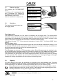
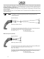
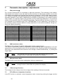
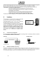
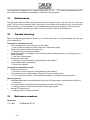
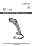
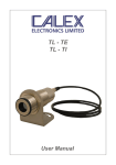
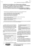
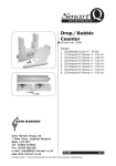
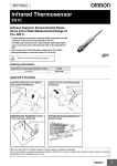
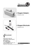
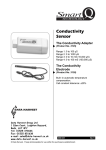
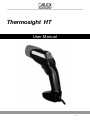
Thermosight HT Thermosight HT User Manual -1- Thermosight HT Content 1 General........................................................................................................................................3 1.1 Information to the user manual......................................................................................3 1.2 Limit of liability and warranty..........................................................................................3 1.3 Legend............................................................................................................................3 1.4 Terminology....................................................................................................................3 1.5 Copyright........................................................................................................................3 1.6 Disposal / decommissioning...........................................................................................4 2 Technical data............................................................................................................................4 3 Overview.....................................................................................................................................4 3.1 Instrument.......................................................................................................................4 3.2 Display............................................................................................................................5 3.3 Appropriate use..............................................................................................................5 3.4 Scope of delivery............................................................................................................5 4 Safety..........................................................................................................................................5 4.1 General...........................................................................................................................6 4.2 Laser targeting light........................................................................................................6 4.3 Ambient temperature......................................................................................................6 5 Commissioning..........................................................................................................................6 5.1 Battery insertion.............................................................................................................7 5.2 Switch on........................................................................................................................7 5.3 Sighting...........................................................................................................................7 5.4 Spot size.........................................................................................................................7 6 Display functions / Setting keys..............................................................................................9 7 Parameter description / adjustments....................................................................................10 7.1 EMI (emissivity ε).........................................................................................................10 7.2 MAX (maximum value).................................................................................................10 7.3 MIN (minimum value)...................................................................................................10 7.4 AVG (average function)................................................................................................10 7.5 DIF (difference temperature function)..........................................................................10 7.6 HI (hi alarm)..................................................................................................................11 7.7 CLR (clearing the stored measured values)................................................................11 7.8 STO# (determine the storage position)........................................................................11 7.9 RCL# (recall measured values)....................................................................................11 7.10 INT (time interval for storage of measured values)....................................................11 7.11 C / F (temperature display in °C or °F).......................................................................11 7.12 Time............................................................................................................................11 8 Interface....................................................................................................................................12 8.1 Connector pin assignment...........................................................................................12 8.2 Software PortaWin (accessory)....................................................................................12 9 Special displays of the pyrometer.........................................................................................13 10 Transport, packaging, storage.............................................................................................13 11 Maintenance ..........................................................................................................................14 12 Trouble shooting ..................................................................................................................14 13 Reference numbers...............................................................................................................14 -2- Thermosight HT 1 General 1.1 Information to the user manual Congratulations on choosing the high quality and highly efficient CALEX Pyrometer. Please read this manual carefully and step for step including all notes to security, operation and maintenance before using the pyrometer. For operation of the instrument this manual is an important source of information and work of reference. To avoid handling errors keep this manual in a location where you always have access to. If operating the instrument it is necessary to follow the generally safety instructions (see 4 Safety). Additionally to this manual the manuals of the of the used components are valid. All notes – especially safety notes – are to consider. 1.2 Limit of liability and warranty All general information and notes for handling, maintenance and cleaning of this instrument occurs to the best of our knowledge under consideration of our know-how. CALEX is not liable for any damages that arise from the use of any examples or processes mentioned in this manual or in case the content of this document should be incomplete or incorrect. CALEX reserves the right to revise this document and to make changes from time to time in the content hereof without obligation to notify any person or persons of such revisions or changes. All series THERMOSIGHT Instruments from CALEX have a warranty of two years from the invoice date. This warranty covers manufacturing defects and faults which arise during operation only if they are the result of defects caused by CALEX. This warranty is void if the instrument is disassembled, tampered with, altered or otherwise damaged, without prior written consent from CALEX. 1.3 Legend Note The note symbol indicates tips and useful information in this manual. All notes should be read with regard to an effective operation of the instrument. Security note laser beam Indicates to the danger of a built-in laser targeting light. 1.4 Terminology The used terminology corresponds to the VDI- / VDE-directives 3511, page 4. 1.5 Copyright All copyrights reserved. This document may not be copied or published, in part or completely, without the prior written permission of CALEX. Contraventions are liable to prosecution and compensa- -3- Thermosight HT tion. All rights reserved practicing industrial property rights. 1.6 Disposal / decommissioning Inoperable CALEX pyrometers have to be disposed corresponding to the local regulations of electro or electronic material. 2 Technical data Temperature range: Spectral range: Detector: Accuracy: Repeatability: Temperature coefficient: Exposure time t90: Emissivity: Temperature display: Temperature resolution: Temp. below 250°C: Temp exceeds 1800°C: Display illumination: Measuring unit: Measuring functions: Alarm functions: Data storage: Storage interval: Serial interface: Analog output: Power supply: Battery life: (without backlight) Charging connector: Ambient temperature: Storage temperature: Housing: Weight: Fixing thread: Protection class: CE-label: 3 Overview 3.1 Instrument -4- 250 … 1800°C 1.45 ... 1.8 µm InGaAs detector 0.75% of reading (TU = 23°C, EMI = 100%) 0.2% of reading 0.03% of reading in °C per °C deviation of ambient temperature of 23°C 20 ms (with dynamical adaptation at low signal levels) 10 ... 100%, adjustable in 1% steps 3 values / s large display: 4 digit, height 9 mm small display: 4 digit, height 4.5 mm on display: 0.1°C: 250 ... 999.9°C; 1°C: 1000 ... 1800°C 0.1°F: 482 ... 999.9°F, 1°F: 1000 ... 3272°F via interface: 0.1°C or 0,1°F on display: 7777 on display: 8888 automatically at dark ambient light conditions °C / °F, switchable Normal, MAX, MIN, AVG, DIF Hi-alarm (adjustable) 750 values; storage of: temperature value, date, time, parameter, emissivity, address, interval, temperature unit in °C or °F PRT; OFF; 0.02 s; 0.04 s; 0.1 s; 0.2 s; 0.5 s; 1 s; 2 s; 5 s; 10 s; 20 s; 50s RS232 interface with 57600 Baud 1 mV/°C or 1 mV/°F; resolution 1 degree 9 V battery (IEC 6LR61) or 9 V-NiMH rechargeable battery (e.g. Varta type 5622) 50 hours (without laser) with 9 V battery 15 hours (without laser) with 9 V rechargeable battery connector for battery charging unit 3 858 490 0 ... 60 °C -20 ... 70 °C ABS, UL class V0 340 g photo tripod thread 1/4“ - 20 UNC IP20 according to EU directives about electromagnetic immunity Thermosight HT Laser warning Protection cap Display Spot size table Keys Fixing lever for continuous measurement Connector for battery charger Switch Battery case Connector for RS232 interface and analog output Carrying loop Tripod thread 3.2 Display Display in °C or °F Sensor for automatic display illumination Battery low Laser targeting light active Parameter / Function Hold function Laser targeting light function changing values Temperature display Parameter value / Function value Choose parameter or function 3.3 Appropriate use The portable pyrometer THERMOSIGHT HT is a robust, digital and highly accurate infrared thermometer with built-in data logger (750 temperature values) for non-contact temperature measurement on metals, ceramics, graphite etc. with a temperature range of 250 … 1800°C. 3.4 Scope of delivery Instrument (incl. battery), carrying case, inspection sheet, user manual. 4 Safety This section offers an overview about all important safety aspects. Additionally in the several sections there are concrete safety aspects to avert danger. These as- -5- Thermosight HT pects are indicated with symbols. Labels and markings at the instrument have to be noticed and keep in a permanent readable condition. 4.1 General Each person working with the pyrometer must have read and understood the user manual before operation. Also this has to be done if the person already used similar instruments or was already trained by the manufacturer. The pyrometer has only to be used for the purpose described in the manual. It is recommended to use only accessories offered by the manufacturer. 4.2 Laser targeting light For easy alignment to the measuring object the pyrometers is equipped with a laser targeting light. This is a visible red light with a wavelength between 630 and 680 nm and a maximum power of 1 mW. The laser is classified as product of laser class 2. Caution: Do not look directly into the laser beam! Laser class 2 according to IEC 60825-1-3-4 Safety regulations: • Never look directly into the laser beam. The beam and spot can be watched safely from side. • Make sure that the beam will not be reflected into eyes of persons by mirrors or shiny surfaces. 4.3 Ambient temperature The pyrometer is designed for ambient temperatures of 0 … 60°C with non-condensing conditions. An operation out of these conditions can damage or malfunction to the pyrometer. 5 Commissioning -6- Thermosight HT 5.1 Battery insertion For operating the THERMOSIGHT HT a 9 V battery or 9 V rechargeable battery is necessary. For insertion of the battery remove the locking screw and the battery case cover. Now the instrument is ready to use. 5.2 Switch on Battery case Battery case cover Battery connector Locking screw for battery case cover Locking lever The instrument’s push button has two trigger points. Push button with 2 trigger points First trigger point: The instrument is switched on if the button is pushed to the first trigger point. The measurement starts after a short self test of approximately 1 second. After releasing the push button the last measured value will be displayed for 10 seconds (HOLD function) and the sign “HOLD” is shown on the display. After these 10 seconds the instrument is switched off automatically. The display indicates “7777” if the measured temperature is below 250°C, it indicates “8888” above 1800°C. Second trigger point: The second trigger point activates the data logger and stores the actual temperature reading. It can be adjusted if only the actual temperature value is stored or if a continuous storing should be done as long as the push button is hold on the second trigger point (setting of time interval see 8.10). The data logger can store up to 750 temperature values. Should the pyrometer be switched to single value data logging, the data logging is confirmed by a beep and in the display the used number of the stored value is indicated for a short time (e.g. for the first stored value STO# 01 is shown). The pushbutton can be locked in the second trigger point position with the locking lever by pushing the lever upwards. This activates the continuous measuring mode. Pressing the trigger once again releases the locking and switches off the continuous measuring mode. 5.3 Sighting For exact aiming to the object the pyrometer is equipped with a laser targeting light. The laser shows a red flashing circle at the position of the measuring spot on the object. The size of the circle varies depending on the distance and has approximately the size of the measuring spot. If the instrument is in operation the laser targeting light function can be activated or deactivated by pressing the laser key. If this function is activated the laser targeting light is automatically switched on as long as the trigger button is pushed. Caution: 5.4 Do not look directly into the laser beam! Laser class 2 according to IEC 60825-1-3-4 Spot size -7- Thermosight HT The size of the measuring spot of the pyrometer and with that the minimum size of the measuring object is dependent on the distance. The smallest spot size of 4 mm in diameter is achieved only in a measuring distance of 800 mm. The spot is decreasing if the distance to the measuring object is decreasing of increasing from 800 mm. A spot size table is printed on the right side of the pyrometer corresponding to the below shown spot size diagram. Smallest objects with only 1.25 mm diameter can be measured with the additional close-up lens (optional accessory). Note: The pyrometer can measure objects at any distance but the object has to be bigger or at least as big as the spot size of the pyrometer in the measuring distance. Spot size M [mm] 17 11 0 7.5 4 400 800 1500 Measuring distance a [mm] For longer measuring distances than 800 mm the size of measuring spot can be calculated approximately with the following equation: M = (0.019 x a) - 11 M = spot size in mm a = measuring distance in mm With close-up lens (optional): Spot size M [mm] 13.5 11 6.1 1.25 0 125 250 500 Measuring distance a [mm] If using the close-up lens, the emissivity setting of the instrument (EMI) has to be corrected with the following factor (emissivity see 7.1): EMI = 0.92 x EMIObjekt For longer measuring distances than 250 mm with the close-up lens the size of measuring spot can be calculated approximately with the following equation: M = (0.05 x a) - 11 M = spot size in mm a = measuring distance in mm -8- Thermosight HT 6 Display functions / Setting keys Additionally to the temperature measurement the THERMOSIGHT HT provides some more functions which are necessary for a correct measurement and usefully enlarging the functionality of the pyrometer. Indication °C or °F Temperature display Parameter / function Laser targeting light function on / off Parameter value / function value Setting keys: 1) Parameter selection PAR 2) change of parameter values: Indication °C or °F: indicates the temperature in °C or °F. Temperature display: shows the actual or stored temperature value. Parameter / function: selecting a parameter or a measuring function for indication or changing a corresponding short form will be displayed. Parameter value / function value: indicates the value of the adjusted parameters or the temperature of the selected measuring function. PAR key: Repeated pushing of the PAR key displays all available parameters (as EMI, HI, INT, C/F) or additional measuring functions in the following sequence mentioned below. Parameters are part of the basic settings of the pyrometer. They are only displayed during adjustment. Measuring functions are displayed additionally to the measuring temperature (MAX, MIN, AVG, DIF), can give an acoustic signal (HI) or can be used for data analysis (RCL). Selected measuring functions are stored when the pyrometer is switched off and will be activated by restarting the instrument. 1x 2x 3x 4x EMI MAX MIN AVG Parameter / function Emissivity Max. value Min. value Average 5x DIF Difference 6x 7x 8x 9x HI CLR STO# RCL# Hi alarm Clear Store Recall 10 x INT Interval C/F Celsius / Fahrenheit PAR Display 11 x Short explanation indication and setting of emissivity indication of maximum value indication of minimum value indication of average value indication of the difference between the actual measuring temperature and the start measuring temperature indication and setting of acoustic alarm deletes the stored measured values fixing of storage position indication of stored measured values indication and setting of time interval for storage of measured values in continuous mode indication and setting of temperature reading in °C or °F Factory settings 100 1800°C OFF C Arrow keys: With the arrow keys and the corresponding settings for all parameters can be changed. A change in setting of a parameter is stored automatically. -9- Thermosight HT 7 Parameter description / adjustments 7.1 EMI (emissivity ε) For a correct measurement it is necessary to adjust the emissivity. This emissivity is the relationship between the emission of an real object and the emission of a black body radiation source (this is an object which absorbs all incoming rays and has an emissivity of 100%) at the same temperature. Different materials have different emissivities ranging between 0% and 100% (settings at the pyrometer between 10 and 100%). Additionally the emissivity is depending on the surface condition of the material, the spectral range of the pyrometer and the measuring temperature. The emissivity setting of the pyrometer has to be adjusted accordingly. Typical emissivity values of various common materials for the spectral range of the THERMOSIGHT HT are listed below. The tolerance of the emissivity values for each material is mainly dependent on the surface conditions. Rough surfaces have higher emissivities. Measuring object „Black body furnace“ Steel heavily scaled Steel rolling skin Steel, molten Slag Aluminum, bright Chromium, bright Brass oxidized Bronze, bright Copper, oxidized 7.2 EMI (1.45...1.8 µm) 1 0.85 ... 0.9 0.8 ... 0.88 0.2 ... 0.25 0.8 ... 0.85 0.1 0.25 ... 0.3 0.6 ... 0.7 0.03 0.7 ... 0.85 Measuring object Zinc Nickel Gold, Silver, bright Porcelain glazed Porcelain rough Graphite Fireclay Stoneware, glazed Brick Soot EMI (1.45...1.8 µm) 0.45 ... 0.55 0.15 ... 0.2 0.02 0.6 0.8 ... 0.9 0.8 ... 0.9 0.45 ... 0.6 0.8 ... 0.9 0.8 ... 0.9 0.95 MAX (maximum value) The MAX function shows the highest reading taken during a measurement. This feature is particularly useful for applications with fluctuating object temperatures or for the measurement of moving objects which are not constantly in the measuring beam of the pyrometer. With every new measurement the maximum value storage is cleared automatically, i.e. pushing the trigger again. Note: 7.3 The response time of the pyrometer and with that the maximum value storage function is faster than the update of the display. MIN (minimum value) The MIN function shows the lowest reading taken during a measurement. Note: 7.4 The response time of the pyrometer and with that the minimum value storage function is faster than the update of the display. AVG (average function) The average function always shows the average of the readings of the last 4 seconds. 7.5 DIF (difference temperature function) If the DIF function is activated, a start temperature value is stored by pushing the trigger and the - 10 - Thermosight HT temperature difference to the actual reading is indicated. That is why the indication an be positive or negative. 7.6 HI (hi alarm) The Hi alarm function is always active. Exceeding the adjusted alarm temperature (ex works setting 1800°C) activates an intermittent acoustic signal (beep). Exceeding the end of the temperature range (> 1800°C) the frequency will be higher. 7.7 CLR (clearing the stored measured values) The clear function CLR deletes the complete data storage (data storage see 5.2). If the function is selected, one of the arrow keys must be used to change the preselected value “no” into “yes”. Pushing the PAR button within the next 6 seconds will clear the storage. The display shows “run” until the storage is cleared. 7.8 STO# (determine the storage position) The STO function determines the storage position number (between 1 and 750) from which the pyrometer starts to store measured values in the following data recording. The position number and the stored value of the last data logging will be displayed automatically. If a lower position number will be selected, all storage positions above this number will be overwritten by new values. If a higher position number will be selected, lower position numbers remain unused. Maximum 750 temperature values can be stored, then the sign “STO FULL” will be blinking in the display. 7.9 RCL# (recall measured values) RCL shows the stored measured values. With the arrow keys the values can be displayed sequentially. 7.10 INT (time interval for storage of measured values) With the INT function it can be selected between single data storage or continuous data logging. In position single data storage (INT = OFF) only one temperature reading is stored by pushing the button into the second trigger point. In position continuous data logging (INT = 0.02 … 50) temperature readings are stored continuously as long as the pushbutton is in the second trigger position. The figures 0.02 … 50 are the time intervals in seconds between two stored values. Maximum 750 temperature values can be stored, then the sign “STO FULL” will be blinking in the display. Position INT = PRT (print) is used only in connection with the optional software PortaWin. In this position a single temperature reading is stored on a connected PC by pressing the push button into the second trigger point, without using the built-in data logger of the pyrometer. 7.11 C / F (temperature display in °C or °F) The temperature can be displayed in °C or °F. 7.12 Time The pyrometer is equipped with an integrated clock. Time and date are only used in combination - 11 - Thermosight HT with the stored values and can only be read out via interface and software PortaWin. On the PC they are shown additionally to the measured temperatures (see 8.2 software PortaWin). The clock has its own power supply and is running even if the pyrometer battery is taken out. Time setting: - pyrometer must be switched off - press laser targeting light key and parameter key at the same time - keep them hold and press the push button to switch the instrument on. - time appears on the display - the blinking part, hours or minutes can be set with the arrow keys - switch from minutes to hours and back with the parameter key - switch back to the measuring mode by pushing the trigger switch The date can only be changed by PC via software PortaWin, not on the instrument. 8 Interface The pyrometer is equipped with an analog output and a serial RS232 interface (baud rate 57600 Bd). The analog output is 1 mV / °C (or 1 mV / °F) and can be used e.g. for connection to a line recorder. Via serial interface the pyrometer can be connected to a PC. This allows to read out the stored data and analyze them graphically or in table form. Also the instrument can be used in continuous mode in combination with a PC and the data are displayed on the monitor as an online diagram (for connecting cables and software see 13 Reference numbers accessories). 8.1 connector socket USB, type B for analog output and interface Connector pin assignment For use of analog or digital interface a suitable connecting cable is necessary (reference numbers see 13 Reference numbers accessories). Interface: Analog output: 1 1 2 cable connection 1 4 3 Pyrometer’s side 8.2 2 2 6 3 4 7 8 5 4 3 –UA +UA 9 PC side (soldering side) Pyrometer’s side Software PortaWin (accessory) PortaWin is a Windows based software which enlarges the functions of the pyrometer, the min. requirement is Windows 95. To install the software, double-click the setup.exe file on the installation CD. Starting the program will show the following icons with the corresponding functions: - 12 - Thermosight HT Transfers the stored measured values of the pyrometer to the PC. following data will be added to each temperature value: • date of measurement • time of measurement • adjusted emissivity • minimum and maximum value of all measurements Starts and stops the recording of temperature data and displays them in an online diagram. The sequence of the recorded values is dependent on the adjusted time interval. Transferred stored data or online recorded data can be stored under a certain file name and recalled at any time. Recalled data can be displayed in a diagram or in table form and printed out for further analysis. The data files can be converted into text files (under output ASCII file save as .txt file), and transferred into EXCEL. Additionally to the measured values the date and time will be read out via interface. Theses values can checked and adjusted on this position. 9 Special displays of the pyrometer Display 7777 8888 ERR2 MAX 7777 MAX 8888 MIN 7777 MIN 8888 DIF 7777 DIF 8888 10 Description Battery capacity low, only short operation time of the pyrometer, automatically shut-down on too low capacity Measuring temperature below beginning of temperature range (250°C) Measuring temperature above end of temperature range (1800°C) Malfunction by strong HF-interferences Maximum value storage below beginning of temperature range (250°C) Maximum value storage above end of temperature range (1800°C) Minimum value storage below beginning of temperature range (250°C) Minimum value storage above end of temperature range (1800°C) Difference temp. measurement out of display range Difference temp. measurement out of display range Transport, packaging, storage The instrument can be damaged or destroyed if shipped faulty. To transport or store the instrument, please use the original box or a box padded with sufficient shock-absorbing material. For storage in humid areas or shipment overseas, the device should be placed in welded foil (ideally along with silica gel) to protect it from humidity. - 13 - Thermosight HT The pyrometer is designed for a storage temperature of -20 … 70°C with non-condensing conditions. Other kind of storing can damage or malfunction the pyrometer. 11 Maintenance The pyrometer does not have any parts which require regular service, only the lens has to be kept clean. The lens can be cleaned with a soft cloth in combination with alcohol (do not use acid solutions or dilution). It is also possible to use standard cleaning tissue for glasses or camera lenses. It is recommended to send the pyrometer every two years to CALEX for recalibration. 12 Trouble shooting Before sending the pyrometer for repair, try to find the error and to solve the problem with the help of the following list. Temperature indication too low • Incorrect alignment of the pyrometer to the object ⇒ New correct alignment to achieve the max. temperature signal • Measuring object is smaller than spot size ⇒ Choose correct measuring distance • Measuring object is not always in the measuring spot of the pyrometer (e.g. swinging wire or pouring stream) ⇒ Use max. value storage • Emissivity set too high ⇒ Set lower correct emissivity corresponding to the material • Lens contaminated or scratched ⇒ Clean lens carefully Temperature indication too high • Emissivity set too low ⇒ Set lower correct emissivity corresponding to the material • The measurement is influenced by reflections of hotter machine parts ⇒ Try to avoid the influence of the interfering radiation or change measuring position Measuring errors • Indicated temperature is decreasing during the use of the pyrometer, contamination of the lens ⇒ Clean lens • Air contamination in the sighting path between pyrometer and object ⇒ Change position of the pyrometer with a clean sighting path • Strong HF-interferences ⇒ Change position of the pyrometer 13 Reference numbers Pyrometer: 7 611 808 - 14 - THERMOSIGHT HT Thermosight HT Accessories: AS – 101 AS – 102 AS – 103 AS – 104 AS – 106 AS – 107 AS – 109 AS – 111 Close-up lens Software inkl. RS 232 cable Analogue cable Charger for 9V Accu NiMH NiMH Accu 9V Tripod Belt Pack Carrying Case - 15 - Thermosight HT A Ambient temperature..................................6 Average function.......................................10 B Battery.........................................................7 Baud rate...................................................12 C Close-up lens..............................................8 D Data logger..................................................5 Difference temperature function...............10 E Emissivity..................................................10 H Hi alarm.....................................................11 HOLD function............................................7 I Interface....................................................12 Interval......................................................11 L Laser targeting light................................6, 7 Locking lever...............................................7 M Maintenance.............................................14 Maximum value.........................................10 Minimum value..........................................10 P Push button.................................................7 S Scope of delivery........................................5 Sighting.......................................................7 Software PortaWin....................................12 Special displays........................................13 Spot size.....................................................7 Storage......................................................11 T Time..........................................................11 Trouble shooting.......................................14 Measured values, clearing.......................11 Measured values, recall ..........................11 CALEX Electronics Ltd PO Box 2, Harmill Industrial Estate Leighton Buzzard, Bedfordshire, LU7 4AZ, Tel.: +44 (0)1525 373178 Fax: +44 (0)1525 851319 Internet: www.calex.com E-Mail: info@ calex.com - 16 - 08-05