1
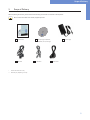
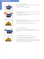
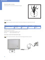
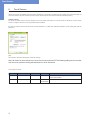
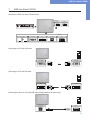
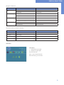
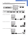
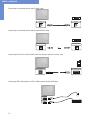
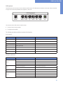
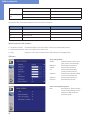
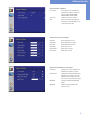
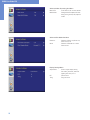
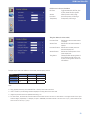
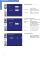
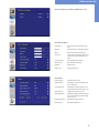
User Manual
SLIM-Line Series
201503_Manual_SLIM_Line_EN
SLIM-Line monitors for 48.3 cm
(19“) and 58.4 cm (23“)
DATA DISPLAY GROUP

Copyright
The contents of this manual are subject to change without notice.
© 2015 Data Display Group. All rights reserved.
Reproduction of this manual in parts or entirely without the previous authorization of Data Display Group is prohibited.
Data Display Group is not liable for errors and collateral or subsequent damage which result from supply, deployment or any other utilisation of this document.
All product names mentioned in this document are trademarks or registered trademarks of their due owners.
2

Table of Contents
1.
General Specifications................................................................................ 4
2.
Chassis Versions.......................................................................................... 4
3.
Scope of Delivery........................................................................................ 5
4.
General Safety Regulations........................................................................ 6
5.
First Installation........................................................................................... 9
6.
Touch Sensors............................................................................................ 12
7.
SLIM-Line Video P-ECOIII.......................................................................... 13
8.
SLIM-Line Video PIII.................................................................................. 17
9.Maintenance............................................................................................. 26
10. Guarantee / Service.................................................................................. 26
11.Disposal..................................................................................................... 28
12. Declaration of Conformity......................................................................... 29
3
General Specifications
1.
General Specifications
Scope of Document
This user manual is valid for POS-Line monitors up to 68 cm (27”). The POS-Line monitors are offered in different screen sizes and with
various controllers and other options.
Important note: This user manual is complemented by other additional documents when indicated.
All documents are also available for download from Data Display Group web site: www.datadisplay-group.com.
SLIM-Line monitor versions:
SLIM-Line Video P-ECOIII
Monitor with integrated AD converter board, 1 x RGB, 1 x DVI
SLIM-Line Video PIII:
Monitor with integrated AD converter board, 1 x RGB, 1 x DVI, S-Video, Composite Video
2.
Chassis Versions
For SLIM-line monitors are available as version with additional USB ports. This implies a deviation in the housing form. Options such
as glass or touch screen does not change the external appearance.
Version with extra USB ports on the back
sideview OSDFront view
4
Scope of Delivery
3.
Scope of Delivery
When unpacking the monitor, please check if the following accessories are included in the shipment:
Note: Pictures can differ from actually supplied products.
DATA DISPLAY GROUP
User manual
RGB cable
*
Devices with touch sensor only
**
Cable may vary depending on country
Accompanying-CD (Manuals,
Datasheets, Driver, Drawings)
USB cable*
Power supply
Power cable**
5
General Safety Regulations
4.
General Safety Regulations
Safety information
Please read this safety information carefully for your personal safety and for the prevention of property damage.
In case of a malfunction, immediately disconnect the power plug and contact your dealer or the next Data Display Group service centre. A malfunction is also considered if the housing, a control element or cable is damaged or if liquids or other objects penetrate the
monitor.
Please read the safety information carefully before installing the device. If you have any doubts about whether the device may be used
in a particular environment, please contact our service partner.
Repairs
Repairs may only be carried out by authorized technical personnel. Unauthorized access or improper repairs might cause serious property damage or cause danger to the user. In addition to that, any legitimate warranty claim expires.
Electrical connection
Disconnect the monitor from socket before executing any work. Do not touch or connect data cables or power cables during thunderstorms.
System start-up
Before the system start-up let the monitor adjust to the room temperature. Do not expose the device to direct heat sources. In case
of condensation, please wait a minimum of 12 hours before switching on the monitor. The monitor shall only be installed and used
according to this documentation data sheets. Only qualified personnel may perform the initial installation and system setup.
Qualified personnel
Qualified personnel, in terms of the safety information of this documentation, are persons who are qualified to activate, ground and
label devices, systems and circuits according to the safety standards.
Operation
For a proper and safe utilization of the product, adequate transportation, storage, installation, assembly, careful handling and maintenance are essential. The device is only certified for in-door operation. Extreme ambient conditions shall be avoided and the monitor
shall be protected from dust, humidity and heat. Do not expose the monitor to direct sunlight.
Transport
Unpack the monitor at the place of installation. Use only original packaging for transportation. Please observe these rules for any later
transport.
Condensation
Avoid condensation during transport at low temperatures or at extreme fluctuations of temperature.
6
General Safety Regulations
Safety guidelines for the handling of LCD monitors
• If the device is not used for a long period of time, unplug the power cable.
• Do not unplug the power cable while the device is powerd on, except for emergencies.
• To unplug the device without problems, sockets have to be easily accessible.
• Ensure that the power cable does not get pinched or kinked.
• Do not place heavy objects on the power cable.
• Do not use damaged or loose sockets to plug in the device.
• Plug the device in earthed sockets only.
• Operate the device with the power cables included in the delivery packet only.
• Use undamaged power cables only.
• When plugging in and out, do not touch the power cable with wet hands.
• Ensure that the power cable is plugged in the socket safely and correctly.
• Use for devices with external power supply only the supplied original power supply, or
an equivalent Low Power Source (LPS).
• Do not use extension block to plug several devices into a single socket.
• According to the size, devices may be difficult to handle and very heavy. Ensure that at
least two people lift and carry the device.
• Put down the device slowly and carefully to avoid damaging the LCD screen. Ensure that
the device stands stable.
• Keep packaging away from children. Danger of suffocation!
• Use our specified and professionally mounted wall mounting only.
• Do not put objects onto the device.
• Do not place candles, heaters or humidifier near the device.
• Keep the device away from fireplaces and flammable materials.
7
General Safety Regulations
• Ensure sufficient ventilation of the device.
• Keep a minimum distance of at least 10 mm devices to the wall, for devices with integrated PC of at least 40 mm.
• Ensure compliance with the operating temperature.
• Do not install the device in places where it is exposed to environmental impacts such
as rain or direct sunlight.
• Do not install the device in places where it is exposed to high humidity, dust or smoke.
In case of doubt, please contact your sales partner.
• Please use a soft, moist cloth for cleaning.
• For cleaning the screen, please use only commercially available screen cleaner. Do not
spray the cleaner directly to the device but onto a cloth.
• Please clean ventilation slots regularly to ensure a good air circulation.
• Protect your device from water splash.
• When cleaning, please make sure that no liquids get into the device.
• Screens and surfaces can be easily scratched. Therefore, please use the prescribed
cloth only.
• Caution high voltage! Never open the device by yourself.
• In case of unusual noises, burnt smell or smoke unplug the power cable.
• Do not insert objects into the device through the ventilation slots.
• If the same picture is displayed over a longer period of time, an after-image may arise.
• When exchanging batteries, pay attention to the polarity. Keep batteries away from
children and ensure an environmentally correct disposal.
8
First Installation
5.
First Installation
Position of connectors and controls
All the connectors for power and cables are located at the bottom of the back side of the display. The OSD keyboard is located left on
the back side (back view).
Position of the keys of the
OSD menus in the Video Series
Position of additional USB ports
(option only)
Position of the connectors for
power and signal cables
Mounting with VESA compliant monitor brackets
VESA-Befestigungspunkte
VESA mounting points
The SLIM-line monitors have an integrated VESA mounting.
The operating position of the device is perpendicular (90 degrees to the floor). For wall mounting, the permissible tilt angle is observed.
The device can be operated both in landscape mode and in portrait mode.
VESA formats:
19 “VESA 40 x 40/75 x 75
23 “VESA 40 x 40/75 x 75/200 x 200
9
First Installation
Allowed tilt angle for mounting
SLIM-line monitors can be mounted with the adjacent tilt angles..
monitor
0˚ to +180˚ 0˚ to -180˚
tilt angle
Connecting to Power
Note: All the POS-Line monitors requiring 12V DC power are shipped with an appropriate power supply.
Display
Input voltage
Output voltage
Output current
Power
Power supply for SLIM-Line
series
100-240 V AC
12V DC
5A
60 Watts
The power is connected to the display via the green female connector at the back side.
Specification of the power connector:
Female connector: Phoenix Contact DFK-MSTB-2,5 / 3-GF
Male plug:
Phoenix Contact MSTB 2,5 / 3-STF
Connecting to power with included power supply
Note: Connect the data cables to external devices before plugging the display to the power.
Power supply
12V nc GND
10
First Installation
All monitors with power supply have an adapter cable to connect the AC adapter. This cable is included in the scope of dfelivery.
• Connect the adapter cable to the display.
• Connect the adapter cable to the 12 V connector of the power supply.
• Insert the power cable into the power supply.
• Connect the power cable to a power socket.
Connecting to an existing power supply
Caution: The SLIMLine monitors with 12V DC operating power must only be connected to a low power source (according to
EN60950-1 chapter 2.5 „Low Power Source“).
Caution: The power source for POS-Line monitors with 12V DC operating power must not exceed the limit of 250 VA.
• Make sure that your external power supply is sufficient for the display. The maximum power consumption of the display is indicated
in the data sheet and the display label.
11
Touch Sensors
6.
Touch Sensors
SLIM-Line monitors are available with touch option. Depending on the panel size, different touch systems and touch technologies are
used. If the monitor has been ordered with touch option, the touch sensor and touch controller are installed at factory.
SLIM-Line Video:
The drivers for these monitors must be installed on your PC system. HID devices do not need drivers for Windows 7 and 8. Please
contact our support center if you are using LINUX based computers.
If a driver is required, the touch on this driver must be calibrated. Is it a HID Touch, Windows calibration in the control panel must be
performed.
path:
Control Panel \ All Control Panel Items \ Tablet PC Settings
Note: All drivers for the touch sensors can be found on the enclosed CD. The following table gives an overview
over the touch systems including web addresses for driver downloads.
Touch system overview:
Panel size
Touch technology
Manufacturer
Type
Driver download
19”
4-wire resistive
DMC
190A140A
http://www.datadisplay-group.de/service/downloads/
touch-treiber/#c9816
23”
AMR
eTurbo
SR30M182235D6
HID device, no driver required for Windows
12
SLIM-Line Video P-ECOIII
7.
SLIM-Line Video P-ECOIII
Connectors of POS-Line Video P-ECOIII series
optional
USB
USB
OSD Keyboard
Power
Menu Exit
—
+
n.c.
n.c.
LED
optional
Power supply
VGA (RGB)
DVI
USB (Touch)
USB
12V nc GND
Connecting to a PC with VGA cable
VGA (RGB)
VGA (RGB)
DVI
DVI
Connecting to a PC with DVI cable
Connecting the touch to a PC with USB cable (displays with touch sensor only)
USB (Touch)
USB
13
SLIM-Line Video P-ECOIII
Connecting USB cable (option) to a PC or different devices with USB cable
USB
USB
OSD keyboard
OSD functions of the monitor can be controlled via OSD key pad. The OSD allows selection of input source and fine tuning of various
functional parameters like brightness, contrast etc.
OSD Keyboard
Power
Menu Exit
—
+
n.c.
n.c.
The buttons of the OSD control can either be used:
• To access various functions directly
• To navigate within the OSD
The following two tables give an overview about the functions:
Direct functions:
Key
Function
Power
On/ Off
Menu
Open the OSD menu
Exit
Auto-adjustment
—
Open brightness control
+
Select signal input
n.c.
without function
n.c.
without function
14
Comment
for VGA
LED
SLIM-Line Video P-ECOIII
Navigation in OSD menu:
Key
Menu
—
+
Exit
Function
Comment
Open sub menu
when in main
Confirm entry
when in main
Cursor down
when in main or in sub menu
Cursor/ slider to the left
when in main or in sub menu
Cursor up
when in main or in sub menu
Cursor/ slider to the right
when in main or in sub menu
Leave OSD menu
when in main
Leave sub menu
when in sub menu
The LED show the current status of the board:
Color
Meaning
Green
Signal found
Green blink
Search signal
Red
Power safe mode
LED off
Monitor off
Remark
OSD menu
Input Select
1: Select VGA as input signal.
2: Select DVI as input signal.
Exit:Leave sub menu.
Press +/- keys to select sub menu.
Press menu key to go to sub menu.
15
SLIM-Line Video P-ECOIII
Display - Contrast
1: Adjust panel brightness.
2: Adjust panel contrast.
Exit:Leave sub menu.
Press +/- keys to select sub menu.
Press menu key to go to sub menu.
Color
1: Perform automatic color adjustment.
2: Set color space to sRGB.
3: Adjust color temperature manually.
Exit:Leave sub menu.
Press +/- keys to select sub menu.
Press menu key to go to sub menu.
Image
1: Perform automatic image optimization.
2: Adjust image width.
3: Adjust scanning spot of RGB signal.
4: Adjust image position in horizontal direction.
5: Adjust image position in vertical direction.
Exit:Leave sub menu.
Press +/- keys to select sub menu.
Press menu key to go to sub menu.
Tools
1: OSD adjustments for time out, position and direction (rotate, flip).
2: Reset all settings to factory defaults.
3: Reset all color settings to factory defaults.
4: Reset all position settings to factory defaults.
5: Adjust image sharpness.
6: Set DOS modes 640 / 720.
Exit:Leave sub menu.
Press +/- keys to select sub menu.
Press menu key to go to sub menu.
16
SLIM-Line Video PIII
8.
SLIM-Line Video PIII
Connectors and OSD buttons of POS-Line Video PIII series
optional
USB
USB
OSD Keyboard
Power
Menu Enter
Up
Down Left
Right
LED
optional
Power supply
VGA (RGB)
DVI
S-Video
Composite Video
USB (Touch)
USB
12V nc GND
Connecting to a PC with VGA cable
VGA (RGB)
VGA (RGB)
DVI
DVI
DVI
HDMI
Connecting to a PC with DVI cable
Connecting to a PC with DVI-HDMI cable
17
SLIM-Line Video PIII
Connecting to an external device with S-Video cable
S-Video
S-Video
Connecting to an external device with Composite Video cable
Composite Video
Composite Video
Connecting the Touch to a PC with USB cable (for displays with touch sensor only)
USB (Touch)
USB
Connecting USB cable (option) to a PC or different devices with USB cable
USB
USB
18
SLIM-Line Video PIII
OSD keyboard
The OSD functions of the monitor can be controlled via OSD key pad. The OSD allows the selection of the input source and the fine
tuning of various functional parameters like brightness, contrast etc.
OSD Keyboard
Power
Menu Enter
Up
Down Left
Right
LED
The six buttons of the OSD control can either be used:
• To access various functions directly
• To navigate within the OSD
The following two tables provide an overview of the functions:
Direct functions:
Key
Function
Power
On/ Off
Menu
Open the OSD menu
Enter
Confirm entry
Up
Select signal input
Down
Select PIP menu
Left
Without function
Right
Without function
Remark
if PIP/ PAP is activated, otherwice without function
Navigation in OSD menu:
Key
Menu
Enter
UP
Downt
Function
Remark
Close OSD menu
when in main
leave sub menu
when in sub menu
leave function
if function is selected
Open menu or sub menu
when in main or sub menu
Run selected function
if function is selected
Cursor up
when in main or sub menuu
Cursor down
when in main or sub menu
Select signal input
when in main or PIP menu
Open sub menu
when in main or sub menu
19
SLIM-Line Video PIII
Left
Right
Cursor to the left
when in sub menu
Reduce value of the slider
if slider is selected
Cursor to the right
when in sub menu
Increase value of the slider
if slider is selected
The green/red LEDs on the external keypad show the current status of the board:
Color
Meaning
Green
Signal found
Green blink
Search signal
Red
Power safe mode
LED off
Monitor off
Remark
Special functions of the controller:
• PIP (Picture in Picture):
Simultaneous display of two video sources on the screen with adjustable positions.
• PAP (Picture and Picture):Side-by-side display of two video sources.
• Tiling:
Display of a video source on several monitors with mutually non overlapping frames.
OSD menu
Image Settings Menu
Scheme: Brightness: Contrast: Hue: Saturation: Sharpness:
Advanced:
Switches between normal/ sport/
game/ cinema/ vivid presettings.
Panel brightness adjustment.
Panel contrast adjustment.
Panel HUE adjustment (RGB,
S-Video and Composite) only.
Panel saturation adjustment (RGB, S-Video and Composite) only.
Panel sharpness adjustment.
Open Advanced sub menu.
Advanced Image Settings Menu
Note: 20
Noise Reduction, Video Processing
and Film Mode & Scaling are only
available for RGB, S-Video and
Composite signals.
SLIM-Line Video PIII
Advanced Color Sub Menu
Color Temp: User Color:
ADC:
Allow selection of different color
temperature schemes. Selections
are user, sRGB, 4200K, 5000K,
5400K, 6500K, 7200K, 9300K.
Create custom color scheme.
Auto Color-Adjust. Performs auto
fine tuning on the ADC (RGB, S-Video and Composite only).
Advanced User Color Sub Menu
Red Gain:
Green Gain:
Blue Gain:
Red Offset:
Green Offset:
Blue Offset:
Boost adjustment on red.
Boost adjustment on green.
Boost adjustment on blue.
Offset level on red.
Offset level on green.
Offset level on blue.
Advanced Noise Reduction Sub Menu
CCS Mode:
Dynamic NR:
MPEG NR:
MPEG NR:
Changes Cross-Color Suppression
between off/ adaptive/ normal.
Changes Dynamic Noise Reduction
between low/ medium/ high/ off/
adaptive. High setting may cause
loss of detail, adjust for best image.
Enables/ disables the MPEG NR
Mode.
Manual setting of MPEG noise
reduction level.
21
SLIM-Line Video PIII
Advanced Video Processing Sub Menu
Main DCDi:
MADI Mode:
Turns DCDi on/ off on main channel.
Changes Motion Adaptive De-Interlacing among normal/ off/ adaptive
modes.
Advanced Film Mode Sub Menu
Detection:
Mode:
Selection of Video-3:2/ Video-2:2/
Video-3:2-2:2/ off.
Selection of Normal 3:2 or other
future modes.
Display Settings Menü
Aspect Ratio: PIP:
Tiling:
22
Used to adjust display among
full screen, panoramic, letter box
expand, pillar box, and 1:1.
PIP sub menu.
Tiling sub menu.
SLIM-Line Video PIII
PIP (Picture in Picture) Sub Menu
PIP mode:
Vertical:
Horizontal
Transparency: Toggle between Off, PAP-Tall, Sideby-Side, Small PIP and Large PIP.
Vertical position of PIP image.
Horizontal position of PIP image.
Transparency of PIP image.
Tiling Sub Menu (for video walls)
Horizontal Total: Defines the total horizontal number
of displays.
Vertical Total:
Defines the total vertical number of
displays.
Horizontal Position: Defines the horizontal position of
the actual display unit.
Vertical Position: Defines the vertical position of the
actual display unit.
Tiling Status:
Enables/disables the tiling function. If the PIP-Mode is PAP-Tall or sideby-side, the tiling status will be off
and disabled.
Example: 3 by 3 video wall: Definition of horizontal/ vertical display position:
Position
1
2
1
1
1/1
2/1
3/1
2
1/2
2/2
3/2
3
1/3
2/3
3/3
Note:
• Tiling property cannot be used while PAP-Tall or Side-by-Side modes are active.
• If PIP is turned on, the PIP image would be displayed on every panel of the video wall.
• Image and position menus are disabled while tiling is on.
• For best results, the Horizontal Total and Vertical Total value should to be set to a value which is an integer divider of the input
width or height, respectively. For example, if input is 1280x768, horizontal total has to be set to one of 2, 4, 5, 8 and vertical total
has to be set to one of 2, 3, 4, 6, 8.
23
SLIM-Line Video PIII
Position Settings Menu (for HDMI, S-Video and
Component Video Signals)
Width:
Height:
Horizontal Start:
Vertical Start:
Adjusts total width of the image by
stretching or shrinking.
Adjusts total height of the image by
stretching or shrinking.
Changes the starting point of the
image horizontally, without altering
height.
Changes the starting point of the
image vertically, without altering
width.
Position Settings Menu (for RGB)
Auto Adjust:
Image Position.:
Phase:
Clocks/Line:
Advanced:
Performs auto-adjust function on the
image.
Image position sub menu.
Slider to adjust the sampling phase
of the analogue interface. For
optimum image quality, input pixels
should be sampled at the ideal
sampling points.
Slider to adjust the sample clock of
the analogue interface. This is helpful for improving the image quality
for non-standard display modes.
Advanced Settings sub menu.
Advanced Settings Sub Menu
Note:
24
This function can be used to manually force some of the widely used
difficult-to-detect modes which can
be misinterpreted by the controller.
SLIM-Line Video PIII
Advanced Settings Sub Menu (HDMI mode only)
OSD Settings Menu
Horizontal:
Vertical: Blend: Time Out: Horizontal Flip: Vertical Flip:
Rotation:
OSD Zoom:
Move the OSD in horizontal direction.
Move the OSD in vertical direction.
OSD transparency adjustment.
This function determines after how
many seconds the OSD will close
itself.
Flips the OSD horizontally.
Flips the OSD vertically.
Rotates OSD.
Changes OSD size.
Setup Menu
Factory Reset:
Speed Mode:
Execute factory reset.
In graphics mode, fast image transfer is supported.
Show Menu Of:
Changes the menu between main
image and PIP if the PIP mode is on.
Input Search:
Toggles input search on/ off.
Auto Brightness: (Optional) Toggles automatic brightness control through external light
sensor on/ off.
Firmware Version: Installed Firmware Version.
OSD Version:
Installed OSD Version.
25
Maintenance
9.
Maintenance
Systems with active cooling require cleaning of ventilation slots every 6 months. Systems with passive cooling must be cleaned every
12 months.
10.
Guarantee / Service
Guarantee
Data Display Group grants a manufacturer‘s guarantee of two years from the date of delivery.
The rendering of guarantee claims shall neither extend nor restart the guarantee period.
During the guarantee period, Data Display Group shall repair product faults based on material or production defects. The guarantee
service is executed at Data Display Group‘s discretion through repair, replacement of defective parts or by exchanging a product for a
product of equal quality without charging the customer for material or labor.
Guarantee claims are only accepted, if Data Display Group receives notification of a defective product within the guarantee period
and the product is presented to the Data Display Group Service Centre together with all information as specified in the RMA process.
Guarantee Exclusions and Limitations
This guarantee does not apply to any defect for which Data Display group is not responsible and which includes, but is not limited to
the following:
• Unauthorized opening or disassembling of the product
• Faulty maintenance by non-observation of maintenance instructions
• Inappropriate storage or cleaning of the product
• Unauthorized modification of the product
• Incorrect use or misuse
• Non-observation of operating and installation instructions
• Permanent display of fixed images (causing image retention or image sticking)
• Operating the product in conditions which exceed the limitations of the specification
• Use of inappropriate boxes, packaging or modes of shipment
• Force majeure like fire, acts of war, acts of violence, chemical or biological impacts, lightning strikes, over voltage or
similar events
• Fault resulting from the use of software which was not originally supplied with the product or which is incorrectly installed
• Normal wear and tear and wearing parts (i.e. LCD panel)
Mechanical damages like scratches, pressure or break points are excluded from this guarantee.
This guarantee does not include accessory parts which are not integral part of the product (as boxes, batteries).
Pixel errors only constitute a fault under the terms of this guarantee if they deviate from the product specification (i.e. ISO 9241-307
pixel failure class II).
26
Guarantee / Service
Display Quality - Prevention of after image burn in effects
After image burn-in means that an image or part of an image (i.e. logo) remains visible on the screen even if the image on the screen
is changed. This should not occur if the LCD panel is operated in normal conditions with changing content. To prevent burn-in effects
please follow the following guidelines.
• Do not display fixed patterns for an extended time period of more then 12 hours.
• Power-off the monitor for 4 hours after using it for 20 hours, and for 2 hours after using it for 12 hours.
• Use the power scheme and power management of the PC.
• Use plain-colored screen savers.
• Avoid patterns with a strong difference in brightness and contrast.
• Avoid gray colors.
• Change images and logos regularly. Show animated pictures for 60 seconds after 4 hours of operation.
• The best way to protect your display is to switch the monitor off when not in use or to use screen savers.
Non-observance of these guidelines may have effects on warranty.
Guarantee Processing
Group RMA process. In order to avoid unnecessary charges, it is important to adhere to the RMA regulations.
Products must be appropriately and professionally packed for a safe return to the Data Display Group Service Centre. Products with
panel sizes equal or larger then 81 cm (32“) must be shipped on pallets in upright position.
Data Display Group does not assume liability for any customer data stored on products which are returned to Data Display Group.
Limitations of Liability and Benefits
With this guarantee declaration, Data Display Group exclusively guarantees that the product is free of material and manufacturing
faults.
Data Display Group does not issue any other guarantee or similar statements other than this declaration.
This guarantee does not impair or affect a buyer‘s statutory claim against the seller due to material damage. Such claims can be asserted instead of the guarantee agreed to here at the buyer’s discretion.
Mandatory legal rights and mandatory claims under the German Product liability remain unaffected.
Applicable Law and Place of Jurisdiction
The laws of the Federal Republic of Germany apply.
Place of jurisdiction is Munich.
27
Disposal
Service addresses
Germany
Distec GmbH
Augsburger Str. 2b
D-82110 Germering
T +49 (0)89 / 89 43 63 0
B [email protected]
England
Display Technology Ltd.
5 The Oaks Business Village
Revenge Road, Lordswood
Chatham, Kent, ME5 8LF
T +44 (0)16 34 / 67 27 55
B [email protected]
USA
Apollo Corp.
87 Raynor Avenue, Unit 1
Ronkonkoma NY 11779
T +1 (1)631 / 580-4360
B [email protected]
Please go to the following web address for further information about our RMA regulations and RMA forms:
Http://www.datadisplay-group.com/service
11.
Disposal
Disposal of old devices
If the acquired Distec product is to be disposed of, must be implemented into national law the Directive
“2012/19 / EU”.
Disposal of batteries
Applicable in all countries of the EU and in countries with separate battery collection systems.
The Batteries in this product should not be disposed with other household waste. The chemical symbol
Pb, CD or Hg indicate that the battery contains lead, cadmium or mercury above the reference level in EC
directive 2006/66.
Batteries which are not disposed correctly can cause harm environment and health.
Our environment is close to our hearts. Please help us to protect our environment and recycle empty batteries with the free battery
collection system.
28
Declaration of Conformity
12.
Declaration of Conformity
C
EC Declaration of Conformity
Address:
Distec GmbH
Augsburger Str. 2B
82110 Germering, Germany
Product:
SLIM-Line display series Video-PECOIII, Video-PIII
Model:
19.0”: DS-90-538; DS-90-539; DS-91-520; DS-91-339; DS-90-861; DS-90-862; DS-91-214; DS-91-215 DS-90-909; DS-91-393
23.0”: DS-91-152; DS-91-185; DS-91-404; DS-91-228; DS-91-229
The product is in compliance with the requirements of the following European directives:
Main Unit:
2004/108/EG
2006/95/EG
2011/65/EU
Electromagnetic Compatibility (EMC)
Low Voltage Directive (LVD)
Restriction of the use of certain hazardous substances in electrical
and electronic equipment (RoHS)
RF Unit (displays with WLAN only):
1999/5/EG
)2011/65/EU
Radio and Telecommunications Terminal Equipment (R&TTE)
Restriction of the use of certain hazardous substances in electrical
and electronic equipment (RoHS)
The compliance with the requirements of the European Directives was proved by the application of the following harmonised
standards:
Main Unit
EMV
EN 55022:2010 +AC:2011
EN 55024:2010
EN 61000-3-2:2006 +A1:2009 +A2:2009
EN 61000-3-3:2008
NSR
EN 60950-1:2006 +A11:2009 +A1:2010 +AC:2011 +A12:2011
RoHS
EN 50581:2012
Year of CE marking2013
RF Unit (displays with WLAN only):
R&TTE
EN 301 489-1 V1.9.2 (2011-09)
EN 301 489-17 V2.2.1 (2012-09)
EN 300 328 V1.8.1 (2012-06)
NSR
EN 60950-1:2006 +A11:2009 +A1:2010 +AC:2011 +A12:2011
29
Declaration of Conformity
Exposition von Personen
EN 62479:2010
RoHS
EN 50581:2012
The object of the declaration described above is in conformity with Directive 2011/65/EU of the European Parliament and of the
Council of 8 June 2011on the restriction of the use of certain hazardous substances in electrical and electronic equipment.
Germering, 19.12.2013
_________________________________________
Werner Schubert, Geschäftsführung
FCC-Declaration of conformity
This equipment has been tested and found to comply with the limits for a Class A digital device, pursuant to Part 15 of the FCC Rules.
These limits are designed to provide reasonable protection against harmful interference when the equipment is operated in a commercial environment. This equipment generates, uses and can radiate radio frequency energy and, if not installed and used in accordance
with the instruction manual, may cause harmful interference to radio communications. Operation of this equipment in a residential area
is likely to cause harmful interference in which case the user will be required to correct the interference at his own expense.
Canadian Department of Communications Compliance Statement
This Class A digital apparatus meets all requirements of the Canadian Interference-Causing Equipment Regulations.
Observation des normes-Class A - Cet appareil numérique de la classe B est conforme à la norme NMB-003 du Canada.
FCC Information:
• Changes or modifications not expressly approved by Distec GmbH could void the user’s authority to operate the equipment.
• Use the attached specified cables with the POS-Line monitor so as not to interfere with radio and television reception.
• Please use the supplied power cord or equivalent to ensure FCC compliance.
• Please use the supplied shielded video signal cable, Mini D-SUB 15 pin to Mini D-SUB.
30


![4403002491_712_716 menu_EN_A [s]](http://vs1.manualzilla.com/store/data/005650300_1-96030b29e24dd373b0bced3bef593dda-150x150.png)