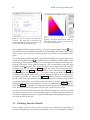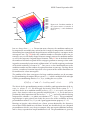
1
SESES Tutorial September 2012
115
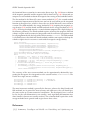
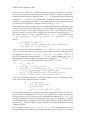
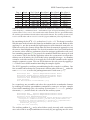
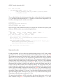
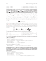
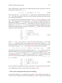
Next the material parameters of Nd:YAG (NdYAG) and undoped YAG (Cap) are specified.
MaterialSpec Cap
Equation ThermalEnergy Elasticity Enable
Parameter StressOrtho
LinElastIso(Emodule 307 GPa; PoissonR 0.3;
AlphaIso -1.78e-6*(Temp-Tair)+1.65e-8*(Temp*Temp-Tair*Tair)) SIunit
Parameter Refrac
1.82
Parameter KappaIso D_Temp 1.9e8/pow(log(5.33*Temp),7.14)-331e2/Temp,
331e2/(Temp*Temp)-(1.9e8*7.14)/
(Temp*pow(log(5.33*Temp),8.14)) W/(m*K)-W/(m*K**2)
MaterialSpec NdYAG From Cap
Parameter Heat conv*P*(Pump(x,y,w0,M,lambda,alpha,ref)
+ Pump(x,-y+l,w0,M,lambda,alpha,ref)) W/m**3
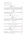
We start with YAG and since we model both for the temperature and the mechanical displacement, we have to enable their computation with the Equation statement.
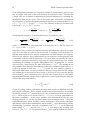
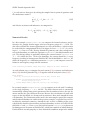
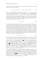
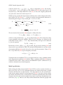
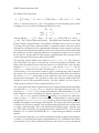
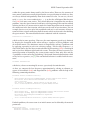
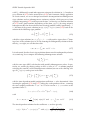
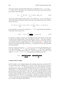
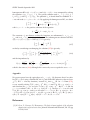
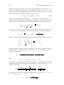
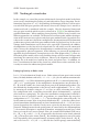
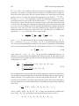
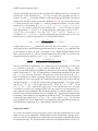
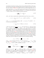
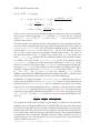
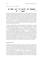
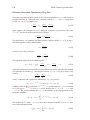
The heat conductivity κ and the thermal expansion δℓ/ℓ0 are functions of the temperature T and following [6] we use the models
κ=
and
331×102 W
1.9×10⁸
,
−
T
mK2
(log(5.33 T )) 7.14
δℓ
= −1.78×10⁻⁶ (T − T0 ) + 1.65×10⁻⁸ (T 2 − T02 ) ,
ℓ0
(2.97)
(2.98)
with [T ] = K. The parameters Emodule, PoissonR, and Refrac denote Young’s
modulus E, the Poisson’s ratio ν and the refractive index n0 . The parameter DRefrac
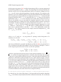
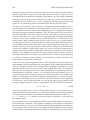
denotes the change of the refractive index ∆n as a function of the temperature following (2.90). Here, we assume the thermal dispersion ∂n/∂T to be a constant so
that (2.90) can be rewritten as ∆n = (T − T0 )∂n/∂T . Next we define the Nd:YAG
material as inheriting all properties from YAG and by additionally defining the heat
source. The routine Pump is a user routine defined following (2.94), (2.95) and (2.96).
The first call is for the pumping from the left side and the second call for the pump
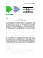
beam from the right side of the rod. We then build the macro element mesh and map
two materials onto the macro element mesh.
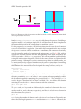
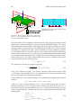
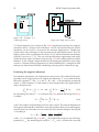
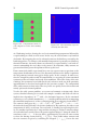
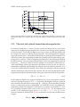
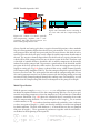
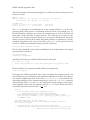
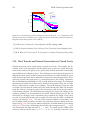
The thermal and mechanical boundary conditions are then next. The front and the
back surface of the rod are in contact with air, defined by the boundary condition BC
Air. The cylindrical surface of the rod is assumed to be in direct contact with the cooling water define by the boundary condition BC Water. As we have assumed a radial
symmetric situation, the longitudinal axis of the crystal is automatically fixed for deformations in the radial direction. Further we assume the rod to be free to expand.
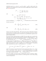
Therefore we have only to fix one point of the rod for displacements in the longitudinal direction. Therefore we fix the point in the center of the rod by the boundary
condition
BC Fixed
0 nytot/2 JType 0 Dirichlet Disp.Y 0 m
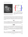
The command section of the input file starts with some settings concerning the used
solver and desired information on the output stream during execution of the kernel
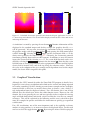
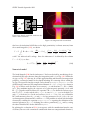
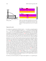
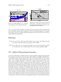
program. Then several one-dimensional lattices for the OPD evaluation are defined
with a For loop statement. Here we define straight lines along the pump lasing direction where the local OPD will be integrated.