1
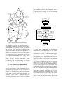
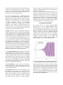
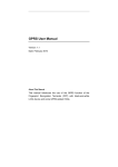
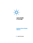
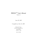
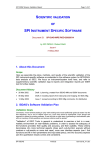
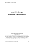
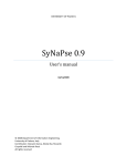
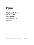
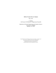
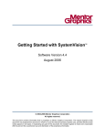
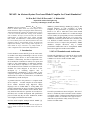
MCAST: An Abstract-Syntax-Tree based Model Compiler for Circuit Simulation*
Bo Wan, Bo P. Hu, Lili Zhou, and C. -J. Richard Shi
Department of Electrical Engineering
University of Washington, Seattle, WA 98195
Abstract:*This paper introduces MCAST: a Model Compiler--based on Abstract Syntax Trees---that reads compact device
models described in high-level languages VHDL-AMS/VerilogAMS and automatically generates the simulator device code in
C that can be directly linked with existing circuit simulators
such as SPICE3. We report, for the first time, the successful
implementation of industry-grade device models, including
EKV, BSIM, and BSIM-SOI, in VHDL-AMS/Verilog-AMS.
For a set of industry test circuits, MCAST yields the exact same
simulation results as, and comparable speed to, the model code
implemented manually, while existing model compilers are
either limited in scope, restricted to very simple models, or
orders of magnitude slower than manual implementations.
1. Introduction
Circuit simulators such as SPICE [7] are the corner stone
of modern VLSI design methodologies. The use of such
simulators requires devices to have models built in the
simulators. Unfortunately, the effort to implement a new
device model into a simulator is tedious, error prone, and
requires a deep understanding of underlying simulator
code. As the result, it only takes 1 to 2 years for a new
device model to become available in a commercial circuit
simulator for circuit designers to use after it is first
developed by a modeling engineer. Due to
implementation considerations, a device model is only
completely defined by its implementation in a simulator,
which means it is either not, or hard to be, accessible and
maintainable by model developers.
A potential solution to this problem is a compact model
device compiler. A model compiler can read compact
device models described using high-level design
languages such as VHDL-AMS or Verilog-AMS, and
generate automatically the device simulator code that can
be linked with a circuit simulator such as SPICE. Since
only behavior-related device equations are needed to be
described, such a model development and qualification
process can take only days to weeks. Furthermore, models
will be highly maintainable and reusable.
Previous model compiler attempts include ADMIT [2],
*
This research was supported by DARPA NeoCAD Program under
Grant No. N66001-01-8920 and NSF CAREER Award under Grant No.
9985507.
iSMILE [3], MAST/Saber[9], ADMS [4], [5] and [6]. The
principal difficulty of wide acceptance of model
compilers is the performance of generated code. It is
known to be 100 to 1000 times slower than manual
implementation even for MOS Level 1 model and simple
circuits. Further, the speed penalty increases with both the
complexity of a model and the size of a circuit [10].
ADMS uses a build-in symbolic derivative calculator, and
it is difficult to handle constructs like loops, if-then,
subroutine call etc. To improve the performance, ADMS
introduces compiler derivatives; only a limited
performance enhancement can be accomplished. ADMS
has not been applied to models such as BSIM.
2. MCAST Foundation and Architecture
The MCAST foundation is to represent the device model
written in VHDL-AMS using AST. For example, below
is MOS Level 1 device model in VHDL-AMS.
Vgstmp := Vg – Vs;
Vdstmp := Vd – Vs;
Vgdtmp := Vgstmp – Vdstmp;
IF Vdstmp >= 0 THEN
Forward := 1;
Vds := Vdstmp;
Vgs := Vgstmp;
ELSE
Forward := -1;
Vds := - Vdstmp;
Vgs := Vgdtmp;
END IF;
-- forward mode
-- reverse mode
IF Vgs <= Vth THEN
-- cut off
Idstmp := 0.0;
ELSE
IF Vgs-Vth <= Vds THEN -- saturation
Idstmp := Beta * (((Vgs -Vth)**2)/2);
ELSE -- triode
Idstmp := Beta*((Vgs-Vth)
*Vds((Vds**2)/2));
END IF;
END IF;
Ids := Forward * Idstmp;
The AST representation is shown in Figure 1. The root of
the tree is variable Ids, where leaf nodes can be constants
or terminal voltages. Different from traditional AST used
in computer science, we introduce a new type of Switch
(SW) node to represent the widely used if-else-endif
structure in VHDL-AMS.
can involve potentially hundreds of parameters, variables
and intermediate variables, and thousands of lines of
equations. Our effort has been focused primarily on how
to generate element stamping code that uses minimum
amount of computations over the entire simulation run.
ids
*
Forward
SW1
Condition Tree
(Vgs<Vth)
SW2
-1
0.0
1
SW3
Condition Tree
(Vgs-Vth<=Vds)
*
*
-
/
Beta
VHDL-AMS device
source code
VHDL-AMS parser
*
**
/
2.0
-
2.0
Vgs
SW4
Intermedicate
Format
*
*
Vth
Vds
SW5
2.0
Auto-Differentiation, Auto-Element
Stamping, AST construction
2.0
Optimizations
Condition Tree
(Vdstmp>0)
-
Constant
Node
Propogation
*
Vg
Vgstmp
Vs
Node
Reduction
Optimization
Core
Node
Sharing
Vgdtmp
ByPass
-1
-
Green Node
Optimization
-
Other
techniques
Vdstmp
Code Generation
Vd
Figure 1. An AST example for MOS Level 1 model.
The architecture of MCAST is depicted in Figure 2. It
starts from the VHDL-AMS description file of a device
model. MCAST first parses the input file, checks errors
and stores the device information in an intermediate
format structure. Then the AST tree representation of
device models and the needed derivatives are constructed,
and derivatives are generated by automatic differentiation.
Next, techniques are used to optimize the AST for both
device equations and their derivatives. Finally, device
codes that include device definition, device setup, device
loading, derivative calculation and matrix element
stamping, interfaces to the target simulator, truncation
error checking, and convergence limiting are generated
from the optimized AST.
3. AST-Driven Code Optimization
The success of a model compiler depends critically on the
efficiency and robustness of the generated device code,
more specifically, the portion of code responsible for
filling in the Jacobian matrices and the right-hand-side
vectors. This so-called element stamping consists of
device model evaluation, equivalent conductance and
equivalent current source evaluation (derivative
derivations). High fidelity device models such as BSIM
C/C++
device files
Figure 2. MCAST model compiler architecture.
Green Node Optimization: A straightforward
implementation of element stamping, as done in most
existing model compilers, is to use automatic
differentiation to generate the code for element stamping
and incorporate the code directly for solving systems of
linear equations at every nonlinear iteration of each time
point. This is equivalent to evaluating the AST at every
iteration. In contrast, MCAST colors the AST into three
colors: green (the node needed to be evaluated only once
over the entire simulation), purple (the code needed to
evaluated once at each time point, and red (the code
needed to be evaluated at every nonlinear iteration of
each time point). Special cases of green nodes include
model/instance parameter calculation and range checking.
This can be substantial for models like BSIM that have
hundreds of parameters. Examples of purple nodes
include those calculating performances such as power
consumption (multiplying currents and voltages at every
time point). Red nodes include examples such as those
device equations whose terminal voltages changed at each
iteration. With AST, MCAST identifies automatically
A.
green nodes by a bottom up traversal of the AST to check
on how each node depends on leaf nodes (constants,
parameters, or variables), and purple nodes by a top down
travel of the AST to check if a node is required at every
iteration or only once at each time point.
We note that exploring these computational latency
manually was instrumental to the success of SPICE over
general-purpose numerical simulators. MAST/Saber from
Analogy [9] and ADMS [4] use specific language
constructs or compiler derivatives for a model developer
to indicate parameter checking or performance
calculation. This still puts a huge burden on model
developers, and makes the model description less
readable. Further, only limited amount of optimization
can be achieved. As the result, MAST/Saber has achieved
a limited success for semiconductor circuits.
B. Bypass: MCAST employs automatically node bypass
and device bypass. MCAST uses Automatic Differentiation
in the generation of the Jacobian Matrix elements
associated with the device, automatic differentiation may
generate large amount of intermediate dummy nodes that
are just associated with the dumb operations with +0, -0,
*0, *1,*-1. These nodes can be bypassed or compressed in
code generation. Device bypass is a well-known method
first implemented in SPICE2 [7]. It offers a reduction by
allowing previously calculated results to be used again for
current iteration, when the terminal voltages/currents of the
device of current iteration have not changed over a limit
from its previous value (often, this limit is set empirically).
Otherwise, this device would have to be re-evaluated.
MCAST incorporated device bypass automatically.
C. Constant Propagation: Model designers often define
some frequently used constants for the new device in
VHDL-AMS file, such as kTq, CONSTvt0, etc in BSIM3,
to make the VHDL-AMS source file easier to understand
and maintain, they also may define some new constants
based on those already defined constants. Thee constants
are necessary for the readability of the source VHDL-AMS
code. MCAST will detect those as constants and replace
them by values during code generation.
D. Node Reduction: If some nodes do not affect the
element stamping, these nodes are redundant, and can be
removed from the AST. This case often occurs at the early
stage of model evaluation.
E. Node Sharing: MCAST uses pattern matching to find
the duplicate sub-expression trees inside an AST.
Different from classical ASTs where such duplicates are
always shared, MCAST AST has conditional Switch
(SW) nodes, and such duplicates can only be shared if
their parent nodes have the same or similar conditions.
MCAST categories these duplicates based on their
conditions and computational costs, and determines if
they are to be shared or not.
We note that green node optimization and bypass are
specific to model compilers and are for the first time
automated in MCAST. The other three techniques are
well known in compiler theory. However, with automatic
differentiation for derivative calculation used in compiler
compilers, these features as in VHDL-AMS/VerilogAMS will not be able to be recognized by the C compilers
from the generated C code from model compilers.
4. Experimental Results
Five existing and two new device models including
MOSFET level 1, level 3, BSIM3, BSIMSOI, EKV,
Thermal-Electrical and Opto-Electrical device models
have been implemented with MCAST, and lined with
Berkeley SPICE3, and tested on thirteen benchmark
circuits. For all the circuits, the simulation using the
compiled models generated by MCAST from VHDLAMS yields the same results as that implemented
manually in Berkeley SPICE3. As an example, the
simulation results of a voltage-controlled oscillator are
shown in Figure 3: the two curves match perfectly.
Figure 3. The simulation results of VCO using the MCAST-compiled
BSIM3 model and the manually implemented BSIM3 model.
MCAST generated device codes are linked to SPICE3
source code to compare with human optimized codes
(existing built-in device model codes in SPICE3). Figure
4 shows the speed comparison on benchmark circuits for
MOSFET level 3 and BSIM. MCAST Level 3 model
code is 10%-100% faster than the hand codes (except for
one circuit), MCAST BSIM code is less than 70% slower
than human optimized BSIM code.
MCAST runtime
2
5. Conclusions
1.5
1
0.5
0
1 2 3 4 5 6 7 8 9 10 11 12 13 14
benchmark circuits
MOSFET BSIM3
MOSFET Level 3
We presented MCAST---a model compiler that can
automatically compile compact device models in highlevel modeling language VHDL-AMS into the simulator
code such as SPICE. Several industry-grade device
models including EKV, BSIM, and BSIM-SOI have been
implemented using MCAST. Simulation of a set of
industry circuits has shown that MCAST has the same
accuracy and comparable performance as human
optimized device code. Further, MCAST scales with the
size of circuits. In addition, two mixed-technologies
(thermal-electro-optical) device models were successfully
implemented.
Figure 4. The speed ratios of MCAST-compiled vs manually
optimized device codes.
We compare SPICE3 integrated with MCAST generated
BSIM3 model with the best commercially available
VHDL-AMS/Verilog-AMS simulator** on adders with
increasing number of bits. The results are shown in Figure
5. Our model compiler with AST-driven optimization is
two to three orders of magnitude faster than the
commercial behavioral simulator. Furthermore, our
approach scales linearly with the size of a circuit, where
the cost of the commercial simulator increases
exponentially. This demonstrates that the MCAST
technology is especially suitable to handle large circuits.
Figure 6. The speedup breakdown of various optimization
techniques.
Speed Comparison
Simulation Time(s)
100000
References
10000
[1]
1000
100
10
1
1bit
2bit
3bit
4bit
5bit
6bit
8bit
Adder Circuits
BMAC-BSIM3
Commertial Behavior Model Simulator
Figure 5. Speed comparison of MCAST-BSIM3 and a commercial
behavior model simulator.
Figure 6 shows the speedup breakdowns of different
optimization techniques over thirteen benchmark circuits,
in terms of device evaluation time per iteration. The
overall speed up is about 4 to 5 times, where green node
optimization achieves a speed up of about 3.5, and an
average 50% for other techniques.
**
We attempted all the existing commercial behavioral simulators, and
the one used here is from a leading vendor and has the best performance
comparing to other simulators.
Ken Kundert, “Automatic Model Compilation – An Idea Whose
Time Has Come”, The Designer’s Guide, May 2002.
[2] S. Liu, K.C.Hsu, P.Subramaniam, “ADMIT-ADVICE Modeling
Interface Tool”, IEEE Custom Integrated Circuits Conference,
1988
[3] A.T.Yang, and S.M.Kang, “iSMILE: A Novel Circuit Simulation
Program with emphasis on New Device Model Development”, 26th
Design Automation Conference, 1989
[4] Laurant Lemaitre, Colin McAndrew, and Steve Hamm, “ADMSAutomatic Device Model Synthesizer”, IEEE Custom Integrated
Circuits Conference, May 2002
[5] R. V. H. Booth, “An Extensible Compact Model Description
Language and Compiler”, Proc. IEEE BMAS, pp. 39-44, Oct. 2001.
[6] M. Zorzi, N. Speciale, G. Masetti, “Automatic Embedding of a
Ferro-electric Capacitor Model in Eldo”, Proc. IEEE BMAS, Oct.
2001
[7] L. W. Nagel, “SPICE2 – A computer program to simulate
semiconductor circuits, “ Univ. of California, Berkeley, ERL
Memo ERL-M520, May 1975.
[8] Y. Cheng and C. Hu, MOSFET Modeling & BSIM3 User’s Guide,
Kluwer Academic Publisher, 1999
[9] MAST/Saber User Manual, Analogy Inc.
[10] Prof. Hal Carter, “Modeling and Simulating Semiconductor
Devices Using VHDL-AMS”, BMAS 2000