1
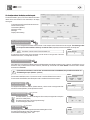
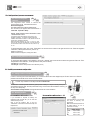
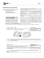
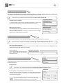
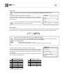
User Manual
Pressure • Temperature • Humidity • Air Velocity • Airflow • Sound level
New
LCC-300 software
User manual
Configuration software
for Class 200/300 and displays
units - ranges - relays - set points - alarms
analogue outputs - channels - regulations
Summary
I - Minimum System Requirements
I 1 - Minimum recommended configuration . . . . . . . . . . . . . . . . . . . . . . . . . . . . . . . . . . . . . . . . . . . . . . . . . . . . . . . . . . . . . . . . . . . . . p 2
I 2 - Installing the software . . . . . . . . . . . . . . . . . . . . . . . . . . . . . . . . . . . . . . . . . . . . . . . . . . . . . . . . . . . . . . . . . . . . . . . . . . . . . . . . . . . . . . . . . . . . p 2
I 3 - Uninstalling the software . . . . . . . . . . . . . . . . . . . . . . . . . . . . . . . . . . . . . . . . . . . . . . . . . . . . . . . . . . . . . . . . . . . . . . . . . . . . . . . . . . . . . . . . p 2
I 4 - Launching the software . . . . . . . . . . . . . . . . . . . . . . . . . . . . . . . . . . . . . . . . . . . . . . . . . . . . . . . . . . . . . . . . . . . . . . . . . . . . . . . . . . . . . . . . . . p 2
II - Connecting the transmitter . . . . . . . . . . . . . . . . . . . . . . . . . . . . . . . . . . . . . . . . . . . . . . . . . . . . . . . . . . . . . . . . . . . . . . . . . . . . . . . . . . . . . . . . . . . . . . . . . . . p 2
III - Configuration of the transmitter
III 1 - Principle . . . . . . . . . . . . . . . . . . . . . . . . . . . . . . . . . . . . . . . . . . . . . . . . . . . . . . . . . . . . . . . . . . . . . . . . . . . . . . . . . . . . . . . . . . . . . . . . . . . . . . . . . . . . . p 3
III 2 - Configuration of the display and keypad . . . . . . . . . . . . . . . . . . . . . . . . . . . . . . . . . . . . . . . . . . . . . . . . . . . . . . . . . . . . . . . . . p 4
III 2a - Channel of the transmitter for the infrared remote control . . . . . . . . . . . . . . . . . . . . . . . . . . . . . . . . . . . p 4
III 2b - RS 232 communication . . . . . . . . . . . . . . . . . . . . . . . . . . . . . . . . . . . . . . . . . . . . . . . . . . . . . . . . . . . . . . . . . . . . . . . . . . . . . . . p 4
III 2c - Slave address . . . . . . . . . . . . . . . . . . . . . . . . . . . . . . . . . . . . . . . . . . . . . . . . . . . . . . . . . . . . . . . . . . . . . . . . . . . . . . . . . . . . . . . . . . . p 4
III 2d - Locking the keyboard . . . . . . . . . . . . . . . . . . . . . . . . . . . . . . . . . . . . . . . . . . . . . . . . . . . . . . . . . . . . . . . . . . . . . . . . . . . . . . . . . . p 4
III 2e - Backlight . . . . . . . . . . . . . . . . . . . . . . . . . . . . . . . . . . . . . . . . . . . . . . . . . . . . . . . . . . . . . . . . . . . . . . . . . . . . . . . . . . . . . . . . . . . . . . . . . . p 4
III 2f - Display contrast setting . . . . . . . . . . . . . . . . . . . . . . . . . . . . . . . . . . . . . . . . . . . . . . . . . . . . . . . . . . . . . . . . . . . . . . . . . . . . . . . p 5
III 3 - Configuration of the channels and units of measurement . . . . . . . . . . . . . . . . . . . . . . . . . . . . . . . . . . . . . . . . . p 5
III 3a - Input Configuration . . . . . . . . . . . . . . . . . . . . . . . . . . . . . . . . . . . . . . . . . . . . . . . . . . . . . . . . . . . . . . . . . . . . . . . . . . . . . . . . . . . . . p 5
III 3b - Units and channels . . . . . . . . . . . . . . . . . . . . . . . . . . . . . . . . . . . . . . . . . . . . . . . . . . . . . . . . . . . . . . . . . . . . . . . . . . . . . . . . . . . . . p 5
III 3c - Management of configurable units . . . . . . . . . . . . . . . . . . . . . . . . . . . . . . . . . . . . . . . . . . . . . . . . . . . . . . . . . . . . . . . . p 7
III 4 - Management of analogue outputs . . . . . . . . . . . . . . . . . . . . . . . . . . . . . . . . . . . . . . . . . . . . . . . . . . . . . . . . . . . . . . . . . . . . . . . . . . p 7
III 4a - Setting the analogue outputs . . . . . . . . . . . . . . . . . . . . . . . . . . . . . . . . . . . . . . . . . . . . . . . . . . . . . . . . . . . . . . . . . . . . . . . . p 7
III 4b - Activating / deactivating the analogue inputs . . . . . . . . . . . . . . . . . . . . . . . . . . . . . . . . . . . . . . . . . . . . . . . . . . . . p 7
III 4c - Conversion chart . . . . . . . . . . . . . . . . . . . . . . . . . . . . . . . . . . . . . . . . . . . . . . . . . . . . . . . . . . . . . . . . . . . . . . . . . . . . . . . . . . . . . . . p 8
III 5 - Setting of alarms / relays . . . . . . . . . . . . . . . . . . . . . . . . . . . . . . . . . . . . . . . . . . . . . . . . . . . . . . . . . . . . . . . . . . . . . . . . . . . . . . . . . . . . . . p 8
III 5a - Activating / deactivating the buzzer . . . . . . . . . . . . . . . . . . . . . . . . . . . . . . . . . . . . . . . . . . . . . . . . . . . . . . . . . . . . . . . . p 8
III 5b - Security level of alarms . . . . . . . . . . . . . . . . . . . . . . . . . . . . . . . . . . . . . . . . . . . . . . . . . . . . . . . . . . . . . . . . . . . . . . . . . . . . . . . p 8
III 5c - Tags for alarms / relays and LED color control . . . . . . . . . . . . . . . . . . . . . . . . . . . . . . . . . . . . . . . . . . . . . . . . . p 9
Visual and audible alarms . . . . . . . . . . . . . . . . . . . . . . . . . . . . . . . . . . . . . . . . . . . . . . . . . . . . . . . . . . . . . . . . . . . . . . . p 9
Relays . . . . . . . . . . . . . . . . . . . . . . . . . . . . . . . . . . . . . . . . . . . . . . . . . . . . . . . . . . . . . . . . . . . . . . . . . . . . . . . . . . . . . . . . . . . . . . p 9
III 5d - Selecting the channel for visual alarms and relays . . . . . . . . . . . . . . . . . . . . . . . . . . . . . . . . . . . . . . . . . . . . p 9
III 5e - Explanations of available alarms mode . . . . . . . . . . . . . . . . . . . . . . . . . . . . . . . . . . . . . . . . . . . . . . . . . . . . . . . . . . . p 10-11
Description . . . . . . . . . . . . . . . . . . . . . . . . . . . . . . . . . . . . . . . . . . . . . . . . . . . . . . . . . . . . . . . . . . . . . . . . . . . . . . . . . . . . . . . . . p 10
Available configurations . . . . . . . . . . . . . . . . . . . . . . . . . . . . . . . . . . . . . . . . . . . . . . . . . . . . . . . . . . . . . . . . . . . . . . . . . p 10-11
III 5f - Alarm selection . . . . . . . . . . . . . . . . . . . . . . . . . . . . . . . . . . . . . . . . . . . . . . . . . . . . . . . . . . . . . . . . . . . . . . . . . . . . . . . . . . . . . . . . . . p 11
III 5g - Setting the set points and time-delay . . . . . . . . . . . . . . . . . . . . . . . . . . . . . . . . . . . . . . . . . . . . . . . . . . . . . . . . . . . . . . p 11
Set points . . . . . . . . . . . . . . . . . . . . . . . . . . . . . . . . . . . . . . . . . . . . . . . . . . . . . . . . . . . . . . . . . . . . . . . . . . . . . . . . . . . . . . . . . . p 11
Delay . . . . . . . . . . . . . . . . . . . . . . . . . . . . . . . . . . . . . . . . . . . . . . . . . . . . . . . . . . . . . . . . . . . . . . . . . . . . . . . . . . . . . . . . . . . . . . . p 11
III 6 - Configuration of pressure measurement . . . . . . . . . . . . . . . . . . . . . . . . . . . . . . . . . . . . . . . . . . . . . . . . . . . . . . . . . . . . . . . . . p 12
III 6a - Pressure Integration coefficient . . . . . . . . . . . . . . . . . . . . . . . . . . . . . . . . . . . . . . . . . . . . . . . . . . . . . . . . . . . . . . . . . . . . . p 12
III 6b - Time-delay between 2 self-calibration . . . . . . . . . . . . . . . . . . . . . . . . . . . . . . . . . . . . . . . . . . . . . . . . . . . . . . . . . . . . . p 12
III 7 - Configuration of humidity measurement . . . . . . . . . . . . . . . . . . . . . . . . . . . . . . . . . . . . . . . . . . . . . . . . . . . . . . . . . . . . . . . . p 12
III 7a - Setting the offset in humidity and temperature . . . . . . . . . . . . . . . . . . . . . . . . . . . . . . . . . . . . . . . . . . . . . . . . . . p 12
III 7b - Offset reset . . . . . . . . . . . . . . . . . . . . . . . . . . . . . . . . . . . . . . . . . . . . . . . . . . . . . . . . . . . . . . . . . . . . . . . . . . . . . . . . . . . . . . . . . . . . . . . p 12
III 8 - Configuration of air velocity measurement . . . . . . . . . . . . . . . . . . . . . . . . . . . . . . . . . . . . . . . . . . . . . . . . . . . . . . . . . . . . . p 13
III 8a - Type of temperature compensation . . . . . . . . . . . . . . . . . . . . . . . . . . . . . . . . . . . . . . . . . . . . . . . . . . . . . . . . . . . . . . . . p 13
Automatic compensation . . . . . . . . . . . . . . . . . . . . . . . . . . . . . . . . . . . . . . . . . . . . . . . . . . . . . . . . . . . . . . . . . . . . . . . . . p 13
Manual compensation . . . . . . . . . . . . . . . . . . . . . . . . . . . . . . . . . . . . . . . . . . . . . . . . . . . . . . . . . . . . . . . . . . . . . . . . . . . . p 13
III 8b - Selecting the air velocity coefficient . . . . . . . . . . . . . . . . . . . . . . . . . . . . . . . . . . . . . . . . . . . . . . . . . . . . . . . . . . . . . . . . p 14
Automatic input of coefficient . . . . . . . . . . . . . . . . . . . . . . . . . . . . . . . . . . . . . . . . . . . . . . . . . . . . . . . . . . . . . . . . . . . . p 14
Manual input of the coefficient . . . . . . . . . . . . . . . . . . . . . . . . . . . . . . . . . . . . . . . . . . . . . . . . . . . . . . . . . . . . . . . . . . p 14
III 8c - Input of air velocity correction coefficient . . . . . . . . . . . . . . . . . . . . . . . . . . . . . . . . . . . . . . . . . . . . . . . . . . . . . . . . . p 14
How to calculate the coefficient . . . . . . . . . . . . . . . . . . . . . . . . . . . . . . . . . . . . . . . . . . . . . . . . . . . . . . . . . . . . . . . . p 14
Input of the coefficient . . . . . . . . . . . . . . . . . . . . . . . . . . . . . . . . . . . . . . . . . . . . . . . . . . . . . . . . . . . . . . . . . . . . . . . . . . . . p 14
III 8d - Selecting the type of duct and the flow coefficient . . . . . . . . . . . . . . . . . . . . . . . . . . . . . . . . . . . . . . . . . . . . . p 14
Rectangular duct . . . . . . . . . . . . . . . . . . . . . . . . . . . . . . . . . . . . . . . . . . . . . . . . . . . . . . . . . . . . . . . . . . . . . . . . . . . . . . . . . . p 14
Circular duct . . . . . . . . . . . . . . . . . . . . . . . . . . . . . . . . . . . . . . . . . . . . . . . . . . . . . . . . . . . . . . . . . . . . . . . . . . . . . . . . . . . . . . . p 15
Flow coefficient . . . . . . . . . . . . . . . . . . . . . . . . . . . . . . . . . . . . . . . . . . . . . . . . . . . . . . . . . . . . . . . . . . . . . . . . . . . . . . . . . . . . p 15
III 9 - Purge mode . . . . . . . . . . . . . . . . . . . . . . . . . . . . . . . . . . . . . . . . . . . . . . . . . . . . . . . . . . . . . . . . . . . . . . . . . . . . . . . . . . . . . . . . . . . . . . . . . . . . . . . p 16
III 9a - Activation / deactivation of purge mode . . . . . . . . . . . . . . . . . . . . . . . . . . . . . . . . . . . . . . . . . . . . . . . . . . . . . . . . . . . p 16
III 9b - Working duration of purge mode . . . . . . . . . . . . . . . . . . . . . . . . . . . . . . . . . . . . . . . . . . . . . . . . . . . . . . . . . . . . . . . . . . . p 16
III 9c - Frequency . . . . . . . . . . . . . . . . . . . . . . . . . . . . . . . . . . . . . . . . . . . . . . . . . . . . . . . . . . . . . . . . . . . . . . . . . . . . . . . . . . . . . . . . . . . . . . . . p 16
III 9d - Time-delay. . . . . . . . . . . . . . . . . . . . . . . . . . . . . . . . . . . . . . . . . . . . . . . . . . . . . . . . . . . . . . . . . . . . . . . . . . . . . . . . . . . . . . . . . . . . . . . . p 16
III 10 - Error code . . . . . . . . . . . . . . . . . . . . . . . . . . . . . . . . . . . . . . . . . . . . . . . . . . . . . . . . . . . . . . . . . . . . . . . . . . . . . . . . . . . . . . . . . . . . . . . . . . . . . . . p 17
IV - Transfering a configuration to the transmitter . . . . . . . . . . . . . . . . . . . . . . . . . . . . . . . . . . . . . . . . . . . . . . . . . . . . . . . . . . . . . . . . . . . . . . . p 17
V - Saving a configuration
V 1 - Principle . . . . . . . . . . . . . . . . . . . . . . . . . . . . . . . . . . . . . . . . . . . . . . . . . . . . . . . . . . . . . . . . . . . . . . . . . . . . . . . . . . . . . . . . . . . . . . . . . . . . . . . . . . . . . . p 18
V 2 - Saving a configuration . . . . . . . . . . . . . . . . . . . . . . . . . . . . . . . . . . . . . . . . . . . . . . . . . . . . . . . . . . . . . . . . . . . . . . . . . . . . . . . . . . . . . . . . . . p 18
VI - Opening a configuration
VI 1 - Principle . . . . . . . . . . . . . . . . . . . . . . . . . . . . . . . . . . . . . . . . . . . . . . . . . . . . . . . . . . . . . . . . . . . . . . . . . . . . . . . . . . . . . . . . . . . . . . . . . . . . . . . . . . . . . p 19
VI 2 - Opening a configuration . . . . . . . . . . . . . . . . . . . . . . . . . . . . . . . . . . . . . . . . . . . . . . . . . . . . . . . . . . . . . . . . . . . . . . . . . . . . . . . . . . . . . . . p 19
VI 3 - Transfering a configuration . . . . . . . . . . . . . . . . . . . . . . . . . . . . . . . . . . . . . . . . . . . . . . . . . . . . . . . . . . . . . . . . . . . . . . . . . . . . . . . . . . . p 20
VI 4 - Deleting a configuration . . . . . . . . . . . . . . . . . . . . . . . . . . . . . . . . . . . . . . . . . . . . . . . . . . . . . . . . . . . . . . . . . . . . . . . . . . . . . . . . . . . . . . . p 20
VII -Main menu
"Commands" menu . . . . . . . . . . . . . . . . . . . . . . . . . . . . . . . . . . . . . . . . . . . . . . . . . . . . . . . . . . . . . . . . . . . . . . . . . . . . . . . . . . . . . . . . . . . . . . . . . . . . . p 20
"Parameters" menu . . . . . . . . . . . . . . . . . . . . . . . . . . . . . . . . . . . . . . . . . . . . . . . . . . . . . . . . . . . . . . . . . . . . . . . . . . . . . . . . . . . . . . . . . . . . . . . . . . . . . p 20
"Help" menu . . . . . . . . . . . . . . . . . . . . . . . . . . . . . . . . . . . . . . . . . . . . . . . . . . . . . . . . . . . . . . . . . . . . . . . . . . . . . . . . . . . . . . . . . . . . . . . . . . . . . . . . . . . . . . . p 20
LCC 300
2
I - Minimum system requirements
I 1 - Minimum recommended configuration :
l
Pentium II 300 MHz - 32 Mo RAM
l
CD-Rom drive
l
Windows 98-NT4-XP
l
20 Mb free on hard disk
l
Minimum resolution 800 x 600 (1024 x 768 recommended)
l
Serial communication port (RS 232)
l
Internet Explorer 6.0 or better
I 3 - Uninstalling the software :
To uninstall the "LCC300", it is required to have the rights (under NT)
and to use the Windows tool :
l
Go to the menu “Run”, “Parameters”, “Control Panel”, then
“Install/Uninstall programms”.
l
In the field “Installation/Uninstallation”, click on “KIMO LCC
300” and follow the instructions.
I 2 - Installing the software :
Insert the CD into the CD-Rom driver. The KIMO welcome window
appears automatically.
If the installation does not automatically begin, click Start and click
Run. In the Run dialog box, enter “d:\detup” (d is the letter of your CDRom driver), then click OK.
I 4 - Launching the software :
To run the LCC application :
Click on the icon
l
from your desktop.
OR
Click on Start / Programms and “LCC 300”.
l
II - Connecting the transmitter
!
l
First power the transmitter (before connecting it to the computer).
l
When the configuration is done, disconnect the transmitter from the PC, and then switch it off.
Connection to PC
To access or to modify the configuration, please follow
the instructions as shown below :
Rs232
cable
Step 1 : power the transmitter up (see technical datasheet).
Step 2 : wait a few seconds while the transmitter initializes.
l
Step 3 : connect the transmitter to the PC via the RS 232 cable.
l
l
connection
to transmitter
You can connect the transmitter to the PC before or after the launching of the
software.
l
If you connect the transmitter to the PC before the launching of the
software, the message shown beside appears. Then, click on “Yes” to
access to the configuration parameters (cf. P3-15).
l
If you connect the transmitter to the PC after the launching of the
software, you directly access to the 2 main menus of the LCC-300 :
- Read configuration
- Open configuration from database
LCC 300
3
III - Configuration of the transmitter
Function : READ A CONFIGURATION
III 1 - Principle :
When opening the LCC-300 software,
two buttons appear on the screen :
Read configuration
Open configuration from database
l
l
Using the function “Read configuration”, you may access to the configuration of the transmitter. You can then read or modify the configuration of the
transmitter. A new configuration can be transferred to the transmitter and/or saved in a database (for a later use).
To access the configuration parameters, you can either :
- click on “Read configuration”
Or
- go in the menu “Commands” and then click on “Read configuration” (see. page 18).
Click on “next”.
If the message shown beside is displayed, it means that there is a connexion
problem between the transmitter and the PC. Then you may :
l
Check that the transmitter is correctly powered
l
Check the connection of the RS 232 cable.
l
Check the communication port and, if required, select another port
(see page 18).
The window shown beside appears .
This window has a function button and 3 to 6 tabs
(depending on the transmitter connected) :
Class
300
Class
200
Class
DIS
CP
Class
300
Class
200
Class
300
Class
200
CP
Class
300
300
Class
200
Class
Class
Class
DIS
DIS
DIS
Class
300
Class
200
Class
300
Class
200
Except
CTV200, CTV210
and CTV310
CP
200
CTV
200
CTV
310
Type of transmitter
300
Class 300 (CP, CPE, TH and CTV).
Class 200 (CP, TH and CTV).
Displays (ATT and ATE).
CP 300 Transmitters
Via the function button, you can transfer the
configuration to the transmitter.
l
The tabs "Generalities", "Channels",
“Input/Output”, "Alarms”, “Parameters” and “Air
velocity/flow” show all relative information regarding
the configuration of the transmitter. Click on the tab
required to display the information.
l
LCC 300
4
III 2 - Configuration of the display and the keypad :
The tab “Generalities” gives you access to different information
relative to the communication of the transmitter, to its display
and keypad :
- Transmitter channel for the infrared remote control .
- RS 232 communication.
- Slave address (Modbus).
- Keyboard locking.
- Back light.
- Display contrast setting.
Class
III2a - Channel of the transmitter
for the infrared remote control :
300
Class
200
Class
DIS
You can change the transmitter channel number for the reception of the infrared remote control signal. The advantage is that
you can pilot several transmitters with only one remote control, especially when the transmitters are side by side.
Channel
The default channel number of the transmitter is 0.
To change the channel number of the transmitter, use the arrows on the right side of the zone
“Remote control code”, or directly enter the value.
Class
300
III2b - RS 232 Communication :
Class
200
Transmitters from class 300 have a RS232 output and a RS485 digital output (Modbus network system - optional). Via the RS232, you can
receive the data (2 measurement channels maximum) measured by a transmitter from class 200/300 or send the data to another
transmitter from Class 300.
!
If you wish the transmitter to send its data to another transmitter via the RS232, then you will not be able to use
the RS485 digital output (Modbus - optional)
RS 232
To send data via the RS232, select “Transmission mode” in the field “RS 232 Communication”.
To receive data via the RS232, select “Reception mode” in the field “RS 232 Communication”.
Class
III2c - Slave address :
300
Class
Modbus
DIS
To modify the transmitter slave address (Modbus network), use the arrows on the right side of the
zone “Slave number (Modbus)” or directly enter the number.
III2d - Keyboard locking :
*
Class
300
* Except CPE 300
Class
200
For safety reasons, you can lock the keypad. When locked, the keypad will not respond
(same as on mobile phone).
To lock the keypad, select “ON” in “Keyboard locking”.
To unlock the keypad, select “OFF”.
*
Class
III2e - Backlight : 300
Keyboard
* Except CPE 300
Class
200
The back lighting makes the reading easier when the ambient light is too faint.
To activate the back lighting, select “ON” in “Backlight”.
To deactivate the back lighting, select “OFF”.
Backlight
LCC 300
5
*
* Except CPE 300
Class
300
III2f - Display contrast setting :
Contrast setting
Class
200
To modify the contrast of the display, use the arrows on the right side of the zone “Contrast setting” or
directly enter the value (from 0 to 10).
III 3 - Configuration of the channels and units of measurement :
Classe
III3a - Input configuration
DIS
ATT 300 and ATE 300 displays have both 3 analogue inputs (0-10V or 4-20mA), 1 RS 232 digital input, and one RS 485 digital input
(MODBUS system). 2 different inputs are available: analogue and digital inputs. The tab “General Info” gives access to the selection
of input required.
2 configuration types available
0-10V analogue input
RS 485 digital input
RS 232 digital input
2- Display of a measuring system values via
Digital input
1- Display of a measuring system values, via
Analogue inputs and RS 232
ATT 300 or ATE 300
V1 V2 V3
transmitter
1
0-10V or 4-20mA
output
0-10V or 4-20mA
output transmitter
0-10V or 4-20mA
output
transmitter
2
or
If you want to use the
analogue inputs,first of
all, you have to position
the DIP switch according
3 to the signal input you
require (see page 2 of the
display user manual).
ATT 300 or ATE 300
V1 V2 V3
Modbus
Network
transmitter
transmitter
1
transmitter
transmitter
transmitter
1
2
ATT 300 or ATE 300
0-10V or 4-20mA
output
V3
transmitter
V1 V2
0-10V or 4-20mA
output
KIMO transmitter
Class 200/300*
transmitter
2
transmitter
transmitter
3
RS232 output
When connecting a Class 200/300 transmitter via RS 232 cable, 2 solutions of connection are available:
1> Class 200/300 transmitter sends 2 values = 1 analogue input 0-10V / 4-20mA available (Channel 3)
2> Class 200/300 transmitter sends 1 value = 2 analogue inputs 0-10 / 4-20mA available (Channel 3 +Channel 1 or Channel
2 according to the configuration of Class 200/300 transmitter, see user manual of Class 200/300).
Example the supervision system gets the data
from transmitters 1, 2 and 3,
and displays them on the display, via the RS 485 connection.
Class
III3b - Units and channels : 300
Class
200
The tab “Channels” gives access to the measurement
channels of the transmitter. Transmitters from class 300
have 4 measurement channels. You can activate 1, 2, 3 or 4
channels and select a measurement unit for each channel.
Transmitters from class 200 have 2 measurement
channels. You can activate 1 or 2 channels and select a
measurement unit for each channel.
A channel is activated when a measurement unit is
displayed.. A channel is deactivated when the display shows “None”. To modify a measurement unit or deactivate a channel, click on the arrow on the
right side of the zone corresponding to the involved channel : the list of the pre-set units, including “None”, is displayed.
LCC 300
Transmitters
6
Available Units
CP300 . . . . . . . . . . . . . . . . . . . . . . . . . . . . . . Pa - mmH2O - inWg - mbar - °C - °F - m/s - fpm - m³/h - L/s - cfm - m³/s
CP 201 and CP 202 . . . . . . . . . . . . . . . . Pa - mmH2O - inWg - mbar - mmHG - m/s - fpm - m³/h - L/s - cfm - m³/s
CP 203 and CP 204 . . . . . . . . . . . . . . . mbar - inWg - KPa - PSI - mmHG - m/s - fpm - m³/h - L/s - cfm - m³/s
TH300 and TH200 . . . . . . . . . . . . . . . . °C - °F - %HR - g/Kg (Absolute Humidity p) - °C (Dew Point Td) - °F (Dew Point Td) - °C (Wet Temperature Tw) -
°F (Wet temperature Tw) - KJ/KG (enthalpy i)
TT300 . . . . . . . . . . . . . . . . . . . . . . . . . . . . . . . °C - °F
CTV 200-210-310 . . . . . . . . . . . . . . . . . m/s - fpm - °C - °F - m³/h - L/s - cfm - m³/s
ATT300 and ATE300 . . . . . . . . . . . . . . m/s - fpm - m³/h - L/s - cfm - m³/s - °C - °F - %HR - PSI - Pa - mmH2O - inWg - KPa - mmHG - mbar - g/Kg -
°C (Dew Point Td) - °F
(Dew Point Td) - °C (Wet Temperature Tw) - °F (Wet Temperature Tw) - KJ/Kg
For CP300 and CP200 series, the transmitter must have the SQR option in order to activate the velocity and flow units.
This tab also allows to display measurements : by clicking on "Measure" button, a window opens and indicates value and units for
each activated channel.
To close the window, click on "Close" button.
Units
Channel number
Value
LCC 300
7
Creation of configurable units
III3c - Management of configurable units :
Class
DIS
The ATE300 and ATT300 displays can have a specific unit :
the configurable unit. It allows to add a new unit to the
existing list of pre-set units.
Segment
Digit
Select one channel.
Select “Configurable Unit””. On the right of the channel,
the outlines of the 4 digits appear (figure 1). Click on the
segments required to activate it.
l
Repeat the process till the unit you need is created (see
figure 2).
l
l
Figure 1
Figure 2
III 4 - Management of analogue outputs :
Class
III4a - Setting the analogue outputs : 300
Class
200
Class
DIS
This function allows you to modify the measuring
range of your transmitter and to link the limits of this
new measuring range to the analogue output (0-10V
or 4-20mA).
You must enter the measuring range required.
!
The values depend on the selected
measurement unit and not on the
transmitter measuring range.
Example : the minimum and maximum limits on a
pressure transmitter type CP303 (0 to ±1000 Pa) with
reading in mmH2O must be configurated on a measuring
range from 0 to ±102 mmH2O. See conversion chart for
measurements units (page 7).
To modify the minimum and maximum value of the transmitter analogue output(s), please use the arrows located on the right side of zone
“Minimum output value...” and zone “Maximum output channel...’, or directly enter the new values.
!
Our recommendation : delta between minimum and maximum > 5% of the measuring range.
In case the measurement unit was modified while configurating the analogue outputs (see page 5), then the
outputs will have to be configurated again with the new measurement unit.
Class
III4b - Activating / deactivating the analogue inputs :
DIS
You may activate or deactivate the analogue inputs of the ATE300 and ATT300 displays in order to
show 1, 2 or 3 channels.
To activate an analogue input, choose the channel you need and select “ON” in the zone shown
beside.
To deactivate the analogue input, select “OFF”.
You may also modify the position of the decimal point : click on the right
side of the zone “Set decimal point position” to display the list of the
pre-set options (see beside).
Analogue inputs
LCC 300
8
III4c - Conversion chart :
Temperature
Pressure
CP 301
CP 302
CP 303
CP 304
CP201
CP202
CP 203
CP 204
Pa
mmH2O
inWg
mbar
mmHg
0 à ±100
0 à ±10,2
0 à ±0,401
0 à ±1,00
-
0 à ±500
0 à ±51,0
0 à ±2,005
0 à ±5,00
-
TH200 / 300 - St.steel probe
TH 200 / 300 - PC probe
TT 300 - St.steel probe
TT 300 - PC probe
CTV 200 / 210 / 310
0 à ±1000
0 à ±102,0
0 à ±4,015
0 à ±10,00
-
0 à ±10000
0 à ±1020,0
0 à ±40,15
0 à ±100,00
0 à ±75,00
Pa
mmH2O
inWg
mbar
mmHg
KPa
PSI
0 à ±1000
0 à ±102,0
0 à ± 4,015
0 à ±10,00
0 à ±7,50
-
-
0 à ±10000
0 à ±1020,0
0 à ±40,15
0 à ±100,00
0 à ±75,00
-
-
-
-
0 à ±200,0
0 à ±500
0 à ±375
0 à ±50,0
0 à ±7,50
-
-
0 à ±800,0
0 à ±2000
0 à ±1500
0 à ±200,0
0 à ±30,00
°C
°F
-40,0 à +180,0
-40,0 à +356,0
-20,0 à +80,0
-4,0 à +176,0
-40,0 à +180,0
-40,0 à +356,0
-20,0 à +80,0
-4,0 à +176,0
0,0 à +50,0
+32,0 à +122,0
Velocity
m/s
CTV200
CTV210
CTV310
III 5 - Setting of alarms / relays :
The tab “Alarms” gives access to all the information relative
to the configuration of the alarms/relays :
- Activate / deactivate the buzzer.
- Security level of alarms.
- Tags for alarms / relays and LED color control.
- Select the channel for visual alarms and relays.
- Explanations of alarms mode available.
- Set the set points and time-delay.
Class
III5a - Activating / deactivating the buzzer :
300
Class
200
In case of alarm, a beep is activated.
For more information on the setting of the set points, see page 10.
To activate the beep, select “ON” in the “Buzzer” zone.
To deactivate the beep, select “OFF”.
Class
III5b - Security level of alarms : 300
Class
200
Security level of alarms
The relay outputs are pre-set on negative security level : the relay is
excited in case of alarm . Via the software, you can configurate the relays
on positive security level : then the relay is deexcited in case of alarm or
power cut.
To select the negative alarm condition, click on “Negative” in “Security level of alarms”zone.
To select the positive alarm condition, click on “Positive”.
Buzzer
0,0 à 20,0
fpm
0 à 3937
0,0 à 30,0
0 à 5905
0,0 à 30,0
0 à 5905
LCC 300
9
Class
III5c - Tags for alarms/relays and LED color control :
300
Class
200
Visual and audible alarms :
Transmitters from class 200 and 300 (except the displays) have 2 visual /audible alarms located on the front of the transmitter. In case
of alarm, they give an immediate visual and audible signal.
LED color control for alarms
Green
Red
None
The alarm is activated, but there is no
alarm condition.
The alarm is activated and the
transmitter is in alarm condition.
The alarm is not activated.
Alarm n°1
Alarm n°2
When the LED turns red, it means that not only the
setpoints but also the time-delay and the edge were
taken into account. See page 10 for more information.
Beep
Once the alarm is activated, the beep
remains on as long as the condition is
respected.
The buzzer must be activated to get the beep.
See page 7.
Relays :
Transmitters from class 200 and 300 (except the displays) have 2 visible relays on their electronic card . Each one of these 2 relays
have a LED for an immediate visualization in case of test.
LED of
relay n°1
Relay n°1
LED of
relay n°2
Relay n°2
LED color control for relays
Red
None
The relay is activated
The relay is not activated or was
not configurated
When the light turns red, it means that not only the setting
of the set points but also the setting of the time-delay, of
the edge and most particularly of the level of alarm
security were taken into account.
Set points, time-delay and edge : see page 10
Secure the alarms : see page 7
Class
III5d - Selecting the channel for visual alarms and relays :
Transmitters from class 200 and 300 (except
displays) have 4 alarms :
300
Class
200
BEEP alarme
- 2 visual and audible alarms (LED 1 and LED 2)
- 2 relay alarms (Relay 1 and Relay 2).
Therefore, the transmitter can be configurated according to 4 different types of security instructions.
To select the channel to which you want to send the instruction, use the arrows located on the right side of the zone “Select channel”, or
directly enter the value (from 1to 4).
LCC 300
10
Class
300
III5e - Explainations of available alarm modes :
Class
200
Description :
Set point
The set point is a limit that, once exceeded, will activate an alarm or a relay (for more information on negative security, see page 7).
Time-delay
Once the set point is exceeded, the time-delay will postpone the activation of the alarm/relays. Once the delay (secondes) is over, and
in case the set point is still exceeded, the alarm/relay will be activated (in negative security).
Edge
The edge allows to decide of the alarm action (rising or falling) or the excitation of the relay.
• Rising edge : the alarm is activated when the measurement goes over the set point
• Falling edge : the alarm is activated when the measurement goes under the set point.
Available configurations :
Configuration N°1 : 2 set points and time-delay
Set point 1 > Set point 2
Measurement
Alarm condition
<T> Time-delay
Set point 1
Set point 2
<T>
<T>
<T>
Excited
Time
Not excited
Position of the relay
Negative security
Excited
Not excited
Position of the relay
Positive security
Set point 2 > Set point 1
Measurement
Alarm condition
<T> Time-delay
Set point 2
Set point 1
<T>
<T>
<T>
Time
Excited
Not excited
Position of the relay
Negative security
Excited
Not excited
Position of the relay
Positive security
Configuration N°2 : 1 set point, time-delay and rising edge
Measurement
Alarm condition
<T> Time-delay
Set point 1
<T>
Excited
Not excited
Excited
Not excited
<T>
<T>
Time
Position of the relay
Negative security
Position of the relay
Positive security
LCC 300
11
Configuration N°3 : 1 set point, time-delay and falling edge
Measurement
Alarm condition
<T> Time-delay
Set Point 1
<T>
<T>
<T>
Time
Excited
Not excited
Position of the relay
Negative security
Excited
Not excited
Position of the relay
Positive security
Class
III5f - Alarm selection :
300
Alarm selection
Class
200
To select the alarm mode, click on the arrow on the right
side of the zone “Alarm selection” to display the list of
the pre-set functions :
- No alarm.
- Control mode (Set point 1, Set point 2 and delay) (N° 1 see page 9).
- Rising edge mode and delay (N°2 see page 9).
- Falling edge mode and delay (N° 3 see figure above).
!
It is possible to select 1 different mode of alarm for each relay (Relay 1 and 2) and for each visual
alarm (LED 1 and 2).
Class
III5g - Setting the set points and time-delay :
300
Class
200
Set points :
To set the alarms set points, use the arrows on the right side of the zone
“Setpoint 1 of the alarm” and “Setpoint 2 of the alarm”, or directly enter the value.
!
Set points
The values to enter depend on the measurement unit
selected and not on the measuring range of the transmitter.
Ex. For a pressure transmitter type CP303 (0 to ±1000 Pa) with reading in mmH2O, the set points must be configurated on a measuring range between 0 and
±102 mmH2O. See conversion chart page 7.
• If, after setting the set points, the measurement unit has changed (see page 5), then you must re-configurate the
set points according to the new measurement unit.
Delay :
To adjust the time-delay, use the arrows on the right side of the zone “Delay”, ou directly enter the
value (from 0 to 60 sec.).
Delay
LCC 300
12
III 6 - Configuration of pressure measurement :
III6a - Pressure integration
coefficient :
CP
300
CPE
300
CP
200
The integration factor allows to smooth the
measurement to avoid inadvertent fluctuations.
New value displayed =
[((10 - factor) x New value) + (Factor x Old value)] /10
This formula can be applied when the fluctuation is
lower than +/- (Factor x 10 Pa)
Example : CP303 (0-1000 Pa) - Previous measurement : 120 Pa
- New measurement : 125 Pa
The pressure source being stable, the user chooses a low
integration. Integration : 1, maximum fluctuation authorised
+/-10 Pa. The fluctuation is inferior to 10 Pa, therefore we can use
the formula to calculate the integration.
Next measurement displayed : ((9 * 125) + (1 *120 ))/10 = 124.5
that is 124 Pa. If the new value had been 131 Pa, the next value
showed would have been 100% of the new value, that is to say
131 Pa.
To set the integration value, click on tab “Parameters” and use the arrows located on the right side of the zone “Pressure integration
coefficient”, or directly enter the value (from 0 to 9).
Factor 0 : no integration.
Factor 9 : maximum integration, reading more stable.
CP
III6b - Time-delay between 2 self-calibration :
300
CPE
300
To set the time-delay between 2 self-calibration, click on tab “Settings” and use the arrows located on the right side of the zone “Timedelay between 2 self-calibration”, or directly enter the value (from 0 to 60 min).
Time-delay 0 : no self-calibration.
Time-delay 60 : maximum delay between 2 self-calibration (60 min).
III 7 - Humidity measurement configuration:
TH
III7a - Setting of offset in humidity and temperature:
300
TH
200
In order to avoid any drift of the measurement, you can add an offset to the value displayed by the TH 200 / 300 via our reference
portable instrument EHK 500 or via the LCC 300 software.
!
Function only available on humidity transmitters TH 200 / 300
The EHK 500 is a reference portable instrument (optional) which enables you to adjust in humidity and temperature,
via the RS232 connection cable. This new system is time-saving: no need to return the transmitter to our factory., you
can carry out on-site adjusting.
Your transmitter is always available. See technical datasheet and user manual of EHK 500.
TH
III7b - Resetting of offset:
300
TH
200
For transmitters with version <= 1.6
If your transmitter is adjusted in humidity and
temperature with the EHK 500, you can reset the
offset whenever you want.
Click on the tab “Settings” then on the box
“Initialzsation” of the window “Offsets of humidity and
temperaturee”.
TH
For transmitters with version => 1.6
300
TH
200
In the tab “Settings”, you can enter
the offset in humidity and
temperature.
Nota : the offset in temperature can
be entered either in °C or in °F
(automatic conversion).
Offset ranges
%RH
°C
°F
-50,0 to +50,0
-50,0 to +50,0
-90,0 to +90,0
LCC 300
13
III 8 - Configuration of air velocity measurement :
The tab “Air velocity / flow” gives access to all the
information about air velocity and air flow measurement :
- Temperature compensation mode.
- Select air velocity probe.
- Select air velocity correction coefficient.
- Select duct type or flow coefficient.
CP
III8a - Type of temperature
compensation :
300 CP
200
It is possible to modify the temperature
compensation value. Indeed, the air velocity
and the airflow measured with a Pitot tube
and/or Debimo (or with any other differential
probe) depends on the working temperature.
Therefore, it is necessary to enter the working temperature in order to get more coherent results.
This value can be either entered manually or with the help of a thermocouple K probe for an automatic temperature compensation.
CP
Automatic compensation : 300
For automatic setting of the temperature compensation, select “External probe
temperature” in zone “Select temperature compensation mode”.
!
Automatic compensation
Once the configuration process of the temperature compensation is over, make sure the connection of the
thermocouple K probe is OK.
Manual compensation :
Manual compensation
For manual setting of the temperature compensation, select “Temperature
compensation Value” in the zone “Select temperature compensation mode”.
The zone “Fixed temperature compensation °C” is activated. Then you can enter the
working temperature in °C or °F. Use the arrows located on the right side of the zone
or directly enter the value.
If you compensate the temperature in Celsius degrees, the software will automatically make the conversion
into Farenheit and vice versa.
LCC 300
14
CP
III8b - Selecting the air velocity coefficient :
300
CP
200
Since pressure and differential probe are used to calculate the air velocity, you must enter the differential probe coefficient value.
The coefficient of the Pitot tube and of the Debimo are both integrated in the transmitter.
!
This function is only available on pressure transmitters type CP 200 / 300 + optional SQR
Automatic input of coefficient
Automatic input of coefficient :
For automatic setting of the air velocity coefficient, select “Debimo” or “Pitot” in the
zone “Select air velocity probe” according to the differential probe to be used.
Manual input of coefficient :
Manual input of coefficient
For manual setting of the air velocity coefficient, select “Air velocity coefficient (Cv)” in
the zone “Select air velocity probe”.
The zone “Air velocity coeff. (Cv)” is activated. Use the arrows located on the right
side of the zone or directly enter the value required.
CP
300
III8c - Input of air velocity correction coefficient :
CP
200
CTV
310
CTV
CTV
210 200
With this correction coefficient, you may adjust the transmitter according to the air velocity data of your installation.
!
This function is only available on transmitters type CP 200 / 300 + optional SQR and CTV 200 / 210 / 310
How to calculate the coefficient :
For example, you know that the air velocity in your duct is equal to 17 m/s and that the transmitter shows 16.6 m/s. Then the
coefficient to be applied is 17 / 16,6 that is to say 1.024
Input of coefficient :
Use the arrows located on the right side of the
zone or directly enter the value requested
(from 0,200 to 2,000).
Air velocity correction coefficient
Duct type
CP
III8d - Selecting the duct type and the flow coefficient :
300
CP
200
CTV
310
CTV
CTV
210 200
It is possible to work from a type of section (rectangular or circular) or from flow coefficient
for airflow measurement.
Rectangular duct :
!
This function is only available on transmitters type CP 200 / 300 + SQR and CTV 200 / 210 / 310
Rectangular duct
For rectangular duct, select “Rectangular” in the zone “Duct type ”.
The zones “Length” and “Width” are activated. You can then enter the rectangular
duct length and width (in inch or mm). Use the arrows on the right side of the zones or
directly enter the required value.
If you enter the length and width in “inch”, then the software will
automatically make the conversion into “mm” and vice versa.
LCC 300
15
Circular duct :
!
This function is only available on transmitters type CP 200 / 300 + SQR and CTV 200 / 210 / 310
For circular duct, select “Circular” in the zone “Duct type”.
The zone “Diameter” is activated. You can then enter the circular duct diameter (in
inch and mm). Use the arrows located on the right side of the zones or directly enter
the required value.
Circular duct
If you enter the diameter in “inch”, then the software will automatically
make the conversion into “mm” and vice versa.
Flow coefficient :
This coefficient allows to calculate airflow using pressure. It is indicated by the manufacturer who supplies the system equiped with
pressure intakes (+ et -). The square root of the measured pressure (Delta P) and the factor will enable you to get the airflow.
Airflow = CD x
!
CP
300
Pressure
This function is only available on transmitters type CP 200 / 300 + SQR.
With this calculating process, you will not be able to read air velocity anymore. If you activate this calculating
process and a velocity channel, then the transmitter will show an error type 4.
To avoid this situation :
• Select an airflow unit for channel 1, 2, 3 or 4
• Instead, select the airflow factor, a circular or rectangular duct in the zone “Duct type”
Rectangular duct
For airflow coefficient, select “Flow coefficient” in the zone “Duct type”.
The zones “Flow coefficient (Cd)” and “Pressure unit for Cd calculation” are activated.
You can then enter an airflow factor and a pressure unit. Use the arrows located on
the right side of the first zone or directly enter the airflow factor value required (from
0,01 to 999,99).
Click on the arrow on the right side of the second zone to display the list of the pre-setunits, according to the transmitter used.
CP201 and 202 CP203 and 204
CP301/302/303
CP304
01
Pa
-
01
Pa
Pa
02
-
Kpa
02
mmH2O
mmH2O
03
inWg
inWg
03
inWg
inWg
04
mbar
mbar
04
mbar
mbar
05
mmHg
mmHg
05
-
mmHg
-
PSI
mmH2O
-
LCC 300
16
III 9 - Purge Mode :
The purge mode enables to freeze the measurement when
being displayed, enables to lock the analogue outputs,
and to activate the relay 1, in order to actuate a de-dust
system of an air movement conditions system and to
activate the relay 2 in order to isolate the transmitter.
CP
300
III9a - Activation / deactivation
of purge mode :
CPE
300
CP
200
CPA
300
To activate the purge mode, select “ON” in
“Fonction Purge” zone. To deactivate the purge
mode, select “OFF”.
Purge fonction
CP
III9b - Working duration of purge mode :
300
CPE
300
CP
200
CPA
300
For manual setting of working duration of purge mode, use the arrows located on the
right side of the “Purge on time” zone or enter the value directly (from 1 to 60 sec).
Purge on time
CP
III9c - Frequency :
300
CPE
300
CP
200
CPA
300
Purge off time
For manual setting of frequency, use the arrows located on the right side of the “Purge
off time” zone or enter the value directly (from 1 to 9999 min).
CP
III9d - Time-delay :
300
CPE
300
CP
200
CPA
300
Delay
Once the purge is finished, time-delay is a time period before the transmitter returns
to measurement mode and before the analogue outputs are reactivated.
For manual setting of time-delay, use the arrows located on the right side of the “Delay” zone or enter the value directly (from 0 to 60 sec).
LCC 300
17
III 9 - Error codes :
Code
01
Problem
Solutions
Configuration conflict between the alarms
setting and the displayed (activated)
channels.
• Check the condition of the 4 alarms and of the 4 channels.
Ex. : If an alarm is configurated on an inactive channel (1,2,3
or 4), the error mode is activated. You must deactivate the
channel on which you want to set an alarm condition.
Activating a channel : see page 5
Configuration of alarms and relays : see page 8
• You must at least activate 1 channel to avoid this error code.
02
No activated channel.
03
Humidity probe (TH 200 / 300) or SPI (CP
200 / 300 / CPE 300) not connected
Activating a channel : see page 5
• Connect the probe / SPI (see SPI user manual)
Temperature probe (TT300) not connected
04
Only for CP 200 / 300.
One channel is configurated for velocity
(see page 5) and the function to calculate
airflow (page 14) is on position 02 (airflow
factor). This combination is not allowed.
• Select an airflow unit for channel 1, 2, 3 or 4 (see
configuration of the channels, page 5)
• Instead of the airflow factor, select a circular or rectangular
duct. (see page 13)
R
AL1
ERROR
AL2
02
IV - Transfering a configuration to the transmitter
Writing the configuration
There is a writing bar above the configuration tabs.
When the configuration of the connected transmitter is displayed or
when you open a pre-set configuration, the writing bar is shaded.
When you modify a parameter, the writing bar turns red. It means that
the configuration displayed on the software screen is not the same
anymore than the one of the transmitter. Once all the required
modifications were made (generalities, channels, inputs/outputs,
alarms, parameters, air velocity/flow), click on the writing bar to
transfer the new data to the transmitter.
!
Writing bar when opening a configuration
Writing bar after modification and before transfer to the transmitter.
If you transfer a configuration that does not correspond to the type of the connected
transmitter (class and/or parameter) the message beside will appear.
LCC 300
18
V - Saving a configuration
V 1 - Principle :
Using the function "Save configuration", you can record different configurations in a database, and also the modifications.
V 2 - Saving a configuration :
Please follow carefully the different steps as below :
l
Using the “Read configuration” function, read the parameters of the transmitter.
l
Make some modifications if required
l
Write the new configuration after having modified
l
In the menu “Commands" click on "Save
configuration".
!
Writing bar
The first step is to transfer the new configuration to the transmitter (by clicking on the writing bar).
Then, you can save it in the database.
Save configuration
The window shown beside appears.
On the bottom of the window, the field enables
you to name each saved configuration.
If you do not fill it in, and by default, the date and
time of save will be displayed.
Note : the names of the configuration re
preceded by the name of the transmitter which is
connected.
Data field :
enbales to give a name any configuration saved.
Save correctly done
Click on "Cancel" to cancel the save or click on "OK" to continue.
By clicking on "OK", the window beside is displayed. Click on "OK" to return to the main menu.
!
If you save a configuration with a name that already exists for the
same transmitter, the message shown beside will be displayed.
Click on "OK" to come back to the initial save window. Enter a new
name, and then click on "OK".
LCC 300
19
VI - Opening a configuration
Function : OPENING A CONFIGURATION
When launching the LCC-300 software,
two buttons are displayed :
Read configuration
Open configuration from database
l
l
VI 1 - Principle :
Using the function "Open configuration from database", you may access to the database of all the different configurations saved. Then, it is possible
to match one configuration with one (or several) transmitter(s). You do not need to make the configuration each time.
l
Open a configuration.
l
Transfer a configuration to one or several transmitter(s)
l
Delete a configuration.
!
If you click on “Open a configuration" without having previously
saved any configuration, the message shown beside will appear.
(See chapter IV "Save a configuration").
VI 2 - Opening a configuration :
To open a configuration, click on "Open configuration from
database" or go into "Commands", and then click on "Open
configuration from database" (see page 18). The window
shown beside will be displayed.
To choose a configuration :
l
First select the type of transmitter that you
want to configurate (first box).
The configurations saved are displayed in
the second box.
l
Then select the configuration required.
ex : to choose a configuration for a CP300 pressure
transmitter, select CP 200-300 in the first box. The list of
the configurations saved for CP 300 is then displayed in the
second box.
Open a configuration
First box
TRANSMITTER TYPES
If you choose a transmitter type for which no configuration was done, the message
"No configuration" will be displayed in the second box.
Second box
CONFIGURATIONS
LCC 300
20
Open a configuration
To open a configuration, click on the name of the configuration required (as explained page 17).
The name chosen is then displayed in a coloured zone. Click on "Open". The window shown
beside asks you to confirm the opening .Then click on “Yes”.
To transfer the configuration to a transmitter which is connected, click on the writing bar or go into
"Commands" and click on "Write configuration" (see page 18).
VI 3 - Transfering a configuration :
To transfer the configuration parameters to a transmitter, please
open the configuration required (see page 15). Click on the
writing bar or go into menu "Commands", then "Write
configuration" (see page 18).
Writing bar
Deleting a configuration
VI 4 - Deleting a configuration :
To cancel a configuration, click on the name of the configuration required (as explained page 17). The
name is then displayed on a blue blackground. Click on "Cancel". The window shown beside appears to
ask you to confirm. Then click on "Yes".
VII - Main menu
“Commands” Menu
"Read configuration" • see page 3
"Save configuration" • see page 16
"Open configuration from database” • see page 17
"Write configuration" • see page 15
"Quit” • to quit the LCC 300 software
“Parameters” Menu
“Help” Menu
"Select COM port" to modify the
communication port used.
"Select language" to choose the
language.
"Tips" to allow the display of
helping windows.
"Options" is exclusively used by
KIMO’s Aftersales Service.
"Info" to access to the details of information relative to the software
(name and version).
Ref. NT ang - LCC300 - 13/07/10 - RCS (24) Périgueux 349 282 095 Non-contractual document - We reserve the right to modify the characteristics of our products without prior notice.