1
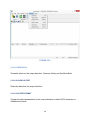
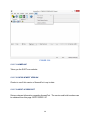
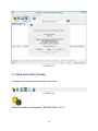
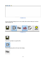
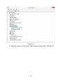
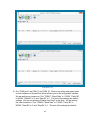
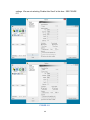
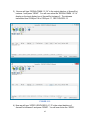
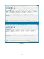
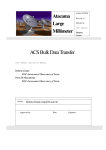
SUDT AccessPortTM Advanced
Terminal / Monitor / Debugger
Version 1.37 User Manual
Version 1.0 - January 20, 2015
CHANGE HISTORY
Version
1.0
Date
January 20, 2015
Description of Changes
Initial Publication of Document
COPYRIGHT NOTICE
AccessPortTM is authored and copyright protected by SUDT Studio. Jeddy Ventures
Limited Liability Company has obtained written permission to distribute AccessPortTM ,
freeware software. This manual is copyright protected by Jeddy Ventures Limited
Liability Company. All rights are reserved by Jeddy Ventures Limited Liability Company.
No company or individual is authorized to duplicate or translate this manual in any form
without the written permission of Jeddy Ventures Limited Liability Company.
TRADEMARK NOTICE
SerialCommTM and its logo are registered trademarks of Jeddy Ventures Limited
Liability Company. AccessPortTM and its logo are registered trademarks of SUDT
Studio. Other trademarks used in this manual belong to their corresponding companies.
Usage of these trademarks is not permitted without written authorization from their
respective companies.
DISCLAIMER
Jeddy Ventures Limited Liability Company reserves the right to change the manual
entirely or in part with no advance notice. Due to the improvement of the software tool
and the version update of the software, modifications may be required. This manual is
only for your reference. Please contact us if you have any questions.
2
TABLE OF CONTENTS
1 SCOPE......................................................................................................................... 4
2 OVERVIEW .................................................................................................................. 4
3 FEATURES .................................................................................................................. 4
4 INSTALLATION OF THE ACCESSPORT SOFTWARE .............................................. 5
5 ACCESSPORT USER INTERFACE ............................................................................ 7
5.1 TERMINAL MODE .................................................................................................... 9
5.1.1 UPPER COM PORT STATUS BAR ............................................................................................................ 11
5.1.2 UPPER MENU BAR ....................................................................................................................................... 12
5.1.2.1 FILE CATEGORY ................................................................................................................................... 12
5.1.2.2 EDIT CATEGORY ................................................................................................................................... 14
5.1.2.3 VIEW CATEGORY .................................................................................................................................. 15
5.1.2.4 MONITOR CATEGORY ......................................................................................................................... 17
5.1.2.5 TOOLS CATEGORY .............................................................................................................................. 18
5.1.2.6 OPERATION CATEGORY .................................................................................................................... 27
5.1.2.7 HELP CATEGORY ................................................................................................................................. 29
5.1.3 MAIN FUNCTIONS TOOLBAR .................................................................................................................... 31
5.1.4 INPUT DISPLAY BOX AND INPUT DATA CONTROL TOOLBAR ....................................................... 32
5.1.5 OUTPUT DATA BOX & OUTPUT DATA CONTROL TOOLBAR .......................................................... 34
5.1.6 BOTTOM STATUS BAR ............................................................................................................................... 34
5.2 MONITOR MODE.................................................................................................... 35
6 APPLICATION EXAMPLES ...................................................................................... 35
6.1 APPLICATION 1 – SINGLE SERIAL PORT LOOPBACK ..................................... 35
6.2 APPLICATION 2 – SERIAL DATA COMMUNICATION ......................................... 42
3
1 SCOPE
This user manual describes the AccessPortTM Advanced Serial Port Terminal / Monitor /
Debugger Freeware (AccessPort) authored by SUDT Studio to the extent of optional
operation with SerialCommTM products. AccessPort is rich with serial debugging
functions and not all of its functions will be covered in this manual. The AccessPort is a
Microsoft Windows-based serial debugging tool used in conjunction with the hosted
PC/laptop COM serial ports. This document describes the latest version of the
AccessPort: Version V1.37. The examples used in this document will be presented
using the Microsoft Windows 8 operating system.
2 OVERVIEW
AccessPort is an advanced serial terminal, monitor, simulation and data analysis tool
that can be used to configure and control serial devices as well as log, view, analyze, or
automate serial communication. SerialCommTM offers a number of data conversion
products; primarily RS232 to RS485/RS422/TTL/Ethernet/Fiber Optic converters for
your data conversion needs. AccessPortTM Advanced Serial Port Debugger Freeware is
an optional robust serial terminal/monitor software. It has a simple user interface that
can be used to control, monitor, test, and debug RS232/RS485/RS422/TTL/Ethernet/
Fiber Optic data utilizing our serial products for serial data conversion. Although
AccessPort is an advanced serial port terminal / monitoring tool with robust functionality
while easy to use due to its simplistic user interface. It is used by technicians,
engineers, software developers, as well as novices for designing or debugging serial
port-related projects.
AccessPort is a thoroughly tested, mature, and highly-stable product used worldwide by
professional engineers, technicians and software developers. It is used as a
development aid and debugging tool for RS232 / serial port related projects. Since it’s
so easy to use with a “simple” user interface, this tool is a favorite amongst serial port
novices.
The software supports Microsoft Windows 98, 2000, XP, Vista, Server 2003, 2008,
2013, Windows 7 32 bit and 64 bit and Windows 8 32 bit and 64 bit.
3 FEATURES
FEATURES LIST
4
1) Terminal / Monitor / Debugging Modes
2) Freeware Program that is mature, bug free and widely used in industry
3) Simple user interface with robust features
4) In and out data streams logging
5) Multiple Software instance can run simultaneously
6) Communication ports status displaying
7) Support of different formats of data (ASCII, HEX) and different length words
8) Full Duplex
9) Auto Send Functionality
10) Transfers data from file
11) Different display modes
12) Full history of sending and receiving commands and data
13) Supported baud rates range: 110..256,000 bps, and support custom baud rate
14) Can work with COM ports of the following types:
a. Standard on-board ports
b. Extension board ports
c. COM ports connected to computer through USB port with virtual ports
15) Can save current session including data sent and received
4 INSTALLATION OF THE ACCESSPORT SOFTWARE
The AccessPort Software should be installed on the host Windows based PC or laptop
that has access to the serial port that will be controlled or monitored. The installation
procedure is as follows:
1) Make sure AccessPort is compatible with your operating system. The software
supports Microsoft Windows 98, 2000, XP, Vista, Server 2003, 2008, 2013,
Windows 7 32 bit and 64 bit and Windows 8 32 bit and 64 bit.
2) Download the AccessPort software; the zip file may be downloaded from our
www.serialcomm.com website or www.sudt.com website. The download is
available in our DOWNLOADS section of our top menu throughout our website.
3) Extract the files using WINZIP or similar .zip extraction program. An AccessPort
directory structure will be created with an AccessPort .exe executable file. SEE
FIGURE 4.1
5
FIGURE 4.1
4) The AccessPort software does not install into the computer but uses an
executable file AccessPort.exe to initiate the program. This adds flexibility and
allows for running of multiple instances of the program. Open Windows Explorer
and go to the location where AccessPort is hosted and click on the
AccessPort.exe to run the program. SEE FIGURE 4.2
6
FIGURE 4.2
5 ACCESSPORT USER INTERFACE
The AccessPort Software Interface has many advanced features yet simple to use. It
has two main functions 1) Terminal Mode and 2) Monitor Mode. By selecting the
Terminal tab the following screen will appear. SEE FIGURE 5.1
7
FIGURE 5.1
By selecting the Monitor tab the following screen will appear. SEE FIGURE 5.2
8
FIGURE 5.2
5.1 TERMINAL MODE
We will be documenting the Terminal Mode interface of AccessPort and not the Monitor
Mode interface for simplicity. We will be using the Terminal Mode to control, monitor,
debug, and test the associated serial ports and SerialComm conversion products
connected to the serial ports. SEE FIGURE 5.3
9
FIGURE 5.3
The Terminal Mode Interface if divided into 6 operational sections:
1) Upper COM port status bar. SEE FIGURE 5.4
FIGURE 5.4
2) Upper menu bar. SEE FIGURE 5.5
FIGURE 5.5
3) Main functions toolbar. SEE FIGURE 5.6
FIGURE 5.6
10
4) Input display box and control toolbar. SEE FIGURE 5.7
FIGURE 5.7
5) Output data box and control and status toolbar. SEE FIGURE 5.8
FIGURE 5.8
6) Bottom status bar. SEE FIGURE 5.9
FIGURE 5.9
5.1.1 UPPER COM PORT STATUS BAR
This status bar shows which COM port is used and the selected attributes. This status
bar will also tell you whether the port is opened or closed. SEE FIGURE 5.10
FIGURE 5.10
11
5.1.2 UPPER MENU BAR
The upper menu bar is a horizontal menu of main functions available on AccessPort.
There are six main categories: “File”, “Edit”, “View”, “Monitor”, “Tools”, “Operation”, and
“Help”. SEE FIGURE 5.11
FIGURE 5.11
5.1.2.1 FILE CATEGORY
The “File” Category saves data and settings to a file, exports data and exits the
program. The “File” Category has the “Save”, “Save As”, “Export As HexDump”,and
“Exit” options. SEE FIGURE 5.12
FIGURE 5.12
12
5.1.2.1.1 SAVE
Saves the AccessPort data and settings.
5.1.2.1.2 SAVE AS
Saves the AccessPort data and settings to a specified file name.
5.1.2.1.3 EXPORT AS HEXDUMP
The data from AccessPort can be exported to a file in Hexadecimal format. Specify the
start location and stop location. There are some other parameters you can choose.
The Hexadecimal formatted data can be exported to the clipboard or a file by choosing
the appropriate option. SEE FIGURE 5.13
FIGURE 5.13
13
5.1.2.1.4 EXIT
Exits the AccessPort program.
5.1.2.2 EDIT CATEGORY
The “Edit” Category can undo a function, cut, paste and delete and select data in the
output display box. The “Edit” Category has the “Undo”, “Cut”, “Copy”, “Paste”, “Delete”,
and “Select All” options. SEE FIGURE 5.14
FIGURE 5.14
5.1.2.2.1 UNDO
Undo a previous function.
14
5.1.2.2.2 CUT
Cuts input display data.
5.1.2.2.3 COPY
Copies input display data.
5.1.2.2.4 PASTE
Pastes input display data.
5.1.2.2.5 DELETE
Deletes input display data.
5.1.2.2.6 SELECT ALL
Selects all of the input display data.
5.1.2.3 VIEW CATEGORY
These options control viewing of AccessPort. It allows for the selecting of unselecting
view sections of AccessPort for display. SEE FIGURE 5.15
15
FIGURE 5.15
5.1.2.3.1 TOOLBAR
Turns on and off the Icons toolbar.
5.1.2.3.2 STATUS BAR
Turns on and off the bottom status bar.
5.1.2.3.3 SENDING BAR
Turns on and off the output data box section.
5.1.2.3.4 DISPLAY BAR
16
Turns on and off the input display box section.
5.1.2.3.5 LANGUAGE
Changes the language of AccessPort. The available options are English, Chinese
(Simplified), Chinese (Traditional), and Russian.
5.1.2.4 MONITOR CATEGORY
The “Monitor” category has functions to control the Monitor mode. The “Monitor”
category has the “Clear All”, “Auto Scroll”, “Show Hex”, “Capture Events”, “Start
Monitor”, “Stop Monitor”, and “Ports” options. SEE FIGURE 5.16
FIGURE 5.16
5.1.2.4.1 CLEAR ALL
17
Clears all data.
5.1.2.4.2 AUTO SCROLL
Turns on or off the Auto Scroll function.
5.1.2.4.3 SHOW HEX
Turns on or off the display of HEX (Hexadecimal).
5.1.2.4.4 CAPTURE EVENTS
Turns on or off the ability to captures events.
5.1.2.4.5 START MONITOR
Starts the monitor.
5.1.2.4.6 STOPS MONITOR
Stops the monitor.
5.1.2.4.7 PORTS
Selects the ports to monitor.
5.1.2.5 TOOLS CATEGORY
The “Tools” category is a collection of some useful software tools. The “Tools” category
has the “Port Switch”, “Transfer File”, “Configuration”, “Start Debug”, “Select Font”, and
“Background Color” menu options. SEE FIGURE 5.17
18
FIGURE 5.17
5.1.2.5.1 PORT SWITCH
Switches ports and toggles the “Comm” status on the bottom of the display.
5.1.2.5.2 TRANSFER FILE
Transfers a file. Select the file you want to transfer and press the “SEND” button SEE
FIGURE 5.18
19
FIGURE 5.18
5.1.2.5.3 CONFIGURATION
Configures the COM port and serial settings. There is a collection of six menu screens:
“General”, “Event Control”, “Flow Control”, Timeout Control” and “Monitor Control” The
default view is the “General” configuration menu option. SEE FIGURE 5.19
5.1.2.5.3.1 GENERAL
The “General” configuration menu option contains the main serial port settings and
configuration. In order to operate AccessPort the COM port being used must be
configured and opened. Selecting the presented required settings and selecting “OK”
opens the COM port. The General settings are divided into six sections: “Custom Baud
Rate”, “Serial Port Settings”, “Send Display”, “Receive Display”, “AutoSend”, and
“Advanced”. SEE FIGURE 5.19
5.1.2.5.3.1.1 CUSTOM BAUD RATE
20
The “Custom Baud Rate” selects the baud rate data is being transmitted and received.
The baud rate is the speed in which the data is be transmitted. The supported baud
rates range from 110 bps to 256,000 bps. Standard baud rates are available from the
dropdown menu in the Serial Port Settings section. Custom baud rates can be also
entered by checking the “Enable” option and typing the custom baud rate. SEE
FIGURE 5.19
5.1.2.5.3.1.2 SERIAL PORT SETTINGS
The “Serial Port Settings” allow the COM Port, Baud Rate, Parity Bit, Data Bit, and Stop
Bit to be configured. SEE FIGURE 5.19
5.1.2.5.3.1.3 SEND DISPLAY
The “Send Display” selects either Char Format (ASCII Character) or Hex Format
(Hexadecimal Number) for the output data that will be sent. SEE FIGURE 5.19
5.1.2.5.3.1.4 RECEIVE DISPLAY
The “Received Display” selects either Char Format (ASCII Character) or Hex Format
(Hexadecimal Number) for the input data display that will be received. SEE FIGURE
5.19
5.1.2.5.3.1.5 AUTOSEND
The “AutoSend” allows the output data to be continuously transmitted with a delay in ms
at the end of each transmit specified by the Cycle value. To enable “AutoSend” check
the Enable AutoSend box. SEE FIGURE 5.19
5.1.2.5.3.1.6 ADVANCED
The “Advanced” can automatically open a port as soon as the application starts, or
notify of any available updates. SEE FIGURE 5.19
21
FIGURE 5.19
5.1.2.5.3.2 EVENT CONTROL
“Event Control” sets trigger events, if required. Check the “Event Control Settings”
options you want to trigger an event. SEE FIGURE 5.20
22
FIGURE 5.20
5.1.2.5.3.3 FLOW CONTROL
The “Flow Control” settings can be used if flow control is necessary. Flow control is not
used by default. You can select whether NONE, RTS/CTS (Hardware), DTR/DSR
(Hardware), or XOFF/XON (Software) flow control will be used. Hardware and Software
Flow control settings can be configured with the “Hardware Control Settings” or
“Software Control Settings”. SEE FIGURE 5.21
23
FIGURE 5.21
5.1.2.5.3.4 TIMEOUT CONTROL
Input and Output timeout control settings are configured here using the “Read Timeout”
settings and “Write Timeout” settings. SEE FIGURE 5.22
24
FIGURE 5.22
5.1.2.5.3.5 MONITOR CONTROL
The “Monitor” settings allow the maximum data buffer to be defined. SEE FIGURE 5.23
25
FIGURE 5.23
5.1.2.5.4 START DEBUG
This is an advanced feature that will not be covered in the document. The dropdown
looks like this. SEE FIGURE 5.24
26
FIGURE 5.24
5.1.2.5.5 SELECT FONT
Changes the font, text attributes and color of the input display data.
5.1.2.5.6 BACKGROUND COLOR
Changes the background color of the input display box.
5.1.2.6 OPERATION CATEGORY
The “Operation” category is a collection of operational functions. The “Operation”
category has the “Send Data”, “Clear Output”, “Output Format”, “Reset Counter”, “Clear
Input”, and “Display Format” menu options. SEE FIGURE 5.25
27
FIGURE 5.25
5.1.2.6.1 SEND DATA
Transmits data from the output data box. Same as clicking on Send/AutoSend.
5.1.2.6.2 CLEAR OUTPUT
Clears the data from the output data box.
5.1.2.6.3 OUTPUT FORMAT
Toggles the data representation of the output data box to either ASCII characters or
Hexadecimal format.
28
5.1.2.6.4 RESET COUNTER
The bottom status bar displays the TX count and RX count. These counts represent the
number of bytes transmitted and received. Reset Counter resets these counts to zero.
5.1.2.6.5 CLEAR INPUT
Clears the data input display box.
5.1.2.6.6 DISPLAY FORMAT
Toggles the data representation of the input display box to either ASCII characters or
Hexadecimal format.
5.1.2.7 HELP CATEGORY
The “Help” category is a collection of help related operations. The “Help” category has
the “Homepage”, “Check Newest Version”, and “About AccessPort” menu options. SEE
FIGURE 5.26
29
FIGURE 5.26
5.1.2.7.1 HOMEPAGE
Takes you the SUDT.com website.
5.1.2.7.2 CHECK NEWEST VERSION
Checks to see if this version of AccessPort is up-to-date.
5.1.2.7.3 ABOUT ACCESSPORT
Returns relevant information regarding AccessPort. The version and build numbers can
be obtained from this page. SEE FIGURE 5.27
30
FIGURE 5.27
5.1.3 MAIN FUNCTIONS TOOLBAR
The graphic icon toolbar provides main function icons.
FIGURE 5.28
Initiates the serial port configuration. SEE SECTION 5.1.2.5.3
31
Switches ports. SEE SECTION 5.1.2.5.1
Transfers a file. SEE SECTION 5.1.2.5.2
Shows predefined data lists as well as echoes transmitted data to the input data box.
Resets the TX and RX counters. SEE SECTION 5.1.2.6.4
Displays “About SUDT AccessPort” screen. SEE SECTION 5.2.7.3
5.1.4 INPUT DISPLAY BOX AND INPUT DATA CONTROL TOOLBAR
The input display box is where the data that is received by AccessPort is displayed.
SEE FIGURE 5.29
32
FIGURE 5.29
On top of the input display box is an icon toolbar with common data input functions.
SEE FIGURE 5.30
FIGURE 5.30
Saves the input data to a specified file.
Pauses displaying data on the input data display.
33
Changes the input data display format to Hex (Hexadecimal).
Changes the input data display format to Char (ASCII Character).
Clears the input data display
Adds carriage returns/line feeds to the input data display.
5.1.5 OUTPUT DATA BOX & OUTPUT DATA CONTROL TOOLBAR
The output input box is where the data to be transmitted is typed in. The toolbar on top
allows you to input data in Hex or Char format, plain text or hex string format and in real
time or not. The toolbar also has the SEND / AUTOSEND button. SEE FIGURE 5.31
FIGURE 5.31
5.1.6 BOTTOM STATUS BAR
34
The bottom status bar shows the handshaking and flow control indicators of the comm
status. It also show the TX (transmit) and RX (receive) data counts and serial port
settings. SEE FIGURE 5.32
FIGURE 5.32
5.2 MONITOR MODE
The Monitor mode interface will not be covered in this document.
6 APPLICATION EXAMPLES
Two application examples will be presented demonstrating how AccessPort can be
used to test our products. The first application is a simple loopback test of a single
serial port or serial device. The second application demonstrates the data
communication between two serial ports or serial devices. In both examples the
terminal modes will be used.
6.1 APPLICATION 1 – SINGLE SERIAL PORT LOOPBACK
A single port or device loopback test is a very useful way of determining whether a
serial port, attached device, or converter is functioning properly. A loopback test can be
performed on a serial RS232 port or device by connecting TX and RX (pins 2 and 3)
together. A loopback test can only be performed on other full duplex (simultaneous
bidirectional serial devices) protocols. By using our RS232 to RS422 converter, a
loopback test on RS422 can be performed by connecting TX+ to RX+ and TX- to RX-.
In addition, our RS232 to TTL converters can be looped back by connecting TX to RX.
Our fiber optic converters can be looped back by connecting fiber in to fiber out. RS485
is half duplex and cannot be single converter loop back tested.
In this example we will be looping back our USB-232-2 USB to RS232 adapter by
connecting TX to RX (pin 2 to pin 3) on the DB9 connector. We are using a USB to
RS232 adapter because the computer we are using does not have a serial port. We will
only need to open one instance of AccessPort since the looped back data transmitted
35
will be received by the same port and be displayed in the output box of the same
AccessPort.
1)
2)
3)
4)
5)
Add the loopback wire to the USB-232-2 USB to RS232 adapter.
Connect the USB-232-2 adapter to the USB port of the PC or laptop.
You will hear a beep sound. This means that the adapter driver was installed.
A virtual COM port is automatically created.
Determine which COM port you are using. The ports list of the device manager of
control panel will show you the used COM ports. SEE FIGURE 6.1
CONTROL PANEL→HARDWARE AND SOUND→DEVICE MANAGER→PORTS
(COM & LPT)
FIGURE 6.1
6) Our “COM port” is COM 17. Click on the yellow and green gears which will take
you to the configuration screen. We are setting the “Port” to COM17, “Baud
Rate” to 9600, “Parity Bit” to NONE, “Data Bit” to 8, and “Stop Bit” to 1. The rest
of the settings are default settings. We are not selecting “Enable Auto Send” at
this time. SEE FIGURE 6.2
36
FIGURE 6.2
7) Now we will type “SERIALCOMM 12345” in the output data box and press
“SEND”. You will now notice the “SERIALCOMM 12345” display on the input
display box. The transmitted data was looped back. SEE FIGURE 6.3
37
FIGURE 6.3
8) Again select the yellow and green gears to enter the configuration screen. Now
we will send continuous data by enabling the “Enable auto send” and setting the
Cycle time at 1000 ms, which means it will delay 1000 ms before repeating the
data again”. SEE FIGURE 6.4
38
FIGURE 6.4
9) Notice the “Send” button will change to “AutoSend”. SEE FIGURE 6.5
39
FIGURE 6.5
10) Type “SERIALCOMM 12345” in the output data box and press the “StartSend”
button. You will notice that “SERIALCOMM 12345” is being repeated on the
input display box. The data will be continually be sent until the “StopSend”
button is pressed. SEE FIGURE 6.6
40
FIGURE 6.6
11) You can change the input display format from ASCII Characters to HEX format
by clicking on the Hex button on top of the input message box. SEE FIGURE 6.7
41
FIGURE 6.7
6.2 APPLICATION 2 – SERIAL DATA COMMUNICATION
A good way to test data communication through two ports or two converters is
performing a two converter loop back with two COM ports of the PC/laptop.
Transmitting data from one COM port to other COM port using our converters is a useful
test to determine whether the conversion protocol is functioning properly. A test can be
performed on two serial RS232 ports by using a null modem adapter/cable in between
the serial ports or using our converters as well. Data transfer between two RS485
converters can be performed to test half duplex RS485 with this test method. The same
type of test can be used to also test RS422, TTL, Fiber Optic, and Ethernet using our
RS232 converters. Some protocols are half duplex (transfer data in one direction a
time) while others are full duplex (transfer data in both directions at the same time).
In this example, we will be using two USB-232-2 USB to RS232 adapters and two CON422-PE9 RS232 to RS422 converters to communicate from one RS232 port to the
other. We are using the USB to RS232 adapters because my PC does not have serial
ports. SEE FIGURE 6.8
42
FIGURE 6.8
1) Connect one USB-232-2 DB9 connector to the CON-422-PE9 RS232 DB9
connector.
2) Connect the other USB-232-2 DB9 connector to the other CON-422-PE9 RS232
DB9 connector.
3) Connect the RS422 ports of both converters.
a. Connect TX+ of the 1st converter to RX+ of the 2nd converter.
b. Connect TX- of the 1st converter to RX- of the 2nd converter.
c. Connect RX+ of the 1st converter to TX+ of the 2nd converter.
d. Connect RX- of the 1st converter to TX- of the 2nd converter.
4) Connect both of the USB-232-2 adapters to two USB ports of the PC or laptop.
5) You will hear a beep sound for each adapter. This means that each adapter’s
driver was installed.
6) Virtual COM ports are automatically created.
7) Determine which COM ports you are using. The ports list of the device manager
of control panel will show you the used COM ports.
CONTROL PANEL→HARDWARE AND SOUND→DEVICE MANAGER→PORTS
(COM & LPT) - SEE FIGURE 6.9
43
FIGURE 6.9
1) Open two instances of AccessPort. One for each port used. SEE FIGURE 6.10
44
FIGURE 6.10
2) Our “COM ports” are COM 17 and COM 18. Click on the yellow and green gears
on both instances of AccessPort which will take you to the configuration screens.
We are setting one instance to “Port” COM17, “Baud Rate” to 115200, “Parity Bit”
to NONE, “Data Bit” to 8, and “Stop Bit” to 1. The rest of the settings are default
settings. We are not selecting “Enable Auto Send” at this time. We are setting
the other instance to “Port” COM18, “Baud Rate” to 115200, “Parity Bit” to
NONE, “Data Bit” to 8, and “Stop Bit” to 1. The rest of the settings are default
45
settings. We are not selecting “Enable Auto Send” at this time. SEE FIGURE
6.11
FIGURE 6.11
46
3) Now we will type “SERIALCOMM 1 2 3 4” in the output data box of AccessPort
instance 1 and press “SEND”. You will now notice the “SERIALCOMM 1 2 3 4”
display on the input display box of AccessPort instance 2. The data was
transmitted from COM port 18 to COM port 17. SEE FIGURE 6.12
FIGURE 6.12
4) Now we will type “JEDDY VENTURES 5 6 7 8” in the output data box of
AccessPort instance 2 and press “SEND”. You will now notice the “JEDDY
47
VENTURES 5 6 7 8” display on the input display box of AccessPort instance 1.
Now the data was transmitted from COM port 17 to COM port 18. SEE FIGURE
6.13
FIGURE 6.13
5) Again select the yellow and green gears to enter the configuration screen for
both AccessPort instances. Now we will send continuous data by enabling the
48
“Enable auto send” and setting the Cycle time at 1000 ms which means it will
delay 1000 ms before repeating the data again”. SEE FIGURE 6.14
FIGURE 6.14
49
6) Type “SERIALCOMM 1 2 3 4” in the output data box of AccessPort 1 and press
the “StartSend” button. You will notice that “SERIALCOMM 1 2 3 4” is being
repeated on the input display box of AccessPort 2. The data will be continually
sent until the “StopSend” button is pressed. SEE FIGURE 6.15
FIGURE 6.15
50
7) Type “JEDDY VENTURES 1 2 3 4” in the output data box of AccessPort instance
2 and press the “StartSend” button. You will notice that “JEDDY 1 2 3 4” is being
repeated on the input display box of AccessPort instance 1. The data will be
continually sent until the “StopSend” button is pressed. SEE FIGURE 6.16
FIGURE 6.16
51
8) Since Serial RS232 is full duplex, data can be transferred bidirectionally and
simultaneously. Type “SERIALCOMM 1 2 3 4” in the output data box of
AccessPort 1 and press the “StartSend” button. You will notice that
“SERIALCOMM 1 2 3 4” is being repeated on the input display box of AccessPort
2. The data will be continually sent until the “StopSend” button is pressed. Type
“JEDDY VENTURES 1 2 3 4” in the output data box of AccessPort instance 2
and press the “StartSend” button. You will notice that “JEDDY 1 2 3 4” is being
repeated on the input display box of AccessPort instance 1. The data will be
continually sent until the “StopSend” button is pressed. Now data is being
transferred in both directions at the same time. SEE FIGURE 6.17
52
FIGURE 6.17
53