1
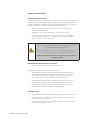
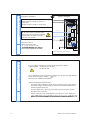
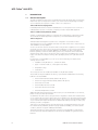
Instruction manual
MTL industrial security
September 2015
INM MTL Tofino 9202-ETS rev 1
MTL Tofino® 9202-ETS
Industrial security solution
Manuals and software are protected by copyright. All rights reserved. The copying,
reproduction, translation, conversion into any electronic medium or machine scannable form is
not permitted, either in whole or in part. An exception is the preparation of a backup copy of
the software for your own use. For devices with embedded software, the end-user license
agreement included in the management software installer package applies.
The performance features described here are binding only if they have been expressly agreed
when the contract was made. This document was produced by Measurement Technology
Limited. (MTL), according to the best of the company’s knowledge. MTL reserves the right
to change the contents of this document without prior notice. MTL can give no guarantee in
respect of the correctness or accuracy of the information in this document.
MTL can accept no responsibility for damages, resulting from the use of the network
components or the associated operating software. In addition, we refer to the conditions of
usespecified in the license contract.
You can get the latest version of this manual on the Internet at:www.mtl-inst.com
ii
INM MTL Tofino 9202-ETS 180915
CONTENTS
DoC . . . . . . . . . .. . . . . . . . . . . . . . . . . . . . . . . . . . . . . . . . . . . . . . . . . . . . . . . . . . . . . . . . . . . . . . . . . . . . v- vi
Safety instructions . . . . . . . . . . . . . . . . . . . . . . . . . . . . . . . . . . . . . . . . . . . . . . . . . . . . . . . . . . . . . . . . . 1-10
About this manual . . . . . . . . . . . . . . . . . . . . . . . . . . . . . . . . . . . . . . . . . . . . . . . . . . . . . . . . . . . . . . . . . . 11
1
DESCRIPTION. . . . . . . . . . . . . . . . . . . . . . . . . . . . . . . . . . . . . . . . . . . . . . . . . . . . . . . . . . . . . . . . . . . . . 12
1.1
General description . . . . . . . . . . . . . . . . . . . . . . . . . . . . . . . . . . . . . . . . . . . . . . . . . . . . . . . . . . . . . . . . . . . . . . . 12
1.2
Device View. . . . . . . . . . . . . . . . . . . . . . . . . . . . . . . . . . . . . . . . . . . . . . . . . . . . . . . . . . . . . . . . . . . . . . . . . . . . . . 14
1.3
Power Supply. . . . . . . . . . . . . . . . . . . . . . . . . . . . . . . . . . . . . . . . . . . . . . . . . . . . . . . . . . . . . . . . . . . . . . . . . . . . 15
1.4
Ethernet ports. . . . . . . . . . . . . . . . . . . . . . . . . . . . . . . . . . . . . . . . . . . . . . . . . . . . . . . . . . . . . . . . . . . . . . . . . . . . 15
1.4.1
10/100 Mbit/s twisted pair port. . . . . . . . . . . . . . . . . . . . . . . . . . . . . . . . . . . . . . . . . . . . . . . . . . . . . . . . . . . . 15
1.4.2
100 Mbit/s F/O port . . . . . . . . . . . . . . . . . . . . . . . . . . . . . . . . . . . . . . . . . . . . . . . . . . . . . . . . . . . . . . . . . . . . . 15
1.5
Display elements . . . . . . . . . . . . . . . . . . . . . . . . . . . . . . . . . . . . . . . . . . . . . . . . . . . . . . . . . . . . . . . . . . . . . . . . . 16
1.5.1
Device state. . . . . . . . . . . . . . . . . . . . . . . . . . . . . . . . . . . . . . . . . . . . . . . . . . . . . . . . . . . . . . . . . . . . . . . . . . . 16
1.6
Controls. . . . . . . . . . . . . . . . . . . . . . . . . . . . . . . . . . . . . . . . . . . . . . . . . . . . . . . . . . . . . . . . . . . . . . . . . . . . . . . . . 17
1.7
Management interfaces. . . . . . . . . . . . . . . . . . . . . . . . . . . . . . . . . . . . . . . . . . . . . . . . . . . . . . . . . . . . . . . . . . . . 17
1.7.1
1.7.2
1.8
V.24 interface. . . . . . . . . . . . . . . . . . . . . . . . . . . . . . . . . . . . . . . . . . . . . . . . . . . . . . . . . . . . . . . . . . . . . . . . . . 17
USB interface. . . . . . . . . . . . . . . . . . . . . . . . . . . . . . . . . . . . . . . . . . . . . . . . . . . . . . . . . . . . . . . . . . . . . . . . . . 17
Input/output interfaces. . . . . . . . . . . . . . . . . . . . . . . . . . . . . . . . . . . . . . . . . . . . . . . . . . . . . . . . . . . . . . . . . . . . 18
1.8.1
Signal contact (Digital output). . . . . . . . . . . . . . . . . . . . . . . . . . . . . . . . . . . . . . . . . . . . . . . . . . . . . . . . . . . . 18
1.8.2
Digital input. . . . . . . . . . . . . . . . . . . . . . . . . . . . . . . . . . . . . . . . . . . . . . . . . . . . . . . . . . . . . . . . . . . . . . . . . . . 18
2
INSTALLATION. . . . . . . . . . . . . . . . . . . . . . . . . . . . . . . . . . . . . . . . . . . . . . . . . . . . . . . . . . . . . . . . . . . . 19
2.1
Overview. . . . . . . . . . . . . . . . . . . . . . . . . . . . . . . . . . . . . . . . . . . . . . . . . . . . . . . . . . . . . . . . . . . . . . . . . . . . . . . . 19
2.2
Checking the package contents . . . . . . . . . . . . . . . . . . . . . . . . . . . . . . . . . . . . . . . . . . . . . . . . . . . . . . . . . . . . . 19
2.3
Installing and grounding the device. . . . . . . . . . . . . . . . . . . . . . . . . . . . . . . . . . . . . . . . . . . . . . . . . . . . . . . . . .19
2.3.1
Installing the device onto the DIN rail. . . . . . . . . . . . . . . . . . . . . . . . . . . . . . . . . . . . . . . . . . . . . . . . . . . . . . 19
2.3.2
Mounting on a vertical flat surface. . . . . . . . . . . . . . . . . . . . . . . . . . . . . . . . . . . . . . . . . . . . . . . . . . . . . . . . 20
2.3.3
Grounding the device. . . . . . . . . . . . . . . . . . . . . . . . . . . . . . . . . . . . . . . . . . . . . . . . . . . . . . . . . . . . . . . . . . . 21
2.4
Connecting the terminal blocks . . . . . . . . . . . . . . . . . . . . . . . . . . . . . . . . . . . . . . . . . . . . . . . . . . . . . . . . . . . . . 21
2.4.1
2.4.2
Connecting the power supply and signal lines . . . . . . . . . . . . . . . . . . . . . . . . . . . . . . . . . . . . . . . . . . . . . . 21
Wiring the digital input (optional). . . . . . . . . . . . . . . . . . . . . . . . . . . . . . . . . . . . . . . . . . . . . . . . . . . . . . . . . 22
2.5
Operating the device. . . . . . . . . . . . . . . . . . . . . . . . . . . . . . . . . . . . . . . . . . . . . . . . . . . . . . . . . . . . . . . . . . . . . . 23
2.6
Connecting data cables. . . . . . . . . . . . . . . . . . . . . . . . . . . . . . . . . . . . . . . . . . . . . . . . . . . . . . . . . . . . . . . . . . . . 23
3
CONFIGURATION . . . . . . . . . . . . . . . . . . . . . . . . . . . . . . . . . . . . . . . . . . . . . . . . . . . . . . . . . . . . . . . . . 24
3.1
Making basic settings . . . . . . . . . . . . . . . . . . . . . . . . . . . . . . . . . . . . . . . . . . . . . . . . . . . . . . . . . . . . . . . . . . . . . 24
3.1.1
USB interface. . . . . . . . . . . . . . . . . . . . . . . . . . . . . . . . . . . . . . . . . . . . . . . . . . . . . . . . . . . . . . . . . . . . . . . . . . 25
3.2
Fault LED. . . . . . . . . . . . . . . . . . . . . . . . . . . . . . . . . . . . . . . . . . . . . . . . . . . . . . . . . . . . . . . . . . . . . . . . . . . . . . . . 26
3.3
Operating Modes. . . . . . . . . . . . . . . . . . . . . . . . . . . . . . . . . . . . . . . . . . . . . . . . . . . . . . . . . . . . . . . . . . . . . . . . . 27
4
MAINTENANCE AND SERVICE. . . . . . . . . . . . . . . . . . . . . . . . . . . . . . . . . . . . . . . . . . . . . . . . . . . . . . . 28
5
DISASSEMBLY . . . . . . . . . . . . . . . . . . . . . . . . . . . . . . . . . . . . . . . . . . . . . . . . . . . . . . . . . . . . . . . . . . . . 29
6
TECHNICAL DATA . . . . . . . . . . . . . . . . . . . . . . . . . . . . . . . . . . . . . . . . . . . . . . . . . . . . . . . . . . . . . . . . . 30
6.1
General technical data. . . . . . . . . . . . . . . . . . . . . . . . . . . . . . . . . . . . . . . . . . . . . . . . . . . . . . . . . . . . . . . . . . . . . 30
6.2
Digital Input . . . . . . . . . . . . . . . . . . . . . . . . . . . . . . . . . . . . . . . . . . . . . . . . . . . . . . . . . . . . . . . . . . . . . . . . . . . . . 31
6.3
Dimension drawings . . . . . . . . . . . . . . . . . . . . . . . . . . . . . . . . . . . . . . . . . . . . . . . . . . . . . . . . . . . . . . . . . . . . . . 31
6.4
EMC and immunity . . . . . . . . . . . . . . . . . . . . . . . . . . . . . . . . . . . . . . . . . . . . . . . . . . . . . . . . . . . . . . . . . . . . . . . 32
6.5
Nertwork range. . . . . . . . . . . . . . . . . . . . . . . . . . . . . . . . . . . . . . . . . . . . . . . . . . . . . . . . . . . . . . . . . . . . . . . . . . . 33
6.6
Power consumption/power output . . . . . . . . . . . . . . . . . . . . . . . . . . . . . . . . . . . . . . . . . . . . . . . . . . . . . . . . . . 33
6.7
Scope of delivery . . . . . . . . . . . . . . . . . . . . . . . . . . . . . . . . . . . . . . . . . . . . . . . . . . . . . . . . . . . . . . . . . . . . . . . . . 33
6.8
Accessories. . . . . . . . . . . . . . . . . . . . . . . . . . . . . . . . . . . . . . . . . . . . . . . . . . . . . . . . . . . . . . . . . . . . . . . . . . . . . . 33
6.9
Underlying technical standards . . . . . . . . . . . . . . . . . . . . . . . . . . . . . . . . . . . . . . . . . . . . . . . . . . . . . . . . . . . . . 34
INM MTL Tofino 9202-ETS 180915
iii
iv
INM MTL Tofino 9202-ETS 180915
INM MTL Tofino 9202-ETS 180915
v
vi
INM MTL Tofino 9202-ETS 180915
SAFETY INSTRUCTIONS
General safety instructions
You operate this device with electricity. Improper usage of the device entails the risk
of physical injury or significant property damage. The proper and safe operation of
this device depends on proper handling during transportation, proper storage and
installation, and careful operation and maintenance procedures.
• Before connecting any cable, read this document, and the safety
instructions and warnings.
• Operate the device with undamaged components exclusively.
• The device is free of any service components. In case of a damaged
or malfunctioning the device, turn off the supply voltage and return the
device to back to us for inspection.
UNCONTROLLED MACHINE ACTIONS
To avoid uncontrolled machine actions caused by data loss, configure all
the data transmission devices individually.
Before you start any machine which is controlled via data transmission, be
sure to complete the configuration of all data transmission devices.
Failure to follow these instructions can result in death, serious injury,
or equipment damage.
Qualification requirements for personnel
• Only allow qualified personnel to work on the device.
Qualified personnel have the following characteristics:
•
Qualified personnel are properly trained. Training as well as practical
knowledge and experience make up their qualifications. This is the
prerequisite for grounding and labeling circuits, devices, and systems
in accordance with current standards in safety technology.
• Qualified personnel are aware of the dangers that exist in their work.
• Qualified personnel are familiar with appropriate measures against
these hazards in order to reduce the risk for themselves and others.
• Qualified personnel receive training on a regular basis.
Intended usage
• Use the product only for the application cases described in this manual.
• Operate the product only according to the technical specifications. See “Technical data” on page 30.
• Connect to the product only components suitable for the requirements
of the specific application case.
INM MTL Tofino 9202-ETS 180915
1
National and international safety regulations
Verify that the electrical installation meets local or nationally applicable
safety regulations.
Grounding the device
Grounding the device is by means of a separate ground connection on
the device.
• Ground the device before connecting any other cables.
• Disconnect the grounding only after disconnecting all other cables.
The overall shield of a connected shielded twisted pair cable is connected to the
ground connector on the front panel as a conductor.
Supply voltage
The supply voltage is electrically isolated from the housing.
Connect only a supply voltage that corresponds to the type plate of your device.
Every time you connect the electrical conductors, make sure that the following
requirements are met:
• The power supply conforms to overvoltage category I or II.
•
The power supply has an easily accessible disconnecting device
(e.g., a switch or a plug). This disconnecting device is clearly identified.
So in the case of an emergency, it is clear which disconnecting device belongs to which power supply cable.
• The electrical wires are voltage-free.
• The power supply is Class 2 compliant.
• The supply voltage inputs are designed for operation with safety
extra-low voltage. Connect only SELV circuits with voltage restrictions
in line with IEC/EN 60950-1 to the supply voltage connections.
• Supply with AC voltage:
A fuse is located in the outer conductor of the power supply.
The neutral conductor is on ground potential. Otherwise, a fuse is
also located in the neutral conductor.
Regarding the properties of this fuse: See “General technical data”
on page 30.
• Supply with DC voltage:
A fuse suitable for DC voltage is located in the plus conductor of the
power supply.
The minus conductor is on ground potential. Otherwise, a fuse is also
located in the minus conductor.
Regarding the properties of this fuse: See “General technical data”
on page 30.
• The wire diameter of the power supply cable is at least 0.5mm²
(AWG20) on the supply voltage input.
2
INM MTL Tofino 9202-ETS 180915
• The cross-section of the protective conductor is the same size as
or bigger than the cross-section of the power supply cables.
• The power supply cables used are permitted for the temperature
range required by the application case.
• Relevant for North America:
Use 60/75 or 75 °C copper (Cu) wire only.
Internal fuses are triggered only in the case of a detected error in the device. In
case of damage or malfunction of the device, turn off the supply voltage and return
the device to the plant for inspection.
Input/output interfaces
Every time you connect the electrical conductors, make sure that the following
requirements are met:
• The electrical wires are voltage-free.
•
The connected voltage is limited by a current limitation device or a fuse.
Observe the electrical threshold values for the signal contact.
See “General technical data” on page 30.
Observe the electrical threshold values for the digital input.
See “Digital input” on page 31.
Installation site requirements
• Verify that there is at least 4 in (10 cm) of space above and below
the device.
• Verify that there is at least 0.8 in (2 cm) of space on the right and left sides
of the device.
• Install the device in a fire protected enclosure according to EN 60950-1.
Housing
Only technicians authorized by the manufacturer are permitted to open the
housing.
• Never insert pointed objects (narrow screwdrivers, wires, etc.) into the
device or into the connection terminals for electric conductors. Do not
touch the connection terminals.
• Keep the ventilation slits free to ensure good air circulation.
• Install the device in the vertical position.
• At ambient temperatures > 140 °F (60 °C):
The surfaces of the device housing may become hot. Avoid touching
the device while it is operating.
LED or laser components
LED or LASER components according to IEC 60825-1 (2007):
CLASS 1 LASER PRODUCT
CLASS 1 LED PRODUCT Input/output interfaces
INM MTL Tofino 9202-ETS 180915
3
CE marking
The labeled devices comply with the regulations contained in the following
European directive(s):
2004/108/EC (EMC)
Directive of the European Parliament and the council for standardizing the
regulations of member states with regard to electromagnetic compatibility.
2011/65/EU (RoHS)
Directive of the European Parliament and of the Council on the restriction
of the use of certain hazardous substances in electrical and electronic
equipment.
In accordance with the above-named EU directive(s), the EU conformity declaration
will be at the disposal of the relevant authorities at the following address:
Measurement Technology Limited,
Great Marlings, Butterfield, Luton
Beds LU2 8DL
Tel: +44 (0)1582 723633 Fax: +44 (0)1582 422283
E-mail: [email protected]
The device can be used in the industrial sector.
• Interference immunity: EN 61000-6-2
• Emitted interference: EN 55022
You find more information on technical and industry standards here:
“Technical data” on page 30.
This is a class A device. This device can cause interference in living areas,
and in this case the operator may be required to take
appropriate measures.
NOTE:
The assembly guidelines provided in these instructions must be strictly adhered to in order to
observe the EMC threshold values.
Relevant for use in North America
Use this device solely in Class 2 Circuits.
continued overleaf
4
INM MTL Tofino 9202-ETS 180915
Relevant for use in Hazardous Locations
Suitable for use in Hazardous locations Class I Division 2, Groups A, B,
C, D and Class 1 Zone 2, IIC.
The relay connections are to be installed and used within their Entity Parameters
as per Control Drawing 000174247DNR – see the following drawings
Avertissement
Risque d’explosion - Ne pas débrancher tant que le circuit est sous
tension à moins que l’emplacement soit connu pour ne contenir
aucune concentration de gaz inflammable.
Avertissement
Risque d’explosion - La substitution de tout composant peut rendre
ce matériel incompatible pour une utilisation en classe I, division 2 /
zone 2.
INM MTL Tofino 9202-ETS 180915
5
Vmax
30 V
Imax
90 mA
Ci
3nF
MTL Tofino 9202-ETS
!
FAULT
NET 2
RESET
SAVE / LOAD
POWER
NET 1
MODE
Li
1 µH
USB pin 4
USB
1
USB pin 1
2
!
FAULT
+24V (P1)
MTL Tofino 9202-ETS
+24V (P2)
DI (+)
DI (-)
OV
OV
Document No.: 000174247DNR
CONTROL DRAWING - MTL Tofino 9202-ETS
for Use in Hazardous Locations
Class I Division 2, Groups A, B, C, D
Rev. 0 01-12-2014
FAULT contacts
THE RELAY TERMINALS ARE DEPENDENT UPON
THE FOLLOWING ENTITY
V24
Page 1/2
The earth conductor must be at least of the same wire size
(mm² or AWG) as the supply conductors.
Document No.: 000174247DNR
CONTROL DRAWING - MTL Tofino 9202-ETS
for Use in Hazardous Locations
Class I Division 2, Groups A, B, C, D
Rev. 0 01-12-2014
DIVISION 2 / ZONE 2.
i
Page 2/2
6
i
i
+L
L
L
i
INM MTL Tofino 9202-ETS 180915
FCC note
This device complies with part 15 of the FCC rules. Operation is subject to the following
two conditions: (1) this device may not cause harmful interference; (2) this device must
accept any interference received, including interference that may cause undesired
operation.
Appropriate testing has established that this device fulfills the requirements of a class A
digital device in line with part 15 of the FCC regulations.
These requirements are designed to provide sufficient protection against interference
when the device is being used in a business environment.
The device creates and uses high frequencies and can also radiate high frequencies,
and if it is not installed and used in accordance with this operating manual, it can cause
radio transmission interference. The use of this device in a living area can also cause
interference, and in this case the user is obliged to cover the costs of removing the
interference.
Recycling note
After usage, this device must be disposed of properly as electronic waste, in accordance
with the current disposal regulations of your county, state, and country.
Relevant for use in Ex Zone 2 according to ATEX 95
(European directive 94/9/EC)
In Ex Zone 2, only the devices with a corresponding label may be operated.
The devices are to be installed and used according to the to the European directive
94/9/EC. Details see the next page.
INM MTL Tofino 9202-ETS 180915
7
APPLICATIONS INVOLVING ZONE 2 HAZARDOUS AREAS
Important: see the Declaration of Conformity on page ii at the front of this manual
for important additional information regarding the use of these products in countries
governed by the ATEX Directive. The following information is in accordance with the
Essential Health and Safety Requirements (Annex II) of the EU Directive 94/9/EC [the
ATEX Directive – safety of apparatus] and is provided for those locations where the ATEX
Directive is applicable.
General
a) This equipment must only be installed, operated and maintained by competent personnel.
Such personnel shall have undergone training, which included instruction on the various types
of protection and installation practices, the relevant rules and regulations, and on the general
principles of area classification. Appropriate refresher training shall be undertaken on a regular
basis. [See clause 4.2 of EN 60079-17].
b) This equipment has been designed to provide protection against all the relevant additional
hazards referred to in Annex II of the directive, such as those in clause 1.2.7.
c) The 9202-ETS and associated products mentioned in the DoC are certified as meeting
the requirements of IEC/EN 60079-15 for Zone 2 applications and the European Community
permits Category 3G equipment, such as these items from the 9202-ETS range, to be installed
in Zone 2 flammable atmospheres provided it meets the requirements of the ATEX Directive.
Installation
a) The installation must comply with the appropriate European, national and local regulations,
which may include reference to the code of practice IEC/EN 60079-14. In addition, particular
industries or end users may have specific requirements relating to the safety of their installations
and these requirements should also be met. For the majority of installations the Directive
1999/92/EC [the ATEX Directive - safety of installations] is also applicable.
b) This apparatus may be installed in a safe area and also in a Zone 2 location providing that the
relevant installation conditions are met, as given in the Special Conditions here below:
Special conditions of Safe Use for Zone 2 applications
1) The modules shall be installed in a suitable enclosure in accordance with EN 60079-
15, taking into account the environmental conditions under which the requirement will be used.
2) Provisions shall be made to prevent the rated voltage from being exceeded by transient disturbance of more than 119V.
3) When the temperature under rated conditions exceeds 70°C at the cable or conduit entry point, or 80°C at the branching point of the conductors, the temperature specification of the selected cable shall be in compliance with the actual measured temperature values.
Inspection and maintenance
a) Inspection and maintenance should be carried out in accordance with European, national
and local regulations which may refer to the standard IEC/EN 60079-17. In addition specific
industries or end users may have specific requirements which should also be met.
b) Access to the internal circuitry must not be made during operation.
8
INM MTL Tofino 9202-ETS 180915
Repair
This product cannot be repaired by the user and must be replaced with an equivalent
certified product.
Marking
Each device is marked in compliance with the directive and relevant standards.
Equipment Name:
9202-ETS
ATEX Certificate No:
DEKRA 15ATEX0075X
Certification Code
II 3 G Ex nA IIC T4 Gc
INM MTL Tofino 9202-ETS 180915
9
CONTROL DRAWING - MTL Tofino 9202-ETS
according to the European Directive 94/9/EC
Ordinary Location, Non-Hazardous Area,
Nonexplosive Atmosphere
THE Fault Relays are tested as Sealed Device according to
ATEX EN 60079-15. Switching current max. 1 A,
Atex Zone 2
Explosive Atmosphere
MTL Tofino 9202-ETS
FAULT contacts
!
(resistive load)
Switching voltage max. 60 VDC or 30 VAC, SELV
The USB connector is for temporary connection
only. Do not use, connect, or disconnect unless
area is known to be non-hazardous. Connection
or disconnection in an explosive atmosphere
could result in an explosion.
FAULT
NET 2
RESET
SAVE / LOAD
POWER
NET 1
MODE
USB pin 4
USB
1
USB pin 1
2
!
Ambient Temperature rating:
Ta: 0 °C to +60 °C for “S“ types
-refer to the type designation on the device
( item 18 of product code: “Temperature range“)
FAULT
+24V (P1)
OV
OV
MTL Tofino 9202-ETS
Temperature Code: T4
+24V (P2)
DI (+)
DI (-)
V24
The earth conductor must be at least of the same wire size
(mm² or AWG) as the supply conductors.
CONTROL DRAWING - MTL Tofino 9202-ETS
according to the European Directive 94/9/EC
For Use in explosive atmospheres according to the European directive 94/9/EC:
Applied Standards: EN 60079-0, 2012 + A11 2013
EN 60079-15, 2010
The Use in Hazardous Locations with explosive atmospheres is only allowed for MTL 9202-ETS
which is labeled accordingly - including ”
II 3 G”,
”Ex nA IIC T4 Gc” “DEKRA
”DEKRA15ATEX0075X”.
13ATEX0184X”.
SPECIAL CONDITIONS FOR SAFE USE:
•
The modules shall be installed in a suitable enclosure providing a degree of protection of at
least IP54 according to EN 60529, taking into account the enviromental conditions under
which the equipment will be used.
•
Provisions shall be made to prevent the rated voltage from being exceeded by transient
disturbances of more than 119 V.
•
When the temperature under rated conditions exceeds 70°C at the cable or conduit entry
selected cable shall be in compliance with the actual measured temperature values.
10
INM MTL Tofino 9202-ETS 180915
About this manual
This manual contains a device description, safety instructions, a description
of the display, and the other information that you need to install the device.
The following manuals are available to registered users as PDF files from
https://www.mtl-inst.com
• Hardware Installation Manual
• Tofino Configurator User Manual
The Tofino Configurator software coordinates configuration, management, and
auditing of all Tofino Security Appliance devices from one workstation.
The software provides you with the following capabilities:
• Intuitive Windows-based graphical user interface
• Transfer of the configuration data from the application directly to the Tofino
Security Appliance devices in the field
• Simple verification of the configuration of Tofino Security Appliance
devices over the network
• Predefined templates for more than 125 IT and industrial
communication protocols
• Asset templates for quick and efficient creation of your plant’s assets
• Flexible security controls to tailor project access to meet your needs
GENERAL SAFETY INFORMATION
The following methods are used in this manual to alert the user to important information:-
WARNING !
Warnings are provided to ensure operator safety and MUST be followed.
CAUTION
Cautions are provided to prevent damage to the instrument.
NOTE
These are used to give general information to ensure correct operation.
INM MTL Tofino 9202-ETS 180915
11
MTL Tofino® 9202-ETS
1
1.1
DESCRIPTION
General description
The Tofino Industrial Security Solution is a distributed system that quickly and cost-effectively
implements cyber security protection within your control network. This package for helping
secure industrial control systems consists of three core components:
Tofino 9202-ETS Security Appliance
Industrially hardened devices that are installed between control system zones or in front of
individual and/or clusters of controllers, computers, and other ICS/SCADA equipment.
Tofino Loadable Security Modules (LSMs)
A variety of software plug-ins that let you customize the security features of each Tofino module.
These software modules help provide securityservices, such as Firewall and Event Logger.
Tofino Configurator
A Windows-based management system for the configuration of each Tofino module.
This manual focuses on the installation and setup of the first of these three components: the
Tofino 9202-ETS Security Appliance.
You can use the Tofino devices everywhere that security-sensitive equipment or zones require
a network connection. These devices can act as the link between control zones and networks
that have different security needs and capabilities. For example, an Tofino can be placed
between a primary control zone and a safety system zone, or between a PLC network and
an HMI network. Tofino devices can also be used to help protect vulnerable devices, such as
legacy controllers and computers running older operating systems, from cyber and network
events.
For each Tofino security appliance, you can choose from a wide range of variants when
ordering. These include:
•
Loadable Security Modules (i.e., software modules)
•
Types of network media (i.e., twisted pair versus fiber)
•
Temperature range
•Certifications
The security functions are installed as Loadable Security Modules (LSMs).
These LSMs can be pre-installed at the factory, or purchased and added later. The following
LSMs are currently available:
•
Tofino Firewall LSM (included by default in all options)
•
Tofino Event Logger LSM (included by default in all options)
•
Tofino NetConnect LSM
•
Tofino Modbus TCP Enforcer LSM
•
Tofino OPC Classic Enforcer LSM
•
Tofino EtherNet/IP Enforcer LSM
Additional LSMs are being developed continuously. If you need an LSM that is not in this list,
please contact your sales representative.
You administer the Tofino devices using the Tofino Configurator software. This software allows
you to configure all of your Tofino devices from one workstation. You can quickly create a model
of your entire control system by scanning IP ranges to discover Tofino devices already installed
on your network (this requires the NetConnect LSM). Visual editing tools help you create, edit,
and test your Tofino configuration.
Tofino devices are designed for the special requirements of industrial automation. They meet
the relevant industry standards, provide very high operational reliability, even under extreme
conditions, and offer long-term reliability and flexibility.
This product provides you with a large range of functions and industrially focused features,
which this and other manuals explain. These documents are available to registered users as
PDF files.
12
INM MTL Tofino 9202-ETS 180915
APPLICATION
CASE
CERTIFICATES
AND DECLARATIONS
CHARACTERISTIC VALUE
T9
TY
U9
UT
UY
UX
V9
VT
VU
VY
W9
WX
X9
Y9
STANDARD
APPLICATIONS
CE
X
X
X
X
X
X
X
X
X
X
X
X
X
X
X
EN 60950-1
X
X
X
X
X
X
X
X
X
X
X
X
X
X
X
EN 61131-2
X
X
X
X
X
X
X
X
X
X
X
X
X
X
X
FCC
X
X
X
X
X
X
UL 508
OIL AND GAS
APPLICATIONS
SUBSTATION
APPLICATIONS
RAILWAY
APPLICATIONS
(TRACKSIDE)
X
X
X
X
X
X
X
X
X
X
X
X
X
IEC 61850-3
X
ISA 12.12.01 –
CLASS I, DIV. 2
IEC 61850-3
X
X
X
X
X
X
X
X
X
X
X
X
IEEE1613
X
X
X
X
X
EN 50121-4
X
X
Z9
X
X
Table 1 - Assignment: application cases, certificates and declarations, characteristic values
LOADABLE
SECURITY
MODULES
(LSMS)
CHARACTERISTIC VALUE
0001
0003
0005
0007
0009
000B
000D
000F
000H
000K
000N
000Q
000S
000V
X
X
X
X
X
X
X
X
X
X
X
X
X
X
X
X
X
FIREWALL
(FW)a
NETCONNECT
(NC)
MODBUS TCP
ENFORCER
(MB)
OPC CLASSIC
ENFORCER
(OPC)
ETHERNET/IP
ENFORCER
(EIP)
X
X
X
X
X
X
X
X
X
X
X
X
X
X
X
X
X
X
X
X
000X
000Z
X
X
X
X
X
X
X
X
X
X
a - Includes Event Logger LSM
Table 2 - Combination options of the Tofino SA software modules
INM MTL Tofino 9202-ETS 180915
13
1.2
Device Overview
1a
6 pin, screwable terminal block for redundant supply voltage and signal contact
1b
Terminal block connection
2
LED display elements
3
6 pin, Ethernet port 1
alternatively, depending on
device variant
4
Tofino ID
5
Ethernet port 2 NET 2
alternatively, depending on
device variant
RJ45 socket for 10/100 Mbit/s twisted pair connections
DSC multimode socket for 100 Mbit/s F/O port
RJ45 socket for 10/100 Mbit/s twisted pair connections
DSC multimode socket for 100 Mbit/s F/O port
6
Grounding screw
7
Hole for mounting using a wall mounting plate
8
Locking gate for removing the device
9
V.24 interface
The V.24 interface is not active in this version of the firmware.
10a
2 pin, screwable terminal block for digital input
10b
Terminal block connection
11
USB interface
12
Save/Load/Reset button
Table 3 - Front view (using the example MTL Tofino 9202-ETS
14
INM MTL Tofino 9202-ETS 180915
1.3
Power Supply
A 6-pin, screwable terminal block is available for the redundant supply to the device.
For further information see “Supply voltage” on page 2.
1.4
Ethernet ports
1.4.1 10/100 Mbit/s twisted pair port
The 10/100 Mbit/s twisted pair port offers you the ability to connect network components
according to the IEEE 802.3 10BASE-T/100BASE-TX standard.
This port supports:
• Autocrossing (if autonegotiation is activated)
•Autonegotiation
•Autopolarity
• 10 Mbit/s half-duplex mode, 10 Mbit/s full duplex mode
• 100 Mbit/s half-duplex mode, 100 Mbit/s full duplex mode
Delivery state: autonegotiation active
The socket housing is electrically connected with the front panel.
The pin assignment corresponds to MDI-X.
1
2
3
4
5
6
7
8
Pin
Function
1
RD+
Recieve path
2
RD-
Recieve path
3
TD+
Recieve path
6
TD-
Recieve path
4, 5, 7, 8
—
Recieve path
Table 4 - Pin assignment of the 10/100 Mbit/ twisted pair port,
RJ-45 socket, MDI-X mode
1.4.2 100 Mbit/s F/O port
The 100 Mbit/s F/O port offers you the ability to connect network components according to
the IEEE 802.3 100BASE-FX standard.
This port supports:
• Full or half duplex mode
Default setting: Full duplex
INM MTL Tofino 9202-ETS 180915
15
1.5
Display elements
After the supply voltage is set up, the software starts and initializes itself.
Afterwards, the device performs a self-test.
POWER
FAULT
NET 1
NET 2
MODE
SAVE/
LOAD
RESET
1.5.1 Device state
These LEDs provide information about conditions which affect the operation of the
whole device.
LED
Display
Colour
Activity
Meaning
POWER
Supply voltage
—
None
Supply voltage is too low
NET 1
and
NET 2
FAULT
MODE
SAVE/
LOAD
System and USB
save/load errors
Network mode
Lights up
Supply voltage 1 or 2 is on
Lights up
Supply voltages 1 and 2 are on
—
None
Device detects an invalid or missing link
Green
Lights up
Device detects a valid link
Flashes 3 times
a period
Port is switched off
Yellow
Flashing
Device is transmitting and/or receiving data
Red
None
The signal contact is closed - it is not
reporting any detected errors.
Very short
flashing in
cycles of 0.5 s
A detected USB load or save error
occurred.
See table 8 on page 18.
None
The device is in Unconfigured mode.
Lights up
The device is in operational mode.
Green
Long flashing
The device is in test mode.
Preparation
Saving process
Green
Lights up (5 s)
The saving of the device diagnostic or log files to the
USB storage device is about to begin.
Preparation
Loading process
Yellow
Lights up (5 s)
The load of the configuration files from the USB storage
device is about to begin.
RESET
Preparation
Reset process
Yellow
Lights up (5 s)
The reset of the device to the factory defaults is about
to begin.
MODE
RESET
Execution
Saving process
Green
Flashing alternately
in left to right
sequence
The device saves the diagnostic files or log files on the
USB device.
Execution
Loading process
Yellow
Flashing alternately
in right to left
sequence
The device loads the configuration files from the USB
device.
Flashing
simultaneously
The reset of the device to the factory defaults is in
progress.
MODE
RESET
16
Link status
Yellow
Green
Execution
Reset process
INM MTL Tofino 9202-ETS 180915
1.6
Controls
The Tofino SA has a Save/Load/Reset (SLR) button.
Save/Load/Reset button SLR
The SLR button has the following functions:
• Saving diagnostic files and log files on the USB storage device
• Loading configuration files from the USB storage device
• Factory resetting the device
• To perform the functions, press the SLR button. The number of button
presses controls which function is carried out. Check your selection by looking at the LEDs.
Button presses
1.7
Chosen function
LED behavior
1
Saving diagnostic files and log files
on the USB storage device
The SAVE/LOAD LED will illuminate in green. After a few seconds the
MODE, SAVE/LOAD, and RESET LEDs will flash in green in a left to
right sequence to indicate the USB Save is in progress.
2
Loading configuration files from the
USB storage device
The SAVE/LOAD LED will illuminate in yellow. After a few seconds the
MODE, SAVE/LOAD, and RESET LEDs will flash in yellow in a right to
left sequence to indicate the USB Load is in progress.
3
Factory resetting the device
The following LEDs flash simultaneously: MODE, SAVE/LOAD, RESET,
FAULT.
4
Canceling prior button presses
—
Management interfaces
1.7.1 V.24 interface
The V.24 interface is not active in this version of the firmware.
1.7.2 USB interface
1.7.3
This interface offers you the ability to connect a USB storage device. This storage
device is used for saving/loading the configuration and diagnostic functions, and for
upgrading the software.
INM MTL Tofino 9202-ETS 180915
17
The USB interface has the following properties:
• Supports the USB master mode
• Supports USB 2.0 formatted as FAT or FAT32 (data rate max. 12 MBit/s)
• Connectors: type A
• Supplies current of max. 500 mA
• Voltage not potential-separated
Figure
1 2 34
Pin
Operation
1
VCC (Bus)
2
- Data
3
+ Data
4
Ground (GND)
Table 7 - Pin assignment of the USB interface
1.8
Input/output interfaces
1.8.1 Signal contact (Digital output)
The signal contact is a potential-free relay contact.
The device allows you to perform remote diagnosis via the signal contact. In the
process, the device signals events such as a line interruption. When an event occurs,
the device opens the relay contact and interrupts the circuit.
For further information see “Signal contact (optional)” on page 22.
1.8.2 Digital input
For further information see “Wiring the digital input (optional)” on page 22.
18
INM MTL Tofino 9202-ETS 180915
2
INSTALLATION
Before installing and starting up the device, read the safety instructions.
See “Safety instructions” on page 1.
2.1
Overview
The devices have been developed for practical application in a harsh industrial environment.
On delivery, the device is ready for operation.
Perform the following steps to install and configure the device:
2.2
• Checking the package contents
• Installing and grounding the device
• Connecting the power supply and signal lines
• Wiring the digital input (optional)
• Operating the device
• Connecting data cables
Checking the package contents
• Check whether the package includes all items named in the section “Scope of delivery” on page 33.
2.3
• Check the individual parts for transport damage.
Installing and grounding the device
FIRE HAZARD
Install the device in a fire protected enclosure according to EN 60950-1.
Failure to follow these instructions can result in death, serious injury, or
equipment damage.
2.3.1 Installing the device onto the DIN rail
• Verify that there is at least 4 in (10 cm) of space above and below
the device.
• Verify that there is at least 0.8 in (2 cm) of space on the right and left sides
of the device.
INM MTL Tofino 9202-ETS 180915
19
To mount the device onto a horizontally mounted 35 mm DIN rail according to DIN
EN 60715, proceed as follows:
• Slide the upper snap-in guide of the device into the DIN rail.
• Pull down the locking gate using a screwdriver and press the lower part,of the device against the DIN rail.
• Snap in the device by releasing the locking gate.
2.3.2 Mounting on a vertical flat surface
You have the option of attaching the device to a vertical flat surface. This requires a wall
mounting plate, which you purchase as a separate accessory.
See “Accessories” on page 33.
The wall mounting plate comes without mounting hardware.
The wall mounting plate includes instructions that take you through the mounting procedure.
20
• Follow the mounting instructions enclosed with the accessory.
INM MTL Tofino 9202-ETS 180915
2.3.3 Grounding the device
ELECTRIC SHOCK
Ground the device before connecting any other cables.
Failure to follow these instructions can result in death, serious injury, or
equipment damage.
The device has a functional ground connection.
The device is grounded via the separate ground screw.
2.4
• Ground the device via the ground screw.
Connecting the terminal blocks
ELECTRIC SHOCK
Never insert pointed objects (narrow screwdrivers, wires, etc.) into the device
or into the connection terminals for electric conductors. Do not touch the
connection terminals.
Start connecting the electrical wires only if all the above safety requirements
are fulfilled. See “Supply voltage” on page 2.
See “Input/output interfaces” on page 3.
Failure to follow these instructions can result in death, serious injury, or
equipment damage.
2.4.1 Connecting the power supply and signal lines
F
1
Power supply connection 1
1a 24 V
1b 0 V
1a 2 1b 3a 2 3b
2
Connection for the signal contact
3
Power supply connection 2
3a 0 V
3b 24 V
Table 8 - Pin assignment: 6 pin, screwable terminal block (on the top),
connection to the device (at the bottom)
INM MTL Tofino 9202-ETS 180915
21
Supply voltage
The supply voltage can be connected redundantly. Both inputs are uncoupled.There
is no distributed load. With redundant supply, the power supply unit with the higher
output voltage supplies the device on its own.
The supply voltage is electrically isolated from the housing.
Type of the voltages that
can be connected
Specification of the supply voltage
Pin assignment on the device
DC voltage
Rated voltage range DC 12 V ... 48 V
Voltage range DC incl.
maximum tolerances 9.6 V ... 60 V
24 V Plus terminal of the supply voltage
AC voltage
Nominal voltage AC 24 V
Voltage range AC incl.
maximum tolerances 18 V ... 30 V
24 V Outer conductor
0 V Minus terminal of the supply voltage
0 V Neutral conductor
Table 9 - Pin assignment: 2 pin, screwable terminal block (on the left),
connection to the device (to the right)
•
Remove the power connector from the device.
•
Connect the wires according to the pin assignment on the device with the clamps.
•
Ground the device via the ground screw.
Signal contact (optional)
• Connect the wires according to the pin assignment on the device
with the clamps.
• Fasten the wires connected by tightening the terminal screws.
2.4.2 Wiring the digital input (optional)
Pin
Signal, terminal
Function
1
1
DI (+)
Signal input
2
2
DI (-)
Reference potential
Table 10 - Pin assignment: 2 pin, screwable terminal block (on the left),
connection to the device (to the right)
22
•
Remove the power connector from the device.
•
Connect the wires according to the pin assignment on the device with the clamps.
•
Fasten the wires connected by tightening the terminal screws.
INM MTL Tofino 9202-ETS 180915
2.5
Operating the device
ELECTRIC SHOCK
Connect only a supply voltage that corresponds to the type plate
of your device.
Failure to follow these instructions can result in death, serious injury, or
equipment damage.
Note: The torque for tightening the working voltage terminal block on the device is 4.5 lb-in (0.51 Nm).
The torque for tightening the terminal block on the digital input of the device is 3 lb-in (0.34 Nm).
2.6
• Mount the terminal block for the supply voltage and the signal contact using screws.
• Enable the supply voltage.
Connecting data cables
Note: In general, adhere to the following recommendations for data cable connections in
environments with high electrical interference levels:
• Keep the length of the data cables as short as possible.
• Use optical data cables for the data transmission between the buildings.
• When using copper cables, provide a sufficient gap between the power supply cables and the data cables. Ideally, install the cables in separate cable channels.
• Use shielded cables.
Note: Verify that you connect only optical ports with the same optical transmission properties
with each other.
For further information see “10/100 Mbit/s twisted pair port” on page 15.
For further information see “100 Mbit/s F/O port” on page 15.
• Connect the device via the NET 2 port to the internal network or the local computer that
you want to help protect.
• Connect the device via the NET 1 port to the external network, such as the Internet. This
network is used to set up the connections to the external device or external network.
INM MTL Tofino 9202-ETS 180915
23
3
CONFIGURATION
3.1
Making basic settings
You configure the device using the Tofino Configurator software supplied at no
charge with every device purchased.
Using this software you can configure the Tofino SA in 2 ways:
• use an encrypted USB storage device
• discover and configure Tofino SA devices over the network (requires the
NetConnect LSM to be loaded in the device)
Regardless of the configuration method used, an IP address is not required for
setup. However, when using the network method, both network interfaces must be
connected and the computer running the Tofino Configurator software must be able
to communicate to an IP device on the opposite interface.
For example, if the Tofino Configurator computer is on NET 1 then another device
should be connected in some way on the NET 2 port and the two devices should be
able to ping each other.
You will find further information on discovering, configuring, and managing the MTL
Tofino 9202-ETS non Security Appliance in the Tofino Configurator User Manual.
• Default settings
• Optical 100 Mbit/s ports: 100 Mbit/s full duplex
Twisted pair ports: autonegotiation
• Device mode:
Unconfigured mode and passing all traffic
24
INM MTL Tofino 9202-ETS 180915
3.1.1 USB interface
The USB port has an interface for the local connection of a USB storage device. It is
used for saving/loading the configuration, transferring event logs, and updating the
firmware and licenses.
USB Save
Perform a USB Save on the Tofino SA to save event log and diagnostic information
from the hardware to a USB storage device.
• Power on the Tofino SA for at least one minute.
• Insert the USB storage device into the USB port.
•
Press the Save/Load/Reset button once.
The SAVE/LOAD LED will illuminate in green. After a few seconds the
MODE, SAVE/LOAD, and RESET LEDs will flash in green in a left to
right sequence to indicate the USB Save is in progress.
• When the flashing sequence stops, remove the USB storage device. If the
save was successful the LEDs will revert to the state they were in prior to the save action.
USB Load
Perform a USB Load to transfer configuration files and firmware updates stored on a
USB storage device to the Tofino SA.
• Power on the Tofino SA for at least one minute.
• Insert the USB storage device containing the prepared files into the USB port.
•
Press the Save/Load/Reset button twice.
The SAVE/LOAD LED will illuminate in yellow. After a few seconds the
MODE, SAVE/LOAD, and RESET LEDs will flash in yellow in a right to
left sequence to indicate the USB Load is in progress.
• When the flashing sequence stops, remove the USB storage device. If the load was successful the FAULT LED will be off.
INM MTL Tofino 9202-ETS 180915
25
3.2
Fault LED
The FAULT LED flashes during the USB save and load sequences to convey specific
messages. See the following table to interpret this activity.
No. of
flashes
During save sequence
During load sequence
1
—
The USB port is disabled. In the
Tofino Configurator, check the
Communications setting on the
Tofino SA General page.
The method of communication
should be “USB Only” or “Both
USB and Network”.
2
No USB memory device is
connected to the USB connection,
or the file system of the memory
device is not formatted as
FAT or FAT32.
No USB memory device is
connected to the USB connection,
or the file system of the memory
device is not formatted as FAT or
FAT32.
3
The device was unable to create
any diagnostic files. Please contact
technical support.
The files on the USB memory
device are invalid.
4
The device was unable to encrypt
the diagnostic files. Please contact
technical support.
The device was unable to decrypt
the configuration files. The files
were possibly damaged during the
copying operation.
Repeat the copying operation.
If the condition persists, contact
technical support.
5
The device was unable to copy
the diagnostic files to the USB
memory device. It is possible that
the memory device is full.
The device was unable to load the
files. It is possible that the files
were damaged during the copying
operation. Repeat the copying
operation. If the condition persists,
contact technical support.
6
The device was unable to
deactivate the USB connection.
Please contact technical support.
The device was unable to
deactivate the USB connection.
Please contact technical support.
7
The file system of the device does
not have enough memory capacity
to save the files temporarily
before they are copied to the USB
memory device.
Please contact technical support.
—
Table 11 - FAULT LED diagnostics for USB Save and Load
26
INM MTL Tofino 9202-ETS 180915
3.3
Operating Modes
This device works in one of 3 operating modes:
• Unconfigured mode
• Test mode
• Operational mode
Mode
Description
LED
Colour
Activity
Unconfigured
mode
This is the mode of the device on delivery.
All security functionality is turned off and
the device is listening for initialization
commands.
MODE
—
None
MODE
Green
Flashing
MODE
Green
Solid
The device has been preconfigured so that
all Ethernet traffic in both directions is
permitted. This is so that the installation of
the device will not interrupt or impact
process operations.
Test Mode
In Test mode the device does not impact
network traffic in any way, but generates
alarm messages for any traffic that would
have been blocked if the device was in
Operational mode.
This is used to test that the device is
correctly configured before it is used to
filter control system traffic.
Operational
Mode
In Operational mode the device is fully
operational, processes all traffic, and
will block any messages not specifically
permitted by firewall rules.
Table 12 - Operating modes
INM MTL Tofino 9202-ETS 180915
27
4
MAINTENANCE AND SERVICE
•
When designing this device, Tofino Security largely avoided using highwear parts. The
parts subject to wear and tear are dimensioned to last longer than the lifetime of the
product when it is operated normally.
Operate this device according to the specifications.
See “Technical data” on page 30.
• Relays are subject to natural wear. This wear depends on the frequency of the
switching operations. Check the resistance of the closed relay contacts and the
switching function depending on the frequency of the switching operations.
•
Tofino Security is continually working on improving and developing its software. Check
regularly whether there is an updated version of the software that provides you with
additional benefits. You find software information and downloads on the Tofino Security
product pages (www.tofinosecurity. com/support).
• Depending on the degree of pollution in the operating environment, check at regular
intervals that the ventilation slots in the device are not obstructed.
28
INM MTL Tofino 9202-ETS 180915
5
DISASSEMBLY
ELECTRIC SHOCK
Disconnect the grounding only after disconnecting all other cables.
Failure to follow these instructions can result in death, serious injury, or
equipment damage.
• Disconnect the data cables.
• Disable the supply voltage.
• Disconnect the terminal blocks.
• Disconnect the grounding.
To remove the device from the DIN rail, you proceed as follows:
• Insert a screwdriver horizontally below the housing into the locking gate.
• Pull the locking gate down without tilting the screwdriver.
• Lift the bottom of the device away from the DIN rail.
INM MTL Tofino 9202-ETS 180915
29
6
TECHNICAL DATA
6.1
General technical data
Dimensions
W×H×D
See “Dimension drawings” on page 30.
Weight
660 g
Power
supply
• 2 voltage inputs for redundant power supply
• Safety extra-low voltage (SELV), redundant inputs disconnected
Nominal voltage AC
24 V, Class 2
Voltage range AC incl.
maximum tolerances
18 V ... 30 V, Class 2
Rated voltage range DC
12 V ... 48 V, Class 2
Voltage range DC incl.
maximum tolerances
9.6 V ... 60 V, Class 2
Connection type
6 pin, screwable terminal block for redundant supply voltage
and signal contact
Power failure bypass
> 10 ms at 20.4 V DC or AC
> 2 ms at 10.2 V DC
Overload current protection at input
Non-replaceable fuse
Back-up fuse for each voltage input when
supply is via 2 inputs
Nominal value at 48 V 1 A
Nominal value at 24 V 1 A ... 2 A
Nominal value at 12 V 1 A ... 2.5 A
Characteristic: slow blow
Back-up fuse when using 1 voltage input a
Nominal value at 48 V 1 A ... 2 A
Nominal value at 24 V 1 A ... 4 A
Nominal value at 12 V 1 A ... 5 A
Characteristic: slow blow
Climatic
conditions
during
operation
Peak inrush current
< 14 A
Ambient air temperatureb
Devices with operating temperature characteristic value S
(standard): +32 °F ... +140 °F (0 °C ... +60 °C)
Maximum inner temperature of
device (guideline)
Devices with operating temperature characteristic value S
(standard): 176 °F (80 °C)
Devices with operating temperature characteristic value E and T
(extended): 194 °F (90 °C)
Humidity
minimum 795 hPa (+9842 ft; +2000 m)
maximum 1060 hPa (−1312 ft; −400 m)
Air pressure
Peak inrush current
Climatic
conditions
during
storage
Ambient air temperaturec
−40 ºF ... +185 ºF (−40 ºC ... +85 ºC)
Humidity
10%...90% (non-condensing)
Air pressure
minimum 700 hPa (+9842 ft; +3000 m)
maximum 1060 hPa (−1312 ft; −400 m)
Signal
contact
FAULT
Switching current
max. 1 A, SELV
Switching voltage
max. 60 V DC, SELV
Relevant for North America: max. 30 V DC, Class 2,
resistive load
Pollution
degree
Protection
classes
2
Laser protection
Class 1 in compliance with IEC 60825-1
Degree of protection
IP20
a. As an alternative to the back-up fuse is possible: Voltage supply according to Class 2 or EN 60950-1 Limited Power Source
b. Temperature of the ambient air at a distance of 2 inches (5 cm) from the device
c. Temperature of the ambient air at a distance of 2 inches (5 cm) from the device
30
INM MTL Tofino 9202-ETS 180915
6.2
6.3
Digital Input
Maximum permitted input voltage range
−32 V DC … +32 V DC
Nominal input voltage
+24 V DC
Input voltage, low level, status “0”
-0.3 V DC … +5.0 V DC
Input voltage, high level, status “1”
+11 V DC … +30 V DC
Maximum input current at 24 V input voltage
15 mA
Input characteristic according to IEC 61131-2 (currentconsuming)
Type 3
Dimension drawings
60,6
2.39
mm
inch
145,3
5.72
128,02
5.04
127,37
5.01
Figure 1 - Dimensions
INM MTL Tofino 9202-ETS 180915
31
6.4
EMC and immunity
Note: You will find detailed information on the certificates and declarations applying to your device in a
separate overview. See table 1 on page 13 .
Stability
IEC 60068-2-6, test Fc
Vibration
Standard
applications
Navy
applications
5 Hz ... 8.4 Hz with
0.14 in. (3.5 mm)
amplitude
2 Hz ... 13.2 Hz with
0.04 in. (1 mm)
amplitude
—
2 Hz ... 13.2 Hz with
0.04 in. (1 mm)
amplitude
—
—
—
—
8.4 Hz ... 150 Hz
with 1 g
IEC 60068-2-27, test Ea
Shock
EMC interference emission
Railway
applications
13.2 Hz ... 100 Hz
with 0.7 g
—
Substation
applications
9 Hz ... 200 Hz
with 1 g
—
—
—
—
—
—
200 Hz ... 500 Hz
with 1.5 g
—
—
0.53 oz (10 g)
at 11 ms
15 g at 11 ms
Standard
applications
Navy
applications
Railway
applications
(trackside)
—
Substation
applications
Radiated emission
EN 55022
Class A
Class A
Class A
Class A
FCC 47 CFR Part 15
Class A
Class A
Class A
Class A
EN 61000-6-4
Fulfilled
Fulfilled
Fulfilled
Fulfilled
Conducted emission
EN 55022
AC and DC supply connections
Class A
Class A
Class A
Class A
FCC 47 CFR Part 15
AC and DC supply connections
Class A
Class A
Class A
Class A
EN 61000-6-4
AC and DC supply connections
Fulfilled
Fulfilled
Fulfilled
Fulfilled
EN 55022
Telecommunication connections
Class A
Class A
Class A
Class A
EN 61000-6-4
Telecommunication connections
Fulfilled
Fulfilled
Fulfilled
Fulfilled
Standard
applications
Navy
applications
Railway
applications
(trackside)
Substation
applications
EMC interference immunity
Electrostatic discharge
EN 61000-4-2
IEEE C37.90.3
Contact discharge
± 4 kV
± 6 kV
± 6 kV
± 8 kV
EN 61000-4-2
IEEE C37.90.3
Air discharge
± 8 kV
± 8 kV
± 8 kV
± 15 kV
EN 61000-4-3
80 MHz ... 3000 MHz
10 V/m
IEEE 1613
80 MHz ... 1000 MHz
Electromagnetic field
10 V/m
—
20 V/m
—
10 V/m
—
35 V/m
Fast transients (burst)
EN 61000-4-5
line/ground
IEEE 1613
line/ground
± 2 kV
± 2 kV
EN 61000-4-5
line/line
± 1 kV
± 1 kV
± 1 kV
± 1 kV
line/ground
± 1 kV
± 1 kV
± 2 kV
± 4 kV
150 kHz ... 80 MHz
10 V
10 V
10 V
10 V
—
± 2 kV
—
± 2 kV
—
± 5 kV
Voltage surges - data line
EN 61000-4-5
Conducted disturbances
EN 61000-4-6
Damped oscillation - AC/DC supply connection
EN 61000-4-12
IEEE C37.90.1
line/ground
—
—
—
± 2.5 kV
EN 61000-4-12
IEEE C37.90.1
line/line
—
—
—
± 1 kV
Damped oscillation - data line
EN 61000-4-12
IEEE C37.90.1
line/ground
—
—
—
± 2.5 kV
EN 61000-4-12
line/line
—
—
—
± 1 kV
—
—
300 A/m
Pulse magnetic fields
EN 61000-4-12
32
300 A/m
INM MTL Tofino 9202-ETS 180915
6.5
Network range
Ports
Wave
length
Fiber
System
attenuation
Example
for F/O
linelength a
Fiber
attenuation
BLP/
dispersion
MM
1300 nm
50/125 μm
0-8 dB
0-5 km
1.0 dB/km
800 MHz*km
MM
1300 nm
62.5/125 μm
0-11 dB
0-4 km
1.0 dB/km
500 MHz*km
Table 18 - F/O port 100BASE-FX
a. including 3 dB system reserve when compliance with the fiber data is observed
MM = Multimode
10/100/1000 Mbit/s twisted pair port
Length of a twisted pair segment
6.6
max. 100 m (for cat5e cable)
Power consumption/power output
Device name
Maximum power
consumption
Power output
5W
17 Btu (IT)/h
MTL Tofino 9202-ETS
6.7
Scope of delivery
Number
6.8
Article
1x
Device
1x
6 pin, screwable terminal block for redundant supply voltage and signal contact
1x
2 pin, screwable terminal block for digital input
1x
Installation user manual
Accessories
Note: Please note that products recommended as accessories may have characteristics that do not fully
correspond to those of the device. This may limit their possible usage in the overall system.
Other accessories
6-pin, screwable terminal block (50 pcs.)
Order number
943 845-013
Wall mounting plate for DIN rail mounting, width 2.36 in. (60 mm)
943 971-003
Rail Power Supply RPS 30
943 662-003
Rail Power Supply RPS 80 EEC
943 662-080
Rail Power Supply RPS 120 EEC (CC)
943 662-121
Tofino Configurator Software
942 016-118
Tofino Modbus TCP Enforcer LSM
942 140-001
Tofino OPC Classic Enforcer LSM
942 140-002
Tofino NetConnect LSM
942 140-004
Tofino EtherNet/IP Enforcer LSM
942 140-003
INM MTL Tofino 9202-ETS 180915
33
6.9
Underlying technical standards
Name
ISA 12.12.01,
CSA C22.2 No. 213
Nonincendive Electrical Equipment for Use in Class I, Division 2
Hazardous Locations
EN 50121-4
Railway applications – EMC – Emission and immunity of the
signalling and telecommunications apparatus (Rail Trackside)
EN 55022
Information technology equipment – Radio disturbance
characteristics – Limits and methods of measurement
EN 60079-0
Explosive atmospheres – Part 0: Equipment – General
requirements
IEC/EN 60079-15
Explosive atmospheres – Part 15: Equipment protection by type of
protection “n”
EN 60950-1
Information technology equipment – Safety – Part 1: General
requirements
EN 61000-6-2
Electromagnetic compatibility (EMC) – Part 6-2: Generic standards
– Immunity for industrial environments
EN 61000-6-4
Electromagnetic compatibility (EMC) – Part 6-4: Generic standards
– Emission standard for industrial environments
EN 61131-2
Programmable controllers – Part 2: Equipment requirements
and tests
FCC 47 CFR Part 15
Code of Federal Regulations
IEC 60825-1
Safety of Laser Products
IEC/EN 61850-3
Communication networks and systems in substations – Part 3:
General requirements
IEEE 1613
IEEE Standard Environmental and Testing Requirements for
Communication Networking Devices in Electric Power Substations
ISA 12.12.01
United States Standard for Safety for Nonincendive Electrical
Equipment for Use in Class I and II, Division 2 and Class III,
Divisions 1 and 2 Hazardous (Classified) Locations
UL 508
Safety for Industrial Control Equipment
Table 23 - List of technical and industry standards
The device generally fulfills the technical and industry standards named in their current versions.
The device has an approval based on a specific standard or de facto standard only if the approval
indicator appears on the housing.
34
INM MTL Tofino 9202-ETS 180915
INM MTL Tofino 9202-ETS 180915
35
36
INM MTL Tofino 9202-ETS 180915
INM MTL Tofino 9202-ETS 180915
37
DRAFT - 27 November 2014
NORWAY
Norex AS
Fekjan 7c, Postboks 147,
N-1378 Nesbru, Norway
AUSTRALIA
MTL Instruments Pty Ltd,
10 Kent Road, Mascot, New South Wales, 2020, Australia
Tel: +61 1300 308 374 Fax: +61 1300 308 463
E-mail: [email protected]
Tel: +47 66 77 43 80 Fax: +47 66 84 55 33
E-mail: [email protected]
BeNeLux
MTL Instruments BV
Terheijdenseweg 465, 4825 BK Breda
The Netherlands
RUSSIA
Cooper Industries Russia LLC
Elektrozavodskaya Str 33
Building 4
Moscow 107076, Russia
Tel: +31 (0) 76 7505360 Fax: +31 (0) 76 7505370
E-mail: [email protected]
Tel: +7 (495) 981 3770 Fax: +7 (495) 981 3771
E-mail: [email protected]
CHINA
Cooper Electric (Shanghai) Co. Ltd
955 Shengli Road, Heqing Industrial Park
Pudong New Area, Shanghai 201201
SINGAPORE
Cooper Crouse-Hinds Pte Ltd
No 2 Serangoon North Avenue 5, #06-01 Fu Yu Building
Singapore 554911
Tel: +86 21 2899 3817 Fax: +86 21 2899 3992
E-mail: [email protected]
Tel: +65 6 645 9888 Fax: +65 6 487 7997
E-mail: [email protected]
FRANCE
MTL Instruments sarl,
7 rue des Rosiéristes, 69410 Champagne au Mont d’Or
France
SOUTH KOREA
Cooper Crouse-Hinds Korea
7F. Parkland Building 237-11 Nonhyun-dong Gangnam-gu,
Seoul 135-546, South Korea.
Tel: +33 (0)4 37 46 16 53 Fax: +33 (0)4 37 46 17 20
E-mail: [email protected]
Tel: +82 6380 4805 Fax: +82 6380 4839
E-mail: [email protected]
GERMANY
MTL Instruments GmbH,
Heinrich-Hertz-Str. 12, 50170 Kerpen, Germany
UNITED ARAB EMIRATES
Cooper Industries/Eaton Corporation
Office 205/206, 2nd Floor SJ Towers, off. Old Airport Road,
Abu Dhabi, United Arab Emirates
Tel: +49 (0)22 73 98 12 - 0 Fax: +49 (0)22 73 98 12 - 2 00
E-mail: [email protected]
Tel: +971 2 44 66 840 Fax: +971 2 44 66 841
E-mail: [email protected]
INDIA
MTL India,
No.36, Nehru Street, Off Old Mahabalipuram Road
Sholinganallur, Chennai - 600 119, India
Tel: +91 (0) 44 24501660 /24501857 Fax: +91 (0) 44 24501463
E-mail: [email protected]
ITALY
MTL Italia srl,
Via San Bovio, 3, 20090 Segrate, Milano, Italy
Tel: +39 02 959501 Fax: +39 02 95950759
E-mail: [email protected]
JAPAN
Cooper Crouse-Hinds Japan KK,
MT Building 3F, 2-7-5 Shiba Daimon, Minato-ku,
Tokyo, Japan 105-0012
UNITED KINGDOM
Measurement Technology Limited,
Great Marlings, Butterfield, Luton
Beds LU2 8DL
Tel: +44 (0)1582 723633 Fax: +44 (0)1582 422283
E-mail: [email protected]
AMERICAS
Cooper Crouse-Hinds MTL Inc.
3413 N. Sam Houston Parkway W.
Suite 200, Houston TX 77086, USA
Tel: +1 281-571-8065 Fax: +1 281-571-8069
E-mail: [email protected]
Tel: +81 (0)3 6430 3128 Fax: +81 (0)3 6430 3129
E-mail: [email protected]
Measurement Technology Limited,
Great Marlings, Butterfield, Luton
Beds, LU2 8DL, UK.
Tel: + 44 (0)1582 723633 Fax: + 44 (0)1582 422283
E-mail: [email protected]
www.mtl-inst.com
© 2015 MTL
All Rights Reserved
Publication No. INM MTL Tofino 9202-ETS 180915
September 2015
EUROPE (EMEA):
+44 (0)1582 723633
[email protected]
THE AMERICAS:
+1 800 835 7075
[email protected]
ASIA-PACIFIC:
+65 6 645 9888
[email protected]
The given data is only intended as a product
description and should not be regarded as a legal
warranty of properties or guarantee. In the interest
of further technical developments, we reserve the
right to make design changes.