1
HITACHI
ULTRAVISION
D
I
Color Plasma Display Monitor
CMP4120HDUS
G
I
T
A
L
USER'S MANUAL
MANUEL UTILISATEUR
with EasyMenu}
EasyMenu is HITACHI's On Screen Display function for easy operation.
17
.*,,,,_
.
READ THE INSTRUCTIONS INSIDE CAREFULLY,
KEEP THIS USER MANUAL FOR FUTURE REFERENCE,
For future reference, record the serial number of your monitor.
SERIAL NO.
The serial number is located on the rear of the monitor.
This monitor is ENERGYSTAR®compliant when used with a
computer equipped with VESA DPMS.
The ENERGYSTAR® emblem does not represent EPA endorsement
of any product or service.
As an ENERGYSTAR® Partner, Hitachi,Ltd. has determined that this product meets the
ENERGYSTAR® guidelines for energy efficiency,
NOTE:
The information in this mammal is subject to change without notice. The mam_factm'er
responsibility for any errors that may appear in this manuah
TRADEMARK
ACKNOWLEDGEMENT
VGA and XGA are regismred
trademarks
of International
Business
Machines
ass_mms no
Corporation.
APPLE and Macintosh are registered tradenlarks of Apple Computer, inc.
VESA is a trademark of a nonprofit organization, Video Electronics Standard Association.
All brand or product nanles are trademarks or regis/ered trademarks of their respective holders.
HINWEIS:
Die lntbrmationen
in dieser Anleitung unterliegen Anderung ohne Voranklindigung.
iibernimmt keine Verantworlung fiir etwaige Fehler in diesel" Anleit_mg.
WARENZEICtlEN-BESTATIGU
NG
Der tlersteller
VGA und XGA sind eingetragene Warenzeichen der lnmrnational Business Machines Corporation.
APPLE und Macintosh sind eingetragene Warenzeichen von Apple Computer, lnc.
VESA ist ein Warenzeichen einer gemeinniitzigen Organisation, Video Electronics Standard Association.
Alle Marken- oder Produktnamen sil_d Warenzeichen oder eingelragene Wamnzeichen der jeweiligen Inhaber.
REMARQUE:
Les partic_darit_s de l'6cran couleur "aplasma sont les suivanms.
Les inlonnations
contemles dans ce manuel peuvent _tre modifi6es sans pr6avis. Lc constructeur
n'accepte mmune responsabilit(
pour les erre_rs qui peuvent 6ventuellement
apparaltre dans ce mamml.
MARQUES Dt_POSI_ES
VGA et XGA sont des marques d6pos6es d'lnternational
Business Machines Corporation.
APPEL et Macintosh sont des marques d6pos6es d'Apple Computer inc.
VESA est une marque d@os6e d'une organisation sans but lucratif, La Video Electronics Standard Association.
Toutes les marques ou noms de prod_dt sont des marques de commerce ou des nlarques d6pos6es de
le_r d6positaire respectiE
NOTA:
Le informazioni contenute ne! presente nmnuale sono sogge/te a variazione senza preavviso.
costruttore declina ogni responsabilil5 per gli eventuali errori presenfi nel presente nlanuale.
RICONOSCIMENTO
DEI MARCttI
II
VGA e XGA sono marchi registrati di lnmmational
Business Machines Corporation.
APPLE e Macintosh sono marchi registrati di Apple Computer, Inc.
VESA 6 il marchio registrato di Video Electronics Standard Association (Associazione per gli standard
elettronici video), una organizzazione
non a scopo di h_cro.
Tutti i nomi di marche o prodotti sono marchi o marchi registrafi dei rispettivi proprietari.
NOTA:
La informacidn contenida en este mammal est_i sujeta a cambios
responsable de los errores que puedan aparecer en este mammh
RECONOCIMIENTO
DE MARCAS
sin previo aviso. El I;abricante no serfi
VGA y XGA son marcas registradas de International Business Machines Corporation.
APPLE y Macintosh son marcas registradas de Apple Computer, Inc.
VESA es una marca comercial de _ma organizaci6n sin fines de lucro, Video Electronics Standard
Association.
Todas las marcas y nombres de productos son marcas comerciales o regisn'adas de sus respectivos titulares.
Thismonitor
isdesigned
tobesafetouse.However,
duetohighvoltage
ofabout
400V,
fireorserious
injurymayoccur
unless
youusethismonitor
intheproper
way.
Please
followtheinstructions
shown
below
inorder
toavoidinjury.
n (l!l,mlla_'m
iiL_r_)l?t(n
(
H
(1) Turn off tile monitor
If there is a strange smell,
ii' If water
smoke enters
comes the
out.case,
If you drop the monitor
cabinet,
[_
or damage
the
the mains
(2) Disconnect
the power plug from
(3) Request repair
Warning and Caution are indicated ill this guide and monitor itself.
I /_
I
WARNIN(_
I
CAUTION
I/qx WARNING
Fire or electric shock may cause death or serious injury unless
you follow the instruction.
[I
damw,
Electric
shock
_'orpropertles.
other accidents
• • _,e o._._ur
may cause serious
Fire follow
or electric
shock may below.
cause death or serious
you
the instruction
injury
or
injury unless
• If something smells strange or smoke
comes
from the monitor:
Turn off the monitor and disconnect
the power plug from the mains immediately.
Contact service center after confirming
If you continue to opera/e tile monitor
may receive an electric shock.
that the smoking has stopped.
with such abnormal condition,
it may cause
fire or you
• Do not drop water
or a foreign substance
on to the monitor.
If you drop wa/er or a foreign substance on to the monitor, it may cause fire or an electric
shock.
If it happens turn off the monitor
service center for instruction.
mid disconnect
the power plug from the mains and ask
• Do not put the monitor on an unstable place.
If you put tile monitor on an uneven or unstable place, it may fall down and you may be
injured.
Put the monitor on a flat surface strong enough to take the weight.
• Do not apply shock to the monitor.
• Do not use monitor if glass is broken or damaged.
If no picture, glass broken, smoke or something is smelling after applying shock to tile
monitor, turn off the monitor and disconnect the power plug from the mains immediately.
_len, call the service center.
If you continue to operate the monitor with such abnormal conditions, it may cause fire or
you may receive an electric shock.
• Do not disassemble
or modify the monitor.
'Nlere is high voltage portion inside of tile monitor. Disassembling or modification of tile
monitor may cause fire or electric shock.
• Do not use the monitor
in wet environment.
If you use the monitor in a wet place such as bath or shower room, it may cause fire or
electric shock. Using the monitor beside a window when snowing or raining or by a seaside
are not recommended.
• Do not damage or modify the power cord.
If you put something heavy on tile power cord or pull, squeeze, heat tile cord, it may be
damaged and it may cause fire or electric shock.
If the power cord is damaged, call service center.
lax
WARNING /I
Fire follow
or electric
shock may cause death or serious
you
the instruction.
• The
enclosed
cord
power
must
injury unless
be used!
Failure to do so may cause electric shock hazard or fire bazard.
In USA/Canada,
use a UL LISTED/CSA
LABELLED
or CERTIFIED
meeting the following specifica/ions
:
Rating: rain. 125V, 10A, Length: max. 3.0m, Type: SVT or SFI'
Plug type: NEMA 5-15P figm-e, Parallel blade, Grounding
type
In Europe
or 200V area, a proper European standard approved power
with this monitor.
For a ra/ed current up to 6 A, a type not lighter
3G 0.75 mm must be used.
than HO5VV=F
power cord set
cord is to be used
3G 0.75 mm_' or H05VVH2-F
• Use only the correct voltage power outlet with safety ground
connection!
100 - 120 V for USA, Canada, etc.
200- 240 V for Europe, etc.
(This monitor will automatically adjust to the input voltage 100 = 120/200 - 240VJ
• Be careful of power cord connection!
Before inserting the plug of tile power cord into a socket of tile correct voltage, check thai the
connection portion of the power cord is clean (with no dust). Then, insert the plug of power
cord into the socket firmly, otherwise it may cause electric shock or fire hazard.
• Do not touch the power plug when
You may receive an electric shock.
lightning
is close to you.
• Do not touch the power plug with wet hands.
You may receive an electric sbock_
• Do not
obstruct
If you obstruct
a ventilation
a ventilation
hole.
hole during
the operation
of the monitor
or just after switching
off the power, it may cause a fire or electric shock due to heating up the monitor.
• Do not put the monitor screen side up.
• Do not put the monitor on a shelf or in a cabinet without adequate ventilation of 4 inches
top, side, bottom.
• Do not put the monitor on a carpet or mattress.
• Do not cover the monitor with a cloth.
II _/_
CAUTION
II
Electric
damage
shock
otber accidents
to
your orpropemy.
may cause serious
injury
or
• Disconnect
the power plug from the mains when you move the
monitor.
Moveing the monitor witbout disconnecting the power plug from the mains may damage the
cord and cause a fire or electric shock. You are advised to move the monitor with two
persons.
Handle with care when you move the monitor, particularly take care of glass screen.
• When
you disconnect
the power
plug.
You have to grasp the power plug itself, do not pull the power cord.
If you pull the power cord, you may damage it and it may cause a fire or an electric shock.
Do not touch the power plug just after disconnecting
it from the mains or you may receive
electric shock.
• Disconnect
the power plug from the mains when you don't use the
monitor for a long time.
This is for your safety.
• Do not put the monitor in atmosphere
and dust.
It may cause a fire or electric sbock_
with soot, steam,
high humidity,
• Do not put the monitor in high temperature
atmosphere.
Do llOt put the monitor in the place exposed to the direct rays of tbe sun for a long period of
time. Heal may cause a fire, transformation, or melting of the monitor.
• Do not put things on the monitor.
Do not put things on the monitor or give some shock to the monitor.
The monitor may fall down or drop from a desk. And it may cause injury.
III
i
CAUTION
i
unless
youhave
follow
tbe instruction
below.
You may
serious
in iury or your
property
may be damaged
• Do not coil or wind the power cord.
This may cause excessive heat resulting in a fire.
• Caution for 200 - 240V operation only
This equipment relies on the protective devices in the building installation for short - circuit
mid over - current protection. Refer to the following table for the suitable number and
location of the protective devices which should be provided in the building installation.
INFORMATIVE
EXAMPLES OF PROTECTIVE DEVICES IN SINGLE - PHASE
EQUIPMENT OR SUB - ASSEMBLIES
Protection
against
Minimum number
of fuses or circuit
breaker poles
Location
Case A: Equipment to be connected to
POWER SYSTEMS with earthed neutral
Earth faults
1
Phase conductor
reliably identified, except for Case C
below.
Overcurrent
1
Either of the two
conductors
Earth faults
2
Bothconductors
Overcurrent
1
Either ofthetwo
condu_ors
Earth faults
2
Each phase
condu_or
Overcurrent
2
Each phase
condu_or
Case B: Equipment to be connected to
any supply, including IT POWER
SYSTEMS and supplies with reversible
plugs, except for Case C below.
Case C: Equipment to be connected
wire power systems with earthed
neutral reliably identified.
to 3
Verify that the protective devices in the building
in the table prior to installing the equipment.
installation
meets
the conditions
• Remove the power cord for complete isolation!
For complete isolation from the mains, remove the power cord from the monitor or from the
wall socket.
PRECAUTIONS
]
• Installation environment
Do not obstruct
a ventilation
hole.
Do not put the monitor on carpet or blanket, or near a curtain
obstructing
a ventilation hole of the monitor.
which has a possibility
of
Do not put the monitor in the following places.
• Hot places such as near heater, place exposed to the direct rays of the sun.
• A place where the temperature
is widely changing.
• Places with soot, dust or high humidity.
• Poor air ventila/ion
place_
• Place near fire.
•
•
•
•
A wet place such as
Place where you can
Always vibra/ing or
Distorted or unstable
• How
to view
the
ba/hroom, or shower room.
trip over it.
strongly vibrating places.
places.
monitor.
If you use the monitor ill tOO dark a room, your eyes may become tired.
Please use it in a reasonably
bright room.
Avoid direct rays of the sun to the screen in oMer to prevent eye fa/igue.
Your eyes will get fatigued after viewing the monitor for long period of time.
Relax your eyes by viewing away from the monitor from time to time.
Please watch the monitor in downward direction.
• Note
on
image
retention
The plasma monitor illuminates
phosphor to display images. The phosphor has a finite
illumination
life. After extended periods of illmnina/ion,
the brightness of the phosphor will
be degraded to such extent that stationary images would bum-in that part of/he screen as
grayed-out
images.
Tips to prevent such image retention are:
- Do not display images having sharp brightness differences
or high-contrast
images, such as
monochrome
characters
and graphic pa/tems, for long.
- Do not leave sta/ionary images appearing
for long, but try to refresh them at appropriate
intervals of time, or try to move them using screen saver fuilction.
- Turn down/he
contrast and brighmess controls.
• How
to clean
Before cleaning
mains.
the
monitor.
the monitor,
turn off the monitor
and disconnect
the power
plug from the
When cleaning the monitor, do not spray directly the screen or cabinet with cleaner.
Use a clean, dust free, dry and soft cloth. If it is not enough, then use a cloth with nonalcoholic or non=ammonia
detergent.
Do not rub the surface of the screen with ball-point-pen
or screw=driver etc.
• Prevention
of an obstacle
to Radio
receivers
_lis monitor has been designed pursuant to the FC(" class B Rules (see page VII). This is to
prevent a problem to Radio receivers.
If this monitor cause a problem to Radio receivers, then take the following
steps:
- Keep the monitor away from Radio.
- Adiust Radio antennas in oMer for the monitor not to receive interference.
- The antenna cable of Radio should be kept away from the monitor.
- Use a coaxial cable for antenna.
You can check if this monitor
other than the monitor.
If you find a problem
mentioned above.
• Precautions
receiving
for the
influences
Radio
Radio
receivers
by turning
when using the monitor,
off all other equipment
check the instructions
monitor
= Use the attached signal=cable
when you connect the monitor with PC equipment.
Do not use other signal cables.
- Confirm the connector is fixed tightly when the signal cable is connected.
Also confirm the screws on the connector are tightened.
- Plug the power cord of the monitor into a different socket from that for other equipment,
such as Radio etc..
- Use a plug with ground
terminal
and make sure that it connects
to the ground.
• Precaution
during transportation
Please pay attention when you nansport this monitor because it is heavy.
Furthermore,
use the original canon box and its packaging materials when the monitor is
transported.
Failure to transport the monitor in any canon except the original canon may result in dmnage
to the monitor.
Save the original
carton
box and all packing
material
• FCC (Federal Communications
For model CMP4120HDUS
WANNING
: This equipment
Commission)
STATEMENT
has been tested and found to comply
WARNING
with the limits
for a Class
B digital device, pursuant to Pan 15 of/he FCC Rules. These limits are designed to provide
reasonable
protection against harmful in/erference
in a residential
installation.
This equipment
genera/es,
uses, and can radiate radio frequency energy and, if not installed and used in
accordance
with the instructions,
may cause harmful interference
to radio communications.
However, there is no guarantee that interference
will not occur in a paricular installation.
If this
equipment does cause harmful inerference
to radio or television
reception, which can be
determined
by turning the equipment off and on, the user is encouraged
to try to correct the
interference
by one or more of the following measures:
- Reorient or relocate the receving antenna.
- lncrease the separation between the equipment
and receiver.
- Connect the equipment into an outlet on a circuit different from that to which the receive
connected.
- Consult the dealer or an experienced
radio / TV technician for help.
Instructions
to Users
: This equipment complies
with the requirements
of FCC (Federal
Communication
Commission)
regulations,
provided that following conditions
are met.
Video inputs : 'Ibe input signal amplitude must not exceed the specified level.
CAUTION
: Changes or modifications
not expressly
approved by the party responsible
compliance
could
void the user's authority
to operate
is
for
the equipment.
We:
Declaration of Conformity
According to 47CFR, Part 2 and 15 for
Class B Personal Comr_uters and
Peripherals; and / or
CPU Boards and Power Supplies used
with Class B Personal Computers:
Hitachi America. Ltd. Home Electronics Division
Located at:
1855 Dornoch Court. San Dieao. CA 92154-9967.
Telephone:
1-800-HITACHI
U.S.A.
Declare under sole responsibility that the product identified herein, complies with 47CFR Part 2
and 15 of the FCC ru_es as a Class B digital device. Each product marketed, is identical to the
representative unit tested and found to be compliant with the standards.
Records maintained
continue to reflect the equipment being produced can be expected to be within the variation
accepted, due to quantity production and testing on a statistical basis as required by 47CFR §
2.909. Operation is subject to the following two conditions:
(t) This device may not cause
harmful interference, and (2) This device must accept any interference received, inc{uding
interference that may cause undesired operation. The above named party is responsible for
ensuring that the equipment complies with the standards of 47CFR § §1 5.101 to 15.109.
Trade
name:
Model Number:
Plasma
Disnlav
Monitor
CMP4120HDUS
VII
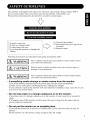
SAFETY GUIDELINES
................................................................
CONTENTS
................................................................................
FEATURES
................................................................................
STANDARD
ACCESSORIES
......................................................
INSTALLATION
INSTRUCTIONS
..............................................
Installation ......................................................................................................
Anti-tumble measures ....................................................................................
Componem Names ........................................................................................
Installation and Cabling ................................................................................
Handling the Remote Controller ....................................................................
OPERATING
INSTRUCTIONS
..................................................
Ttlrning Power On and Off ............................................................................
Input Selection ............................................................................................
Volume Adjustment ....................................................................................
Sound Mute ..................................................................................................
Comrast Adjustmem ....................................................................................
Input Signal Status Display ..........................................................................
On-Screen Display System, EasyMenu ......................................................
OTHER FEATURES
..................................................................
Automatic store ..........................................................................................
Reset (Settings initialization) ......................................................................
Signal Check ..............................................................................................
Power Save Mode ......................................................................................
Sound Mode ................................................................................................
TROUBLESHOOTING
..............................................................
Symptoms That Seemingly Appear to be Failures ......................................
Actions to Correct Abnormal Displays ......................................................
PRODUCT
SPECIFICATIONS
..................................................
Signal Input ................................................................................................
Recommended Signal List ..........................................................................
Notes
about
• The information
This
I
1
2
2
3
3
3
4
6
8
9
9
10
10
10
11
11
12
20
20
21
21
22
22
23
23
25
2"1
28
29
Manual
in this manual
is subieat
to change
without
notice.
• While meticulous
care has been taken in the preparation
of this manual, you are requested
to notify your dealer or us should you have any comments, views or questions about our
product.
• Fully understand the prerequisites
to using the product, such as hardware and software
specifications
and constraints,
in using the product.
We are not held liable for damages
caused by improper handling of the product.
• Reproduction
of this manual in whole or in part without our prior written permission
is
prohibited.
• The product names mentioned
in this manual may be trademarks
or registered trademarks
of their respective owners.
Thefollowing
features
areprovided
bythecolor
Plasma
Display
Monitor.
Large-screen, high-definition
plasma display panel
The 42-inch color plasma display panel, with a resolution of 1024 (H) x 1024(V) pixels, creates
a high-definition,
large-screen
(aspect ratio : 16:9) and low-profile
flat display.
Free from
electromagnetic
interferences
from geomagnetic
sources and ambient power lines, the panel
produces high-quality
display images fi-ee from color misconvergence
and display distortion.
Multimedia
input support
The monitor comes complete with a mini-D-sub
terminal and a BNC terminal for RGB input
and with a composite/S
terminal and a component
tenTainal for video input, and even with
stereo audio input terminals. It allows hooking up with a number of devices, from PCs to video
gear.
Multiscan
converter and Flexible Control LSI
The multiscan converter provides a broad multiscan range of signals, from video signals (15
kHz) to PC analog video signals. Video input is subjected to signal processing by a dedicated
LSI to offer better video quality.
Easy-to-use
remote controller
and EasyMenu
The remote controller included eases the work of setting display controls. Further, the on_
screen display system, EasyMenu, displays the status of signal reception and display control
settings in an easy4owiew fashion.
Power saving system
The international ENERGY STAR,2_ power saver feature saves power consumption
automatically when input signals are not available. When connected to a VESA DPMScompliant PC, the monitor cuts its power consumption while it is idle.
• This product is complete with the display monitor, plus the accessories
below.
• If any of these accessories is missing, please contact your dealer.
shown
÷lg
User manual
(this book)
Remote-control
transmitter
Size AA
batteries x2
Power cable
D-subSignal
mini-15_pin
cable,
• Read the user manual (this book) and keep them in a safe place for handy
• Retain the packing materials for use in future shipping or relocation.
Warranty Card
reference.
• To preser_ e the performance of this product and to maintain safety, always use one
of the special mount units for installation.
Special
mount
units
(options):
Wall Mount
(MPAKI4),
Unit (horizol_tal-mount
C MPAK04,
(eiling
Mount Unit ((MPAT04)
vertical-mount
i
• Use one of the special mount units to install this product.
A mount of
insufficient
strength or inadequate
design Call cause overturning
or dropping
and result in fire, electrical
shock or il!imy. Please note that oilr company
assulnes
absolutely
no responsibility
tbr personal iltjuries or propel_y dalnage
caused by use of other nlount units or improper
instalh_tion.
/IX WARNING
|
/
• Installation
of the wail lnouni unit and ceiling mount unit can be dangerous,
so do not attenlpt this work yourself. Ask your dealer to provide the name of
a qualified
installer.
an internal temperature increase, nlaintain a
Z_ CAUTIONS • Inordertoprevent
spaceof
10cln (4 inches) or more between
the sides and other
etc., so that the ventilation
boles are not blocked.*
CAUTION
this
tunlbling
unit
mounted
down
to avoid
in
a stable
possible
place.
physical
Take
nleasul'es
iitj ul_y.
to
such as walls,
prevent
it
fl'Olll
I
I
1
"Ha_e
ol_iects
Securing
to a wall or pillar
1)Using a comnlercially
pillar.
Securing
available
......_,0_,,,o,_
_md clamp,
secure
the set to a firm wall or
desktop
1)Using wood screws
stand as shown.
2)Using
cord, chain
(t'¢,,o), I:asten the set to tile chmq)ing
commercially
available
Using the optional
wood
screws,
secure
vertical-mount
screw
holes
the set filmly
on ttle rear of'the
in positkm.
unit (CMPAKI4)
Using tile optional wall-mount
unit (CMPAK14)
allows set to mount on wall surlSces
as
shown at right.
l/Make a_ least fbur sets of commercial ancbor bolts and screx_ s a_ ailable to meet _arious kinds of
v_aNs
to lrloullt
o_1
2) Read tbe instructions supplied _ith the _ aIl-mount unit carefully to optlmal[y locate the plasma
dispIay on a _aII surthce
3) Prepare the _aIl surthce tbr _ncbormg and drilling as needed, as shown m tbe sketcbes
• Make sure that an adequate _aIl surfhce strength and a screw hoIdhlg strength are ax ailable
• k p_)er I_f_wr_i_l mou _ting
AX CAUTION
sur_a_
I
III
mc
I
_m
• The unit, when
should
switch
Otherwise,
m
mounted
have the power
_t its bottom.
ma elevated
internal temperature
rise
could cause the unit _o
fi61 or fire.
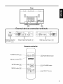
Front
Cabinet
(front frame)
Remote-controI
receiver _]
Control panel
_stment
buttons
are located on tbe
bottom.
/
si_
_E_U
S_L_C_
_7 VOlUblE /X
S:l_ FOWE_
ub
/
er b_tton _
VOLUME button _q
SELECT button _1
MENU button _1
INPUT SELECT button _1_1
Indicating
lamp_-_
Main power
switch
_
Rear
[z[z
[z[z
[z[z
[z[z
[z[z
[z[z
[z[z
°[z[z
[z[z
[z[z
°
IDDDDDDDDDDD
DDDDDDDDDDD
DDDDDDDDDDD
I
External device connection terminals
I
:xternal speaker
terminals
•
Video input terminals ___]
RGB input terminals
_]
[--?1
Remote controller
POWER butto_
RGB/VIDEO
button
RECALL button
MUTE button
VOLUME button
MENU button
SELECT button
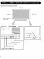
Connecting
to a PC
• Read SAFETY GUIDELINES
( _] to _'h]) carefully to ensure maximum safety
before proceeding to these steps:
1) Make sure that the display signals produced by your PC meet the specifications of this
product.
• For the specifications of this product, see Product Specifications ( _2fflto _2_61).
2Choose an appropriate site and install the product on a level table where the stand is secure.
• Install the monitor to have ready access to a power socket.
3) Make sure that your PC's power switch is off.
4) Interconnect the signal input tmrainal (RGB 1) on the monitor rear panel and the display
signal output terminal of the PC to each other using the signal cable included.
• Optional cables are needed to connect to the RGB2 input and audio input terminals.
• If the signal cable included does not match your PC, consult your dealer after reading the
section "Signal lnput'L _2_]
5) Insert one end of the power cable included into the rear-panel power cable connector and
the other end into a mains.
6) Turn on the monitor, then the PC to make sure that a display image appears on the monitor
screen.
• For instructions on taming on the monitor and adjusting its display images, see
"Operating Instructions" (_'9] to _'_9]).
£
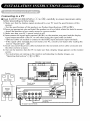
Connecting
(such
to Video Equipment
as a Laser Disc
• Read
player,
a DVD
player,
a DSS,or
a Video
Camera)
GUIDELINES
(_V] to _V'H_
) carefully to ensure maximum
safety
to these steps:
an appropriate
site and install the product on a level table where the stand is
SAFETY
before proceeding
1) Choose
secure.
• install the monitor to have ready access to a power socket available.
2) Make sure that the video equipment's
power switch is off'.
3) Interconnect
the signal input terminal on the monitor rear panel and the video equipment's
signal output terminal to each other using an commercially
available video cable.
4) Insert one end of the power cable included into the rear-panel
power cable connector and
the other end into a power socket.
5) Turn on the monitor, then the video equipment's
to make sure that a display image
appears on the monitor screen.
• For instructions
on turning on the monitor and adjusting its display images, see
"Operating
Instructions"
( _]
to _]
Speaker
).
Video
equipment
(such as a video disc player,
a DVD player and a video came O
-
+'_+I
l+-t.,
c
_U_e if the video
equ pr]e t has an
S video ipIdt tem]i al
• If video equipment with an S video output terminal is used, cabling by the S video cable is
recommended
to provide finer video quality.
(if an S video input terminal and a video input
terminal connect to the monitor at the same time, S video input would govern.)
• If video equipment is equipped with component
video output (Y, PLs,PR or Y, C_s, Cr), please
connect to the corresponding
color (Y, Pts, PR) input jack on the component
input of the
monitor.
NOTE
: Y to Y, Pl+-Cl+ to Pl+, PR-Cr to Pm
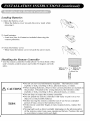
Loading
Batteries
1) Open the battery cover.
• Slide the battery cover towards
pressing it.
2) Load batteries.
• Load two Size AA batteries
correct polarities.
the arrow
included
mark while
observing
the
3) Close the battery cover.
• Slide back the battery cover towards the an-ow mark.
Handling
the Remote
• Use the remote
unit's
sides.
controller
remote-control
Controller
within
sensor
about
and within
5 m from front of the
30 degrees
on both
About 5m
CAUTIONS
TIPS
• Do not use new and old batteries together.
The batteries could
explode or leak, resulting in fires, physical iniury, or stains.
• When loading batteries, observe their correct polarities as marked
the product, if loaded in the wrong direction, the batteries could
explode or leak, resulting in fires, physical injury, or stains.
on
• Do not drop or impact the remote controller.
• Do not splash the remote controller with water or put it on a wet
object to avoid possible failures.
• Before leaving the remote controller
out of use for an extended
period of time, remove the batteries from it.
• If the remote controller begins to lack responsiveness,
replace the
batteries.
• Strong light such as direct sunlight impinging on the photoreceptor
of the remote control can cause operational
t_ailure. Position this unit
to avoid direct contact with such light.
• To turn on the main unit power supply, main unit the MAIN POWER switch (@)
of the main unit to ON and then press the SUB POWER button or the POWER
button of the remote controller.
• To turn offthe main unit power supply, press the SUB POWER button of the main
unit or the POWER button of the remote controller, then set the MAIN POWER
switch (@) to OFF.
• [:'or normal operations, leave the main power switch (@) set to ON and use the sub power
switch or the Power button of the remote controller to turn the power on and off.
Indicating lamp
Power status
Off
Off
Lights red
Off
(standby)
Lights or blinks
green
On
Operating
When the main power switch @ is set to
OFF,
When the main power switch @ is set to
ON and Power button of the remote
controller or the sub power button on the
control panel located at the front part of
the bottom plate is off.
When the main power switch @ is set to
ON and Power button of the remote
controller or the sub power button on the
control panel located at the front part of
the bottom plate is on.
When the indicating lamp blinks in green or the message
"POWER SAVE" or "OUT OF FREQUENCY" appears on
the screen, there is something unusual about the status of
reception. See "Symptoms That Seemingly Appear to be
Failures." _1
o
II tx._llMNn
power
switch
%_in
• Avoid repeatedly
intervals.
TIPS
turning
the monitor
unit
%
oao_t_,ll_
_
on and off at short time
• Failures might result fi-om such operation.
• Ttlrn off the main power switch (@) before
leaving
the monitor
out
of use for an extended period of time.
• If a power failure occt_rs while the main unit is rtmning, it would be
powered on upon recovery from the failure. Turn off the unit main
power
switch before
leaving
the main
unit.
• Press
theRGB/VIDEO
buttonontheremote
controller
ortheINPUTSELECT
buttononthemainunittoswitchtheinputinthesequence
ofRGBI->RGB2->
VIDEOI -> VIDEO2 -> RGB 1,
• When
thesame
signal
isinputtoRGB1
and
RGB2,
thephase
mayinsome
cases
shift
slightly
butthisisnotamalftlnction,
insuch
case,
readjust
thePHASE
oftheonebeing
used.
Remote
RGB1
controller
RGBI
VI_E0
(D-sub input)-_
_,
RGB2
mainunit VIDEO1
SELECT
NPUT
(BNC input)
(compositeorSinput)
_,
VIDEO2
(COMPONENTinput)
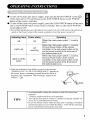
• While the on-screen display system, EasyMenu ([_1) is not on display, press the
remote controller VOLUME button [SZZ]or [5_ (or the main unit VOLUME button
• or • to adjust the sound xolume,
• The adiustment
status will be displayed as
guidance while you press these buttons.
• While the guidance is on display, press
or • to turn up the volume.
• While the guidance is on display, press
or • to turn down the volume.
Remote
controller
Sound volume setting
VOLUME
Main unit
•
VOLUME
• You can also adjust the sound volume setting
via the on-screen display system, EasyMenu
÷
•
%
17 1.
: 30
ll_[_
Adjustment
status
guidance
• The sound volume adiustment mode will exit when no keys are entered for 5 seconds. (The
adjustment status guidance will disappear automatically.)
• Press the remote controller
• When you press the button,
status of volume setting will
guidance image.
• While the sound is muted,
turn down the volume.
• While the sound is muted,
cancel the mute.
MUTE button to mute the sound temporarily.
[MUTE] (pink) and the
be displayed in a
press the [5Z]button
Sound voIume setiing
to
Remote
controller_auTe
MUTE
press the E_button
to
You can also adjust the sound volume setting of the
mute via the on-screen display system, EasyMenu
K3
I_ZZZ]P.
: 30
+
(The display will turn to pink.)
071.
• Press the remote controller MUTE button once again and the mute will be cm_celed and
the guidance will chm_ge to VOLUME (blue), enabling the volume to be heard.
• When MUTE is used, the guide display will continue for 5 sec. and then turn off.
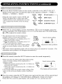
• While the on-screen display system, EasyMenu _], is not on display, press the
remote controller SELECT button <:3 or [> to adjust the contrast,
• When you press these buttons, the status of
contrast adjustment and the input horizontal
Remote
controller
+¢
o
(H) and vertical (V) frequencies
of the input
signal will be displayed in a guidance image.
• While the guidance is on display, press the <3
key to narrow the difference
between darkness
and brightness.
• While the guidance is on display, press the [:>
key to widen the difference between darkness
and brightness.
• You can also adjust the contrast setting via the
on-screen display system, EasyMenu
Press
display
•
Press
once
the remote
controller
the status
the remote
again
of input
RECALL
signals
controller
to exit the screen
button
CONTRAST : 100
Contrast setting
RGB
CONTRAST
: 100
4_!_+
• The contrast adjustment
mode will exit when
no keys are emered for 5 seconds. (The
adjustment
status guidance will disappear
automatically.)
•
VIDEO
Input ve_rtical
frequency
frequency
Adjustment
to
status guidance
VIDEO
on the screen.
RECALL
display,
button
VIDEO2
Remote
controller
REC/4C
[COMPONEN"q
•
F_7
• The EasyMenu
will clear 5 seconds
Input terminal
later.
name
RGB
RGB1
i
H : 46 5kHz,
Input horizontal
frequency
[D SLIB]
V : 60 0Hz
i
Input vertical
frequency
11
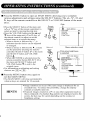
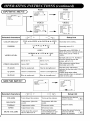
• Press the MENU button to open an MAIN MENU allowing you to complele
various adjustments and settings using the SELECT buttons (The /x, _, <3, and
[2>keys of the remote controller or the SELECT or VOLUME button of the main
unit.).
Pink
memo[e
• Press the SELECT button of the main unit
(/x or _
key of the remote controller) to
select an item by moving the pink text.
• Press the VOLUME
button and the • and
the
remote control) to adjust or set the
• keysofthemainunit(<lor[>keyof
selected item, or to switch the menu.
• When a choice is followed by ":", it
controller
E:_,_u
I_.,)
_
@
SELECT
L_
Menu selection
O
VOLUME
mark
Pink when brightness
-- is selected
PICTUREMENU
CONTRAST
: 127
COLOR
TINT
0
0
SHARPNESS
•
• Press the MENU button once again to
exit the MAIN MENU.
• The MAIN MENU will close automatically
when no keys are entered for 10 seconds.
IP i
_
Main unit
MENU
((_
• When [RETURN]
is selected, press the
remote-controller
button SELECT <3 or
the main unit SELECT button and
VOLUME button • to exit to the
and setting
MENU
SOUND
DISPLAY
FUNCTION
indicates that the choice can be adjusted
or changed.
• When a choice is followed by _', a menu
can be opened by pressing the remoter
controller SELECT button [> or the main
unit SELECT button and VOLUME
button •.
• Fororiginal
information
menu on adjusting
choices, see _
to _1"
ip_uR_AIN
•
PICTURE
OPTIONS
%
RETURN
0
MODE
: NORMAL
Guidance
• Image retention can occur if the same image is displayed for an
extended time. To reduce this possibility,
change the display
contents at suitable intervals.
HINTS
• if special images created on a PC or any other equipment (such as
those composed
of a checker-flag
pattern) are displayed across the
screen, the hue may be varied depending
on the contrast or
brightness
setting.
( PICTURE
MENU
)
RGB
VIDEO
MAIN MENU
S©_ND
DISPLAY
FUNCTION
COLOR
TINT
SHAR£NESS
P_CTURE MODE
©£TIONS
RE,_URN
OPTIONS
RETURN
0
0
0
S_JPER
'l'+
Selected
characters
CONTRAST
BRIGHTNESS
COLOR
TINT
SHARPNESS
_S
_
Setup
hint
Narrows the gap between
brightness and darkness,
Broadens the gap
between brightness
darkness,
Black is subdued for
increasedoverall
darkness,
Biack is set off for
increased overall
brightness,
Adjust to prevent black from
spreading across the
screen.
Lightens colors.
Darkens colors,
Adjust for desired density,
somewhat for lighter colors
for a natural look.
Enhances red and
weakens green,
Enhances green and
weakens red.
Adjust for a nice looking
skin color.
Softens display images.
Sharpens
Normaliy set to middle, and
towards - for increased
and
display images,
Adjust for maximum
visibility to suit the ambient
brightness.
softness.
PICTURE
MODE
Set to NORMAL
Set to SUPER
Normaliy
set to SUPER.
13
RGB
RGB
Q OPTIONS
MENU
)
oP r £)N$ ME_4U
OL()R
_EE
]
USER
GAMMA
22
'IDEC_ LEV&L
MA_NMENU
O_,t
B GAN
REY URN
255
UgER
VIDEO
{'G_IRAS_
VIDEO
12Z
dDEO LE_L
dDE C_EN _N_- E
G r_N
2_5
B GAN
REY URN
255
Selected characters
COLOR SELECT
_C_MAL
ON
Setup hint
COOL--NORM
_WARM_USER
f .0 -,_
GAMMA
2.2 -._
Normally set to COOL.
2.8
Normally set to 2.2.
VIDEO
Normally set to NORMAL. If
white is found to spread across
the screen, set to +10% or
+20%.
RGB
Normally set to 0.7 V. If white is
found to spread across the
screen, set to 1.0 V
VIDEO LEVEL
get to 0.7 V.
Set to 1.0 V.
Set to OFF
Set to ON
ON enhances vertical lines.
Normally set to ON.
R-GAIN
Red is weakened.
Red is strengthened.
G-GAIN
Green is weakened.
Green is strengthened.
B-GAIN
glue is weakened.
Blue is strengthened.
Sets the color adjustment
selected by the user with COLOR
SELECT.
USER mode takes effect
automatically when an attempt is
made to set a gain.
VIDEO ENHANCE
(SOUND
MENU
)
SOU_DMENU
VOtUM_
20
BALA_E
0
TREBLE
0
PICTURE
DISPLAY
FUNCTION
MUTELEWL
_IN
Selected
characters
_>
VOLUME
Turns
Setup
the volume.
Turns up the volume.
BALANCE
Suppresses
sound.
right-side
Suppresses
TREBLE
Suppresses
treble.
BASS
Suppresses
bass.
MUTE VOLUME
down
0
MEnU
hint
Adjust for the desired
sound volume.
_.01
left-side
sound.
Enhances
treble.
Enhances
bass.
Adjust to taste.
I-urns down the sound
Turns up the sound
Varies the sound volume
/olume.Minimum O.
volume.Maximum
premute sound volume,
when the MUTE
button is pressed.
_]
Q DISPLAY
MENU
(RGB)
)
RGB
DISPLAy MENU
PICTURE
OISpL&y
SOUND
AUTO ADJUST
MANUAL ADJUST
FN_bLa_
• i
INTE
AREA
NORMAL
R pOLATION
LENEAR
DISP LAy 1NET
RETORN
I
MAENMENU
• NORMAL
1,+
_D
Selected characters
Setup hint
NORMAL_H.
DISPLAY AREA
-- FULL _
ADJUST
AUTO
ADJUST
Set to FULL to display
images across the screen
for gaining an overview of
the overall images.
ZOOM
OK?
Adjusts the CLOCK,
PHASE, etc. automaticaJly.
*
Bet to YES.
Set to NO.
Set to DOUBLE.
Set to LINEAR.
Set to DOUBLE to see
INTERPOLATION
characters or images crisp
or to LINEAR to view them
smooth.
INITIALIZE?
DISPLAY INIT.
* Depending
adjustment.
}et to NO.
Exits to the DISPLAY
MENU, without clearing
the menu adjustment
values.
on the type of signal displayed, displays
Apply MANUAL ADJUST to optimize
* 1080/60i signal
this case.
Displays
Set to YES.
3lears all DISPLAY MENU
_diustment values exep[
NSPLAY AREAand exits to
he DISPLAY MENU.
doesn't
According
Resolution
Display
exit the display
to Selected
Overall display
FULL
of AUTO
Clear the user signal preset
data.
may not be optimized
them.
ADJUST.
DISPLAY
Apply
_2TI
through
MANUAL
automatic
ADJUST
in
AREA
Partial display
NORMAL
640 X 480 (VGA)
ZOOM
Data area
800 X 600 (SVGA)
1024 X 768 (XGA)
SXGA
X:Y=5:4
1280 X 1024 (SXGA)
1600 X 1200 (UXGA)
Others
X:Y=4:3
downward
scrolling.
15
Q MANUAL
AD,IUST
MENU
(RGB))
RGB
RGB
MAIN
MENU
PCTRE
SOUND
V POSIT ©N
CLOCK
PHASE
F NCI©N
RET
0
0
0
RN
4_ID+
Selected
characters
E>
(_
Setup
Moves the horizontal
,osition to left.
Moves the horizontal
position to right.
Adjust the left-side display
_osition.
H .POSITION
Moves down the verticat
,osition.
Moves up the vertical
)osition.
V.POSITION
Adjust the vertical display
)osition.
CLOCK
Reduces the dot clock
frequency (shrinks the
right side),
increases the dot clock
frequency (expands the
right side).
PHASE
Slows the dot clock
phase (shifts slightly to
left),
Advances the dot clock
phase (shifts slightly to
right).
( DISPLAY
hint
MENU
(VIDEO))
_IN
_IGTURZ
SOUND
Adjust for maximum
character clarity.
Adjust for clear character
visibility.
VIDEO
MZNU
v size
FUNCV]ON
O,
pL#y
0
INIT
RETURN
•
Selected
characters
DISPLAY
SIZE
_
_
4 --:3 _
_FULL
PANQRAM
D
_+
Setup
PANORAM. -'_b-_MOvlEf
_
MOVIE2 _
hint
Select to suit the aspect
ratio of the video software.
V.POSITION
3ANORAM/MOVlEf/
MOVIE2)
Adjust the vertical position
when subtitles cannot be
read.
V.SlZE
3ANORAM/MOVlEI/
MOVIE2)
Adjust until the black band
(blanking) at the top and
bottom is no longer visible.
• Componet
modes.
/ S signal
• For component
FULL.
(videol
(HD1 : 480p)
input) and componet
signals,
(SD1 480i)
the display
mode
signal applicable
is selectable
for all size
among 4:3, MOVIEI,
and
• For component
(HD3:1035i,
1080i, 720p) signals, the display mode is not selectable.
• If an S 1 or $2 image is input fi-om the S image of video I , the S 1 image would be set to
FULL, and the $2 image would be set to MOVIEI.
Displays
by Selecting
When you want to
Play a 4:3 image in a 16:9 screen
fNthful[y
Play a 4:3 image ina 16:9 screen
with the height and width of the
midNe of the screen enlarged on
equN scales and with both sides
appearing somewhat enlarged
The 16:9 WSTA size image in the
4:3 image is fNthfully reproduced
on the 16:9 screen
the DISPLAY
Set the display
size to
SIZE
Input signat
4:3
Remsrks
Blanking occurs
on both sides
PANOR.
(Panoramic)
(4:3
signal /
• The 4:3 image is called a [etterbox
image
. [n some cases, some slight
blanking may remain at the top
MOVIE1
(Vista)
The 21:9 Cinema size image in the
4:3 image is expanded veNcNIy on
the 16:9 scleen
Display
screen
and bottom
in some cases, some slight
Nanking may remain at the top and
bottom
MOVIE2
(Cinema)
Play a 4:3 image faithfully in a 16:g
screen in the standard vertical size
and horizontally squeezed*
* An image with an aspect ratio of
16:9 shrunk horizontNly to 4:3 to
display in a 4:3 screen
FULL
(Squeez)
TIPS
Using a wide-screen
monitor
• This monitor has a screen mode selection
t'eature. If an incompatible
screen mode is
selected to play Cellain sofb,_,are, such as a TV program,
the image would appear dit'f)rent
from the original. Take this into consideration
when making screen mode choices.
• Use of this monitor in its enlarged
display mode with the wide feature enabled in coffee
shops, hotels and other establishments
for commercial
or pubic viewing purposes
could
infringe on the copyrigh* holder's
righ* protected
by Copyright
Law.
• When a normal 4:3 image is displayed
over the entire screen in the PANOR.
mode, not the
Wide mode, parts of the periphery
of the image may disappear
and/or appear distolied
in
solne cases. Use the 4:3 mode to view images, which were crea*ed in 4:3 nlode.
This mode allows 4:3 content to be viewed without picture distortion.
17
Q FUNCTION
MENU
)
RGB
MAIN MENU
P_CT_RE
SOUND
DISpLAy
MODE
SCREEN SAVER
_ET_RN
•
Selected
characters
LANGUAGE
AUTO FREQ.
(RGB input only)
(_
_
VIDEO
PC
ENGLSH
_@
COMPONENT
VIDEO SYSTEM
AREA1
SCREEN SAVER
_ET_RN
• ENGLISH
,+
D
Setup
hint
EN_,_NGUSH)
_
D (DEUTSCH)-,IH_-ITAL (ITALIANO) The
defautt is ENG
ESP (ESPANOL)-gHm,-FRA(FRAN_AJS)_
(English).
get to OFF
The frequency of a new
_ignal is not displayed
"eceived.
Set to ON.
The frequency of a new
signal is displayed as it is
received.
MODE
(RGBinputonly)
PC _
MOVIE
Set to OFF if you find the
frequency display appearing
upon signal change
annoying.
The mode function added to
the Function Menu atlows
for a smooth playback of
movies from 60 Hz XGA
input when it is set to
MOVIE.
Normally, keep the function
menu set to PC (OFF
mode). Set g to MOVIE
(ON) when playing movies.
LINE
INTP.
3D COMB
Set to OFF.
Set to ON.
Set to ON when playing a
3D-video disc. Set to OFF
in most cases.
Set to OFF.
Set to ON.
Set to OFF if video images
appear unnatural. Set to ON
in most cases.
N-PAL-q_b-AREAf
M-PAL
AREA2
4-NTSC
NTSC
VIDEO SYSTEM
SECAM--_4_PAL
Swgch the color system to
suit the input system in
video input mode VIDEOf.
• Normally, set to AREAl.
The input signal system
will he automatically
recognized to display input
images on the screen
(Japan, Europe, and North
America). (Choose
AREA2 in South America.)
• If the input signal contains
much noise or has a low
level at AREAl, 2 and the
operation is found erratic,
set to match the input
system.
( COMPONENT
MENU(VIDEO)
)
VIDEO
VIDEO
CO_4pC_E_T
MNU
CO_,IpOt_
NTSDI Ct_Cr
CO_,IpOt_
NTSO2 Ct_Cr
CO_,IpOt_
NTHD_ Cb_Cr
CQMPOt_
NT HD2
CQMPOt_
NT HD3
RET
CbiCr
Selected characters
COMPONENT
_S
_
pbfPr
pbfPr
R_4
•
•
+
Pb/Pr
Setup hint
SD1
(480i)
COMPONENT SD2
(European SDTV)
COMPONENT
(480p)
HD1
COMPONENT
HD2
The default is YlCblCr.
Set to Cb/Cr to suit
the Y/Cb/Cr signals.
Set to Pb/Pr to suit the
Y/Pb/Pr signals.
(720p)
The default is Y/Pb/Pr.
COMPONENT HD3
(10801)
"SCREEN
SAVER
M^I_ MENU
P_CTUEE
£OU_D
DISPLAy
MENU )
RGB
VIDEO
FUNCTION MENU
LANGUAGE
ENG
AUTOF_EQ
ON
[SCFIEENSAVER
,]
LANGUAGE
ENG
LINEINTP
OFF
3DCOM_
ON
SCReEN SAVER MEnU
OE_TER
OFF
MOVING DOT_
2
_*OV]NGT_ME_
10
IrCVERSE
_OFF
WHITE
_OFF
RETURN
COMPONENT
V]DEOSYSTEM
RETURN
Selected
characters
ORBITER
_
FUNCTION
AREA1
blENU
_D
_
Setup
Set to OFF.
Set to ON.
hint
Set to ON when high bum-in
)otential exists such as static or
stiil image displayed for a long
)eriod of time.
1_2_3
MOVING DOTS
MOVING TIMER
Reduces the amount
of movement,
Increases the amount
of movement.
Reduces the time
intervah
Increases the time
interval.
Adjust as desired.
Shift time can be set from 1 min to 60
min (Use zero (0) to check the shift
range
Shift time will be approx
Normally
if 60 is selected, the set enters a power
wait state 60 minutes later, with its settings
INVERSE
60 -_-
WHITE
1 sec)
set to OFF
OFF
-_-
ON
canceled When a still picture has been
displayed for bng before ON is selected to
display the same still picture, iNVERSE or
WHITE helps prevent the still picture from
baking into the panel The set stops when
input signal flow is interrupted
19
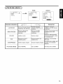
• Approximately 1 sec. after adjustment is completed, the adjustments will be
recorded as shown in the table below,
Item
Sound
volume
Sound balance
Treble
Bass
Mute volume
Input status automatic
display
Line correction
Three-dimensional
Y/C
separation
HD signN
Language selection
Display
VOLUME
BALANCE
TREBLE
BASS
MUTE LEVEL
AUTO FREQ.
Registration
condition
One
set
can
be
Reproduction
condition
During normal signat
eception.
recoFded.
LINE INTP.
3D COMB
COMPONENT
LANGUAGE
One set can be recorded
during common RGB1,
Contrast
CONTRAST
Brightness
Color temperature
Gamma correction
Input signal level
BRIGHTNESS
COLOR SELECT
GAMMA
VIDEO LEVEL
Color
COLOR
RGB2 input; one set of
two can be recorded
during normal signal
reception with common
VIDEO 1, VIDEO 2 input.
One set can be recorded
Tint
Sharpness
TINT
SHARPNESS
during common VIDEO
VIDEO 2 input.
Display area
Display size
Horizonal position
Vertical position
Dot clock frequency
Dot clock phase
Vedcal size
DISPLAY AREA
DISPLAY SIZE
H.POSITION
V.POSITION
CLOCK
PHASE
V. SIZE
One group can be
recorded for each signal
mode.
During normal signat
reception.
During normal signat
1, reception.
During recording and when
[he same signal mode is
detected.
• The previously recorded items will be lost.
• The signal mode can be identified by the horizontal/vertical
sync frequency and the sync
signal polarity. Different signals with which all the elements are the same or similar will be
handled as the same signal
• RGB 1 and RGB2 inputs have common elements that can be recorded for each signal mode.
Because of this, when the contents are recorded with RGB 1 (or RGB2), there may be loss
of adjustment dm-ing RGB2 (or RGB 1) reception in the same signal mode.
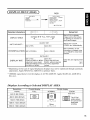
• The EasyMenu shown to the right will be displayed when the SELECT button is
used to select DISPLAY and moreover
DISPLAY INIT is selected from the On-screen
INITIALIZE ?
Display System Easy Menu _Jl • If the <3 key
(select YES) of the SELECT button is pressed
YES ,1_ +NO
at this time, the user adjustment values in the
table below for the signal currently being
received will be deleted and the factory settings
will be restored,
• Pressing the [2>key (select NO) cancels deletion and returns the DISPLAY MENU.
DISPLAY menu item
Horizontal
Vertical
Dot clock
Dot
Display
position
H.POSITION
position
Vertical
RGB1,
V.POSITION
frequency
clock
Application
RGB1,
RGB2,
RGB2
VIDEO1,
CLOCK
RGB1,
RGB2
phase
PHASE
RGB1,
RGB2
size
V. SIZE
VIDEO1,
VIDEO2
VIDEO2
• Changes in the signal status are displayed on the screen as they arise.
RGB
Status
The input signal was
switched or the
RECALL button was
iressed after AUTO
FREQ was turned on
Action
Display
• The input temlinal
horizontal
RGB1 [D SUB]
H : 46 5kHz, V : 600HZ
and the
and vertical
frequencies
a guidance
are displayed
image
VIDEO
in
VIDEO1
• The guidance message
"POWER SAVE" is
displayed
seconds
A sync signal could not
be detected
for about 5
• Check the power switch of
the PC and its status of
• In the event of continued
absence
Egher VIDEO or S VIDEO is
displayed on VIDEO input
of a sync signal,
POWER
the power indicating lamp
flickers and the monRor
SAVE
enters power save mode
The input signal does
not meet display
specifications
or erratic
• The guidance message
"OUT OF FREQUENCY'
displayed
is
• Check the input signal
specifications
OUTOFFREQUENCY
once again
21
•
When the RGB input jack is selected
• When this unit is connected
to a VESA DPMS computer, the Power Save (Off) mode can
be set to be activated automatically
when the computer is not being used to reduce power
consumption
by this unit.
Horizontal
Yes
No
Yes
No
Yes
Yes
No
No
RGB sync signal
Vertical
Video signal
Operation
mode
Indicating [amp
Power consumption
Active
(normal display)
Blank (no video)
On
Off
Lights green
Blinks green
450W (standard)
6W or less
• When the Video Input jack is selected
When there is no video
consumed
by
signal input, the power-saving
system
operates
to reduce
the power
the sunit.
Video signal
Screen display
Operation
mode
Indicating lamp
Power consumption
Yes
No
Active (normaldisplay)
Blank(no
video)
On
Off
Lights green
Blinks green
450W(sNndaN)
6Worless
• If you press the MENU bulton while the monitor has power save mode lurned of'l;
sound output is enabled by cancelling the off setting of power save mode.
• When the monitor enters sound
mode indication on the screen.
mode, it displays
a
Remote
con[roller
• In sound mode,
sound volume
can be adjusted,
• Press the MENU button to cancel sound mode.
• Power save mode is enabled when sound mode is
canceled.
• If an input signal is available, the monitor displays the
input signal by canceling sound mode automatically.
SOUND
MODE
mm ,,_u
Remote
controller
E_
"%)
POWER
SAVE
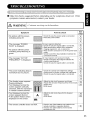
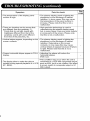
• Make the checks suggested below depending on the symptoms observed. If the
symptoms remain uncorrected, contact your dealer,
WARNING
"Customer
servicing
Symptom
• No picture
indicating
Point
with the powerlamp off.
• The message
"POWER
SAVE" is displayed.
• No picture
indicating
green.
with
the power
lamp flickering
• The message
FREQUENCY"
in
"OUT OF
is displayed.
• The power indicating
lamp
normally
lit but no picture.
is
I
can be hazardous.
to check
See
page
• Check the way the power cable is connected.
[-'.61
• Press the power switch.
[-'.71
No sync signal is detected.
• Check the way the signal cable is connected.
• Make sure that the switch of the computer,
_1
_]
equipment,
etc., isisnot
turned
on.power-save
• imaging
Make sure
the computer
in the
_1
mode.
• Check to see if the input selection matches the
connecfion terminal
_2_1
An input signal is not received normally.
• Check to see if the input signal matches the
monitor specifications.
_1
• Check the way the signal cable is connected.
_2j_
• Check the contrast and brightness settings
(adjust them for higher contrast and brightness).
• Check the way the signal cable is connected.
_
_2Jl
_1
_7--]
F1j
• The display image
flowing slantwise.
• Text displayed
screen appears
streaked,
in vertical
appears
across the
vertically
phase next.)
(RGB input)
_.61
_2_1
with the characters
columns
blurred.
• Text displayed
across the
screen appears
blurred,
• A fine pattern flickers when
displayed
• Adjust the dot clock frequency and phase.
(Adjust the dot clock frequency first, the dot clock
on the screen,
i
i
j
A
• Adjust the dot clock phase for the clearest
viewing.
(RGB input)
[1_1
_-2.61
i_
i
L
The remote
controller
does
not work.
• Check to see if the batteries are loaded in the
remote controller in opposite direction.
• Check to see if the battedes in the remote
controller are OK.
_8-1
23
Symptom
• The temperature
surface is high.
Point to check
of the display panel
• The plasma display panel is lighting the
phosphors by the discharge of internal
radiation. In some cases, this may cause
the temperature of the panel surface to
increase. Please note that this is not a
malfunction.
• There are locations on the screen that
are different from the periphery (*).
• Points that do not light, points with
brightness different from that of the
periphery, points with color different
from that of the periphery, etc.
• High-precision technology is used to
manufacturing the plasma display panel
but, in some cases, there are minor defects
in some parts of the screen. Please note
that this is not a malfunction.
• Vertical stripes appear, depending
screen contents,
• The plasma display panel is lighting the
phosphors by the discharge of internal
radiation. Depending on the screen
contents, in rare cases this may cause
vertical stripes to appear because of failure
to light. Please note that this is not a
malfunction.
on the
• Coarse horizontal stripes appear in FULL
display,
• The display dims to make the picture
invisible during special playback of a VCR
(FF, hEW).
• Adjusting the phase wilI reduce the
horizontal stripes.
(RGB input)
, This condition may occur when the unit is
connected to a VCR with component output,
such as 480i, but it is not a failure. But when
it occurs, switch to composite output or Sl
(S2) output).
See
page
• Depending on the kind of system equipment used, images may not be displayed
normally. In this case, make the adjustments suggested below,
Symptom
1
Text displayed across the screen appears vertically streaked,
(display 1/.
The display image appears flowing (display 2 / (RGB input/.
.VertiCal
Display 1
with some characters
blurred
8eforeadj_stmer_
Some characters
are blurred
Example
crisp no,Jr
N_rred
1) Press MENU button to open the MAIN MENU.
2) Press SELECT button_ several times to choose DISPLAY.
3) Press D" to open the DISPLAY MENU.
4) Press _ to choose AUTO ADJUST.
5) Press []>. (ADJUST OK)
(Adjust the by displaying a fine pattern, such as a character string, or vertical streak
pattern across the screen.)
If AUTO ADJUST does not work.
Adjustment
procedure
6) Press MENU button to open the MAiN MENU.
7) Press SELECT button _ several times to choose DISPLAY.
8) Press D to open the DISPLAY MENU.
9) Press _ to choose MANUAL ADJUST.
10) Press [Z> to open the MANUAL ADJUST MENU.
11 ) Press _ several times to choose CLOCK.
(Adjust the clock by displaying a fine pattern, such as a character string, or vertical streak
pattern across the screen.)
12) Press _ or <:_ to make the text appear uniform across the screen.
13) If the text appears bJurred across the screen, make the adjustment instructed in
Symptom 2.
• The display image may be momentarily
failure.
disturbed during clock adjustment but this is not a
25
Symptom
2
text displayed across the screen appears Murred in its entirety (display 2).
_.fine pattern flickers when displayed on the screen (display 3).
Display
2
Bo_r_
_d,,_,,oo_
Display
...........
3
Bo_oo
_j_t_ot
@
Example
A_ler adju&tment
A_e_ adjastment
I) Press MENU button to open the MAIN MENU.
2) Press SELECT button _
several times to choose DISPLAY.
3) Press D" to open the DISPLAY MENU.
_) Press _ to choose AUTO ADJUST.
_) Press
(Adjust
pattern
f AUTO
Adjustment
procedure
D'. (ADJUST OK)
the by displaying a fine pattern, such as a character
across the screen.)
ADJUST does not work.
string, or verticat streak
_) Press MENU button to open the MAIN MENU.
7) Press SELECT button _
several times to choose DISPLAY.
3) Press [> to open the DISPLAY MENU.
3) Press _ to choose MANUAL ADJUST.
1O)Press [_> to open the MANUAL ADJUST MENU.
11) Press _ several times to choose PHASE.
(Adjust the phase by displaying a fine pattern, such as a character string, or verticat
_treak pattern across the screen.)
12) Press D
or <:_ to make the text appear
clean across the screen,
12) Press D
or <] to make the text appear
w thout f cker ng.
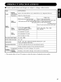
• Product
specifications
are subject
to change
without
notice.
CMP412OHDUS
Type
Display
Panel
and designs
Approx. 42 inches (922 mm (H), vertical 522 mm (V), diagonal
1059 ram)
dimensions
Resolution
1024 (H) x 1024 (V) pixets
Input
_erminals
RGB onedine two input terminals
(D-sub 15-pin) (BNC)
RGB audio twodine two input terminals
(left, right)
RGB input
VIDEO
input
Video
Video
Video
Video
1 video input terminal
1 audio input terminals 0eft, right)
1 S video input terminal
2 video input terminals
(Y) (Pb/Ch / (Pr/Cr)
Video 2 audio input terminals 0eft, right)
Input
signals
Video
signals
0.7 V/1.0 Vp, analog RGB
(horizontal: 24kHz to 106kHz,
vertical: 50Hz to 85Hz)
NTSC, 480i, 480p, 720p, 1080i,
PAL, SECAM
HN separate, TTL levet
Sync
signals
HN composite,
TTL levet
Sync on green, 0.3 Vp-p
Recommended
Signal
24 modes _-29_
Audio output terminal
8W + 8W
Input power
AC100 - 120 / 200 - 240V(automatically
Power consumption 450W (typ.)
External dimensions
1,037 (W) x 648 (H)x 89 (D) (ram) (excluding
Mass
36.6kg (including the stand), 33 kg (excluding
Ambient
conditions
selected)
5A / 2.5A
the stand)
the stand)
Temperature
Operating
: 5"C to 35'C, Storage : 0'C to 40'C
Relative
humidity
Operating
: 20% to 80%, Storage : 20% to 90% (non-condensing)
• The monitor
takes at least 30 minutes
to attain the status
of optimal
picture
quality.
27
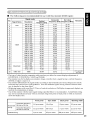
• RGB terminal (D-sub 15-pin connector)
Pin
1
input signal
R. video
2
3
G. video or sync on green
B. video
4
No connection
5
No connection
6
R.GND
7
G.GND
8
B.GND
g
No connection
• When
10
GND
1t
No connection
12
[SDA]
13
H. sync or HAt" composite sync
14
V.sync. [V.CLK]
15
[SCLI
• RGB terminal
Sync
kinds of input signals
signal
HNseparate
type
sync.
HNcompositesync.
sync.on
Green
(BNC connector)
@ ©
V.sync.
different
©
H. sync or H/V
composite
sync
• S-input connector
B. video
pin specifications
Pin
input signal
1
Y
2
Y-GND
3
C
4
C-GND
Frame
GND
• Serial connector pin specifications
Pin
input signal
1
No connection
Remarks
2
RXD0
Unit _ PC
3
TXD0
Unit _ PC
4
5
GND
No connection
6
GND
7
No connection
8
No connection
Frame
GND
are
simultaneously
input to the monitor via a
graphics board or the like, the monitor
will automatically
select the signals in the
following priority order:
Unit GND +4 PC GND
@ @
G. video or sync
on green
R. video
Priority
t
2
3
• The following are recommended
for use with this moniter (RGB input):
Signal mode
No,
Horizontal
frequency (kHz)
Dot clock
frequency (MHz I
640 X 400
Vertical
frequency (Hz)
70.08
31.47
25.18
3
640 X 480
640 X 480
59.94
72.81
31.47
37.86
25.18
31.50
4
5
6
640 X 480
640 X 480
800 X 600
75.00
85.01
56.25
37.50
43.27
35.16
31.50
36.00
36.00
7
8
800 X 600
800 X 600
60.32
72.19
37.88
48.08
40.00
50.00
9
10
800 X 600
800 X 600
75.00
85.06
46.88
53.67
49.50
56.25
13
1024 X 768
1024 X 768
1024 X 768
60.00
70.07
75.03
48.36
56.48
60.02
65.00
75.00
78.75
14
15
1024 X 768
1280 X 1024
85.00
60.02
66.68
63.98
94.50
108.00
16
17
1280 X 1024
1280 X 1024
75.03
85.02
79.98
91.15
135.00
157.50
18
19
2O
1600 X 1200
1600 X 1200
1600 X 1200
60.00
75.00
85.00
75.99
93.75
106.25
162.00
202.50
229.50
21
22
23
640 X 480
832 X 624
66.67
74.55
35.99
49.73
39.24
57.28
1024 X 768
1152 X870
75.11
75.06
60.24
68.68
89.09
100.00
1080i
59.94
33.72
Signal Name
1
VGA
T
11
12
VESA
Macintosh
24
25
1080 / 6Oi
Resolution
Remarks
HN separate
sy_iconly
• The type of video board or conneciing
cable used may not allow fbr correct displays adiustmem
of
H.POSITION,
V.POSITION,
CLOCK and PHASE.
• The monitor may I:ail to display an animation
image correctly when a signal having a vertical frequency
of 85Hz or higher is input to it.
• The monitor ditI?rentiates
the signal modes according
to the horizontal
and vertical frequencies
and the
horizontal
and vel_ical sync signal polarities.
Note that different signals having all these elements
alike
may be handled as the salne signal.
• Displaying
images with more than 512 lines of vertical resolution
at Full diplay (compressed
display) can
result in the interpolation
of stripes.
• Use of this monitor with the input signal timings specified
below is recommended.
A predefined
setting
may not be reproduced
correctIy
with an extremely
long front porch or back porch or with an extremely
short data display time.
Front porch
Sync width
Back porch
Blanking
width
Horizontal frequency
24 kHz to 52 kHz
0.2 ps or more
1.0-4.0 0 s
1.2 ps or more
3.5 0 s or more
Horizontal
timing
Horizontal frequency
52 kHz to 106 kHz
9.2 ps or more
0.8-3.9 # s
1.1 tJs or more
2.3 # s or more
9 # s or more
25 ps or more
400 ps or more
450 I_S or more
Vertical timing
29
HITACHI
Hitachi America, Ltd.
Home Electronics Division
1855 Dornoch Court
San Diego, CA 92154
Tel : 1-800-HITACHI
(1-800-448-2244)
QR48631
All Rights Reserved
Printed in Japan