1
GemCad User's Manual
Version 4.51
by
Robert W. Strickland
May, 1992 Revised August 24, 1992
HTML version of manual: December 14, 2000
Dedication
GemCad is dedicated to the memory of my father
Robert L. Strickland
who introduced me to faceting.
Acknowledgements
I gratefully acknowledge the many suggestions of Walter Carss, Bob Long, Norm Steele, Greg
Thompson. I thank all of the GemCad users whose continued suggestions have helped me to
improve the program. I thank my wife, Dorothy, who let me put in the long hours on GemCad
and helped me proofread this manual.
Copyright©1992, 2000
Robert W. Strickland.
All rights reserved.
Contents
Introduction
Tutorial
Lesson 1
Lesson 2
Lesson 3
Lesson 4
Reference Manual
File Menu
Cut Facets Menu
Point Menu
Edit Menu
Utility Menu
Diagram Menu
Configuring GemCad
Error Recovery
Using GemCad with a Mouse
Introduction
This manual describes GemCad 4.0, a computer-aided design program to assist in designing
faceted gem cuts. GemCad simulates a faceting machine. You can specify angles and indexes,
and GemCad will cut facets on the screen, drawing the stone at each stage. This is valuable for
checking the validity of published faceting diagrams. Although GemCad simulates a faceting
machine, its real purpose is to do the "grunt work" of designing new gem cuts. GemCad can
figure out the angle of a facet given two points and its index, and it can figure out the angle and
index given three points. You can specify meet points on the screen with the cursor keys or the
mouse. GemCad understands radial and mirror-image symmetry. If you tell it to cut one facet, it
will automatically cut the other facets on the tier. GemCad can scale a stone, adjusting the angles
for different indexes of refraction. GemCad can turn a round design into an elliptical one.
GemCad can produce formatted listings suitable for use as faceting diagrams.
GemCad is written in the C programming language and was compiled with Borland's C++.
GemCad runs on an IBM PC™ or compatible with at least 512KB of memory and VGA, EGA,
Hercules™ or CGA graphics adapter card. (The CGA resolution of 640X200 is a bit sparse, but
is sufficient for many designs.) An 80x87 numeric co-processor is strongly recommended but not
required. A hard disk is also strongly recommended. GemCad supports a Microsoft Mouse or
compatible. The driver supplied with your mouse (such as MOUSE.COM) must be loaded before
running GemCad. This is most commonly done in the AUTOEXEC.BAT file, but may be done
anytime at the DOS prompt. GemCad will not work with a MOUSE.SYS device driver such as is
loaded in the CONFIG.SYS file.
To run the program, type GEMCAD at the DOS prompt. The program will try to detect which kind
of graphics adapter card you have, but if your screen is messed up, try again by typing GEMCAD X
where "X" specifies the graphics adapter and is one of the characters "c" for CGA, "e" for EGA,
"h" for Hercules, "v" for VGA. This will bypass the auto-detection software and will hopefully
get things going in the right direction.
GemCad can be "driven" with the function keys, legends for which appear at the left of the
screen. Legends beginning with ">" change to a new menu of functions. You can also point at a
function key legend with the mouse and click a mouse button to activate it. The Help (h) key
(Function key F11 [or Shift-F1] in every menu) followed by another function key will print a
short description of what that key does (when it is NOT preceded by the F11 key).
To install the program onto your hard disk, I recommend making a subdirectory called GEMCAD
on your hard disk and then copying all of the files to that directory. If your hard drive is C: and
your floppy is A:, do the following at the DOS prompt:
C:
CD \
MD GEMCAD
CD GEMCAD
COPY A:\*.*
GemCad Tutorial
Lesson 1
To run GemCad, type GEMCAD at the DOS prompt. GemCad will print its version number and
copyright notice. After you press any key or mouse button to acknowledge the message,
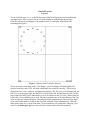
GemCad will switch your display to the graphics mode. Your display should then look
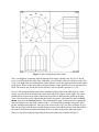
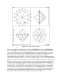
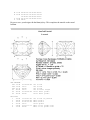
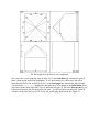
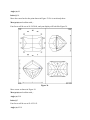
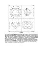
something like Figure 1.
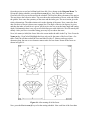
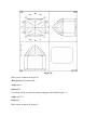
Figure 1. Display when GemCad is first run
This is an actual screen dump with a VGA display. (An EGA display will look slightly less
resolved vertically, and a CGA will look considerably less resolved vertically.) The screen is
divided into four views, similar to an engineering drawing. The Top View is at the upper-left, the
Side View is at the upper-right, the End View is at the lower-left, and the Bottom View is at the
lower-right. The index gear is indicated by a circle of numbers in the Top View. When GemCad
is first run, a 64-tooth index gear is used. The index positions start at 64 at the bottom of the Top
View and increase counterclockwise. This rather peculiar orientation was chosen to keep facets
cut at small index numbers visible in the Top, Side, and End Views simultaneously. This will
make better sense as we cut our first stone. (You can make the I.D. position be at the top if you
want. See the Index gear (g) key in the reference section at the back of this manual.))
While working through this tutorial, be careful not to press the standard alphabetic keys unless
responding to questions that GemCad asks. Most of the alphabetic keys are shortcuts for
commands that we shall learn to execute with the function keys. Caps Lock should also be
turned off (the light should not be lit) since there are more commands than letters, and
commands performed by pressing capital letters are generally more dangerous than commands
performed with lower-case letters.
What better way to learn than by doing! Let's begin with a standard round brilliant in quartz. We
will use 44° for the pavilion mains and 40° for the crown mains. A round brilliant has eight-fold,
mirror-image symmetry and can be cut on a 64 index gear. These are the default settings when
GemCad is first run. (You can change the symmetry with the Symmetry (y) command described
in the reference section of this manual.) We shall begin by cutting girdle facets at 90° to preform
the stone. At the left of your display you will notice the title "MAIN MENU" and several lines
beginning with F1-F6 that correspond to the function keys on your keyboard. The function keys
will be along the left or top of your keyboard depending on the model. In the Main Menu, all of
the labels begin with the > character indicating that selecting the corresponding function key will
move to a different menu. Now, experiment with moving around in the menu structure by
pressing the function keys corresponding to labels starting with > If you are using a mouse, you
can also point at one of the function key legends to cause it to "light up." Then press any mouse
button to execute the highlighted choice.
You will notice single alphabetic characters to the right of function key labels. These are
abbreviations for the corresponding function key commands. Typing the alphabetic key is
equivalent to pressing the corresponding function key. So what's the shortcut if either takes but a
single keystroke? The advantage is that you don't have to be in any particular menu to execute a
command with an alphabetic key. This saves you the trouble of wandering through the menu
hierarchy if you already know the commands since all the commands are available all the time. If
you type reasonably well, the alphabetic keys might be easier to locate than the function keys.
Remember to be sure that CAPS LOCK is off (the light is not lit) since upper-case commands are
different from (and generally more dangerous than) lower-case commands.
The help key is F11 (or Shift-F1) in every menu. If you press the Help (h) key followed by
another function key, GemCad will print a one-sentence description of what the key does. This
tells what the key does when it is not preceded by the Help (h) key. You should have received a
sheet of paper listing all of the menus. (A file called MENUS.TXT contains the same information.)
Use this for a road map as you explore the menus. After you have explored the menus, get back
to the Main Menu by pressing the >Main Menu function key.
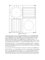
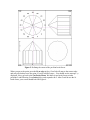
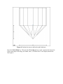
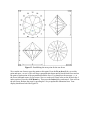
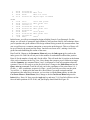
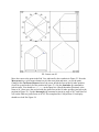
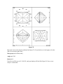
Figure 2. Girdle facets
Cutting is done while in the menu called Cut Facets Menu. To get to the Cut Facets Menu
from the Main Menu, press the >Cut Menu key. We shall begin by cutting 16 girdle facets at
90° to preform the stone. (GemCad can handle only faceted or knife-edge girdles--it cannot
handle a round girdle.) Using a 64 index, the girdle facets are at indexes 2, 6, 10.... To tell
GemCad to cut at index position 2, use the Index (i) key. You will see the question, "Index?"
appear at the top of your screen in dark letters on a white background. Enter 2. (That is, press the
2 key and then press the key labeled Enter.) You can correct mistakes with the Backspace key
any time before pressing Enter. Any time GemCad needs a response from you, it will prompt
you at the top of the screen. After you enter the 2, you will notice the message i2.0 in the status
box at the lower-left-hand corner of your screen. This portion of the screen contains information
about facets about to be cut.
Now we need to tell GemCad at what angle to cut the facet. To do this, press the Angle (a) key.
GemCad will ask "Angle?" at the top of the screen. Enter 90. (Press the 9 key, the 0 key and then
the Enter key.) You might notice the message a90.00,i2.0 appear briefly in the status box at
the lower-left-hand corner of your screen while GemCad cuts the sixteen girdle facets! Your
screen should look like Figure 2. GemCad knows to cut sixteen facets because it is set for eightfold, mirror-image symmetry. (These are the default settings, but they may be changed easily.)
GemCad will cut a facet or course of facets as soon as you have given it enough information. In
this case, we specified the index, angle. For the other facets we will cut later, we will also have
to specify a cutting depth, but for this first tier of facets, a reasonable cutting depth is assumed.
The fundamental rule of GemCad is that it cuts a set of facets as soon as you give it enough
information to completely specify one of the facets.
The four views of the stone are projections of the stone onto the faces of a cube. The advantage
of cutting facets in the Top View is that the x coordinate is shared with the End View and the y
coordinate is shared with the Side View. Neither axis of the Bottom View aligns with any of the
other views.
A word about correcting errors in entry: Entering two different indexes will cause the first index
to be discarded. If you make a mistake entering the index, simply enter it again. If GemCad has
just cut a facet that didn't come out as you hoped, you can use the Undo (u) key found in several
of the menus. This will undo the previous command that changed the stone. The Undo (u)
command only undoes the last change to the stone. The undo command will not undo itself. If
GemCad is busy cutting off facets or otherwise taking longer to do something than you might
expect, press the Esc key to interrupt. This will automatically perform an undo.
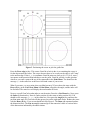
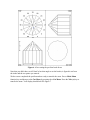
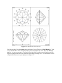
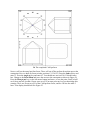
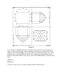
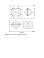
Now back to our brilliant. We shall cut the pavilion mains next. We need to indicate to GemCad
at what depth to cut the mains. You specify the cutting depth of a facet to GemCad by entering
one or more points on the facet-to-be. You specify points to GemCad by moving the cursor
around on the screen and by making choices in the Point Menu with the function keys. Now go
to the Point Menu by pressing the >Point Menu key.
The cursor is located at the intersection of cross-hairs on the screen that look like a + sign. To
move the cursor around on the screen, you can use either the arrow keys on the calculator-style
numeric keypad or the cursor keys (if your keyboard has them). The odd numerals 1, 3, 9, and 7
on the numeric keypad make the cursor move diagonally. If the numeric keys on your keyboard
are the same keys as the cursor keys, it doesn't matter whether or not the Num Lock key is active.
Now experiment with moving the cursor around. The cursor accelerates if held down--that is, the
step size increases the longer you hold down a key. GemCad can also make use of a Microsoft or
compatible mouse (most are). If your mouse doesn't do anything, its probably because you have
not loaded the driver software supplied with your mouse. See the section on mice at the end of
the reference section of this manual.
Move the cursor down to near the center of the End View. If you press the space bar, GemCad
will draw a pair of dotted lines across the screen intersecting at the cursor. This allows you to
line up things in different views. Move the cursor so that it aligns horizontally with the dot at the
center of the Bottom View and so that it aligns with the vertical edge of the girdle facet at the
center the End View. (Pressing the space bar again will remove the previous cross-hairs.) When
the cursor is in the End View, it specifies the x and z coordinates. When it is aligned horizontally
with the dot at the center of the Bottom View, the z coordinate is zero. Your cursor should be
positioned as in Figure 3.
Figure 3. Positioning the cursor to pick the girdle line
Press the Pt on edge (e) key. This causes GemCad to look in the view containing the cursor is
for the edge nearest the cursor. The cursor does not have to be exactly on the edge; it will "snap"
to the nearest edge. If the (x, y, z) coordinates GemCad prints are close to (0.0, 1.0, 0.0), enter y
in response to the question about whether to use the point. GemCad will ask you this question
whenever you enter a point with any of the commands in the Point Menu. You should see the
message 1pt in the status box at the lower-left-hand corner of your screen.
What if you enter y to use a point when you didn't mean to? If you redraw the stone with the
Draw (d) key in the Cut Facets Menu or Point Menu, all points, the angle, and the index will
be discarded. The status box will display the total number of facets.
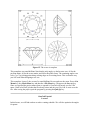
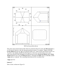
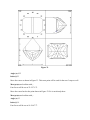
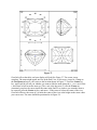
Now we can tell GemCad at what index to cut the mains. Press the >Cut Menu key. Next, press
the Index (i) function key. Enter 0. (Index position 0 is the same as index position 64.) You
should see the message 1pt,i0.0 in the status box. Now press the Angle (a) key and enter the
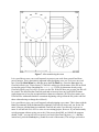
pavilion main angle 44. GemCad will then proceed to cut the eight main facets. Redraw the stone
with the Draw (d) key. Your screen should look like Figure 4. The Draw (d) command updates
the dimension lines. The List to scrn (l) command gives the numerical values of various ratios
of the dimensions indicated by the abbreviations.
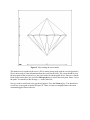
Figure 4. After cutting the pavilion mains
Now, you might be wondering what the bottom of our stone is doing in the Top View. Not to
worry: we will transfer the stone later. Generally, you will find it easiest to cut facets on the Top
View. You might also be wondering how GemCad knew to cut only eight main facets but sixteen
girdle facets. Since we are using mirror-image symmetry, index position 64 (or 0) is mirrored by
itself. The same is true for the star facets which we will cut at index position 4, 12, 20....
Now we will cut the pavilion break facets. Instead of telling GemCad at what angle to cut the
breaks, we will tell GemCad where to cut the facet and have it figure out the angle. The cursor
should still be near the meet point of the main facet at the 64 index and the girdles in the End
View. (You don't have to be right on the meet point, just near it.) Press the key labeled >Point
Menu. Now press the Meet pt (m) key. The cursor should "snap" to the nearest meet point and
ask you whether to use the point. Answer with a y if GemCad has found the meet point of the
girdles and the main at index 64. Now move the cursor to the Top View. How far down do you
like your pavilion break facets to extend? Some faceters prefer about half way from the girdle to
the culet. I prefer them cut about two-thirds of the way down to the culet. Move the cursor
wherever you desire along the right edge of the main at index 64 as shown in Figure 5.
Figure 5. Defining the extent of the pavilion break facets
When you get to the point, press the Pt on edge (e) key. GemCad will snap to the nearest edge
and ask you whether to use the point. If you're satisfied, enter y. You should see the message 2pt
displayed. Next, go back to the Cut Facets Menu. We shall cut our break facets at index
positions 2 and following. Press Index (i) key and respond with 2. After GemCad cuts the 16
break facets, your screen should look like Figure 6.
Figure 6. After cutting the pavilion break facets
Note that you didn't have to tell GemCad at what angle to cut the breaks; it figured it out from
the index and the two points you entered.
We have now completed the pavilion and are ready to transfer the stone. Press >Main Menu
function key and then go to the Cut Menu by pressing the >Cut Menu. Press the Xfer (x) key to
transfer the stone. Your display should look like Figure 7.
Figure 7. After transferring the stone
It is a good idea to save your work frequently to protect your work from yourself and from
power-outages. This is particularly important when designing a new cut. Let's save our work
now. Press the Main Menu key and then press the File Menu key. Press the Save (s)as key.
GemCad will ask you, "Project name?" GemCad is asking you for the name of the file in which
to store the project. Enter something like lesson.gem. If a file by that name already exists,
GemCad will ask you if it is O.K. to write over the file. If the file does not yet exist, the file will
be created. The data files that GemCad reads and writes may have any legal DOS file name
(eight characters or less plus an optional three character extension). (It's best for to name your
GemCad files with names that have extensions beginning with g so that the file picker can find
them without having to change the wildcard.)
It is a good idea to save your work frequently when designing a new stone. This is done with the
Save (s) command. With the Save as (S) command, GemCad will always ask you for the file
name, whereas with the Save (s) command, GemCad only asks if you haven't yet given it a
name. It will still ask if it's O.K. to write over an existing project, however. If you inadvertently
exit the program without saving your work, if the power should fail, or (forbid!) the program
should "crash," you can still recover most of your work. Run GemCad press Enter and then
immediately press the Undo (u) key (found in several of the menus). This will get you back to
just before the last change. To save its work, GemCad uses a file named GEMCAD.BAK in whatever
directory from which it was run. It updates this file whenever you make a change to the stone.
Note that the undo command will not undo itself.
Lesson 1 is now complete. You might want to take a break now to let the stone and your brain
cool off a bit. If you have used the Save (s)as command and specified a project name and the
status message "Saved" has been printed in the upper-left-hand corner of your screen, it's safe to
exit the program. This done with the Quit (Q) selection in the File Menu.
GemCad Tutorial
Lesson 2
Welcome back. In this lesson we shall cut the crown of our round brilliant. Run the GemCad
program. Press the File Menu key to get to the File Menu. Now we need to open the project.
Press the Open (O) key to reopen the project. GemCad will ask you for the name of the project
(file). Here, you could type in the name of the project, but just respond by pressing the Enter
key, and GemCad will activate a file picker. This allows you to open projects by clicking on their
names with the mouse or by selecting them with the cursor keys. You should see the name of the
current directory printed at the top of your display. You should see the entry labeled file spec
at the top of the column of files. You should also see the name of your file and perhaps other
GemCad files. If you don't see your file name one of two things could have happened. If you
didn't gave your file name an extension that doesn't begin with G, the file will not be matched by
the wildcard. If this is the case, click on file spec and change the wildcard to *.*. Now, all of
the files in the current directory will be visible, including your project file. If not, you are
probably not in the same directory as you were when you saved the file at the end of the last
lesson. You can navigate through the directory tree by selecting the directories that end with the
backslash \ character. The special directory ..\ is the parent of the current directory, and
clicking on it moves closer to the root of the directory tree.
So, when you locate your project, move the cursor box around with the mouse or cursor keys to
highlight your file name. Then press a mouse button or the Enter key. The stone should look the
same as when you saved the project at the end of Lesson 1 as shown in Figure 7.
Now we are ready to cut more facets. Press the >Main Menu key to return to the Main Menu
and then press the >Cut Menu key to get to the Cut Facets Menu. We shall now cut our crown
mains at index position 64 at an angle of 40°. Press the Index (i) key and enter 0 for the index.
Now, enter the angle by pressing the Angle (a) key and entering 40. Now we must enter a point
on the facet. In order to see more clearly to position this facet precisely, we can zoom in on the
End View. Move the cursor down to the girdle line on the End View. Then press the Zoom (z)
key. GemCad will enlarge the End View to fill the entire screen. Move the cursor to where you
want the main at index 64 to meet the girdle facets--decide how much girdle to leave by eye. The
cursor should be positioned as shown in Figure 8.
Figure 8. Position the cursor to define the girdle thickness
Press the >Point Menu key. Then press the Pt on edge (e) key to pick a point on the facet-to-be.
If the cursor snaps to the edge you wanted, enter y to cut the facets. Your display should look
like Figure 9.
Figure 9. After cutting the crown mains
The mains meet at a point on the crown. (We're cutting cheap rough with an oversized preform.)
We are now ready to enter information about the crown break facets. The cursor should be near
the meet point of the crown facet we just cut at index 64 and the girdle facets. Since we want the
break facets to meet here also, press the Meet pt (m) key to select this meet point. Enter y to use
the point. You should see the message 1pt in the status box.
Now we need to zoom back out to get the big picture. Press the Zoom (z) key. You should now
see all four views again as shown in Figure 10. There are only two magnifications--the zoom
command toggles between the two.
Figure 10. Zoom out to see the big picture
Now we must decide how large to make the crown break facets. Instead of entering the angle
explicitly, we shall let GemCad figure it out. Let's make a construction line to assist us in placing
these facets. The minus key (the hyphen or -) is used to draw construction lines. The Constr line
(-) command is also found in the Utility Menu. Let's draw a line. Move the cursor away from the
stone and press the - key. Move the cursor again and press the - key again. GemCad will draw a
dotted line from the first point to the second point. (You can use the Draw (d) command to erase
construction lines.) Position the cursor in the Top View near the meet point of the main at 64 and
the girdle. To help you position the cursor, you can press the Meet pt (m) key to snap the cursor
to the meet point. Enter n (or simply press the Enter key) to discard the point. (Here we are only
using the Meet pt (m) key to snap to the meet point quickly.) Press the - key to begin our
construction line. Next move the cursor near the meet point of the main facet at index position 16
and press the Meet pt (m) key to snap to the meet point. Press Enter to discard the point. Next,
press the - key to draw the construction line. Now move the cursor near the intersection of the
construction line and the edge formed by the intersection of the mains at indexes 64 and 8. (The
edge will align radially with the 4 index position.) Your cursor should be positioned as shown in
Figure 11.
Figure 11. Position the cursor to set size of mains
If we enter a point on the edge at the intersection of the construction lines we will end up with
about a 60% table. If you want a smaller table, move towards the center of the crown a bit. When
you have the cursor where you want it, press the Pt on edge (e) key to set the point. If the cursor
moves only slightly to snap to the edge, enter y to tell GemCad to use the point. You should see
the message 2pt at the lower-left-hand corner of your screen. (If it says 1pt then you forgot to
enter the meet point of the main at 64 and the girdle facets about four paragraphs back.) Now we
need to tell GemCad at what index to cut the facet. Press the >Cut Menu key. Press the Index (i)
key and enter "2" as the index. GemCad should proceed to cut the 16 crown break facets, and
your display should look like Figure 12.
Figure 12. Crown mains and breaks
Now we are ready to cut the star facets. Press the >Point Menu key to go to the Point Menu.
The cursor should still be at the intersection of the main and break facets along the radius of the
stone at the 4 index position. Press the Meet pt (m) key to enter the point and press y to use the
point. Now we shall make two more construction lines. We want the line to begin at this meet
point, so press the - key to start the construction line. Next move the cursor near the
corresponding meet point along the radius at the 52 index position. Press the Meet pt (m) key to
snap to the meet point, but press Enter to discard the point. (Again, we are only using the Meet
pt (m) key to position the cursor quickly; we don't want our star facet at index 4 to meet here.)
Press the - key again to draw the construction line. Now we shall make another construction line.
Move the cursor near the meet point of the mains and breaks along the radius at the 60 index
position and press the Meet pt (m) key to snap to the meet point, and press Enter to discard the
point. Press the - key to start a new construction line. Move the cursor near the corresponding
meet point along the radius at the 12 index position, press the Meet pt (m) key to snap to the
point, press Enter to discard the point and then press the - key to draw the construction line. The
two construction lines should intersect on the main facet at the 64 index position. Move the
cursor to this point of intersection. Your display should look like Figure 13.
Figure 13. Establishing the meet point for the star facets
We want the star facets to meet the mains at this point. Press the Pt on facet (f) key to set this
point and enter y to use it. This will drop a perpendicular down until it hits the main facet and set
the point of intersection of the perpendicular and the facet. You should see the message 2pt at
the lower-left-hand corner of your screen. Now we need to tell GemCad to cut the facets at the 4
index position. Press the >Cut Menu key. Then press the Index (i) key and enter 4. Gem will cut
the star facets. Redraw the stone by pressing the d key to update the dimension lines. Your
display should now look like Figure 14.
Figure 14. After the star facets are cut
Now for the table. Press the Angle (a) key and enter 0 (zero). Press the >Point Menu key. Your
cursor should still be at the meet point of the main at 64 and the star facets. Press the Meet pt
(m) key. As soon as you enter y GemCad will cut the table. Note that you only had to enter the
angle zero and not the index since index has no meaning for angle zero. You should now see the
completed brilliant cut on your display as in Figure 15.
Figure 15. The crown is complete
This completes our round brilliant. Note that the only angles we had to enter were 44 for the
pavilion mains, 40 for the crown mains, and 90 for the girdle facets. The remaining angles were
set by "eye" by picking points along existing edges or on existing facets. This is often the way
you will work when designing a new cut.
This completes Lesson 2, the crown of a round brilliant. Be sure and save the stone: Press >Cut
Menu key, the >Main Menu key and then the >File Menu key. Then press the Save (s) key.
Since we specified the project name when we opened it, GemCad will not ask you for a file
name. GemCad will tell you that the file already exists and ask you if it's O.K. to write over the
file. After saving the project, quit the program by pressing the Quit (Q) key.
GemCad Tutorial
Lesson 3
In this lesson, we will find out how to make a cutting schedule. We will also optimize the angles
for quartz.
Open the project to read our brilliant back from disk. Now, change to the Diagram Menu. To
list out the cutting schedule, press the List to scrn (l) key. Let's study this for a moment.
GemCad will clear your screen and list the schedule. The first line shows the name of the project.
The next shows the refractive index. The next shows the total number of facets, with and without
the girdles. Next come the symmetry of the stone and the index gear. The next section gives the
relative dimensions. The abbreviations refer to the drawing of the stone. Next, comes the facet
data. Each tier of facets is shown on a separate line. The angle of the tier (in degrees) is given,
and then the index of each facet is given. All facets in a tier are cut at the same angle and cutting
depth. Unfortunately there is no way to tell which line goes with which tier. We will remedy this
shortly. After you have viewed the listing, press any key to redraw the stone.
Now, let's name (or label) the facets. Move the cursor inside the table in the Top View. Press the
Name (n) key. GemCad will highlight the facet ask you for the name of the facet. Enter T for
table. GemCad will then redraw the facet and label it with a T. Names can be up to three
characters long, but one or two character names make for less clutter. Name all the facets as
shown in Figure 16.
Figure 16. After naming all of the facets
Now, press the List to scrn (l) key to list the cutting schedule. Now each line of the facet data
begins with the name of the corresponding tier. You can name two facets on a tier with different
names, but only one will be printed in the listing.
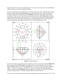
Now let's analyze the optical performance of our stone. Move the cursor inside the table near the
perimeter of the table and press Waytwace (w). GemCad will trace the ray into the stone and
back out. (The raytrace command is in the Cut Menu.) Repeat the same for the star and the
crown break facets. If your screen becomes too cluttered, redraw with the Draw (d) command.
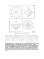
In particular consider the rays shown in Figure 17. On your screen, the portion of the rays inside
and outside the stone are shown in different colors. Light entering the stars, mains and breaks
leak out the pavilion. Only light entering the table is returned through the crown.
Figure 17. Some light rays
Now let's lower the angles. Move the cursor inside one of the crown mains. Press the Blink facet
(b) key (located in the Utility Menu. The angle of the facet will be shown in the box in the
upper-left-hand corner of your screen and should be 40°. Now let's scale the crown to make this
angle 27°. Make sure the cursor is still inside a crown main and press the Tan ratio (T) key.
(This command is in the Cut Menu.) GemCad will tell you what the old angle was and ask you
for the new angle. Enter 27. GemCad will immediately rescale the crown.
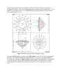
Next, move the cursor inside a pavilion main and change the pavilion mains from 44° to 42°. The
smaller angles are near those recommended by Long & Steele and result in a much better
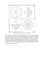
performance for quartz. Now, use the Waytwace (w) command to check the performance. You
should see rays similar to Figure 18. All light entering vertically through the mains, and stars
now exits through the crown.
Figure 18. Paths of light rays after changing the angles
Execute the Playback (P) command (in the Utility Menu). GemCad will show an animation of
the stone. The completed stone should look like Figure 19. You can list a cutting schedule to
your printer by moving to the Diagram Menu and pressing the List to file (L) key and entering
PRN for the file name. The resulting schedule should look like the listing in Table 1, but the
angles might be a bit different since their numerical values were not entered but were set by
"eye."
Figure 19. The completed brilliant
LESSON.GEM
Angles for R.I. = 1.54
57 facets + 16 facets on girdle = 73
8-fold, mirror-image symmetry
64 index
L/W = 1.000 T/W = 0.583 T/L = 0.583
P/W = 0.450 C/W = 0.108 H/W = (P+C)/W+0.02 = 0.578
P/H = 0.778 C/H = 0.187 Vol./W^3 = 0.190
GIRDLE
G 90.00 02-06-10-14-18-22-26-3034-38-42-46-50-54-58-62
PAVILION
M 42.00 64-08-16-24-32-40-48-56
B 43.31 02-06-10-14-18-22-26-3034-38-42-46-50-54-58-62
CROWN
M 27.00 64-08-16-24-32-40-48-56
B 33.08 02-06-10-14-18-22-26-3034-38-42-46-50-54-58-62
S 15.66 04-12-20-28-36-44-52-60
T 0.00 Table
Be sure to save your design with the Save (s) key. This completes the tutorial on the round
brilliant.
GemCad Tutorial
Lesson 4
CAM PREFORM
PF1 33.40
PF2 35.00
PF3 41.70
G1 90.00
G2 90.00
G3 90.00
10-38-58-86
24-72
96-48
24-72
10-38-58-86
96-48
Cut to TCP
Cut to TCP
Cut to TCP
Cut to final length
Level false girdle
Level false girdle
PAVILION
1
43.00
2
46.00
3
45.81
4
62.00
5
54.00
6
70.00
13-35-61-83
10-38-58-86
07-41-55-89
24-72
23-25-71-73
96-48
Cut to TCP of preform
Meet G1-G2-1
Meet G2-G3-2
Level girdle
Meet 2-4 at girdle line
Meet 2-3 at girdle line
7
8
9
10
CROWN
A
B
C
D
E
F
G
H
J
T
60.00
42.20
45.00
47.31
01-47-49-95
10-38-58-86
96-48
03-45-51-93
"
Meet 1-2-3
Meet 8 at culet
Adjust angle if needed
51.00
42.50
35.00
44.00
39.40
42.19
61.00
38.31
35.82
0.00
24-72
23-25-71-73
19-29-67-77
10-38-58-86
03-45-51-93
02-46-50-94
96-48
07-41-55-89
14-34-62-82
Table
Leave some girdle
Meet girdle line
"
Level girdle
Meet girdle line
"
Level girdle
Meet girdle line
"
Table
In this lesson, we will cut a rectangular design called the Formée Cross Rectangle. For this
design, we will need a Centerpoint Angle Method (CAM) preform. Briefly, this technique allows
you to reproduce the girdle outline of the design without having to make any measurements. One
cuts several facets to a common centerpoint, a meet point on the dop axis. This set of facets will
be cut off later by the actual pavilion facets. One then cuts facets at 90°, making a level false
girdle-line and establishing the outline of the stone.
Run GemCad. Change to the Parameter Menu and press the Index gear (g) key and set the
index gear to 96. GemCad will ask you for the number of teeth and the bottom index position.
Enter 96 for the number of teeth and 0 for the offset. This will make the 96 position at the bottom
of the circle of numbers in the Top View. Next, change the symmetry to two-fold mirror-image
with the Symmetry (y) command. Enter 2 and y in response to GemCad's questions about the
symmetry. Now we are ready to cut the first four facets. Change to the Point Menu and use the
Query user (q) command. GemCad will ask you for the coordinates of the point. Enter 0, 0, 1
for the x, y, and z coordinates, respectively. Enter y to tell GemCad you want to use the point.
You will see 1pt displayed in the status box. (Recall that if you make a mistake and the
information in the status box is incorrect, you can clear it with the Draw (d) key in either the
Cut Facets Menu or Point Menu.) Next, change to the the Cut Facets Menu and press the
Index (i) key. Enter 10. Now press the Angle (a) key and enter 33.4. GemCad will then cut four
facets at index positions 10-38-58-86, and your display should look like Figure 20.
20. The start of the CAM preform
For many cuts, you can just enter the angle and index of the first set of facets, and GemCad will
assume a "reasonable" cutting depth. Here, we typed in the coordinates of the centerpoint. Note
also that it was necessary to enter this centerpoint before the angle and index. For some designs
with high angle facets (about 50° or higher) the center point will be off the screen, and instead of
a centerpoint you will see what looks like a facet at the top of the stone. GemCad starts off with a
cube of rough a bit smaller than each view. The faces of this cube are not drawn, but all facets
cut will be truncated at the faces of the cube.
The four facets meet at the exact center of the Top View. This is the centerpoint to which the
other facets of the preform will be cut. Now, change to the Point Menu. Move your cursor near
the centerpoint, as shown by the crosshairs in Figure 20. Press the Meet pt (m) key (or the left
mouse button) and enter y to tell GemCad you want to use the point. Now change to the Cut
Facets Menu, press the Angle (a) key and enter 35. Then, press the Index (i) key and enter 24.
GemCad will then cut two facets at 24-72, making a total of 6 facets. Now let's cut the last pair
of facets cut to the common centerpoint. Press the Index (i) key and enter 96 (or zero). Press the
Angle (a) key and enter 41.7. Verify that you have a41.7,i0.0 displayed in the status box in the
lower-left-hand corner of the screen. If so, change to the Point Menu. Move the cursor back to
the centerpoint in the Top View, if it is not still there. Press the Meet pt (m) key. After you
enter/tt yto tell GemCad you want to use the point, GemCad should cut two more facets at 9648., and your display should look like Figure 21.
21. Facets cut to centerpoint for CAM preform
Now we are ready to cut the girdle facets at 90°. Move the cursor to the location of the crosshairs
in Figure 21. Press the Pt on edge (e) key (or the right mouse button) and enter y to use the
point. You should see 1pt in the status box. Change to the Cut Menu, and we will explore a new
command. Move the mouse cursor inside one of the facets in the Top View and press the Jam
index (j) key. You will see the index show up in the status box just as if you had entered the
index with the Index (i) command. Try it with several of the facets. Now, find the facet cut at 24
index and use the Jam index (j) key to "jam" its index in the status box. You should see
1pt,i24.0 displayed in the status box. Then, press the Angle (a) key and enter 90. GemCad will
then cut the two facets at 24-72. Your display should now look like Figure 22.
22. The length of the preform is now established
Now, move the cursor inside the facet at index 10. Use the Jam index (j) command to grab its
index. (Keep trying until GemCad displays "i10.0" in the status box.) Now move the cursor
inside the big facet at 90° in the Side View. Use the Jam angle (A) command to grab its angle.
You should see a90.0,i10.0 displayed in the status box. Now change to the Point Menu, move
your cursor to the point in the Side View as indicated in Figure 22. Press the Meet pt (m) key (or
left mouse button) to pick the meet point and enter y to tell GemCad to use the point. GemCad
will then cut the four facets at 10-38-58-86, and your display should look like Figure 23.
23. Corners cut off
Move the cursor to the point in the End View indicated by the crosshairs in Figure 23. Press the
Meet pt (m) key (or left mouse button) to pick the meet point and enter y to use the point.
Change to the Cut Facets Menu and move the cursor inside the facet at the 96 index position.
(Just a bit up and to the left of the position in Figure 23.) Use the Jam index (j) command to
grab its index. You should see 1pt,i0.0 in the status box. (Recall that index position 0 is the
same as 96.) Now move the cursor inside the girdle facet at the 10 index position (just below the
position in Figure 23). Use the Jam angle (A) command to jam in its angle of 90°, and GemCad
will cut the final two girdle facets at 96-48. This completes the CAM preform. Your display
should now look like Figure 24.
24. The completed CAM preform
Next we will cut the actual pavilion facets. These will cut off the preform facets that meet at the
centerpoint. Now we shall cut facets at index positions 13-35-61-83. Press the Index (i) key and
enter 13. Press the Angle (a) key and enter 43. You should now see/tt a43.0,i13.0in the status
box. Change to the Point Menu and move the cursor to the centerpoint as shown in Figure 24.
Press the Meet pt (m) key (or the left mouse button) and enter y to use the point. GemCad will
cut 4 facets and tell you that 6 facets were cut off. You must press any key to acknowledge this
warning. The 4 new facets cut off 6 of the CAM preform facets, and we will lose the other 2
later. Your display should look like Figure 25.
25. First four pavilion facets
Move the cursor to the location in the Side View shown in Figure 25. Press the Meet pt (m) key
(or left mouse button) to enter the meetpoint and press enter y to confirm. Change to the Cut
Facets Menu and enter an angle of 46 and an index of 10. GemCad will cut the four facets at 1038-58-86. Your display should look like Figure 26. From now on, I'll assume you are now
sufficiently familiar with changing back and forth between the Cut Facets Menu and the Point
Menu and know how to use the Meet pt (m) key command, the Index (i) key command, and the
Angle (a) key command. The remaining instructions will be in outline form.
Angle (a) 45.81
Index (i) 7
Move cursor as shown in Figure 26.
Figure 26.
Move cursor as shown in Figure 27.
Meet pt (m) and confirm with y
Angle (a) 62
Meet pt (m) and confirm with y
Four facets will be cut at 07-41-55-89, and display will look like Figure 27.
Figure 27.
Move cursor as shown in Figure 27.
Meet pt (m) and confirm with y
Angle (a) 62
Index (i) 24
Two facets will be cut at 24-72
Angle (a) 54
Index (i) 23
Move cursor as shown in Figure 27. (This is same point as used in the last step.)
Meet pt (m) and confirm with y
Four facets will be cut at 23-25-71-73, and your display will look like Figure 28.
Figure 28.
Move the cursor as shown in Figure 28.
Meet pt (m) and confirm with y
Angle (a) 70
Index (i) 96
Two facets will be cut at 96-48.
Move the cursor to the same point as before (Figure 28).
Meet pt (m) and confirm with y
Angle (a) 60
Index (i) 1
Four facets will be cut at 01-47-49-95, and your display will look like Figure 29.
Figure 29.
Angle (a) 42.2
Index (i) 10
Move cursor as shown in Figure 29.
Meet pt (m) and confirm with y
Four facets will be cut at 10-38-58-86. GemCad will warn you that these facets cut off the
remaining CAM preform facets. Your display will look like Figure 30.
Figure 30.
Move cursor as shown in Figure 30.
Meet pt (m) and confirm with y
Angle (a) 45
Index (i) 96
Two facets will be cut at 96-48, and your display will look like Figure 31.
Angle (a) 47.31
Index (i) 3
Move cursor as shown in Figure 31.
Figure 31.
Meet pt (m) and confirm with y
Four facets will be cut at 03-45-51-93.
This completes the pavilion. Change to the Cut Menu and press the Xfer (x) key to transfer the
stone. Your display should look like Figure 32.
Figure 32.
Now we need to establish the thickness of the girdle. Move the cursor to the point shown in
Figure 32. The cursor should be on the horizontal line in the Side View a bit to the left of the
girdle line. Press the Pt on edge (e) key (or the right mouse button) and confirm with y. There
should now be a vertical dotted line in the Side View, and this line should define the girdle
thickness. If the girdle thickness is not correct, redraw with the Draw (d) key, and set the point
again.
Angle (a) 51
Index (i) 24
Two facets will be cut at 24-72, and your display should look like Figure 33.
Figure 33.
Angle (a) 42.5
Index (i) 23
Move the cursor as shown in Figure 33. This meet point will be used for the next 3 steps as well.
Meet pt (m) and confirm with y
Four facets will be cut at 23-25-71-73.
Move the cursor back to the point shown in Figure 33 if it is not already there.
Meet pt (m) and confirm with y
Angle (a) 35
Index (i) 19
Four facets will be cut at 19-29-67-77.
Angle (a) 44
Index (i) 10
Move the cursor back to the point shown in Figure 33 if it is not already there.
Meet pt (m) and confirm with y
Four facets will be cut at 10-38-58-86, and your display will look like Figure 34.
Figure 34.
Move cursor as shown in Figure 34.
Meet pt (m) and confirm with y
Angle (a) 39.4
Index (i) 3
Four facets will be cut at 03-45-51-93.
Angle (a) 42.19
Index (i) 2
Move the cursor back to the point shown in Figure 34 if it is not already there.
Meet pt (m) and confirm with y
Four facets will be cut at 02-46-50-94.
Move the cursor back to the point shown in Figure 34 if it is not already there.
Meet pt (m) and confirm with y
Angle (a) 61
Index (i) 96
Two facets will be cut at 96-48.
Angle (a) 38.31
Index (i) 7
Move the cursor back to the point shown in Figure 34 if it is not already there.
Meet pt (m) and confirm with y
Four facets will be cut at 07-41-55-89, and your display should look like Figure 35.
Figure 35.
Move the cursor to the location indicated by Figure 35. (If you don't see it, look again; it's in the
Side View near the girdle line.)
Meet pt (m) and confirm with y
Angle (a) 35.82
Index (i) 14
Four facets will be cut at 14-34-62-82, and your display will look like Figure 36. Now we are
ready to cut the table.
Figure 36.
Angle (a) 0 (There is no need to specify an index for the table.)
Move the cursor to the location shown in Figure 36.
Meet pt (m) and confirm with y
Figure 37.
GemCad will cut the table, and your display will look like Figure 37. The crown is now
complete. The stone might appear too low in the End View, so let's move it up a bit. Change to
the Cut Menu and move your cursor to the location shown in Figure 37. Press the Center (c)
key, and GemCad will ask you whether you want to slide the stone along the x, y, or z axes. Enter
z, and GemCad will scoot the stone up. (The z axis is the dop axis.) To use the Center (c)
command, you place the cursor inside the stone in the End View at where you want the stone to
be centered, press the Center (c) key, and enter z. If the cursor is below the center of the view,
GemCad will move the stone up\/ to make the center of the view at the height on the stone where
your cursor was. The stone should be positioned as in Figure 38.
Figure 38.
Now, change to the Diagram Menu and let's name (label) the facets. Move the cursor inside one
facet and press the Name (n) key. GemCad will highlight the facet and ask you for its name. Do
this for each facet in turn. (To name a girdle facet, you must be inside the girdle facet in the Side
or End View. Its name will be shown in the Bottom View, however.) Now press the List to scrn
(l) key to view the cutting sequence. Check to make sure each step has its name in the left
column of the listing. If you wish, you may add cutting instructions for each step with the Gloss
(inst) (G) key. The Heading (H) key command allows you to enter a heading of up to four lines.
This is used to provide a title, designer, and date. The heading will show up at the top of the
listing. The completed design should look like Figure 39.
Figure 39.
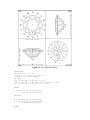
I suggest that you try to cut the Formée Cross Rectangle from the faceting diagram included in
the center of this manual. Once you can cut the design from the faceting diagram without
referring to the manual, you should be well prepared to cut from other published diagrams.
This completes the tutorial section of the manual. The next section is a reference manual that
describes each GemCad command in detail.
GemCad Reference Manual
The File Menu
The commands in this menu are to read and write disk files. GemCad deals with three types of
files. There are a pair of commands to read and write each type.
\command{Open (O)Open an existing project: read from a binary file
The Open (O) command is used to open an existing GemCad project file. Such a file is a binary
file saved previously with the Save (s) or Save as (S) command. GemCad will prompt you for
the name of the file. You may either type in the file name or just press the Enter key to use the
file picker. If you type in the file name, the file must be in the current directory, or a full or
relative path must be given (such as C:\CUTS\bril.gem or ..\QUARTZ\cut.gem). If there are
already facets cut, GemCad will ask permission to trash them before asking you for the file
name.
If you press the Enter key to use the file picker, GemCad will print a list of all of the files in the
current directory whose extension begins with "G." Subdirectories of the the current directory are
also shown. The list of subdirectories follows the list of files. You can distinguish the two
because directory names are followed by the \ backslash character. The directory ..\ is the
parent of the current directory.
One of the selections will be in reverse video and will have a small arrow to its left. You may use
the cursor keys or mouse to change which item is highlighted. You make a selection by pressing
the Enter key or a mouse button. If you select a file name, GemCad will try to open the file. If
you select a directory, GemCad will change to the new directory and display all of the files
matching the wildcard and all of the subdirectories in the new directory. (A wildcard is a pattern
that matches file names with certain characteristics.) There is also a special selection labeled
file spec. This allows you to change disk drives or the wildcard. The default drive is the drive
where you were when you started the program. The default wildcard *.G* matches any file name
whose extension starts with G. The ? character matches any one character, and the * matches an
arbitrary string of any length.
If you get into the file picker by accident, you can abort by pressing the Esc key or by selecting
empty space. This leaves the previous design intact. If you select a directory, it becomes the new
working directory.
\command{Save (s)Save the project as a binary file with the existing project name
The Save (s) command saves the design to disk as a binary file. If the project doesn't yet have a
name, GemCad will ask you for one. The name must be a valid DOS file name (eight or fewer
characters and an optional three character extension). If you don't provide an extension, GemCad
will automatically add .GEM to the end. If you don't want an extension, end the file name with a
period. Note that an extension beginning with G will make the file picker much easier to use.
The binary file is not readable by a human (you'll get hearts and clovers and all sorts of stuff if
you type it), but can be read quickly by GemCad. If the file you specify already exists, GemCad
will ask your permission to write over the file.
\command{Save (s)asSave the project as a binary file with a new project name
The Save as (S) command is similar to the Save (s) command, except that GemCad will prompt
you for a file name even if the project already has a name.
\command{New (N)Begin a new cut: TRASHES EXISTING PROJECT
The New (N) command is used to start over from scratch. This command deletes all facets.
GemCad will ask your permission to trash the existing design before it does so.
\command{Read (R)Read a project from a text file (such as made by the W command)
The Read (R) command reads the project from an ASCII text file such as made by the Write
text (W) command. If facets have been cut already, GemCad will ask you for permission to trash
them. This command can be slow if your machine doesn't have a a numeric co-processor. See the
Write text (W) command for details about the file format.
\command{Write text (W)Write the project as a text file
The Write text (W) command is used to write the project as an ASCII text file. GemCad will
prompt you for the name of the ASCII file. If you don't supply an extension, GemCad will add
.ASC to the name.
The Write text (W) command makes a file that is free format.
The ASCII files have two main uses. The first is to archive designs. The ASCII files have no
information about the vertices that make up the facets but only have information about the plane
of each facet. This means that the ASCII format is very compact. The other main use is to
extend--or subvert--the capabilities of GemCad. You can edit the resulting file with a text editor
or word processor, make changes, and then read it back in again with the Read (R) command.
You can use this technique to combine the pavilion and crown from separate files. The text file
has one line per tier of facets (unless there are more than 16 facets on one tier). With a text
editor, you can interchange lines to alter the cutting order.
A text editor is a program that allows you to make changes to text files. Text editors differ from
word processors in that they don't add any formatting information to the file. The EDLIN
program that comes with all versions of MS-DOS and the EDIT program that comes with DOS
5.0 are examples of text editors.
\command{L&S import (M)Import project from a Long & Steele format file
The L&S import (M) command reads a project from a file compatible with the programs written
by Robert Long and Norman Steele. Long and Steele have compiled a vast library of facet
designs, and GemCad can import these files directly. These files are text files and and have
names that typically end with the .P3D, .C3D, or .B3D extensions (for pavilion, crown, or both).
GemCad will prompt you for the name of file. If you just press the Enter key, GemCad will
bring up the file picker with the wildcard *.?3D. It will then scan the file and draw the stone on
the screen. Next, GemCad will prompt you for the symmetry of the stone just as in the
Symmetry (y) command.
GemCad will name each tier with a number in the same order as it appeared in the data file.
GemCad will make the I.D. position of the index gear at the top of the screen. If the stone is
longer than tall, you might have to scale it down with the Scale (X) to make it fit on the screen.
GemCad will print an error message if it encounters a facet with less than three sides. Any error
messages pertaining to the data file will begin with the line number in the data file at which the
error was encountered.
\command{L&S export (E)Export project to a Long & Steele format file
The L&S export (E) command makes a disk file compatible with the programs written by
Robert Long and Norman Steele. GemCad will prompt you for the name of the data file. The
name you enter should end with the .P3D, .C3D, or .B3D extension depending on whether your
design is just a pavilion, just a crown, or both pavilion and crown, respectively. If you don't
supply an extension, GemCad will add .B3D to the name.
There are several caveats to this translation process. The names of facets and the refractive index
will be lost, and the cutting order will be changed to make the crown first in the data file. The
orientation of the index gear will be changed to I.D. position at the top since that is the
orientation that the Long & Steele programs expect, but the direction of indexing will be
preserved. The z=0 plane will be made to coincide with the girdle line. This command might take
a long time on machines without numeric co-processors.
\command{Quit (Q)Quit GemCad
The Quit (Q) command is used to exit GemCad. You can also use the Esc key to quit. If you
have not saved the current design since making a change or addition, GemCad will ask you if it
is OK to quit anyway.
\command{Help (h)Print out help for next command instead of doing next command
The Help (h) command shows up in every menu. The Help (h) command prints out a one- or
two-line description of the next key that you press. The command corresponding to the key you
press is not executed, however.
\command{Print Screen (F12)Print what's on the screen
Function key F12 performs a screen dump. (If your keyboard does not have F12 or it doesn't
work, you may use Shift-F2 instead.) This command shows up in every menu. This print screen
function is completely independent of ordinary keyboard key labeled Print Scrn that invokes
the DOS print screen function so it is not necessary to load the GRAPHICS.COM program for the
F12 screen dump to work. GemCad supports IBM compatible dot-matrix printers and HewlettPackard LaserJet and DeskJet printers. See the configuration section of this manual to find out
how to specify the printer type.
\command{{Crosshairs (Spacebar)The spacebar draws or erases the dotted crosshairs across
the screen that intersect at the cursor.
The Crosshairs (Spacebar) command doesn't show up in any menu but is always available.
The crosshairs are convenient for lining things up vertically or horizontally. It also serves to tack
down the cursor if you use the mouse to pick items from the menu bar. If the command you plan
to use requires a point, you can tack down the cursor with the spacebar. Then when you select
the item from the menu bar, GemCad uses the location of the crosshairs and does not ask you to
set a point.
The Cut Facets Menu
The commands in this menu are for cutting new facets. The basic philosophy behind the cutting
of new facets is that GemCad will cut a tier of facets as soon as you have given it enough
information to specify one of the facets of a tier. (Facets on the same tier are cut at the same
angle and depth and have indexes related to each other through the symmetry of the stone.) The
section on the Symmetry (y) command gives more information on symmetry.
To determine the plane of a new facet, GemCad needs three pieces of information. There are
several different combinations of three pieces of information that will determine the plane of a
new facet:
One point, the index, and the angle
Two points and the index
Two points and an angle of 90°
Three points
The commands in this section allow you to give GemCad the angle or index of a facet to be cut.
GemCad will cut the facet immediately after you give it the last piece of information needed to
specify the facet. Sometimes you might not recall what information you have already specified.
The status box in the lower-left-hand corner of the screen shows a summary of the information
GemCad has for new facets. There are fields for the angle, index, and the number of points
entered so far. If you have not given GemCad any information about a new facet, GemCad will
display in the box the number of facets cut so far. To correct information in this field, the Draw
(d) command will redraw the stone and clear this field and cause any pending information about
new facets to be discarded.
\command{Angle (a)Set the angle of a new facet
GemCad will prompt you at the top of the screen for the bearing angle (in degrees) of the new
facet. Pressing the Enter key without entering an angle will abort the command. To correct an
incorrectly entered angle, simply repeat the command and enter the correct angle. The new angle
will replace the old.
\command{Jam angle (A)Set the angle of a new facet to be the same as that of the facet
surrounding the cursor
GemCad will search its database of facets and will find the facet surrounding the cursor. It will
then duplicate the angle as if you had entered it with the Angle (a) command. This can be quite
convenient when cutting step cuts with lot of facets cut at the same angle.
\command{Index (i)Set the index of a new facet
GemCad will prompt you for the index. Indexes may be fractional. Pressing the Enter key
without entering an index will abort the command. To correct an incorrectly entered angle,
simply repeat the command and enter the correct index. See the Index gear (g) command to find
out how to change the number of teeth on the index gear.
\command{Jam index (j)Set the index of a new facet to be the same as that of the facet
surrounding the cursor
GemCad will search its database of facets and will find the facet surrounding the cursor. It will
then duplicate the index as if you had entered it with the Index (i) command. This can be quite
convenient when cutting step cuts.
\command{Change (C)Change the facet surrounding by the cursor: next new facet will replace it
The Change (C) command is used to recut a tier of facets. It is similar in action to killing a tier
of facets with the Kill tier (K) command and then recutting the facet with two exceptions. First,
the index of the old facet is rounded off to the nearest integer, and entered just as if you had
entered it with the Index (i) command. (The index can then be changed to something else with
the Index (i) command.) Second, after the new tier of facets is cut, the cutting order remains the
same. (Killing a tier and cutting it again makes the new tier last in the cutting order.) The change
command disables several other commands. The auto-backup feature is turned off until the facets
are recut. Thus, the Undo (u) command will get you back to the point just before you executed
the change command regardless of any other changes to the stone. Only one tier of facets may be
changed at a time.
When a change is pending, an asterisk * will follow the index printed in the status box in the
lower-left-hand corner of your display. If you discard the index with the Draw (d) command,
GemCad will print the previous index in parentheses in the status box.
A problem can arise if you are cutting a design that has mixed symmetry, that is, some tiers of
facets are cut with one type of symmetry and others are cut with another type of symmetry.
GemCad does not keep track of which facets were cut with which symmetry setting. So, if you
use the Change (C) command to change a tier of facets, make sure you set the symmetry
properly for the changed tier.
\command{Draw (d)Draw the stone again, discard set points
The Draw (d) command is used to redraw the stone. As you cut new facets, GemCad only
redraws the facets that change. Sometimes in the process of redrawing, facet labels (see the
Name (n) command) and index labels can become partially erased. Redrawing the stone cleans
up the display. The Draw (d)g command also discards any pending information about facets to
be cut (angle, index, or points) and clears the status box in the lower-left-hand corner of the
screen. Thus, the Draw (d) command is also useful for correcting input errors.
The Draw (d) command also places dimension lines on the drawing of the stone. Each
dimension is given by a single character L, W, P, C, or T corresponding to the length, width,
pavilion, crown, and table. The relative values of these dimensions are listed with the List to
scrn (l) or List to file (L) commands. If a facet is changed or a new facet is cut that changes the
dimensions of the outline or table, the dimension lines will not be updated on the screen until the
Draw (d) command is executed.
\command{Zoom (z)Zoom in on the view surrounding the cursor or zoom back out again
The Zoom (z) command enlarges the view containing the cursor to fill the entire screen. The
zoom command toggles between two magnifications--the command doesn't do arbitrary
magnifications. If one view fills the screen, the zoom command will zoom back out to the four
views.
\command{Undo (u)Undo the last command that changed the stone
The Undo (u) command undoes the most recent change to the stone. Before each change to the
stone, GemCad saves the stone to disk in a file called gemcad.bak in the current directory. The
undo command simply reads in this file. Undo only undoes the previous command--repeated
undos have no effect. If you are running the program off a diskette, it must not be writeprotected. If you exit GemCad without saving the changes with the Save (s) command, if
(forbid!) the program crashes, you have a power failure, or if your toddler pushes the red button
on your tower system, you can get back to one step before the disaster by restarting the program
and pressing the Undo (u) key as the first command.
The Point Menu
The following commands are used to set points that will be used to cut a new tier of facets.
Whenever you enter one of the point commands, GemCad will draw cross-hairs intersecting at
the point you specified. (If the command picks a point relating to facets already cut, there might
be a slight delay while GemCad does the search.) GemCad will then print the coordinates of the
point and ask you if you want to use the point (as a piece of information for the cutting of a new
tier of facets) or discard it. Any answer beginning with y will be taken as yes, and anything else
(including just the Enter key) will be taken as a no. If you are using a mouse, the left button is
equivalent to a y, and the right button is equivalent to the Enter key. Thus, pressing the left and
then the right buttons is equivalent to a yes response, and pressing just the right button is
equivalent to a no response. The number of points set so far is displayed in the box in the lowerleft-hand corner of the screen. The following section describes each point command in detail.
\command{Meet pt (m)Set a point of a new facet at the existing meet point nearest cursor
GemCad will search its database of vertexes (meet points of three or more facets) and find the
one nearest the cursor in the "Manhattan sense" (sum of vertical and horizontal distances). The
cursor will "snap" to the meet point and GemCad will ask you if you want to use the point. Since
the exact meet point is determined by the equations for the planes of the facet, the point is set to
much finer precision than the resolution of the display you are using. When the cursor is visible,
the left mouse button is equivalent to the Meet pt (m) command.
\command{Pt on edge (e)Set a point of a new facet on the edge of an old facet nearest cursor
GemCad will search its database of edges of facets (the intersections of two facets) and find the
one nearest the cursor in a vertical or horizontal direction. The cursor will snap vertically or
horizontally on the screen to the nearest edge, and GemCad will print the x-y-z coordinates of the
point and ask you if you want to use the point. Only one of the x-y-z coordinates depends on the
screen resolution; the other two depend on the equations of the two facets that form the edge.
When the cursor is visible, the right mouse button is equivalent to the Pt on edge (e) command.
\command{Pt on facet (f)Set a point of a new facet on the interior of an old facet at cursor
GemCad will search its database of facets and determine which facet surrounds the cursor.
GemCad will then project the line of sight through the cursor and calculate the point of
intersection of this line and the facet. GemCad will print the x-y-z coordinates of the point and
ask you if you want to use the point. Since GemCad determines two of the three coordinates
from the cursor position, the resolution of this command is limited to that of your particular
display. Even with CGA resolution, however, this is seldom a serious limitation unless cutting
designs with small "floating" facets. When the cursor is visible, the center button on a threebutton mouse or pressing both buttons of a two-button mouse are equivalent to the Pt on facet
(f) command.
\command{Z-axis incpt (Z)Set a point where the plane of the facet surrounding the cursor
intersects the z (dop) axis.}
This command is useful if you are cutting several facets to a common centerpoint. It's also an
easy way to cut two facets at the same angle and mast height. Place the cursor inside an existing
facet. If the facet encloses the centerpoint of the Top View, GemCad will pick this point of
intersection. Otherwise, GemCad will project the plane of the facet and compute the point of
intersection with the z (dop) axis. GemCad will ask you if you want to use the point.
\command{Pierce zero (p)Set a point of a new facet where the cursor pierces the zero plane
This is the probably the most difficult of the point commands to understand, but it is seldomly
used. Each of the four views shows a projection of the stone onto one of the three coordinate
planes. The Top View is the projection of the stone onto the x-y plane. (The z axis is the axis of
rotation of the dop.) In the Top View, the p command will set the x and y coordinates to those of
the cursor, and the z coordinate will be set to zero. In the End View, the Pierce zero (p)
command sets the x and z coordinates, and the y coordinate is zeroed. In the Side View, the
Pierce zero (p) command sets the y and z coordinates, and the x coordinate is zeroed. As with
the other point commands, GemCad will draw cross-hairs, print the x-y-z coordinates of the point
and ask you if you want to use the point.
The Pierce zero (p) command is useful for making a preform from a sketch. One method is to
sketch or photocopy a sketch of the stone on a transparency and tape it to your screen. Zoom in
on the Top View (with the Zoom (z) command) and center the dop axis on the dot at the center
of the Top View. The sketch should have the girdle outline divided into line segments. Enter an
angle of 90 degrees and set two consecutive points on the girdle outline with the Pierce zero (p)
command. GemCad will cut the resulting facet. If you go all the way around the girdle outline in
this fashion, you will cut a preform of girdle facets at 90° with the same outline as your drawing.
The indexes of the resulting facets will not be whole numbers, however. You can use the
Change (C) command to change the index of each facet to a whole number. You then cut facets
around the stone to a temporary center point, working in the Side and End Views. These facets
must be at the same indexes as the girdle outline facets to make a level girdle. (You can use the
Jam index (j) command to duplicate the index of the facet surrounding the cursor.) This makes
what is commonly referred to as a C.A.M. (Centerpoint Angle Method) Preform.
\command{Query user (q)Query user for x, y, and z coordinates of a point of a new facet
If you know the (x, y, z) coordinates of a point on a new facet, the Query user (q) command
allows you to enter the numerical values of the coordinates directly from the keyboard. GemCad
will prompt you for each of the three values in turn. When cutting a C.A.M. preform, it's
sometimes best to start with the point (0, 0, 1).
For convenience, the Draw (d), Zoom (z), and Undo (u) commands are also found in the Point
Menu. They are described above in the section on the Cut Facets Menu.
The Edit Menu
Most of the commands in the Cut Menu change the stone in some way.
\command{Xfer (x)Transfer the stone
The Xfer (x) command is used to transfer the stone. The stone will be turned upside-down. What
was in the Top View will be in the Bottom View. You will find it easiest to do most cutting in
the Top View. This is because the Top View aligns horizontally with the Side View and
vertically with the End View.
\command{Kill facet (k)Kill the facet surrounding the cursor
The Kill facet (k) command deletes a single facet. The facet is erased and the facets it used to
share an edge with are recomputed and redrawn. This can be a slow process on machines without
numeric co-processors.
\command{Kill tier (K)Kill a tier of facets, one of which surrounds cursor
The Kill tier (K) command kills an entire tier of facets. The facets are erased, and each facet that
shares an edge with one of the killed facets is recomputed and redrawn. This command can be
quite slow on machines without numeric co-processors.
\command{Center (c)Center the current view about the cursor
The Center (c) command is used to center the stone about the cursor in the view containing the
cursor. Let's consider the End View. The End View shows a projection of the stone in the x-z
plane, with x increasing to the right and z increasing up the screen. Let's say that your stone
positioned too far up in the End View and you want to move it down. Move the cursor inside the
stone to its approximate center by eye and press the Center (c) key. (Only the vertical position of
the cursor is important.) The cursor should be above the dot at the center of the End View.
GemCad will ask which coordinate you want centered. Enter z. GemCad will redraw the stone,
sliding the stone down so that the position you specified is at the center of the End View.
GemCad will slide the stone down the vertical distance from the cursor to the center dot.
The center command can also be used to shift the center of the dop axis by centering the x or y
coordinate in the Top or Bottom Views. This is useful for pears and other stones with 1-fold
symmetry.
You will get an error message if the coordinate you specify has its axis perpendicular to the view
containing the cursor, or if the stone is already centered about the cursor. For instance, if you tell
GemCad to center in the z direction while the cursor is in the Top View, GemCad will tell you
that you are in the wrong view to center that coordinate since the z axis is perpendicular to the
Top View.
When GemCad cuts a facet it conceptually cuts the stone in two at the plane of the facet and
discards one part of the stone and keeps the other. How does GemCad know which part to keep
and which part to discard? The rule is that GemCad keeps the part of the stone containing the
point (0, 0, 0) and discards the other part. The (0, 0, 0) point is marked by a dot at the center of
each view. If you are cutting a skinny stone such as a marquise and you are having problems
with GemCad cutting a facet in the wrong place, cutting away most of your stone, GemCad
could be cutting off the part you really want it to keep. The solution to this problem is to use the
center command to slide it up or down so that the center dot is contained in the part you want
GemCad to keep.
\command{Rotate/Tilt (r)Rotate/tilt the stone; will prompt for what fraction of a revolution
The Rotate/Tilt (r) command will rotate the stone clockwise in the view containing the cursor.
Thus, if the cursor is in the Side or End View, the stone will be tilted. If the cursor is in the Top
or Bottom View, the stone will be rotated about the axis of the dop. GemCad will prompt you for
the numerator and denominator of the fraction of a revolution you want to rotate or tilt the stone.
Thus, if you want to rotate the stone, say, 10 degrees, enter 10 for the numerator and 360 for the
denominator. To rotate the stone one-half revolution, enter 1 for the numerator and 2 for the
denominator.
\command{Tan ratio (T)Tangent ratio scale top or bottom keying off of facet surrounding
cursor
The Tan ratio (T) command is used to change all of the angles of one side of the stone to adapt
a design to a different index of refraction. GemCad will search its database of facets to find the
facet surrounding the cursor. The angle of the facet will be printed and GemCad will prompt you
for the new angle of this facet. The entire side of the stone containing the selected facet will be
scaled by the ratio of the tangents of the two angles. If the stone does not have a level girdle, the
junction of the pavilion and crown might be distorted. If this is the case, the Playback (P)
command can be used to recompute all facet edges and make the facets meet properly.
\command{Waytwace (w)Trace a light ray from cursor into stone and back out of stone
The Waytwace (w) command twaces a single way--ahem!--traces a single ray of light through
the stone. This is the only command in the Cut Menu that does not change the stone. It was
placed in the Cut Menu to be close to the Tan ratio (T) command. The light ray will enter the
screen perpendicular to the cursor, bounce around in the stone and then exit the stone. The ray is
shown in all four views. This is a single-shot sort of a deal--one ray of light per command. A
separate program (see the READ.ME file on your GemCad distribution diskette) is used to make
ray-traced images of your design. You can note the leaky spots in the design and use the
Waytwace (w) command to find out the cause of the leak. The Refr index (I) command is used
to change the index of refraction. Rays are drawn in complement mode--shooting an identical ray
a second time will erase it. A good ray should enter and exit crown facets.
\command{Scale (X)Scale the stone: change angles, shrink, enlarge, stretch, etc.
The Scale (X) command is used to stretch or shrink the stone in one direction. The command has
several variations. GemCad will ask you
Code (all, top, bot, x, y, z)?
The scale command has several uses. If your response begins with an a or A, GemCad will scale
the entire stone. GemCad will prompt you for the numerator and denominator of the factor by
which the stone is to be multiplied. The stone is enlarged if the numerator is larger than the
denominator or shrunk if the denominator is larger than the numerator. No angles or indexes are
changed.
A response beginning with x or X will stretch or shrink the stone horizontally in the Top View.
You can use this, for instance, to turn a round design into an elliptical one. A response beginning
with y or Y will stretch the stone vertically in the Top View. In either case, GemCad will prompt
you for the numerator and denominator of the scale factor. Angles and indexes will be changed.
Indexes will probably not be whole numbers; the Change (C) command may be used on each
tier to make its index a whole number. Facets that used to be at the same index and depth before
the scale command might be at different angles and depths after scaling.
The x or y options will also cause GemCad to re-tier the stone. This process might take a while
on slower machines. The re-tier operation groups together facets cut at the same bearing angle
and depth regardless of their relationship through symmetry. To force the re-tier operation
without otherwise changing the stone, scale the stone in the x (or y) direction by a factor of 1
over 1. After the stone is re-tiered, GemCad will prompt you for the new symmetry of the stone
just as if you had entered the Symmetry (y) command. This new symmetry applies only to facets
yet to be cut.
If your response begins with a t or T, GemCad will scale the side of the stone currently in the
Top View, be it the pavilion or crown. If your answer begins with a b or B, GemCad will scale
the side of the stone in the Bottom View. A response beginning with z or Z will stretch or shrink
the stone vertically in the End View thus scaling both the pavilion and crown by the same factor.
All three variations perform Tangent Ratio scaling. In most cases, however, the Tan ratio (T)
command is easier to use. GemCad will prompt you for an old angle and a new angle. GemCad
will scale the stone such that a facet which was formerly at the old angle will be at the new
angle. This will change the angles but not the indexes. If your stone does not have a level girdle,
the girdle line might be distorted somewhat after the stone is scaled. This can be fixed with the
Playback (P) command.
The Undo (u) command is also duplicated in the Cut Menu. It is described in the section on the
Cut Facets Menu above.
The Parameter Menu
The commands in the Parameter Menu are used to set parameters or switches.
\command{Index gear (g)Change the index gear
The Index gear (g) command is used to change the number of teeth of the index gear. GemCad
defaults to a 64 tooth gear when first run. After you press the Index gear (g) key, GemCad will
prompt you to enter the number of teeth on the index gear. GemCad has provision for clockwise
and counter-clockwise orientations. Gears with positive numbers of teeth increase counterclockwise, and gears with negative numbers of teeth increase clockwise. Next GemCad will ask
you for the offset. This is the index which will appear at the bottom of the circle of numbers in
the Top View. An offset of zero causes the I.D. position to be at the bottom, and an offset of half
the number of teeth of the gear cause the I.D. position to appear at the top. Pressing Enter
without entering an offset also makes the I.D. position to appear at the bottom. The number of
teeth must be a whole number, but the offset may be fractional.
\command{Symmetry (y)Change the degree of radial symmetry and whether mirror-image
symmetry
The Symmetry (y) command allows you to tell GemCad how many facets make up a tier and are
cut at the same angle and cutting depth (mast height). GemCad will prompt you for the degree of
radial symmetry and whether or not the stone has mirror-image symmetry. The stone and index
gear will then be redrawn.
The degree of radial symmetry is the minimum number of facets which will be cut at once.
Facets at an angle of zero are the only exception to this rule since they can be cut at any index. If
the stone has mirror-image symmetry, twice as many facets as the degree of radial symmetry can
be cut at once. The exceptions are facets that are mirrored by themselves--facets whose indexes
are integer multiples of the number of teeth on the gear divided by twice the degree of radial
symmetry. Consider an example. A standard round brilliant has eight-fold radial and mirrorimage symmetry. If enough information is given to cut one of the break facets, GemCad will cut
all sixteen break facets at once. It knows, however, to cut only eight mains and stars because
these facets are mirrored by themselves.
What about other symmetries? If the stone is put at the center of a pie, the degree of radial
symmetry is the maximum number of identical wedge-shaped pieces into which the stone can be
cut. If it can't be cut into at least two pieces, the degree of radial symmetry is one. If each of the
identical pieces has bilateral symmetry (if it can be folded in two along its centerline) then the
stone also has mirror-image symmetry. Consider some examples. A snowflake has six-fold,
mirror-image symmetry. It can be cut into six identical pieces, and each of the six pieces can be
folded in two. A pear-shaped stone has no radial symmetry, but has mirror-image symmetry so it
has one-fold, mirror-image symmetry. A stone whose outline is a parallelogram has two-fold
radial symmetry but does not have mirror-image symmetry. An emerald cut has two-fold, mirrorimage symmetry. Most triangular stones have three-fold, mirror-image symmetry.
Eight-fold, mirror-image is the default when GemCad is first run. The default can be changed
when configuring GemCad. The symmetry of the stone is saved when the project is saved with
the Save (s) or Save as (S) commands. You can change the symmetry in the middle of a design.
For instance, you can cut a pavilion with one type of symmetry and a crown with another. Only
the current symmetry is listed by the List to scrn (l) or List to file (L) commands.
If the number of teeth on the index gear is not an integer multiple of the degree of radial
symmetry, GemCad will round off indexes to the nearest tooth. This allows you, for instance, to
cut a seven-sided stone on a 64 index gear.
\command{Refr index (I)Index of refraction: change it and print the critical angle
The Refr index (I) command is used to change the index of refraction for the Waytwace (w)
command. GemCad will tell you the old index of refraction and will prompt you for the new one.
GemCad will then print out the critical angle in the upper-left-hand corner of the display. A null
response (just the Enter key) causes the R.I. to remain unchanged, but the critical angle is
displayed again. When you save a design GemCad saves the R.I. with the facet data. When
GemCad is first run, the refractive index is set to 1.54 for quartz. This default can be changed
when you configure GemCad.
\command{Time-Lapse (t)Turn time-lapse on/off
The Time-Lapse (t) command affects how the stone is redrawn as facets are cut. If time-lapse is
on, only facets changed by the addition of a new tier of facets are redrawn. If time-lapse is off,
the entire stone will be redrawn after the tier of facets is added.
The Utility Menu
\command{Blink facet (b)Recompute the facet surrounding the cursor
The Blink facet (b) command erases the facet surrounding the facet, recomputes it, and then
redraws (blinks) it. This is the quickest way to find out the angle and index of a facet: they are
printed in a box at the upper-left-hand corner of the screen.
\command{Blink tier (B)Recompute a tier of facets, one of which surrounds cursor
The Blink tier (B) command recomputes an entire tier of facets. GemCad searches its database
of facets and finds the one surrounding the cursor. All facets belonging to the same tier as the
specified facet are recomputed and redrawn (blinked).
\command{Meas vector (v)Display distance, angle and index of line joining last two points
A vector is a quantity with magnitude and direction. The Meas vector (v) command is used as a
measuring stick. It gives the length and direction of the line joining two points. To use the Meas
vector (v) command, pick two points, typically with the Meet pt (m) command (or the left
mouse button). When GemCad asks you to use the points, enter "n" or just press Enter. Then
press the Meas vector (v) key. GemCad will print the distance between the two points projected
along each axis and also give the true length of the line joining the two points. Next, GemCad
will print the bearing angle and index of the line joining the two points. One use for this feature
is to figure out the minimum angle needed to cut off an edge.
\command{Set vector (V)Set units for Meas vector (v) command
The Set vector (V) command is used to set the length of the measuring stick used for the Meas
vector (v) command. The main use of this feature is to allow you to measure the ratio of two
lengths without having to divide the numbers yourself. Let's say you want to measure the length
of a feature on a design as a fraction of the width of the design. First, pick two points on opposite
sides of the stone with the Meet pt (m) key. (But tell GemCad not to use the points for a new
facet.) Next, press the Set vector (V) key. GemCad will print the length and direction of the line
joining the points as in the Meas vector (v) command. GemCad will then ask you along which
axis you want the distance to be set and how many units long you want this segment to be. For
instance, if you want your measuring stick set such that the width of the stone is one unit and
your stone is longer than it is wide, pick two points opposite one another at the widest point of
the stone. Press the Set vector (V) key. Press Enter twice to acknowledge the length and
direction in the old units. GemCad will then ask you along which axis the length is measured that
to you wish to set. Next it asks how many new units long to set this distance. In most cases, you
will probably want to set this distance as one unit long.
\command{Playback (P)Recut the stone
The Playback (P) command is used to recut the stone. The stone is shown at every stage as it is
recut. GemCad will ask you if you want it to wait for you to press a key between facets. If your
answer begins with a "y" GemCad will cut facets one at a time, waiting for you to press any key
or mouse button. Otherwise, GemCad will ask you how long to wait between facets. A value of
0.5 seconds slows things down enough to see each facet as it is cut. The default is not to wait at
all. Since the playback can take a long time on machines without numeric co-processors,
pressing the Esc key will abort the playback. The overall effect of the playback is to show an
animation of the stone as it is cut. The playback command also recomputes the stone and can
sometimes improve the appearance of meet points or edges. You should use the Playback (P)
command after the Tan ratio (T) command to improve the accuracy of the computed meet
points.
\command{Demo (D)Recut the stone repeatedly to demonstrate GemCad
The Demo (D) command repeatedly executes the Playback (P) command in an endless loop. As
with the Playback (P) command GemCad will ask you how long to pause between facets. After
the stone is recut, GemCad will pause for five seconds. The demo will continue until you
interrupt it with the Esc key.
\command{Constr line (-)First time starts at cursor, second time draws to cursor
The first time you press the Constr line (-) key, GemCad does nothing except to save the last
location of the dotted cross-hairs (or the cursor if the cross-hairs are not on). The second time
you press the minus key, GemCad will draw a dotted construction line from the saved point to
the new location of the crosshairs (or cursor). You can get crosshairs at the cursor by pressing the
space bar.
\command{Dos (!)Execute a DOS command
The Dos (!) command allows you to executes one or more DOS commands. GemCad will
prompt you with DOS> at the top of the screen, and you may enter a one-line DOS command
which will be executed in a text screen. After DOS executes the command, GemCad will ask you
to press any key to redraw the stone.
If you want to escape to a DOS session to execute several commands and then return to
GemCad, simply press the Enterg at GemCad's DOS> prompt. This will start new DOS session in
a text screen. When you finish the DOS session, you must use the EXIT command of DOS to
return to GemCad.
The Diagram Menu
\command{List to scrn (l)List cutting schedule of angles and indexes to screen
The List to scrn (l) command lists the cutting schedule to the screen. Facets are listed in the
order they were cut. GemCad will wait for you to press any key or mouse button at the bottom of
each full screen of text. If you have used the Heading (H) command to enter the design name
and author, the listing will begin with the heading. The relative length, width, table length, and
pavilion and crown heights are shown next. These dimensions are those called out on the
diagram. The facets visible in the Top View are labeled "Crown," and those in the Bottom View
are called "Pavilion."
Each tier of facets is given by one or more lines in the listing. The tier begins with its name (see
the Name (n) command) if it has one. Next comes the bearing angle in degrees. Next come the
list of index positions separated by hyphens. This might take several lines. The rightmost column
contains the cutting instructions if you have entered them with the Gloss (inst) (G) command.
If you have used the Footnote (F) command to enter a footnote, the note will be at the bottom of
the listing.
\command{List to file (L)List cutting schedule of angles and indexes to printer or file
The List to file (L) command lists the cutting schedule to a file or printer. The format is
basically the same as with the List to scrn (l) command. GemCad will prompt you for the name
of the file, which must be a valid DOS file name. If the file exists, GemCad will ask for your
permission to write over the file. Entering the file name PRN, or a port name such as LPT1 or
COM1, whichever is appropriate on your system, will list the cutting schedule to the printer. The
file that is written is a flat ASCII text file. You may use your favorite text editor or word
processor to annotate the cutting instructions and print them out.
The format of the List to file (L) command is somewhat different than that of the List to scrn (l)
command. The heading and dimensions are set off in an indented block by themselves. The
cutting instructions follow. When you configure GemCad, you can specify the margins, the
height of the header and how much the header is indented.
\command{Name (n)Name or label the facet surrounding the cursor
The Name (n) command searches the database of facets to find the facet surrounding the cursor.
GemCad then prompts you for the name of the facet and labels the facet with the name. Names
can be up to three characters, although only one or two character names will fit in any but the
largest facets. The names will also appear in the cutting schedule (made by the List to scrn (l)
and List to file (L) commands). Naming a facet that already has a name renames the facet, but a
null name (just the Enter key) will erase the name. If two facets in the same tier of facets (same
angle and depth) are named different names, only one name will appear in the cutting schedule.
\command{Gloss (inst) (G)Provide cutting instructions for facet surrounding the cursor
A gloss is a brief explanation or annotation. The Gloss (inst) (G) command allows you to
provide brief cutting instructions for a tier of facets, one of which surrounds the cursor. The
cutting instructions will be printed on the listing made with the List to scrn (l) or List to file (L)
commands to the right of the indexes that make up the tier.
\command{Heading (H)Enter a heading including title, designer, date, etc.
The Heading (H) command allows you to enter up to four lines of text that show up at the top of
the listing with the List to scrn (l) or List to file (L) commands. If you have already used the
Heading (H) command to enter a heading, subsequent times allow you to edit the heading. You
may use the Insert, Delete, End, and Home keys. The purpose of this text is to allow you to
enter the name of the design, the designer, the date and reference.
\command{Footnote (F)Enter a footnote
The Footnote (F) command allows you to enter up to four lines of text that are printed at the
bottom of the listing made with the List to scrn (l) or List to file (L) commands. If you have
already used the Footnote (F) command to enter a footnote, subsequent times allow you to edit
the footnote. You may use the Insert, Delete, End, and Home keys.
Configuring GemCad
When you first run GemCad it will print out a Copyright notice, tell you where it got its current
configuration, and ask you press c to configure or any other key to start the program. If you press
the c or C key, GemCad will enter its configuration mode. This allows you to change the default
parameters such as index gear and symmetry. It also allows you to specify parameters relating to
your printer. This configuration is stored in a file named GEMCAD.CFG in the current working
directory.
When GemCad is first run, it tries first to find a file called GEMCAD.CFG in the current working
directory. If it cannot find such a file, it looks in the same directory in which the GEMCAD.EXE
resides for a file named GEMCAD.CFG. If it can't find either configuration file, it just uses the
defaults built into GEMCAD.EXE. You can therefore make a generic configuration in the same
directory where GemCad resides and then make different directories for special situations.
The questions about margins and headers pertain to the format of the listing produced with the
List to file (L) command. The List to file (L) command is set up to make a listing that can be
printed with the diagram produced with the GemPlot, GemJet, or GemDot programs. These
programs produce publication-quality diagrams on various printers from your GemCad files.
They do not print the cutting instructions, however. Since the margins, character pitch and line
spacing vary with the type of printer, GemCad allows you to adjust the print position of various
parts of the diagram.
The first part of the listing is the header. It contains the heading as entered with the Heading (H)
command, a tally of the number of facets, some parameters, and the dimensions of the stone. The
header is indented more than the cutting instructions that follow. Blank lines follow the header so
that the cutting instructions always begin on the distance from the top of the page regardless of
the length of the header.
The four parameters that you can set are:
Top margin: The number of blank lines from the top of the listing to the first line of the
header.
Left margin: The number of spaces before each line of the cutting instructions.
Top header: The maximum number of lines in the header, or the number of lines from the top
margin to the beginning of the cutting instructions.
Left header: The extra number of spaces that the header is indented.
If you set these four parameters to zero, the format of the List to file (L) command will be
identical to the format of the List to scrn (l) command.
The default choices for these were tested with the GemDot prorgram with Epson LQ510 printer
using its Courier typeface. You will have to experiment with the margins to adapt the listing
format to your printer.
GemCad can print a copy of the screen on HP DeskJet, LaserJet, or IBM or Epson printers. All
of the HP printers need the information in one format and the IBM and Epson printers need it in
another. If you select the IBM compatible printer, GemCad will ask you for the aspect ratio of
your printer. For most 9-pin printers, enter 1.2. For most 24-pin printers, enter 1. GemCad will
print only the square plotting area of the screen. Make a test plot with one of the suggested
values above and measure the square to make sure its width is the same as its height. If not,
reconfigure GemCad and multiply the aspect ratio by the ratio of the width to the height. If you
select the HP compatible printer, the aspect ratio is ignored since all of the HP printers have
square pixels.
Error Recovery
What if you press a key that executes a command that you didn't intend to? Let's say you pressed
the Angle (a) key by mistake. GemCad will ask you to enter the angle. If you just press the
Enter key or the right mouse button, GemCad will abort the command.
What if you enter an angle incorrectly and don't realize it until after you have pressed the Enter
key? Just press the Angle (a) key again, this time entering the angle correctly.
What if you enter an angle when you meant to enter an index? If you redraw the screen with the
Draw (d) key, GemCad will discard all data pertaining to new facets and will clear the status box
in the lower-left-hand corner of the screen.
What if you accidently gave GemCad enough information to cut a facet that you really didn't
want to cut? You can wait until GemCad finishes and then use the Undo (u) key. What if you tell
GemCad to cut a facet that starts hacking away at your stone? If a facet is cut off, GemCad will
tell you so in an error message telling how may facets were cut off. You must then press any key
to acknowledge the error message. You may then use the Undo (u) key to uncut the facet. If
GemCad seems to be taking a long time to compute the new facets, you may interrupt it by
pressing the Escape key. This immediately does an undo. The Escape key will also interrupt the
Kill facet (k) or Kill tier (K) key commands.
If a new facet misses the stone entirely, GemCad will sometimes draw a "stone within a stone."
The way out of this is with the Undo (u) key. What if you've already changed the stone so that
the undo key doesn't get rid of the "phantom" facets? You can position the cursor inside the
phantom facet, press the Blink facet (b) key and make sure only the phantom facet blinks, and
then kill the facet (or tier) with the Kill facet (k) or Kill tier (K) keys. It might be necessary to
move to a different view or to rotate the stone with the Rotate/Tilt (r) key to specify the
phantom facet unambiguously. Again, before using the Kill facet (k) or Kill tier (K) keys to kill
a phantom facet, check first with the Blink facet (b) key to make sure GemCad will kill the facet
you want it to kill.
Last resort: If things are totally hopeless, if your two-year-old has pressed the red reset button, or
if there has been a power failure, there is still hope. Restart your computer, change directories to
where you were when you last ran GemCad, run GemCad and execute the Undo (u) key. This
will read in the file GEMCAD.BAK and get you back to one step before the catastrophe. It is
important to do this before reading in any other file or cutting any new facets since any
command that changes the stone will overwrite the file.
Using GemCad with a Mouse
Versions 2.0 and later of GemCad support a Microsoft or compatible mouse (most are). The
interface program supplied with your mouse (such as MOUSE.COM) must be loaded before running
GemCad. This is most commonly done in the AUTOEXEC.BAT file, but may be done anytime at
the DOS prompt. (GemCad does not work with device-drivers such as MOUSE.SYS that are loaded
in the CONFIG.SYS file.)
You can use the mouse to position the cursor and to execute commands. If you move the mouse
pointer into the menu label area at the left of the screen, you can highlight a particular menu
choice. Pressing any of the mouse buttons while a choice is highlighted will select that choice.
This is equivalent to pressing the corresponding function key with one exception: if the
command you selected refers to a point, GemCad will print "Set a point" in the upper-left-hand
corner of the screen. The selected menu choice will then remain lit until you move the cursor into
the drawing area, position the cursor at the point you want and then press a mouse button. The
command will then be executed just as if you had pressed the corresponding function key while
the cursor was at the point you set.
When the cursor is positioned in the drawing area and a menu choice is not highlighted, the
mouse buttons are mapped to commands in the Point Menu. The left button is mapped to the
Meet pt (m) command, and the right button is mapped to the Pt on edge (e) command. If you
have a three-button mouse, the center button is mapped to the f (point on facet) command. (On a
two-button mouse, pressing both buttons simultaneously will also perform the Pt on facet (f)
command.)
When GemCad is prompting you for input at the top of the screen, the left mouse button is
mapped to the y key and the right button is mapped to the Enter key. Thus, to answer yes to a
yes or no question, press the left and then right mouse buttons. To answer no, enter a null
response by pressing just the right mouse button. The center button (if present) is mapped to a
backspace.
Consider an example. To set a meet point and use it to add a new facet, move the mouse near the
meet point, press the left button (mapped to the Meet pt (m) command). GemCad will then ask
you if you want to use the point. Press the left button (mapped to y) and then the right button
(mapped to Enter). You can set meet points, points on edges, and points on facets without
touching the keyboard.
The cursor keys work exactly the same way with a mouse as they do without. They are
convenient for moving the cursor vertically or horizontally from another point on the screen.
There are two environment variables that pertain to the mouse when used with GemCad. If you
mouse seems to move two or more pixels in one axis or if the cursor keys don't seem to work in
one of the four directions, read further. If you type "SET MXDIV=2" at the DOS prompt prior to
running GemCad, the program will divide the X mouse ticks by two. This makes the mouse half
as sensitive horizontally as before. Similarly the variable MYDIV divides the vertical mouse ticks.
You can put one or both of these commands in your AUTOEXEC.BAT file. If you get a DOS error
message like "Out of environment space," you must place the SET commands near the top of
your AUTOEXEC.BAT file. Most of the newer mouse drivers have adjustable resolution, and you
should fix the problem there.