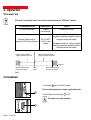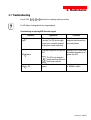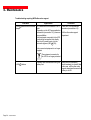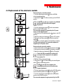
1
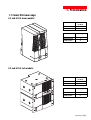
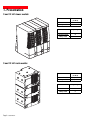
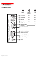
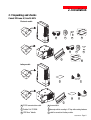
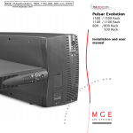
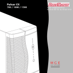
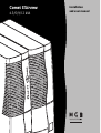
Comet EXtreme
4.5/6/9/12 kVA
installation
and user manual
51033212EN/AA
- Page 1
Introduction
Thank you for selecting an MGE UPS SYSTEMS product to protect your electrical equipment.
The Comet EXtreme range has been designed with the utmost care. We recommend that you take
the time to read this manual to take full advantage of the many features of your UPS.
MGE UPS SYSTEMS pays great attention to the environmental impact of its products.
Measures that have made Comet EXtreme a reference in environmental protection include:
◗ production in an ISO 14001 certified factory;
◗ recycling of Comet EXtreme at the end of its service life.
To discover the entire range of MGE UPS SYSTEMS products and the options available
for the Comet EXtreme range, we invite you to visit our web site at www.mgeups.com
or contact your MGE UPS SYSTEMS representative.
Page 2 - 51033212EN/AA
Safety
Safety rules
Safety of persons
A UPS has its own internal power source (the battery). Consequently, the output terminals may be energized
even if the UPS is disconnected from the AC-power source.
Dangerous voltage levels are present within the UPS. It should be opened exclusively by qualified
service personnel.
The UPS must be properly earthed.
The battery supplied with the UPS contains small amounts of toxic materials. To avoid accidents,
the directives listed below must be observed.
◗ Never operate the UPS if the ambient temperature and relative humidity are higher than the levels
specified in the documentation.
◗ Never burn the battery (risk of explosion).
◗ Do not attempt to open the battery (the electrolyte is dangerous for the eyes and skin).
◗ Comply with all applicable regulations for the disposal of the battery.
Product safety
The UPSs connection to the AC-power source must be protected by a circuit breaker
that is easily accessible.
The UPS can be disconnected from the AC-power source by opening the circuit breaker.
◗ Never install the UPS near liquids or in an excessively damp environment.
◗ Never let a liquid or foreign body penetrate inside the UPS.
◗ Never block the ventilation grates on the front or back of the UPS.
◗ Never expose the UPS to direct sunlight or a source of heat.
Special precautions
The UPS connection instructions contained in this manual must be followed in the indicated order.
Check that the indications on the rating plate correspond to your AC-power system and to the actual
electrical consumption of all the equipment to be connected to the UPS.
If the UPS is positioned flat, check that not more than five modules are stacked on top of each other.
If the UPS must be stored prior to installation, storage must be in a dry place.
The admissible storage temperature range is -40° C to +50° C.
If the UPS remains de-energized for a long period, we recommend that you energize the UPS
for a period of 24 hours, at least once every month.
This charges the battery, thus avoiding possible irreversible damage.
51033212EN/AA
- Page 3
Foreword
Using this document
Information may be found primarily by consulting:
◗ the contents;
◗ the index.
Pictograms
Important instructions that must always be followed.
Information, advice, help.
Visual indication.
Action.
Audio indication.
In the illustrations on the following pages, the symbols below are used:
LED off.
LED on.
LED flashing.
Page 4 - 51033212EN/AA
Contents
1.
2.
Presentation
1.1
Comet EXtreme range ................................................................................................................ 7
1.2
Back ............................................................................................................................................. 9
1.3
Control panel ............................................................................................................................... 10
Installation
2.1
Unpacking and checks ............................................................................................................... 11
"Tower" and "rack" model: 4,5 and 6 kVA ..................................................................................... 11
"Tower" and "rack" model: 9 and 12 kVA ...................................................................................... 12
3.
2.2
Installation (rack version) .......................................................................................................... 13
2.3
Battery-module connections ..................................................................................................... 14
2.4
Connection to the RS 232 communications port (optional) ................................................... 15
2.5
Installation of the communications-card option ...................................................................... 15
2.6
Connection to the connection modules ................................................................................... 16
Operation
3.1
Operating mode .......................................................................................................................... 17
ON-LINE mode ............................................................................................................................. 17
ECO mode .................................................................................................................................... 17
3.2
Start-up ........................................................................................................................................ 18
3.3
Bargraph indications .................................................................................................................. 18
3.4
Failure of AC input power and operation on battery power .................................................... 19
Transfer to battery power .............................................................................................................. 19
Threshold for the low-battery shutdown warning .......................................................................... 19
End of backup time ....................................................................................................................... 19
Sleep mode ................................................................................................................................... 19
Return of AC input power .............................................................................................................. 19
51033212EN/AA
- Page 5
Contents
3.5
Personalization ........................................................................................................................... 20
Function ........................................................................................................................................ 20
"ON / OFF conditions" tab ............................................................................................................. 20
"Battery" tab .................................................................................................................................. 21
"Output" tab ................................................................................................................................... 21
"By-pass" tab ................................................................................................................................ 21
"ECO mode" tab ............................................................................................................................ 22
3.6
4.
5.
6.
Page 6 - 51033212EN/AA
Shutdown ..................................................................................................................................... 22
Maintenance
4.1
Troubleshooting .......................................................................................................................... 23
4.2
Replacement of the electronic module ..................................................................................... 25
Environment ..................................................................................................................................... 26
Appendices
6.1
Glossary ....................................................................................................................................... 27
6.2
Index ............................................................................................................................................. 29
1. Presentation
1.1 Comet EXtreme range
4,5 and 6 kVA tower models:
Dimensions in mm
(H x W x D)
Electronic module
443 x 173 x 465
Battery module
443 x 173 x 465
Weight in kg
Electronic module
14
Battery module
48
4,5 and 6 kVA rack models:
Dimensions in mm
(H x W x D)
Electronic module
177 (4U) x 483 x 462
Battery module
177 (4U) x 483 x 462
Weight in kg
Electronic module
18
Battery module
51
51033212EN/AA
- Page 7
1. Presentation
9 and 12 kVA tower models:
Dimensions in mm
(H x W x D)
Electronic module
443 x 216 x 465
Battery module
443 x 173 x 465
Weight in kg
Electronic module
22
Battery module
48
9 and 12 kVA rack models:
Dimensions in mm
(H x W x D)
Electronic module
221 (5U) x 483 x 462
Battery module
177 (4U) x 483 x 462
Weight in kg
Page 8 - 51033212EN/AA
Electronic module
27
Battery module
51
1. Presentation
1.2 Back
Comet EXtreme 4,5 and 6 kVA:
1
RS232 communications port.
2
battery circuit breaker.
3
communications-card option.
4
EXB battery module connector.
5
connector for battery extension modules.
6
rating plate.
7
manual by-pass switch.
8
connection module.
9
output terminal block.
10 input terminal block.
Comet EXtreme 9 and 12 kVA:
4
51033212EN/AA
- Page 9
1. Presentation
1.3 Control panel
Page 10 - 51033212EN/AA
Alarms
% battery
␣ ␣ remaining
% load
11
UPS overload
100%
100%
12
electronics fault
80%
80%
13
battery fault
50%
50%
14
ambient temp.
> 40°C
20%
20%
15
hold down to display
percent load.
16
lamp test or buzzer OFF.
17
operation on manual bypass.
18
operation in ECO mode.
19
operation in ON-LINE mode.
20
operation on battery power.
21
ON/OFF.
2. Installation
2.1 Unpacking and checks
Comet EXtreme 4,5 and 6 kVA:
Electronic module
22
23
24
22
25
23
24
26
25
battery module
25
27
25
27
26
22 RS 232 communications cable.
25 documentation.
23 "Solution Pac" CD ROM.
26 telescopic rails for mounting in 19" bay with mounting hardware.
24 "UPS Driver" diskette.
27 cable for connection to battery module.
51033212EN/AA
- Page 11
2. Installation
Comet EXtreme 9 and 12 kVA:
Electronic module
23
22
24
22
25
23
24
26
25
Battery module
25
27
27
25
26
Page 12 - 51033212EN/AA
27
27
22 RS 232 communications cable.
25 documentation.
23 "Solution Pac" CD ROM.
26 telescopic rails for mounting in 19" bay with mounting hardware.
24 "UPS Driver" diskette.
27 cable for connection to battery module.
2. Installation
2.2 Installation (rack version)
Rack mounting diagram with rails.
1
3
3
3
4
3
2
The rails and the necessary mounting hardware are supplied with the UPS in the package.
51033212EN/AA
- Page 13
2. Installation
2.3 Battery-module connections
Comet EXtreme 4,5 and 6 kVA:
Check that the battery circuit breaker 2
is OFF.
Connect cable 27 to the connectors 4 of the electronic and
battery modules.
2
4
27
Comet EXtreme 9 and 12 kVA :
Check that the battery circuit breaker 2 is OFF.
2
4
27
Page 14 - 51033212EN/AA
Connect cable 27 to the connectors 4 of the electronic and
battery modules.
2. Installation
2.4 Connection to the RS 232 communications port (optional)
1
1. Connect the RS 232 communications cable 22 to the serial
port on the computer.
22
2. Connect the RS 232 communications cable 22 to the RS 232
communications port 1 on the UPS.
The UPS can now communicate with all MGE UPS SYSTEMS
supervision, set-up or safety software.
Pin-out diagram for the RS 232 communications port 1
on the UPS.
RD TD
OV
5
4
9
3 2
8
1
7 6
RTS
2.5 Installation of the communications-card option
3
Slots for communications card.
It is not necessary to shut down the UPS to install
the communications card:
1. Remove the slot cover
3
.
2. Insert the card in the slot.
3. Secure the card with the two screws.
51033212EN/AA
- Page 15
2. Installation
2.6 Connection to the connection modules
This type of connection must be carried out by qualified electrical personnel.
Before carrying out any connections, check that the battery circuit breaker 2 is OFF
and that the upstream protection devices ( AC-power source) are open (OFF).
The overall cable diameter and the cross-sectional area
of the three wires depends on the UPS rating.
cable diameter
(mm)
29
cross-sectional area
of each wire (mm2)
flexible
rigid
EXtreme 4,5 to 6 kVA
15 to 25,5
4 to 10
4 to 16
EXtreme 9 to 12 kVA
15 to 25,5
10
10 to 16
28
1. Remove the terminal-block cover 28 .
2. Remove the cable entry knockouts from the cover.
3. Loosen the cable clamp 29 .
4. Insert the cable supplying the equipment and the power cable
through the terminal-block cover 28 .
Always connect the earthing wire first.
9
10
28
29
10
9
Earthing wires
Page 16 - 51033212EN/AA
5. Connect the three wires of the equipment cable to the output
terminal block 9 .
6. Connect the three wires of the power cable to the input
terminal block 10 .
7. Tighten the cable clamp 29 .
8. Refit and secure the terminal-block cover 28 .
3. Operation
3.1 Operating mode
ON-LINE mode
This is the standard operating mode, set by default in the factory.
It makes use of electronic double conversion of the input power.
Two possible cases:
19
LED 19 is ON: AC input power is available. Power is drawn
from the AC-power source and supplied to the protected
equipment via the UPS.
LED 20 is ON: AC input power is not available. Power is drawn
from the battery and supplied to the protected equipment.
20
ECO mode
The main advantage of this mode is that it reduces the consumption of electrical power. The protected
equipment is supplied directly by the AC-power source as long as it remains within the tolerances set
by the user.
ECO mode is selected and tolerance levels are set using the "UPS Driver" software 24 for UPS
personalization (see section 3.5).
Three possible cases:
18
The AC-power source is within the set tolerances. The protected
equipment is supplied directly by the AC-power source, via the
automatic bypass. LED 18 is ON.
The AC-power source is not within the set tolerances. The UPS
automatically shifts to ON-LINE mode. LED 19 is ON.
19
The AC-power source is not available. LED 20 is ON.
The battery supplies power to the protected equipment.
20
51033212EN/AA
- Page 17
3. Operation
3.2 Start-up
The protected equipment connected to the UPS can be energized, whether AC input power is available
or not.
Prior to initial start-up, check the UPS voltage settings. If the protected equipment voltage is other
than 230 V / 50 Hz, the UPS settings must be modified using the "UPS Driver" software 24
(see section 3.5).
1. Set the battery circuit breaker(s) 2 to ON.
2
2. Press the ON / OFF button 21 .
All connected equipment is energized. The buzzer sounds.
LEDs 18 , 19 and 20 go ON.
21
If LEDs 18 , 19 and 20 do not go ON or if LEDs 11 , 12 , 13 or 14 flash, there is a fault (see section 4.1).
3.3 Bargraph indications
LEDs 11 to 14 provide three different indications.
1. Remaining backup time in percent (in ON-LINE mode).
11
12
13
14
2. Percent load drawn by the protected equipment,
when button 15 is pressed.
3. Operating faults (flashing LED and beeps):
15
11 Overload.
12 UPS fault.
13 Battery fault.
14 Excessive ambient temperature.
Page 18 - 51033212EN/AA
3. Operation
3.4 Failure of AC input power and operation on battery power
AC input power is not available, the battery steps in to supply the protected equipment.
Transfer to battery power
The AC-power source is outside tolerances, LED 20 is ON,
the buzzer beeps three times.
20
Threshold for the low-battery shutdown warning
The low-battery shutdown warning threshold can be set
by the user, with the "UPS Driver" software (see section 3.5).
LED 20 flashes.
The buzzer beeps every three seconds.
20
There is very little remaining battery backup time.
Close all applications because UPS automatic
shutdown is imminent.
End of backup time
The buzzer sounds continuously.
Press button 16 to turn the buzzer OFF.
16
The equipment is no longer supplied with power.
Sleep mode
This operating mode may be personalized using the "UPS Driver" software (see section 3.5).
It saves battery power when no equipment is connected to the UPS.
The UPS automatically restarts when the AC-power source returns to within tolerances.
Return of AC input power
If, in spite of the return of AC input power, the UPS does not restart, check that the automatic-restart function
(activated by return of AC input power) has not been disabled (see section 3.5).
51033212EN/AA
- Page 19
3. Operation
3.5 Personalization
Function
Personalization parameters can be set and modified using the "UPS Driver" software installed on a computer
that is connected to the UPS (see section 2.3 Connection to the RS 232 communications port).
Check that the RS 232 cable 22 is correctly connected and that the battery circuit breaker 2
is closed.
"UPS Driver" installation:
1. Insert the "UPS Driver" diskette in the drive of an IBM-compatible microcomputer.
2. Select the disk drive (A :\).
3. Double-click "upsdriv.exe".
Once "UPS Driver" has been installed, UPS parameters can be modified in a window containing
a number of tabs, each presenting a set of parameters.
"ON / OFF conditions" tab
Page 20 - 51033212EN/AA
Personalizable function
Default setting
Automatic start
Enabled
Cold start (battery power)
Enabled
Forced shutdown
Enabled
Sleep mode
Disabled
UPS ON / OFF via software
Enabled
3. Operation
"Battery" tab
Personalizable function
Default setting
Options
"Battery test" intervals
Every day
Once a week
Once a month
No test
"Low-battery shutdown warning" threshold
20% remaining battery
backup time
40% remaining battery
backup time
Charger
Standard
CLA (2, 4 or 8 hours)
"Output" tab
Rated AC-power source voltage (see figure 1)
230 V
200 V-208 V-220 V-240 V
Rated AC-power source frequency
50 Hz
60 Hz
Tolerance for AC-power source frequency (fig. 2)
± 5%
± 1% to ± 10% , in 1% steps
Frequency-regulation rate
Standard
Redundancy (see section 6.1)
Alarm threshold for overload
100%
0 to 100%, in 10% steps
Restart inverter after short circuit
Disabled
Enabled (click to add check)
Authorized voltage range for transfer to bypass
(see figure 3) if fault or overload
187 V to 265 V (for
230 V rated voltage)
187 V to 265 V,
in 1V steps
Authorized frequency range for transfer to bypass
(see figure 2) if fault or overload
± 10%
± 1% to ± 10%, in 1% steps
Transfer to bypass if overload
Enabled
Disabled (click to remove check)
Transfer to bypass following a fault, whatever
the conditions on the AC-power source
Disabled
Enabled (click to add check)
"By-pass" tab
The value selected for the rated UPS voltage impacts on the power available at UPS output
(see the diagram below).
Available power as a percentage
of the rated power
Authorized frequency range for transfer to bypass
Tolerance for AC-power
source frequency
Fig. 1
Voltage in V
Mini
Maxi
Fig. 2
51033212EN/AA
- Page 21
3. Operation
"ECO mode" tab
ECO mode is not possible unless it has first been authorized using the "UPS Driver" software
Personalizable function
Default setting
Options
ECO mode authorization
Disabled
(not authorized)
Enabled (click to check)
Authorized voltage range for
operation in ECO mode (see figure 3)
Range for minimum authorized
voltage for operation in ECO mode
200 V to 240 V
(for 230 V rated
voltage)
The upper threshold (max. voltage) is between
the maximum authorized voltage for transfer to
the bypass and the rated voltage.
The lower threshold (min. voltage) is between
the minimum authorized voltage for transfer to
the bypass and the rated voltage.
Range for maximum authorized
voltage for operation in ECO mode
Voltage in V
Minimum authorized voltage
for transfer to the bypas
Rated
voltage
Maximum authorized voltage
for transfer to the bypass
Fig. 3
3.6 Shutdown
1. Press button 21 (return to the OFF position).
The connected equipment is no longer supplied with power.
21
2. Set the battery circuit breaker(s) 2 to OFF.
The battery is no longer recharged.
2
Page 22 - 51033212EN/AA
4. Maintenance
4.1 Troubleshooting
If any of LEDs 11 , 12 , 13 or 14 flash, there is a operating anomaly or an alarm.
If a LED flashes, the bargraph data is no longer displayed.
Troubleshooting not requiring MGE after-sales support
Indication
Signification
LED 11 flashes and the buzzer UPS overload. Overload is too long
beeps.
or too high. The UPS cuts the supply
of power to the connected equipment
and the buzzer sounds continuously.
The ambient temperature is higher than
40° C.
LED 14 flashes.
Correction
Check the power drawn by the
equipment and disconnect any
non-priority devices.
Install the UPS in a room where
the ambient temperature is not
greater than 40° C.
The UPS is not designed to
operate more than eight hours
under these conditions.
LED 17 is ON.
The UPS is in maintenance mode
(bypass)
Turn the manual bypass switch
to "NORMAL" position.
51033212EN/AA
- Page 23
4. Maintenance
Troubleshooting requiring MGE after-sales support
Indication
Signification
LED 12 flashes and the buzzer
beeps.
UPS electronics have detected a UPS
fault.
Depending on the UPS personalization
parameters (see section 3.5), there are
two possibilities:
◗ the equipment connected to the UPS
continues to be supplied, but directly
from the AC-power source (via the
automatic bypass (LED 18 ON);
Correction
Follow the UPS replacement
procedure (see section 4.2).
Call the after-sales support
department.
the connected equipment is no longer
supplied.
◗
The equipment connected to
the UPS is no longer protected.
LED 13 flashes.
Page 24 - 51033212EN/AA
A battery fault was detected during the
battery test.
Make sure that the battery
circuit breaker(s) is closed.If that
is the case, call the after-sales
support department because the
battery is not OK
4. Maintenance
4.2 Replacement of the electronic module
Disconnecting the connection module:
1. Turn the manual bypass switch 7 from the NORMAL
to the intermediate position.
2. Check that LED 18 is ON before continuing to the BYPASS
position.
Before turning the switch,
see the manual
NORMAL
BY-PASS
If LED 18 is not ON, do not switch to the BYPASS
position and call the after-sales support
department.
18
Before turning the switch,
see the manual
NORMAL
BY-PASS
3. Turn the manual bypass switch 7 from the intermediate
position to the BYPASS position.
The connected equipment is supplied by the AC-power
source, via the manual bypass.
4. Shut down the UPS by pressing button 21 (return to the OFF
position).
5. Switch the battery circuit breaker(s) 2 to the OFF position.
6. Remove the two fixing screws 30 to free the connection
module 8 .
7. Remove the connection cable(s) from the battery module(s).
The UPS can be replaced. The connected equipment is
supplied by the AC-power source.
Reconnecting the connection module:
1. Secure the connection module 8 using the two screws 30 .
3. Reconnect the connection cable(s) to the battery module(s).
3. Switch the battery circuit breaker(s) 2 to the ON position.
21
2
Check that UPS personalization settings still
correspond to the equipment to be supplied
(see section 3.5).
4. Start the UPS by pressing button 21 .
5. Check that LED 18 is ON before turning the manual bypass
switch 7 to the intermediate position.
If LED 18 is not ON, do not switch to the
intermediate position and call the after-sales
support department.
30
8
6. Turn the manual bypass switch 7 from the BYPASS position
to the intermediate position and check that LED 18 is ON.
7. Turn the manual bypass switch 7 from the intermediate
position to the NORMAL position.
The connected equipment is again protected by the UPS.
51033212EN/AA
- Page 25
5. Environment
This product has been designed to respect the environment:
It does not contain CFCs or HCFCs.
It was manufactured in a factory certified ISO 14001.
UPS recycling at the end of service life:
MGE UPS SYSTEMS undertakes to recycle, by certified companies and in compliance with all applicable
regulations, all UPS products recovered at the end of their service life (contact your branch office).
Packing:
UPS packing materials must be recycled in compliance with all applicable regulations.
Warning:
This product contains lead-acid batteries. Lead is a dangerous substance for the environment if it is not
correctly recycled by specialized companies.
Web site : www.mgeups.com
Page 26 - 51033212EN/AA
6. Appendices
6.1 Glossary
Authorized voltage range
for operation in ECO mode
The range of voltage supplied by the AC-power source within which the UPS
can operate in ECO mode. In this mode, the equipment connected to the UPS
is supplied directly by the AC-power source, via the automatic bypass.
Authorized voltage
range for transfer to
bypass if fault or overload
Upper and lower voltage thresholds within which the UPS can operate
on the automatic bypass in the event of a UPS fault or overload.
Automatic bypass
Automatic switch controlled by the UPS, used to connect the equipment
directly to the AC-power source.
Automatic start following
return of AC input power
When AC input power returns following shutdown at the end of the battery
backup time, UPS automatic start can be enabled or disabled.
Backup time
Time that the connected equipment can operate on battery power.
Bargraph
Device on the front panel indicating the percent remaining backup time
or the percent load.
Battery test
Internal UPS test on battery status.
Cold start
See "Start on battery power".
Connection module
Unit grouping the receptacles for connection to the AC-power source
and the equipment.
Dialog box
A window in a computer program displayed for selection by the user of various
options and parameter settings.
Double conversion
The power supplied to the connected equipment is completely regenerated
by continuous double conversion, i.e. the AC power from the AC-power source
is rectified (AC - DC), then converted back (DC - AC) to AC power.
ECO mode
Operating mode by which the equipment is supplied directly by the AC-power
source if it is within the tolerances defined by the user. This mode reduces
the consumption of electrical power.
Equipment
Devices or systems connected to the UPS output.
Forced shutdown
Ten-second interruption in the supply of power to the connected equipment
following a system shutdown, even if AC input power returns during
the interruption period.
51033212EN/AA
- Page 27
6. Appendices
Frequency-regulation rate
The rate at which the UPS frequency is synchronized with that
of the AC-power source. Two possible cases:
1. The installation comprises a single UPS. The frequency-regulation rate
is set to "Standard".
2. The installation comprises two UPSs connected in series. The AC-power
source supplies power to the first UPS which in turn supplies the second UPS.
The connected equipment is supplied by the second UPS.
The frequency regulation rate of the first UPS must be set to "Standard",
the frequency regulation rate of the second UPS must be set to "Redundancy".
Manual bypass
Rotary switch controlled by the user, used to connect the equipment directly
to the AC-power source. Transfer of the load to the manual bypass enables
UPS maintenance or replacement, without interrupting the supply of power
to the connected equipment.
ON-LINE mode
The normal UPS operating mode, by which the AC-power source supplies
the UPS, which in turn, following double conversion of the AC power,
supplies the connected equipment.
Percent load
Ratio between the power drawn by the connected equipment and the total
power that the UPS can supply.
Personalization
A number of UPS functions can be modified using the "UPS Driver" software
to better meet the user's needs.
Redundancy
See "Frequency-regulation rate".
Sleep mode
This function shuts down the UPS when it operates on battery power
and no load is detected on the UPS output.
Start on battery power
This function makes it possible to energize the connected equipment even
when AC input power is not available (operation exclusively on battery power).
Tolerance for AC-power
source frequency
The range of frequency supplied by the AC-power source within which
the UPS can operate in ON-LINE mode (double conversion).
UPS
Uninterruptible Power Supply.
UPS ON / OFF
via software
It is possible to enable or disable use of UPS ON / OFF controls
by the computer-system protection software.
Page 28 - 51033212EN/AA
6. Annexes
6.2 Index
A
M
AC power
Failure ........................................................... 19
Frequency tolerance ..................................... 21
Rated frequency ............................................ 21
Rated voltage ................................................ 21
Return ............................................................ 19
Mode
ECO mode .......................................... 10-17-22
ON-LINE mode ......................................... 10-17
B
P
Bargraph .............................................................. 18
Battery
Battery test .................................................... 21
End of backup time ....................................... 19
Fault ......................................................... 10-18
Low-battery shutdown warning ..................... 19
Recycling ....................................................... 26
Transfer to battery power .............................. 19
Buzzer .................................................... 4-10-18-19
By-pass
Automatic bypass ..................................... 17-24
Manual bypass ........................................... 9-25
Personalization .............................................. 20-22
Battery .......................................................... 21
ECO mode .................................................... 22
ON / OFF conditions ..................................... 20
Output ........................................................... 21
C
Communication .................................................... 15
Connection
Communications card ................................... 15
Connection modules ..................................... 16
RS 232 communications port ........................ 15
E
O
Overload .................................................... 10-21-23
R
Rack .................................................... 7-8-11-12-13
S
Safety .................................................................... 3
Shutdown
Forced shutdown ........................................... 20
UPS ON / OFF via software .......................... 20
UPS shutdown ......................................... 10-22
Sleep mode ................................................... 19-20
Software
UPS Driver ............................... 11-12-18-20-22
Start-up
Automatic start .............................................. 20
ECO mode ................................................ 10-17-22
T
F
Temperature
Excessive ambient temp .................... 10-18-23
Fault (UPS)
Load .............................................................. 10
Transfer to automatic bypass ........................ 24
L
U
UPS Driver ...................................... 11-12-18-20-22
LEDs
Lamp test ....................................................... 10
51033212EN/AA
- Page 29
140, Avenue Jean Kuntzmann
ZIRST - Montbonnot St Martin
38334 - ST ISMIER CEDEX - FRANCE
www.mgeups.com
51033212EN/AA
Page 30 - 51033212EN/AA
Nothing will stop you now
Publication : MGE UPS SYSTEMS, 01/2000.
MGE UPS SYSTEMS