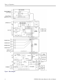
1
xx
ZZZ
WVR5200
Waveform Rasterizer
Service Manual
*P077055100*
077-0551-00
xx
ZZZ
WVR5200
Waveform Rasterizer
Service Manual
www.tektronix.com
077-0551-00
Copyright © Tektronix. All rights reserved. Licensed software products are owned by Tektronix or its subsidiaries
or suppliers, and are protected by national copyright laws and international treaty provisions.
Tektronix products are covered by U.S. and foreign patents, issued and pending. Information in this publication
supersedes that in all previously published material. Specifications and price change privileges reserved.
TEKTRONIX and TEK are registered trademarks of Tektronix, Inc.
Contacting Tektronix
Tektronix, Inc.
14150 SW Karl Braun Drive
P.O. Box 500
Beaverton, OR 97077
USA
For product information, sales, service, and technical support:
In North America, call 1-800-833-9200.
Worldwide, visit www.tektronix.com to find contacts in your area.
Warranty
Tektronix warrants that this product will be free from defects in materials and workmanship for a period of one (1)
year from the date of shipment. If any such product proves defective during this warranty period, Tektronix, at its
option, either will repair the defective product without charge for parts and labor, or will provide a replacement
in exchange for the defective product. Parts, modules and replacement products used by Tektronix for warranty
work may be new or reconditioned to like new performance. All replaced parts, modules and products become
the property of Tektronix.
In order to obtain service under this warranty, Customer must notify Tektronix of the defect before the expiration of
the warranty period and make suitable arrangements for the performance of service. Customer shall be responsible
for packaging and shipping the defective product to the service center designated by Tektronix, with shipping
charges prepaid. Tektronix shall pay for the return of the product to Customer if the shipment is to a location within
the country in which the Tektronix service center is located. Customer shall be responsible for paying all shipping
charges, duties, taxes, and any other charges for products returned to any other locations.
This warranty shall not apply to any defect, failure or damage caused by improper use or improper or inadequate
maintenance and care. Tektronix shall not be obligated to furnish service under this warranty a) to repair damage
resulting from attempts by personnel other than Tektronix representatives to install, repair or service the product;
b) to repair damage resulting from improper use or connection to incompatible equipment; c) to repair any damage
or malfunction caused by the use of non-Tektronix supplies; or d) to service a product that has been modified or
integrated with other products when the effect of such modification or integration increases the time or difficulty
of servicing the product.
THIS WARRANTY IS GIVEN BY TEKTRONIX WITH RESPECT TO THE PRODUCT IN LIEU OF ANY
OTHER WARRANTIES, EXPRESS OR IMPLIED. TEKTRONIX AND ITS VENDORS DISCLAIM ANY
IMPLIED WARRANTIES OF MERCHANTABILITY OR FITNESS FOR A PARTICULAR PURPOSE.
TEKTRONIX' RESPONSIBILITY TO REPAIR OR REPLACE DEFECTIVE PRODUCTS IS THE SOLE
AND EXCLUSIVE REMEDY PROVIDED TO THE CUSTOMER FOR BREACH OF THIS WARRANTY.
TEKTRONIX AND ITS VENDORS WILL NOT BE LIABLE FOR ANY INDIRECT, SPECIAL, INCIDENTAL,
OR CONSEQUENTIAL DAMAGES IRRESPECTIVE OF WHETHER TEKTRONIX OR THE VENDOR HAS
ADVANCE NOTICE OF THE POSSIBILITY OF SUCH DAMAGES.
[W2 – 15AUG04]
Table of Contents
General Safety Summary .........................................................................................
Service Safety Summary..........................................................................................
Preface .............................................................................................................
Manual Conventions.........................................................................................
Related Manuals .............................................................................................
Introduction .........................................................................................................
Service Strategy................................................................................................
Specifications...................................................................................................
Performance Verification......................................................................................
Options and Accessories ......................................................................................
Configurations..................................................................................................
Hardware Installation..........................................................................................
Product Upgrade ...............................................................................................
Operating Information.........................................................................................
Theory of Operation................................................................................................
CPU Board .....................................................................................................
Front Panel .....................................................................................................
Audio (Option AUD)..........................................................................................
Fan Control .....................................................................................................
Power Supply and Distribution...............................................................................
General Maintenance...............................................................................................
Preventing ESD ................................................................................................
Inspection and Cleaning......................................................................................
Troubleshooting....................................................................................................
Getting Started ................................................................................................
Detailed Troubleshooting Procedures ......................................................................
Removal and Replacement Procedures .........................................................................
Preparation.....................................................................................................
Module Removal..............................................................................................
Repackaging Instructions .........................................................................................
Packaging ......................................................................................................
Shipping to the Service Center ..............................................................................
Replaceable Parts ..................................................................................................
Parts Ordering Information ..................................................................................
Using the Replaceable Parts Lists...........................................................................
WVR5200 Waveform Rasterizer Service Manual
iv
vi
vii
vii
vii
1
1
1
1
1
1
1
2
2
3
5
6
6
7
7
9
9
10
13
13
16
22
22
24
27
27
27
29
29
30
i
Table of Contents
List of Figures
Figure 1:
Figure 2:
Figure 3:
Figure 4:
ii
Block diagram .......................................................................................... 4
SDI board ............................................................................................... 18
Fan and main chassis .................................................................................. 26
WVR5200 Exploded view ............................................................................ 32
WVR5200 Waveform Rasterizer Service Manual
Table of Contents
List of Tables
Table i: Related documentation .................................................................................
Table 1: External inspection check list..........................................................................
Table 2: Internal inspection check list...........................................................................
Table 3: Required test equipment................................................................................
Table 4: Symptoms and causes ..................................................................................
Table 5: SDI board basic supplies ...............................................................................
Table 6: Tools required for module removal ...................................................................
WVR5200 Waveform Rasterizer Service Manual
vii
11
11
14
15
17
23
iii
General Safety Summary
General Safety Summary
Review the following safety precautions to avoid injury and prevent damage to
this product or any products connected to it.
To avoid potential hazards, use this product only as specified.
Only qualified personnel should perform service procedures.
To Avoid Fire or Personal
Injury
Use proper power cord. Use only the power cord specified for this product and
certified for the country of use.
Ground the product. This product is grounded through the grounding conductor
of the power cord. To avoid electric shock, the grounding conductor must be
connected to earth ground. Before making connections to the input or output
terminals of the product, ensure that the product is properly grounded.
Observe all terminal ratings. To avoid fire or shock hazard, observe all ratings
and markings on the product. Consult the product manual for further ratings
information before making connections to the product.
Do not apply a potential to any terminal, including the common terminal, that
exceeds the maximum rating of that terminal.
Power disconnect. The power cord disconnects the product from the power source.
Do not block the power cord; it must remain accessible to the user at all times.
Do not operate without covers. Do not operate this product with covers or panels
removed.
Do not operate with suspected failures. If you suspect that there is damage to this
product, have it inspected by qualified service personnel.
Avoid exposed circuitry. Do not touch exposed connections and components when
power is present.
Use proper AC adapter. Use only the AC adapter specified for this product.
Do not operate in wet/damp conditions.
Do not operate in an explosive atmosphere.
Keep product surfaces clean and dry.
Provide proper ventilation. Refer to the manual's installation instructions for details
on installing the product so it has proper ventilation.
iv
WVR5200 Waveform Rasterizer Service Manual
General Safety Summary
Terms in This Manual
These terms may appear in this manual:
WARNING. Warning statements identify conditions or practices that could result
in injury or loss of life.
CAUTION. Caution statements identify conditions or practices that could result in
damage to this product or other property.
Symbols and Terms on the
Product
These terms may appear on the product:
DANGER indicates an injury hazard immediately accessible as you read
the marking.
WARNING indicates an injury hazard not immediately accessible as you
read the marking.
CAUTION indicates a hazard to property including the product.
The following symbol(s) may appear on the product:
WVR5200 Waveform Rasterizer Service Manual
v
Service Safety Summary
Service Safety Summary
Only qualified personnel should perform service procedures. Read this Service
Safety Summary and the General Safety Summary before performing any service
procedures.
Do Not Service Alone. Do not perform internal service or adjustments of this
product unless another person capable of rendering first aid and resuscitation is
present.
Disconnect Power. To avoid electric shock, switch off the instrument power, then
disconnect the power cord from the mains power.
Use Care When Servicing With Power On. Dangerous voltages or currents may
exist in this product. Disconnect power, remove battery (if applicable), and
disconnect test leads before removing protective panels, soldering, or replacing
components.
To avoid electric shock, do not touch exposed connections.
vi
WVR5200 Waveform Rasterizer Service Manual
Preface
This manual supports servicing to the module level of the WVR5200 Waveform
Rasterizer, which rasterizes video signals for XGA display. The instrument finds
use as a monitor for broadcasting, production, and post-production environments.
This manual explains how to troubleshoot and service the instrument to the
module level. The manual is divided into the following sections:
Introduction provides a general product description and tells where to find
product installation information.
Theory of Operation provides descriptions of the instrument modules.
Maintenance tells you how to troubleshoot the product to the module level
and how to handle the modules.
Replaceable Parts illustrates the replaceable modules and mechanical parts
and provides replacement part numbers.
Manual Conventions
The following terms and conventions are used throughout this manual:
The terms "rasterizer" and "instrument" are is used interchangeably to refer to
the WVR5200 Waveform Rasterizer.
Related Manuals
This manual assumes you have access to the following manuals when servicing
this product. These manuals ship with the product and are also downloadable
from the Tektronix Web site.
Table i: Related documentation
Item
Purpose
Location
WVR5200 Waveform Rasterizer User
Manual
Operation instructions and explanation
of features
Product Documentation CD
www.tektronix.com/manuals
WVR5200 Waveform Rasterizer
Installation and Safety Instructions,
English, Japanese, Simplified Chinese
Basic installation and safety information
Printed manual Product
Product Documentation CD
www.tektronix.com/manuals
Online Help
In depth operation and UI help
In the instrument: press the HELP button
on the front panel
WVR5200 Waveform Rasterizer Service Manual
vii
Preface
Table i: Related documentation (cont.)
Item
Purpose
Location
WVR5200 Waveform Rasterizer
Specifications and Performance
Verification
Procedure for checking performance and
list of specifications
Product Documentation CD
www.tektronix.com/manuals
WFM Series Waveform Monitors and
WVR Series Waveform Rasterizers
Management Information Base
Programmer Manual
Programmer’s command reference for
controlling the waveform rasterizer
Product Documentation CD
www.tektronix.com/manuals
viii
WVR5200 Waveform Rasterizer Service Manual
Introduction
The WVR5200 Waveform Rasterizer rasterizes serial digital video signals for a
DVI-I display, providing a new standard of display quality and flexibility.
Service Strategy
These products are repaired to the module level at selected Tektronix service
centers. Repair includes functional verification of the product.
Specifications
The specifications for this product are found in the WVR5200 Waveform Rasterizer
Specifications and Performance Verification Technical Reference located on the
Product Documentation CD that ships with the product and is published on the
Tektronix Web site. (See page vii, Related Manuals.)
Performance Verification
The performance verification procedures for this product are found in the
WVR5200 Waveform Rasterizer Specifications and Performance Verification
Technical Reference located on the Product Documentation CD that ships with
the product and is published on the Tektronix Web site. (See page vii, Related
Manuals.)
Options and Accessories
The lists of options and accessories for this product are found in the WVR5200
Waveform Rasterizer User Manual located on the Product Documentation CD that
ships with the product and is published on the Tektronix Web site. (See page vii,
Related Manuals.)
Configurations
The base instrument has no hardware upgrade options. Software options are
available to add capabilities such as audio and advanced gamut monitoring. For a
complete list of options, refer to the WVR5200 Waveform Rasterizer User Manual.
Hardware Installation
This product is to be rack mounted. For installation instructions, refer to the
WVR5200 Waveform Rasterizer Installation and Safety Instructions.
WVR5200 Waveform Rasterizer Service Manual
1
Introduction
Product Upgrade
Software upgrades are available for all products as free software downloads
from the Tektronix Web site. The WVR5200 Waveform Rasterizer User Manual
includes instructions for updating product software. If you would like to purchase
additional features and capabilities for your instrument, contact Tektronix for
more information on purchasable options. For a complete list of options, refer
to the WVR5200 Waveform Rasterizer User Manual.
Operating Information
For basic operating instructions, refer to the WVR5200 Waveform Rasterizer
User Manual. For more detailed reference information, refer to the instrument
Online help. (Press the Help button on the instrument front panel and then use
the General knob, up/down arrow keys, and SEL button to navigate through
the topics.)
Power-On Procedure
1. Connect the supplied power cord to the external AC adapter, and connect its
XLR output connector to the instrument.
2. Press the power button on the instrument front-panel and the instrument will
turn on.
3. Wait for the system to complete its power-on self-tests.
Power-Down Procedure
1. Press the power button on the instrument front-panel to turn the instrument off.
2. To remove power completely, disconnect the power cord from the AC adapter.
NOTE. The power button on the front-panel does not disconnect the mains power.
Only the power cord at the AC adapter can disconnect the mains power.
2
WVR5200 Waveform Rasterizer Service Manual
Theory of Operation
This instrument is modular. It includes extensive standard capabilities, which can
be augmented by adding various options.
This instrument has outputs to drive an external monitor as well as a serial digital
picture monitor.
This theory of operation is based on the high-level block diagram. (See Figure 1.)
The primary functions on the CPU board are:
Control processor kernel
Front panel interface
Fan controller
Headphones output and control
USB and network connections
Various secondary power supplies
The primary functions on the SDI board are:
SDI input signal conditioning
Input power conditioning and control
The primary functions on the FPGA board are:
Serial digital input processing
Waveform and picture processing for display
DVI output
Reference input data processing
SDI output generation
The block diagram reflects the physical arrangement of circuit boards with the
CPU board at the bottom, the SDI board in the center, and the FPGA board at the
top. Connectors to the External Reference and Front Panel boards are shown.
Power Distribution is not shown in the block diagram but is covered at the end of
this section.
WVR5200 Waveform Rasterizer Service Manual
3
Theory of Operation
Figure 1: Block diagram
4
WVR5200 Waveform Rasterizer Service Manual
Theory of Operation
CPU Board
Serial Digital Input
Processing
The serial digital circuitry receives the SDI input streams from the SDI board
after they have been equalized. The SDI streams are passed to the DSP FPGAs
where they undergo measurement and raster processing. The signal information
is then passed to the DSY FPGA for picture processing, recursion, and display
combining. The result is provided to the external DVI-I connector.
Reference Input
The reference input is a passive loopthrough, which is AC coupled and buffered.
The reference signal is applied to a sync separator whose output is supplied to the
DSP FPGA, where the timing information is derived. The reference signal is also
digitized for display as a waveform.
Digital Waveform
Processing Engine
The data streams from the SDI video inputs are applied to the waveform
processing FPGA. This block deformats, up-samples, interpolates, and otherwise
processes the data to generate the signals needed to create the displays.
Rasterizing Engine
The rasterizer engine resides in the same DSP FPGA as the waveform processing
engine. This block builds up the variable intensity images in the fast static RAM.
For each pixel of the display, the rasterizer engine increments the intensity of that
pixel every time the waveform hits its coordinates. As a result, the waveform
areas that are hit more frequently are brighter. For any given frame, the intensity
map is built up in one memory chip and read out of the other. The functions
swap on the next field.
Recursion and Picture
Processing Engine
The output of the rasterizing engine feeds the picture and recursive processing
engine in the second large FPGA. This engine adds the previous frame to the
present frame to reduce flicker and improve brightness. It also converts the picture
and waveform signals from various input frames rates to 60 Hz frame rate to work
with the DVI-I monitor. The picture and waveform data are then combined with
the graphics and audio bar information from the control processor. The result is
sent through the DVI connector to the external monitor.
CPU Board Control
Processor
The control processor is in charge of all the operational modes in the instrument.
It draws the audio bars, communicates with the front panel, and controls most
other internal devices though either the SPI or the I2C bus.
The control processor interfaces to the Ethernet through a dual rate connection.
This allows the network connection to run at 10 or 100 MBps.
WVR5200 Waveform Rasterizer Service Manual
5
Theory of Operation
LTC
LTC inputs come from the remote connector. The LTC signal is applied to an A/D
converter and then input to the waveform processing FPGA, which decodes the
time code information.
NOTE. The FPGAs decode VITC signals digitally.
Front Panel
The front panel contains a small processor which communicates with the control
processor through SPI signaling. Reprogramming can be done through the SPI if
the front panel processor flash code must be updated.
Audio (Option AUD)
The audio option enables display of levels and phase of embedded audio, and
drives the headphones output.
Audio Processing
The display FPGA extracts embedded audio data from the selected SDI data
stream and sends it to the headphones output D/A converter on the CPU board.
The FPGA also calculates the peak values for the selected meter ballistics
(response characteristics).
The audio data has two paths to the display. On one path, peak values are read
by the control processor, which then plots the bar and surround displays. On the
second path, raw data samples are sent to the waveform processing engine, which
interpolates and plots it to generate the lissajous, or “phase,” display.
6
WVR5200 Waveform Rasterizer Service Manual
Theory of Operation
Fan Control
There are multiple temperature sensors in different locations in the instrument.
The control processor reads the temperature sensors and sets a target speed for
the fans. The fan circuit holds the fan speed at the target by measuring the fan
tachometer output, allowing reliable operation at low speed. If a fan is not
turning, the circuit senses the stall and turns on a red LED (DS2 or DS3 on the
CPU board). The fans are tested at power on. If a fan fails, a message is shown on
screen and also entered into the diagnostic log.
Power Supply and Distribution
External power may be supplied by either the provided power module or a
customer-supplied 11-17 V DC power source. Protection circuits include a
self-resetting fuse, transient filtering, and limiting, over- and under-voltage
protection and current limiting. A latching relay controls standby mode. The
nominal 12 V DC input powers 5 V and 3.3 V supplies. All three voltages are
distributed to the CPU and FPGA boards to power circuits as well as lower
voltage local regulators.
WVR5200 Waveform Rasterizer Service Manual
7
Theory of Operation
8
WVR5200 Waveform Rasterizer Service Manual
General Maintenance
This section contains the information needed to perform periodic and corrective
maintenance on the instrument. The following subsections are included:
Preventing ESD – General information on preventing damage by electrostatic
discharge.
Inspection and Cleaning – Information and procedures for inspecting and
cleaning the instrument.
Troubleshooting – Information for isolating and troubleshooting failed
modules. Included are instructions for operating the diagnostic routines and
troubleshooting trees. Most of the trees make use of the internal diagnostic
routines to speed fault isolation to a module.
Removal and Replacement Procedures – Information and procedures for
removing and replacing modules in the instrument.
Repackaging Instructions – Information on returning a instrument for service.
Preventing ESD
Before servicing this product, read the Safety Summary and Introduction at the
front of the manual and the ESD information below.
CAUTION. Static discharge can damage any semiconductor component in the
instrument.
When performing any service that requires internal access to the instrument,
adhere to the following precautions to avoid damaging internal modules and their
components due to electrostatic discharge (ESD):
1. Minimize handling of static-sensitive circuit boards and components.
2. Transport and store static-sensitive modules in their static protected containers
or on a metal rail. Label any package that contains static-sensitive boards.
3. Discharge the static voltage from your body by wearing a grounded antistatic
wrist strap while handling these modules. Do service of static-sensitive
modules only at a static-free work station.
4. Nothing capable of generating or holding a static charge should be allowed
on the work station surface.
5. Handle circuit boards by the edges when possible.
WVR5200 Waveform Rasterizer Service Manual
9
General Maintenance
6. Do not slide the circuit boards over any surface.
7. Avoid handling circuit boards in areas that have a floor or work-surface
covering capable of generating a static charge.
Inspection and Cleaning
Inspection and Cleaning describes how to inspect for dirt and damage. It also
describes how to clean the exterior and interior of the instrument. Inspection and
cleaning are done as preventive maintenance. Preventive maintenance, when done
regularly, may prevent malfunction and enhance reliability.
Preventive maintenance consists of visually inspecting and cleaning the
instrument and using general care when operating it.
How often maintenance should be performed depends on the severity of the
environment in which the instrument is used. A proper time to perform preventive
maintenance is just before any instrument adjustment.
General Care
The cabinet helps keep dust out and should normally be in place during operation.
WARNING. To prevent injury or death, power off the instrument and disconnect it
from line voltage before performing any procedure that follows.
Interior Cleaning
Use a dry, low-velocity stream of air to clean the interior of the chassis. Use a
soft-bristle, non-static-producing brush for cleaning around components. If you
must use a liquid for minor interior cleaning, use a 75% isopropyl alcohol solution
and rinse with deionized water.
Exterior Cleaning
Clean the exterior surfaces of the chassis with a dry lint-free cloth or a soft-bristle
brush. If any dirt remains, use a cloth or swab dipped in a 75% isopropyl alcohol
solution. Use a swab to clean narrow spaces around controls and connectors. Do
not use abrasive compounds on any part of the instrument that may damage the
chassis.
CAUTION. Avoid the use of chemical cleaning agents that might damage the
plastics used in the instrument. Use only deionized water when cleaning the
front-panel buttons. Use a 75% isopropyl alcohol solution as a cleaner and
rinse with deionized water. Before using any other type of cleaner, consult your
Tektronix Service Center or representative.
10
WVR5200 Waveform Rasterizer Service Manual
General Maintenance
Inspection — Exterior. Inspect the outside of the instrument for damage, wear, and
missing parts, using the following table as a guide. Immediately repair defects
that could cause personal injury or lead to further damage to the instrument.
Table 1: External inspection check list
Item
Inspect for
Repair action
Front panel and top cover
Cracks, scratches,
deformations, damaged
hardware
Repair or replace defective
module
Front-panel knobs
Missing, damaged, or loose
knobs
Repair or replace missing or
defective knobs
Connectors
Broken shells, cracked
insulation, and deformed
contacts. Dirt in connectors
Repair or replace defective
modules. Clear or wash out
dirt
Rackmount slides
Correct operation
Repair or replace defective
module
Accessories
Missing items or parts of
items, bent pins, broken or
frayed cables, and damaged
connectors
Repair or replace damaged
or missing items, frayed
cables, and defective
modules
Inspection — Interior. To access the inside of the instrument for inspection and
cleaning, you will need to remove the top cover.
Inspect the internal portions of the instrument for damage and wear, using the
following table as a guide. Defects found should be repaired immediately.
If any circuit board is repaired or replaced, check the following table to see if it
is necessary to adjust the instrument.
CAUTION. To prevent damage from electrical arcing, ensure that circuit boards
and components are dry before applying power to the instrument.
Table 2: Internal inspection check list
Item
Inspect for
Repair action
Circuit boards
Loose, broken, or corroded
solder connections.
Burned circuit boards.
Burned, broken, or cracked
circuit-run plating.
Remove and replace
damaged circuit board.
Resistors
Burned, cracked, broken,
blistered condition.
Remove and replace
damaged circuit board.
Solder connections
Cold solder or rosin joints.
Resolder joint and clean
with isopropyl alcohol.
WVR5200 Waveform Rasterizer Service Manual
11
General Maintenance
Table 2: Internal inspection check list (cont.)
Item
Inspect for
Repair action
Capacitors
Damaged or leaking cases.
Corroded solder on leads or
terminals.
Remove and replace
damaged circuit board.
Wiring and cables
Loose plugs or connectors.
Burned, broken, or frayed
wiring.
Firmly seat connectors.
Repair or replace modules
with defective wires or
cables.
Chassis
Dents, deformations, and
damaged hardware.
Straighten, repair, or replace
defective hardware.
Cleaning Procedure – Interior. To clean the instrument interior, perform the
following steps:
1. Blow off dust with dry, low-pressure, deionized air (approximately 9 psi).
2. Remove any remaining dust with a lint-free cloth dampened in isopropyl
alcohol (75% solution) and rinse with warm deionized water. (A cotton-tipped
applicator is useful for cleaning in narrow spaces and on circuit boards.)
STOP. If, after doing steps 1 and 2, a module is clean upon inspection, skip
the remaining steps.
3. If steps 1 and 2 do not remove all the dust or dirt, the instrument may be spray
washed using a solution of 75% isopropyl alcohol by doing steps 4 through 6.
4. Gain access to the parts to be cleaned by removing easily accessible shields
and panels.
5. Spray wash dirty parts with the isopropyl alcohol and wait 60 seconds for the
majority of the alcohol to evaporate.
6. Dry all parts with low-pressure, deionized air.
Lubrication. There is no periodic lubrication required for the instrument.
12
WVR5200 Waveform Rasterizer Service Manual
Troubleshooting
Troubleshooting
The procedures in this section will help you trace the root cause of a problem back
to one of the replaceable modules. In general, this is a board-level replacement
but there are a few components on some boards that are replaceable.
WARNING. Before performing this or any other procedure in this manual, read the
General Safety Summary and Service Safety Summary found at the beginning of
this manual.
To prevent possible injury to service personnel or damage to electrical component,
refer on how to prevent ESD. (See page 9.).
Getting Started
This procedure consists of two main sections: the first section contains the
Symptoms and Causes table, and the second section contains a set of Detailed
Troubleshooting Procedures. The table lists common problems and should
help you identify the problem or it may direct you to one of the detailed
troubleshooting procedures in the second section. You should investigate and
resolve the first symptom found, as the Symptoms and Causes table assumes that
the functions covered earlier in the table are working correctly. If you do not find
your instrument's problem in the table, or if no specific problem was reported by
the user, then follow the steps in the Unknown Problem section in the Symptoms
and Causes table.
The WVR5200 Waveform Rasterizer is highly configurable, and its behavior is
sometimes complex. Before troubleshooting in-depth, verify that:
The installed options are as expected. See CONFIG > Utilities > View
Instrument Options
The current settings support the expected behavior. A good first step is to
recall the Factory Presets. To do this, press PRESET > Recall Preset > Recall
Factory Preset.
To fully test this instrument, you must have an appropriate Serial Digital Video
source. In some cases, you may also need receivers or an oscilloscope to check
outputs.
This instrument consists of several boards and major components. The objective
of this troubleshooting guide is to isolate a problem to a module or board so it
can be replaced. This guide does not provide information to troubleshoot to the
component level.
WVR5200 Waveform Rasterizer Service Manual
13
Troubleshooting
Standard boards and modules:
Power Supply (external)
FPGA board
CPU board
SDI board
External Reference I/O board
Table 3: Required test equipment
Test equipment
Requirements
Example
SDI serial digital video test generator with
embedded audio. Instruments with option
3G require a 3 Gb/s SDI source.
1080p 59.94 3 Gb/s signals required:
Tektronix TG700 with an HD3G7 module
(Embedded audio needed for audio
options)
100% color bars
SDI Matrix Split Field Pathological
Signal
1080i 59.94 HD signals required:
Tektronix TG700 with HDVG7 module
(Embedded audio needed for audio
options)
100% color bars
10 bit shallow ramp
SDI Matrix Split Field Pathological
Signal
100% sweep
525/270 SD signals required:
Tektronix TG700 with DVG7 module
(Embedded audio needed for audio
options)
100% color bars
10 bit shallow ramp
SDI Matrix Pathological Signal
100% sweep
XGA Monitor
Computer monitor capable of 1024 x 768
x 60 Hz scan rate
Voltmeter
Oscilloscope
14
Fluke 87 or equivalent
Video trigger capability
Tektronix TDS3000C Series, Tektronix
DPO70404
WVR5200 Waveform Rasterizer Service Manual
Troubleshooting
Table 4: Symptoms and causes
Symptom
Possible cause or detailed troubleshooting procedure to follow
No LEDs lit and no external display
Perform General Checks
Perform Power Switch Checks
Perform Basic Power Supply checks
Some LEDs lit, but no external
display
Perform General Checks
Verify external monitor functionality with another XVGA source
Perform Basic Power Supply Fault Checks
Perform CPU Boot Checks
External display does not function
normally
Verify external monitor functionality with another XVGA source
Replace FPGA board
The front panel buttons are all
dark or inoperative
Check front panel cable
Replace front panel assembly
Power Up Diagnostic failures:
Faults referring to Main or
CPU board
Replace CPU board
Faults referring to FPGA
functions
Replace FPGA board
Fan faults
Perform Fan Checks
Advanced Diagnostics failures:
Replace FPGA board
Functional or Performance
Verification Test Failures:
Perform Power Up Diagnostics
Perform Advanced Diagnostics
Perform Diagnostic Monitor Voltage Checks
Use the table below to isolate the
faulty module based on problem
area:
SDI in, one channel bad
Replace SDI board
SDI in, all four channels bad
Replace FPGA board
Waveform or graphic displays
corrupted
Replace FPGA board
SDI OUT
Replace FPGA board
Audio bars bad
Replace FPGA board
USB bad
Replace CPU board
Ethernet bad
Replace CPU board
Fans bad
Perform Fan checks
Headphones bad, audio bars
ok
Replace CPU board
Reference or LTC waveform
bad
Check Reference I/O cable
Replace Reference I/O board
WVR5200 Waveform Rasterizer Service Manual
15
Troubleshooting
Table 4: Symptoms and causes (cont.)
Symptom
Possible cause or detailed troubleshooting procedure to follow
Ground closure input or
Alarm output bad
Unknown Problems
An instrument may come into
service with vague or intermittent
symptoms. In a case like this, the
following set of tests may help
find the problem or the marginal
condition.
Check Reference I/O cable
Replace Reference I/O board
1. Check the diagnostic log. This log records a variety of problems and will enable you to see
messages for an error that may not be currently happening.
2. Check the power supplies by performing the Diagnostic Monitor Voltage Checks. A marginal
supply can lead to intermittent operation if it is near the acceptable threshold. This includes the
external power source and the secondary supplies on each board.
3. Perform the incoming inspection tests. This will exercise a majority of the functions in the
unit and includes the Advanced Diagnostics. Some parts of the test may not be necessary
for all problem areas.
Detailed Troubleshooting Procedures
The following tests should be run as indicated in the Symptom and Causes table.
(See Table 4 on page 15.). The procedures check for specific problems or will help
you isolate a problem to a board. You can run them at any time for informational
purposes, but if you do not run the procedures in the correct context, then the final
recommendation identifying a root cause might be suspect.
General Checks
1. Verify that the external power is connected, stable and between 10 and 19 Vdc.
2. Check that all internal cables are correctly connected and seated.
3. Check for any discolored or burned components.
Power Switch Checks
This procedure requires partial disassembly and should only be performed if the
unit fails to show any indication of operation. This procedure may also be used to
troubleshoot a unit that cannot be powered off from the front panel power button.
Remove the Reference I/O and FPGA boards to gain access to the SDI board test
points. Connect power and measure the voltage at power connector J7 pin 4 with
respect to chassis ground. The external power supply voltage (10 to 19 Vdc)
should be present at this pin.
If no LEDs are lit on the front panel or CPU board, press the front panel power
button to check that the initial problem is still present. If there is still no indication
of power up, press button S1 on the SDI board. If S1 also has no effect, replace
the SDI board.
If S1 causes normal power up (indicated by lit red and green LEDs on the CPU
board), then the problem is in the connection from the front panel button to the
SDI board. Disconnect power, disassemble as necessary, and check for continuity
or low resistance of the following links:
16
WVR5200 Waveform Rasterizer Service Manual
Troubleshooting
Button resistance: On the front panel board, resistance from J1 pin 2 to
ground should be less than 1000 ohms when the power button pressed, greater
than 20k ohms when released.
Front panel cable continuity: Resistance from Front Panel board J1 pin 2 to
CPU board J1 pin 2 should be less than 10 ohms.
CPU board continuity: Resistance from J1 pin 2 to J2 pin 211 should be less
than 10 ohms.
SDI board continuity : Resistance from J2 pin 211 to switch S1 pins nearest
the edge of the board should be less than 10 ohms.
Replace any cable or board that fails the resistance checks.
Basic Power Supply
Checks
This section describes methods for verifying the proper operation of the basic
power supplies on the SDI board. This procedure requires partial disassembly, and
should only be performed if the unit fails to produce evidence of CPU boot up.
WARNING. Internal power supplies are all low voltage so no safety shield is
present.
This instrument requires an external DC power source capable of providing 11 to
17 Vdc at 3A. The provided AC adapter accepts 90 to 264 VAC and outputs around
12 VDC with 4 A capability. This voltage passes through a power switch circuit
on the SDI board, and is present at the "+12V" test point if instrument power is on.
The switched +12V powers +5V and +3.3V switching power supplies, also
located on the SDI board. These three voltages are the basic power supplies
distributed to the rest of the instrument.
Remove the Reference I/O and FPGA boards to gain access to the SDI board
power test points. Locate the +12V, +5V and +3.3V test points on the SDI board.
(See Figure 2.) Measure the voltages with a DVM and check against the allowable
ranges. (See Table 5.) If the voltages are outside of the allowed range, replace the
SDI board. If voltages are within the allowed range, replace the CPU board.
Table 5: SDI board basic supplies
Nominal (+V)
Allowed range (+V)
+12V
11 to 17
+5V
4.85 to 5.15
+3.3V
3.2 to 3.4
WVR5200 Waveform Rasterizer Service Manual
17
Troubleshooting
Figure 2: SDI board
18
WVR5200 Waveform Rasterizer Service Manual
Troubleshooting
Basic Power Supply Fault
Checks
This procedure requires disassembly. It should be performed only if the unit fails
to operate to the point where diagnostics can be run, and if the power button is
continuously lit red. The power button is normally red for about 2 seconds when
the unit is first powered up. In addition, the power button may be red in the case
of any detected hardware fault. To isolate the symptom to a power supply fault, it
is necessary to view the fault LEDs on the SDI board.
Remove the top cover to gain viewing access to the SDI board fault LEDs DS2,
DS3, DS4 and DS5, located on the right edge of the SDI board. These are visible
from above. Connect power and press and hold the power button. If none of the
four fault LEDs is red, then exit this procedure.
LEDs DS1, and DS3 indicate faults on the SDI board. If any one of them is red,
replace the SDI board. If either DS4 or DS5 is lit, then isolate the faulty assembly
by removing them one at a time in the order listed below. Disconnect the power
before removing each assembly, and then reconnect power and press the power
button to test. The first board or cable to be removed which causes an SDI board
fault LED to stop lighting is probably faulty and should be replaced.
1. Reference I/O cable at FPGA board J4
2. FPGA board
3. Display backlight cable at CPU board J5 (remove SDI board to gain access,
then reinstall SDI board)
For the next two steps, test by pressing SDI board switch S1 instead of the
(disconnected) front panel power button:
4. Front panel cable at CPU board J1 (remove SDI board to gain access, then
reinstall SDI board)
5. CPU board (remove SDI board from CPU and test SDI board in isolation)
If any SDI board fault LED DS1 through DS5 is red when the board is tested in
isolation, replace the SDI board.
CPU Boot Checks
The objective of this test is to determine whether CPU+FP+SDI is booting
correctly, in which case the missing external display is an FPGA board fault. If
CPU+FP+SDI is not booting to completion, the Basic Power Supply Fault Checks
decide whether the SDI or CPU+FP is at fault. The primary indicator is the front
panel behavior, which is presumed good based on single-fault assumption. Since
a good unit boots completely with the front panel disconnected, an initial and final
test are done to the front panel to guarantee that the front panel is not hanging boot.
This procedure requires disassembly, and should be performed only if some front
panel buttons light, but the external display is not functional.
Observe the sequence of front panel button illumination at power on. Normal
power up sequence has the following appearance. Time “T” is in seconds.
T=0 : press power button to power up
WVR5200 Waveform Rasterizer Service Manual
19
Troubleshooting
GAIN, SWEEP, MAG buttons light
Initial button lighting sequence starts with <,^,>,V buttons on for about ½ second
each
T=3: All buttons flash for fraction of a second, then all go out out.
The button sequence changes to row-by-row starting with WFM row, then PICT
row, then GAMUT row, then repeating.
T=10 to 20: Power button may turn red.
T=20: Button sequence stops.
T= 28: Brief changes, then all buttons dim (per backlight setting).
T= 32: Previous power down state is restored to buttons. Usually two or three
become bright.
If the power up behavior is similar to that described, then the CPU is booting
correctly and the display fault is likely to be on the FPGA board. Replace the
FPGA board.
If the power up behavior differs from that described above, then perform the Basic
Power Supply Fault Checks to further isolate the faulty module.
Fan Checks
This instrument contains two fans: they are controlled by both hardware and
software. Hardware controls the fans to a certain speed, but software sets the
speed target as a function of the temperature measured on a variety of temperature
sensors.
If a fan fails, its corresponding LED lights up on the CPU board:
Fan 1 fails: LED DS3 lights
Fan 2 fails: LED DS2 lights
A fan failure is sensed through tachometer feedback; a fault will be asserted if
the fan is not connected, is stalled, or if the tachometer feedback line is not
working correctly.
If one fan fails, the control circuit will increase the voltage to the 13.5 V max
level, causing the remaining fan to run at maximum speed.
The normal voltage to drive the fans (pin 1) varies from about 6 V to
13.5 V depending on internal temperature.
If a fan is not spinning, measure the voltage on pin 1 of the connector on that
fan. If the voltage is near 13 V, then replace the fan. If the voltage is not above
10 V, then replace the CPU board.
20
WVR5200 Waveform Rasterizer Service Manual
Troubleshooting
If both fans are spinning, but either LED DS2 or DS3 is lit, the problem is probably
the tachometer feedback line on pin 3 of either fan. Inspect the wiring and
resistors R201, R203, R202, and R204 on the CPU board, and use the oscilloscope
to look for a 3.3 V square wave on the tachometer feedback line. If resistors are
intact but there is no signal on the tachometer line, replace the affected fan.
Power-Up Diagnostics
To examine the Power-up Diagnostics results, press the CONFIG button, then
select Utilities > View Diagnostic Log.
Each power on is indicated by a boot time stamp, followed by a list of power on
tests. If any failures are indicted then refer to the action as noted above.
Advanced Diagnostics
To run the Advanced Diagnostics, press the CONFIG button, then select Utilities
> Run Advanced Diags.
Advanced Diagnostics includes tests that check the interfaces between FPGAs and
memory on the FPGA board. If any of these tests fails, replace the FPGA board.
Diagnostic Monitor Voltage
Checks
This test uses the built-in voltage monitor to check many power supplies on the
SDI, FPGA and CPU boards. It requires successful boot up, display and front
panel operation:
1. Press and hold OTHER, then select Diag Monitor to display the diagnostic
monitor screen.
2. Navigate to pages 2 and 3 to display the power supply voltages. If the “Last”
value of any voltage is outside the allowable range, it will be displayed in red.
Voltage values are updated about every 10 seconds.
3. If any voltage is out of range, replace the faulty module as indicated by the
first word of the displayed line. “Input” indicates the power supply is on
the SDI board.
Front Panel Button
Troubleshooting
Perform this test if the power supplies are good, but none of the buttons are lit
or respond to presses:
1. Cycle the power to the unit. Immediately after power on, three buttons
(GAIN, SWEEP, and MAG) should be lit continuously and the other buttons
should be lit one at a time in a walking pattern.
2. If the buttons are not lit, check the 10 pin cable from the keypad to the main
board J21. If the cable is connected and good, then replace the front panel
assembly.
WVR5200 Waveform Rasterizer Service Manual
21
Removal and Replacement Procedures
Removal and Replacement Procedures
This section contains information about removal and replacement of all modules
in the instrument.
Preparation
WARNING. Before doing this or any other procedure in this manual, read the
safety summaries found at the beginning of this manual. Also, to prevent possible
injury to service personnel or damage to the instrument components, read
Installation in Section 2, and Preventing ESD in this section.
This subsection contains the following items:
This preparatory information that you need to properly do the procedures
that follow.
List of tools required to remove and disassemble all modules.
Procedures for removal and reinstallation of the modules.
WARNING. Before doing any procedure in this subsection, disconnect the power
cord from the line voltage source. Failure to do so could cause serious injury
or death.
NOTE. Read Equipment Required for a list of the tools needed to remove and
install modules in this instrument. (See Table 6 on page 23.) Read the cleaning
procedure before disassembling the instrument for cleaning.
Equipment Required. Most modules in the instrument can be removed with a
screwdriver handle mounted with a size T8 and T10 Torx screwdriver tips and a
22
WVR5200 Waveform Rasterizer Service Manual
Removal and Replacement Procedures
3/16 nut driver. All equipment required to remove and reinstall the modules is
listed in the following table. (See Table 6 on page 23.)
Table 6: Tools required for module removal
Item
no.
Name
Description
General Tool
number
1
Screwdriver handle
Accepts TORX-driver bits
620-440
2
T8 TORX tip
Used to remove screws securing
top cover, rear panel, front panel,
and XLR power connector.
Standard tool
3
T10 TORX tip
Used for removing most instrument
screws. Torx-driver bit for T10 size
screw heads
640-235
4
T15 TORX tip
Used for removing instrument
screws. Torx-driver bit for T15 size
screw heads
640-247
5
1/8 inch flat-bladed
screwdriver
Screwdriver for unlocking cable
connectors
Standard tool
6
Angle-Tip Tweezers
Used to remove front panel knobs
Standard tool
7
3/16
inch nut driver
Used to remove jack screws and
front panel spacer posts
Standard tool
8
5/16
inch nut driver
Used to remove nut on AC ground
lug
Standard tool
9
MA-800G Soldering Aid
(spudger)
Used to remove the front panel trim
Standard tool
10
Soldering iron (15 W)
Used for replacing CPU board
fuses
Standard tool
11
Long nose pliers
Used to compress connector lock
tabs
Standard tool
WVR5200 Waveform Rasterizer Service Manual
23
Removal and Replacement Procedures
Module Removal
The removal of most of the modules is a straightforward process, and can be
determined by a quick study of the exploded diagram in the Replaceable Parts
List. (See Figure 4.) The boards need to be removed in the order listed here.
Top cover
1. Remove the five flat-head 40 X 0.188 T8 screws on the front edge of the top
cover. When reinstalling, tighten these to 8 in/lb.
2. Remove the four flat-head T8 screws on the left side of the top cover and the
four flat-head T8 screws on the right side.
3. Lift the top cover up off the instrument.
Rear panel and reference
I/O Board
1. Turn the instrument over. On the bottom side of the main chassis, remove the
three flat-head 40 X 0.188 T8 screws that attach the rear panel to the chassis.
When reinstalling, tighten these to 8 in/lb.
2. Turn the instrument right side up. Remove the two flat-head 40 X 0.375 T8
screws that secure the 11–17 VDC XLR connector to the rear panel. When
reinstalling, tighten these to 5.5 in/lb.
3. Using a 9/16 wrench, remove the nut and lock washers from the four SDI
female BNC connectors.
4. Using a 3/16 nut driver, remove the 2 DVI jack screws.
5. Remove the nut and lock washer from the SDI Out female BNC connector.
6. Carefully disconnect the cable that leads from the Reference board to J4 on
the FPGA board below.
7. Pull gently and separate the rear panel, with the Reference board still attached,
from the main chassis.
Reference I/O board.
1. Using a 3/16 nut driver, remove the two Remote connector jack screws that
secure the Reference I/O board to the rear panel. When reassembling, tighten
to 4 in/lbs.
2. Remove the nut and lock washers from the two Ref Loop female BNC
connectors using a 9/16 wrench.
3. Pull the Reference board straight back away from the rear panel.
4. Place the Reference board on a static-free work surface.
24
WVR5200 Waveform Rasterizer Service Manual
Removal and Replacement Procedures
FPGA board
1. Remove the three pan-head 40 X 0.187 T10 screws that secure the FPGA
board to the SDI board below it. When reassembling, tighten these screws
to 5.5 in/lb.
2. Lift the FPGA board straight up, to disconnect the inter-board connector on
the bottom of the FPGA board from the SDI board. When reinstalling, make
sure that these connectors are aligned correctly before pushing the FPGA
board down onto the SDI board, and that you don’t clip the fan cable.
3. Place the FPGA board on a static-free work surface.
SDI board
1. Using a 3/16 nut driver, remove the three spacer posts. When reassembling,
tighten the posts to 5.5 in/lbs.
2. Lift the SDI board straight up, in order to disconnect the inter-board connector
on the bottom of the SDI board from the CPU board. When reinstalling, make
sure that these connectors are aligned correctly before pushing the SDI board
down onto the CPU board.
3. Place the SDI board on a static-free work surface.
CPU board
1. Remove the one pan-head 40 X 0.187 T10 screw that secures the CPU board
to the chassis. When reinstalling, tighten this screw to 5.5 in/lb.
2. Using a 3/16 nut driver, remove the three spacer posts. When reassembling,
tighten the posts to 5.5 in/lbs.
3. Gently disconnect the fan cables from J7 and J8 on the CPU board. These
connectors lock in place. Push the release tab, in the middle, to unlatch the
connector. When reinstalling, make sure to push the plug into the connector
until it snaps into place.
4. Gently disconnect the front panel cable from J1 on the CPU board. Pull this
straight away from their connectors, to prevent damage.
5. Tilt the CPU board up slightly and separate it from the main chassis.
6. Place the CPU board on a static-free work surface.
Front Panel
1. Turn the front panel assembly over. Remove the two flat-head 40 X 0.188
T-10 screws on the bottom that secure the front panel assembly to the main
chassis.
2. Pull the front panel assembly forward. Gently pull the cable through the slot
in the main chassis.
3. Gently disconnect the cable from the front panel board and set it aside.
WVR5200 Waveform Rasterizer Service Manual
25
Removal and Replacement Procedures
Remove the front panel board. The front panel board can be removed from the
front panel and replaced, if needed:
1. Remove the three knobs from the front panel.
2. Remove the four pan-head 40 X 0.187 T10 screws that secure the board to the
front panel. When reinstalling, tighten to 5.5 in/lb.
3. Gently separate the board, with elastomer mat attached, from the front panel.
4. Pull off the elastomer mat.
Fan and Main Chassis
1. Remove the four pan-head 40 X 0.625 T10 screws that secure the two fans to
the main chassis.
2. Remove the fans from the main chassis. When reassembling, put the fans
inside the main chassis with the NMB-MAT labels facing towards the inside
of the instrument. Make sure the fans are rotated so that the cables are located
up against the main chassis bottom and on the outer corners. (See Figure 3.)
Figure 3: Fan and main chassis
26
WVR5200 Waveform Rasterizer Service Manual
Repackaging Instructions
Repackaging Instructions
This section contains the information needed to repackage the instrument for
shipment or storage.
Packaging
When repacking the instrument for shipment, use the original packaging. If
the packaging is unavailable or unfit for use, contact your local Tektronix
representative to obtain new packaging. Refer to Contacting Tektronix, following
the copyright statement, for the mailing address, the email address, and phone
number.
Seal the shipping carton with an industrial stapler or strapping tape.
Shipping to the Service Center
Contact the Service Center to get an RMA (Return Material Authorization)
number, and any return or shipping information you may need.
If the instrument is being shipped to a Tektronix Service Center, enclose the
following information:
The RMA number.
The owner's address.
Name and phone number of a contact person.
Type and serial number of the instrument.
Reason for returning.
A complete description of the service required.
Mark the address of the Tektronix Service Center and the return address on the
shipping carton in two prominent locations.
WVR5200 Waveform Rasterizer Service Manual
27
Repackaging Instructions
28
WVR5200 Waveform Rasterizer Service Manual
Replaceable Parts
This section contains a list of the replaceable modules for your instrument. Use
this list to identify and order replacement parts. Note that not all parts listed in
this section are present on every model. The parts present will depend on the
model and options installed.
Parts Ordering Information
Replacement parts are available through your local Tektronix field office or
representative.
Changes to Tektronix products are sometimes made to accommodate improved
components as they become available, and to give you the benefit of the latest
improvements. Therefore, when ordering parts, it is important to include the
following information in your order:
Part number
Instrument type or model number
Instrument serial number
Instrument modification number, if applicable
If you order a part that has been replaced with a different or improved part, your
local Tektronix field office or representative will contact you concerning any
change in part number.
Module Servicing
Modules can be serviced by selecting one of the following three options. Contact
your local Tektronix service center or representative for repair assistance.
Module Exchange. In some cases, you may exchange your module for a
remanufactured module. These modules cost significantly less than new modules
and meet the same factory specifications. For more information about the module
exchange program, call 1-800-833-9200. Outside North America, contact a
Tektronix sales office or distributor; see the Tektronix Web site for a list of offices:
www.tektronix.com.
Module Repair and Return. You may ship your module to us for repair, after
which we will return it to you.
New Modules. You may purchase replacement modules in the same way as other
replacement parts.
WVR5200 Waveform Rasterizer Service Manual
29
Replaceable Parts
Using the Replaceable Parts Lists
This section contains lists of the mechanical and/or electrical components that are
replaceable for your instrument. Use this list to identify and order replacement
parts. The following table describes each column in the parts list.
Column
Column name
Description
1
Figure & index number
Items in this section are referenced by figure and index numbers to the
exploded view illustrations that follow. Orderable modules show the figure
number without an index number.
2
Tektronix part number
Use this part number when ordering replacement parts from Tektronix.
3 and 4
Serial number
Column three indicates the serial number at which the part was first effective.
Column four indicates the serial number at which the part was discontinued.
No entry indicates the part is good for all serial numbers.
5
Qty
This indicates the quantity of parts used.
6
Name & description
An item name is separated from the description by a colon (:). Because of
space limitations, an item name may sometimes appear as incomplete. Use
the U.S. Federal Catalog handbook H6-1 for further item name identification.
Abbreviations
30
Abbreviations conform to American National Standard ANSI Y1.1-1972.
WVR5200 Waveform Rasterizer Service Manual
Replaceable Parts
Fig. & index
number
Tektronix part
number
Qty
Name & description
-1
174-5921-00
1
CABLE FPGA TO REF/IO 40 PIN
-2
211-1117-00
8
SCREW, MACHINE; 4-40 X 0.187, PAN HEAD, STEEL, ZINC FINISH, T-10, TORX DR
-3
214–4748–00
2
HEAT SINK, SEMIC; IC, PGA 11X11/MQUAD/27MM BGA;1.1 X 1.1 X 0.25 H, PIN FIN, AL, BLACK ANODIZE
-4
863-6501-01
1
CIRCUIT BOARD SUBASSY;FPGA
-5
129-1713-00
6
SPACER POST; .276 L, 4-40 M/F .188 HEX
-6
863-6503-01
1
CIRCUIT BOARD SUBASSY;SDI IO
-7
211-0380-00
2
SCREW, MACHINE; 4-40 X 0.375, FLH, STEEL, ZINC FINISH, T8
-8
863-6502-01
1
CIRCUIT BOARD SUBASSY;CPU
-9
146–0109–00
1
BATTERY, DRY; 3.0V, LITHIUM MANGANESE DIOXIDE, 210MAH, 20 X 3.22MM COIN CELL WITH SOLDER
TABS, CR2032-1HF1; SAFETY CONTROLLED
-10
214-5305-00
1
SPRING, GROUND CLIP FRONT PHONE JACK, USB
-11
260–5015–00
1
SWITCH, PUSH; SPST, TACT;50MA, 50V, MOMENTARY, SILVER CONTACTS;KSC221G, GULLWING SMD,
T&R
-12
348-2002-00
1
GASKET, EMI, 0.125 X 0.250 FOAM W/CONDUCTIVE FABRIC
-13
200-5191-00
1
TOP COVER CHASSIS
-14
211-0105-00
18
SCREW, MACHINE; 4-40 X 0.188, FLH, 100 DEG, ZINC PLATED STEEL, T8
-15
333-4652-00
1
PANEL, REAR WVR
-16
214-3903-00
4
VENDOR: LYNTRON...SCREW, JACK; 4-40 X 0.312 LONG, 0.188 H HEX HEAD STAND OFF, 4-40 INT THD, X
0.312 THD EXT 4-40, STEEL, ZINC PLATED
-17
210-1039-01
7
SCREW,MACHINE; M2.5 X 6MM,FLH,STL,CR PL,CROSS REC;3026
-18
220-0497-00
7
NUT, PLAIN, HEX; .5-28 X .562 HEX, BRS, NI (NICKEL) PLATED
-19
878-6504-00
1
CIRCUIT BOARD SUBASSY;REF IO,UNTESTED, 389441200 ROHS COMPLIANT
-20
441-2645-00
1
CHASSIS,MAIN (WVR)
-21
119-7751-00
2
FAN, DC: TUBEAXIAL, 12V, 5.6 CFM
-22
211-0894-00
4
SCREW, MACHINE; 4-40 X 0.625, PNH, STEEL, ZINC FINISH, T-10, TORX DR
-23
174-5492-00
1
CABLE ASSEMBLY, 10 PIN; FP TO MAIN; ROHS TO ROHS.
-24
863-6505-01
1
CIRCUIT BOARD SUBASSY;WVR FP
-25
260-2923-00
1
SWITCH KEYPAD (ELASTOMER MAT WVR)
-26
333-4649-00
1
FRONT PANEL ASSEMBLY, FRONT PANEL
-27
366-0859-00
1
ASSEMBLY, KNOB; .470 DIAMETER, SOFT TOUCH
5-1
WVR5200 Waveform Rasterizer Service Manual
31
Replaceable Parts
Figure 4: WVR5200 Exploded view
32
WVR5200 Waveform Rasterizer Service Manual