1
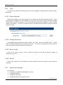
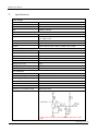
ROIP102 User Manual Cross-Network Gateway (Radio, VOIP, Public Announce) User Manual Model: ROIP102 Version: 1.0 2011-07-13 To save the environment, please view this manual electronically and only print the pages as required. www.hybertone.com ROIP102 User Manual Contents 1. Important Notices .........................................................................................................................................3 2. Out of the Box Check List ..............................................................................................................................4 3. Overview .......................................................................................................................................................5 3.1. Theory of Operation ............................................................................................................................5 3.2. Typical Application Topology ...............................................................................................................6 3.3. Model Nomenclature ..........................................................................................................................6 4. Installation ....................................................................................................................................................6 5. Factory Default Settings ................................................................................................................................8 6. Device Configuration Via Built-in Web Server ..............................................................................................9 6.1. Web Server Login .................................................................................................................................9 6.2. Status ...................................................................................................................................................9 6.3. Configuration .................................................................................................................................... 10 6.3.1. Preference .................................................................................................................................... 10 6.3.2. Network ........................................................................................................................................ 11 6.3.3. Call Settings .................................................................................................................................. 12 6.3.4. PTT Settings .................................................................................................................................. 13 6.3.5. Recorder Settings ......................................................................................................................... 14 6.3.6. Broadcasting Settings ................................................................................................................... 14 6.3.7. Group Codec Settings ................................................................................................................... 14 6.3.8. Save Changes ................................................................................................................................ 14 6.4. 6.4.1. 6.4.2. 6.4.3. 6.4.4. 6.5. 7. Tools.................................................................................................................................................. 15 Online Upgrade ........................................................................................................................... 15 Change Password ........................................................................................................................ 15 Reset Config. ................................................................................................................................ 15 Reboot.......................................................................................................................................... 15 Application Example ......................................................................................................................... 15 Specifications ............................................................................................................................................. 18 www.hybertone.com ROIP102 User Manual 1. 1、 Important Notices This product is used to link up the civilian radio networks, internet, and cellular phone network. Its operation and performance rely on the broadband network connections via private and/or public networks and the cellular phone networks. Due to the stability and reliability of these networks, this product may not be able to link up all the networks connected without any interruptions. Therefore, it is not recommended to use this product in an emergency system or a communication system with zero-failure. 2、 This product can bridge and extend radio networks all over the world. Please consult your local regulations in order to use this product legally. 3、 This product requires the use of dynamic DNS (DDNS) service. For testing purpose, this DDNS service is temporary provided free of charge by Hybertone Technology (Hong Kong). However, this service is not guaranteed without any interruptions. Customers are urged to build their own DDNS server or obtain this service from a DDNS provider. Free DDNS server software may be obtained freely from your local network service provider. 4、 Customers and/or users are taking full responsibilities and all risks in using this product. We are not responsible for any direct or indirect losses caused by, but not limited to, communication failures as a result of product failure or network problems. CUSTOMERS ARE ASSUMED TO HAVE READ AND ACCEPTED WITH FULL UNDERSTANDINGS OF THE IMPORTANT NOTICES STATED ABOVE. www.hybertone.com ROIP102 User Manual 2. Out of the Box Check List Upon unpacking the RoIP102 package, please check the content carefully against the list below. Please report immediately to the supplier for any missing items. Item Appearance Description 1. 1 x Main Unit 2. 1 x AC/DC Adapter Input: 110/220VAC Output: 12VDC, 500mA 3. 3 x PTT Adapter Cables 4. 1 x Ethernet Cable www.hybertone.com ROIP102 User Manual 3. Overview 3.1. Theory of Operation The fundamental of RoIP(Radio over IP)technology is to convert the audio and PTT signals in a radio terminal into IP packets and then transmit the data via the IP networks. The challenge in this technology is to insure that the audio is transmitted in real time and the PPT control signal is securely transmitted. The radio range is general limited by the restricted transmitting power, the antenna sensitivity, and other environmental factors. The successful deployment of this technology extends the coverage of a radio network without using expensive repeaters by linking up multiple radio networks in the world. In addition, this technology can also link up the radio networks to the VoIP networks and the cellular networks. It truly makes voice communications across multiple networks possible. RoIP102 series Cross Network Gateway is designed as a compact and practical device to bridge voice communication between Radio and VoIP networks only. It comes with one standard PTT port for interfacing with only one Radio network. No GSM module is embedded for GSM termination. It simply converts voice signals from a Radio terminal to IP packets and then communicates with a host RoIP302 to form a group with multiple networks as shown in the Basic Network Configuration below. In addition, the built-in relay enables RoIP102 to function as a remote control switch. User can control the built-in relay to switch on or off devices, such as an alarm, a light, a public announce system, an electronic lock, etc. To simplify network setup and configuration, a DDNS client is implemented in RoIP102 to resolve the issue of dynamic public IP addresses with most home and some office network connections. The diagram below shows the concept of how RoIP bridges the voice communications between two radio terminals (at two different locations). At each location, a radio terminal is connected to a RoIP via the PTT Interface Cable provided. Tx is the transmitted audio signal and Rx is the received audio signal. Please note that the Tx signal at RoIP terminal is connected to the Rx signal at radio terminal and vice versa for the Rx signal at RoIP terminal. The PTT signals are the control signal for transmitting and receiving audio signals and they should be connected as shown below. The two RoIPs are connected via internet or intranet in order to create a virtual connection between the two radio terminals. www.hybertone.com ROIP102 User Manual 3.2. Typical Application Topology 3.3. Model Nomenclature 4. Installation The network diagram below shows a basic topology for interconnecting radio terminals at multiple locations. A ROIP302M is used at location A as a centralized point of the interconnection. ROIP102 is used at the other three locations to interface with the local radio terminal and interconnect with the ROIP302M at location A. Radio terminals at these two locations now are interconnected. User in any one of the radio channel can now talk with users at in the other three channels. a) Back Panel www.hybertone.com ROIP102 User Manual Label 1 2 Name CHANNEL SWITCH 3 WAN 4 LAN 5 POWER Description 6-pin RJ11port for PTT Adapter Cable Remote control: Relay switch (220VAC input and 500 mA load current) 10/100Base-T for WAN connection (external network access) 10/100Base-T for LAN connection (internal network access) 12VDC, 500mA b) LED Indicators LED Label RUN Function Device status Channel 1 Channel 1 status Remark Not connected to RoIP302M when flashing at 4 times/sec (fast) Connected to RoIP302M when flashing at twice per seconds (slow) Channel 1 receiving / transmitting c) Channel Port Pin Assignment The channel port is a 6-pin RJ-11 Socket 1. 2. 3. 4. 5. 6. PTTOUT GND Vin (Rx) Aout (Tx) GND PTTIN d) PTT Adapter Cable Wiring Diagram e) Remote Control Wiring Diagram The SWITCH port is a RJ-11 socket with the middle two pins connected to a relay switch. It functions as an ON/OFF switch for controlling an external device or system. www.hybertone.com ROIP102 User Manual Setting up the Main Unit i. Connect the SWITCH Port to an external system for remote ON/OFF control. If the relay switch is connected to high voltage load. The maximum rating for the internal relay is 500mA @ 240VAC load current. ii. Connect the Channel Port to a Radio via the PPT Adapter Cable provided. iii. Connect the WAN Port to a router, network switch, ADSL/Cable Modem for external / public network access. iv. Connect the LAN Port to a local PC or a local Ethernet network (LAN). This allows the local network to access the external network via the WAN port. However, this LAN port is intended for device configuration / low data traffics applications. High data traffics through this port may affect the RoIP102 performance. 5. Factory Default Settings The table below shows the factory default settings. There are two ways to reset to the factory default settings: i. ii. Press the RESET switch for more than 15 seconds. In the Configuration page, select Tools and then Reset Config. Item Login ID Login Password Factory Default Settings admin user admin 1234 WAN Port Setting LAN Port Setting PTT State DHCP 192.168.8.1 “0” is active PTT maximum duration Jitter Delay 60 seconds 60 milliseconds Range Programmable (16 characters in the ASCII table) “0” is active low “1” is active high Less than 600 seconds 20 – 220 milliseconds www.hybertone.com ROIP102 User Manual 6. Device Configuration Via Built-in Web Server The built-in web server provides a comprehensive way to configure the device manually. 6.1. Web Server Login Follow the following procedures to access the RoIP102 via the LAN port. The WAN port is set to DHCP and its IP is obtained from a local DHCP host automatically. It may not be convenient to find out its IP and it would be easier to access the webpage via the LAN port via the following procedures. 1. Connect the LAN port of the RoIP102 to a computer/a local Ethernet network. 2. Configure the computer IP to 192.168.8.x (x = 2 to 254). 3. Type 192.168.8.1 which is the factory preset IP for the RoIP102 LAN port. 4. In the web login window, type “admin” for the login user name and “admin” for the password. Please make sure to save the configurations (click on “Save Changes”) after configuring the device. 6.2. Status This is the default page when you first login to the device web server. It consists of three columns and it is important to understand the information shown in this page in order to debug or report a device problem. www.hybertone.com ROIP102 User Manual 6.3. Configuration The page contains all configuration settings for the RoIP. It is subdivided into various sections/pages for the ease of configuration. The sub-pages include Preference, Network, Call Settings, PTT Settings, GSM Settings, Recorder Settings, Broadcasting Settings, Group Codec Settings, and Group Settings. 6.3.1. Preference The Preference page consists of the common settings for the device and is shown below. The mains settings in this page include: 1. Language – This specifies the language for the webpage and the voice prompts. Currently, only English and Simplified Chinese are supported. 2. Time Zone and Time Server – Time Zone is specified as GMT + or – a fixed value. RoIP acquires the standard GMT time from the Time Server specified. 3. Auto Reboot – This option reboots the device automatically at the time specified. 4. DDNS – When the RoIP is installed in a network environment with dynamic public IP and a SIP server is not used, customer can choose to use our free DDNS service or DDNS offered by other service provider. Enable this option to connect to our DDNS service as shown on the right. The current settings are set to connect to our DDNS server (voipddns.net) using port “39980” and the update time is 600 seconds. Please note that the DDNS Address cannot be set to other DDNS server; this setting only works with our own DDNS server. Once this service is used, the DDNS address for the RoIP is then “<serial number>.com”. The serial number is shown on the bottom label. For example, if the serial number of the device is “R10210120099”, then the DDNS address of this device is “R10210120099.com”. 5. Remote Control – This option allows a user to access the RoIP’s webpage directly from our remote control server. www.hybertone.com ROIP102 User Manual 6.3.2. Network The performance of RoIP102 depends greatly on the network bandwidth available. Proper network environment is the key to insure RoIP102 for optimal performance. High bandwidth leased line network with static public IP is the most preferred network environment for RoIP operation. Shared network with dynamic public IP assignment (PPPoE), like ADSL / Cable modem/router connection, is relatively unstable. RoIP operation is interrupted when link re-establishment occurs since the dynamic IP may be changed to a different IP. In addition, the router / gateway in this network environment is required to configure DMZ mode with its IP set to the WAN IP of the RoIP. Before configuring the Network settings, please first get details of the current network environment. In principle, it is recommended to use a public IP for the WAN port of the RoIP. However, there are 3 choices for the WAN port setting as described below. 1. 2. 3. Static IP – This mode applies to both public and private IP network environment. In the LAN port configuration shown below, select “Static IP” and then fill in the parameters as provided by your network administrator. DHCP – When the device is installed behind NAT and a DHCP host is available, select this mode will enable the device to obtain LAN IP address and other network IPs automatically. PPPoE – For most ADSL and Cable modem access method, the PPPoE dial up is normally used. If the RoIP is connected directly to an access modem, you may need to select the PPPoE. Please consult your ISP for further information if needed. Fill in the User Name and Password as provided by your ISP to complete this LAN port configuration. Another network device can be connected to the PC port. It offers both Bridge and Static IP modes to meet your requirements. The factory preset is Static IP mode with the IP address 192.168.8.1. 1)Bridge Mode Select Bridge mode if your network topology requires the network devices (PC or others) to be in the same network segment. In this case, the device functions as an Ethernet Switch as well. www.hybertone.com ROIP102 User Manual 2)Static IP Mode (Default Setting) Select Static IP mode for a new network segment on PC port. The device now becomes a network router as well. Enter an IP address in IP Address field with a new segment address that is different from the one used in the LAN port. Enter the subnet mask in Subnet Mask field accordingly. A commonly used value is 255.255.255.0. Enable the DHCP Server to set the device as a DHCP host to assign IP Addresses to network devices that are attached to this new network segment. Specify the Starting Address, Ending Address, and Static DNS accordingly. 6.3.3. Call Settings In order for RoIPs to communicate with each other, they need to know their IPs and group relationship. This can be achieved via the following two methods. 1. An external SIP Server – In this configuration, each RoIP registers to the SIP Server which handle all communications among all RoIPs registered. Commands are sent to the SIP Server for processing and then relay to the designated device. Please program the call setting parameters as described below. 2. Group SIP Number = the SIP number created in the SIP Server for this RoIP SIP Proxy = IP address or Domain address of the external SIP Server Authentication ID = the SIP login ID (usually this is the same as the SIP Number) Password = the login password for the SIP login ID Auto Dial Number = the Group SIP Number for the RoIP to dial when establishing a call connection Peer-to-Peer Connection – In this configuration, any one of the RoIPs can be a Host which allows other RoIPs to register to. The host needs to registers to itself as well. Each device www.hybertone.com ROIP102 User Manual needs to have an unique number as an identification for communicating with each other. The table below shows the parameter settings for both Host and Terminal configurations. Calling Settings for Peer-to-Peer Configuration Host Group SIP Number SIP Proxy Terminal an unique number assigned an unique number assigned arbitrary for RoIP identification arbitrary for RoIP identification Host Host IP or DDNS address if IP address address if enabled or DDNS enabled Authentication ID Blank (Not Required) Blank (Not Required) Password Blank (Not Required) Blank (Not Required) Auto Dial Number Blank (Not Required) Designated RoIP Group SIP Number for establishing a voice connection (pressing the PTT control for voice transmit). 6.3.4. PTT Settings This section defines the PPT Signal settings. RoIP102 supports only one PTT port which consists of two control signal (PTT Input (for Rx) and Output (for Tx)). Difference radio terminals may have different requirement on the PTT control signals. Please consult the User Manual of your radio terminal for more information. 1. Input Active Level defines the active level for the PTT Input. Select “1” if the PTT Input is active when the electrical level is high (+5V). Select “0” if the PTT Input is active when the electrical level is low (0V). 2. Output Active Level defines the active level for the PTT Output. Select “1” if the PTT Output is active when the electrical level is high (+5V). Select “0” if the PTT Output is active when the electrical level is low (0V). 3. PTT Output Expiry (s) defines the maximum duration in second for the PTT Output to be active. This means that the maximum transmit time for a voice channel is limited by the PTT Output Expiry. This method is used to prevent a radio terminal to occupy the voice channel indefinitely. The minimum value is 30. www.hybertone.com ROIP102 User Manual 6.3.5. Recorder Settings The recording settings define the address of the recording server. Please refer to the RoIP Voice Recording User Manual for more information. 6.3.6. Broadcasting Settings The RoIP102 provides a relay switch output to control an external system for broadcasting or other applications. A radio user in the group can control this relay switch by dialing DTMF digits on the dialing keypad. When the Broadcasting On Password (DTMF Tones) is received in the audio stream, the relay switch is turn on. When the Broadcasting Off Password is received, the relay switch is turned off. The Broadcasting On Expiry is used to prevent the relay switch from being turned on indefinitely. When the turn duration reaches the Expiry time, the relay switch is shut off automatically. 6.3.7. Group Codec Settings Voice codec is commonly used in voice over IP communications. It enables voice to be compressed in order to save the transmission bandwidth. The higher the compression rate is, the low the transmission bandwidth is required. However, the voice quality is degraded as the compression rate goes higher. In general, a-law, µ-law, and G.729 are commonly used. The transmission rate of a single voice channel is about 82Kbps for a-law or µ-law and about 26Kbps for G.729. However, when a radio station is required to transmit voice data, only a-law or µ-law codec should be selected to minimize the loss in voice quality. It is important to note that all users in the group must use the same codec. 6.3.8. Save Changes To save all changes made, click on “Save Changes” icon on the left panel. The web server will not remind you to save changes when you exit. www.hybertone.com ROIP102 User Manual 6.4. Tools The Tools menu offers the following utilities: Online Upgrade, Change Password, Reset Config., and Reboot. 6.4.1. Online Upgrade Please check regularly with your supplier or our website for the latest firmware release. Copy the upgrade link (address) to the Upgrade Site and then click Start to begin firmware upgrade. Please make sure that the power is not interrupted during firmware upgrade in order to avoid memory corruption. If memory corruption occurs, the RoIP will fail to boot up and will need to return for repair. 6.4.2. Change Password The webpage login passwords for both “admin” and “user” IDs can be modified here. Please make sure that you keep the new password securely. If you lose the password, you will need to reset the device to factory defaults by pressing the 6.4.3. Reset Config. Click on the “Reset Config.” Icon to restore the device to the factory default settings as described in section 5. 6.4.4. Reboot Click on the “Reboot” icon will perform a device cold boot and this will takes a few minutes to complete. 6.5. Application Example Environment: 1. Linking up two MOTO GM300 Radio terminals 2. Using two RoIP102s 3. Using PTP Connection 4. Using ADSL Router for Network Access www.hybertone.com ROIP102 User Manual Setup Procedures: 1. Connect the PTT Interface of the radio terminal (GM300) with the PTT Interface Cable as shown in the diagram below. Connect the RJ-11 plug of the PTT Interface Cable to the PTT port. 2. Connect the RoIP102 LAN port to an Ethernet port of the ADSL Router 3. Assign a fixed IP to the RoIP102 LAN port. This fixed IP must be in the same segment as the LAN port of the ADSL Router. For example: if the LAN of the ADSL Router has an IP 192.168.1.1, then the LAN port RoIP102 could be set to 192.168.1.101. 4. Configure the DMZ mode of the ADSL Router to fixed IP assigned to the RoIP302 LAN port. For DMZ configuration, please refer to the User Manual of your Router. 5. Login to the RoIP Webpage and program the Network Settings as shown below. Please note that the DNS addresses should be programmed as provided by from your local ISP. 6. Next go to the PTT Setting page and set both PTT Input and Output to active low as shown below. 7. Assign the RoIP102 at Location A to be the Host with the Group SIP Number as 101. 8. Go to the Preference Page and enable the DDNS feature. If the serial number of the RoIP102 is R10210120099, then its DDNS address is R10210120099.com www.hybertone.com ROIP102 User Manual 9. Next go to Call Settings page and configure it as shown below. 10. For Codec Settings, choose a-law or µ-law for best voice performance. that both RoIP102s are using the same codec. Please make sure 11. Next configure the RoIP102 at location B as described above with the exception of call settings. 12. Configure the Call Settings page of the RoIP at location B as follows. Please note that it has a different Group SIP Number as the one in location A. Please note that the SIP Proxy address is set to the DDNS address of the RoIP102 at location A. The Auto Dial Number is set to the Group SIP Number of the one at location. This means that 102 calls 101 automatically whenever the PTT control is active (transmitting voice from 102 to 101). 13. At last, the two RoIPs are setup and ready to use. Just push the PTT button at one radio terminal, voice is transmitted to the other radio terminal automatically. If the volume level is not correct, please adjust the 2K Potentiometer located at the PTT Interface adapter cable. www.hybertone.com ROIP102 User Manual 7. Specifications Core Design CPU ARM9 RAM 16MB FLASH 4MB DSP 116MHz, 16 Bit Bus Firmware OS VoIP Protocol Linux (version 2.6) IP、TCP、UDP、HTTP、ICMP、DHCP CLIENT & SERVER、NTP、TFTP、 ToS、DDNS, Telnet SIP v.2 Configuration GUI HTML, XML2.0, JAVA Codecs G.711 (a-law & μ-law), G.729A, G.729AB, G.723.1, GSM Network Protocols Physical & Operation Conditions Power Supply 12VDC, 500mA WAN Port 10/100 Base-T LAN Port 10/100 Base-T SWITCH (Relay) 220VAC input and 500 mA load current Dimension 10cm x 6.8cm x 2.5cm Weight (main unit) 100 g Storage Temperature -40°C - 80°C Operating Temperature (room) 0°C - 40°C PTT Interface PTTIN (Active Low) <0.7V (4.7KΩ load) PTTIN (Active High) >1.2V PTTOUT (High Output) 5V (4.7 KΩ load) PTTOUT (Low Output) 0V Aout 8Ω 750mW 5V P-P Ain 600Ω Internal Impedance, 0 – 0.6Vp-t-p ADJOUT (on the Adapter Cable) 2KΩ Potentiometer PTTIN Circuit * Based on the circuit above, the PPT Input level is high when it is open ended. www.hybertone.com ROIP102 User Manual PTTOUT Circuit www.hybertone.com