1
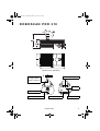
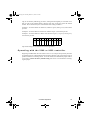
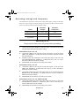
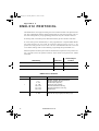
218.FM Page 0 Thursday, March 18, 1999 9:57 AM
RoboScan Pro 218
P/N 35000012
U ser Manual
218.FM Page 1 Thursday, March 18, 1999 9:57 AM
© 1997 - 1999 Martin Professional A/S, Denmark.
All rights reserved. No part of this manual may be
reproduced, in any form or by any means, without
permission in writing from Martin Professional A/S,
Denmark.
Printed in Denmark.
P/N 35000012 Revision #990318-MA
218.FM Page 2 Thursday, March 18, 1999 9:57 AM
ROBOSCAN PRO 218
(dimensions in millimeters)
wrap safety wire
through bracket
bracket mounting bolts
(clamp not shown)
DIP switch
lamp access plate
lamp adjustment screws
serial number label
Exterior View
AC input & fuse
2
218.FM Page 3 Thursday, March 18, 1999 9:57 AM
section 1
INTRODUCTION
Thank you for purchasing the Martin RoboScan Pro 218 moving-mirror intelligent projector. It is designed, built, and programmed to be bright, reliable, safe and easy to use. With
proper setup and maintenance, the RoboScan Pro 218 will provide years of trouble-free
operation.
Please read this manual before operating the RoboScan Pro 218. Safety hazards or damage
to the fixture may occur if it is handled or operated incorrectly. For your protection and
other’s, always follow the safety precautions listed below and observe the warnings in this
manual and printed on the fixture. If you have questions about how to operate and service
the fixture, please contact your Martin dealer for assistance before proceeding. Refer any
service not described in this manual to a qualified Martin technician.
This manual covers the RoboScan Pro 218 with software version 1.4. The latest information
on the RoboScan Pro 218 is always available from your dealer and the Martin web site at
http://www.martin.dk.
Safety Precautions
•
•
•
•
•
•
The RoboScan Pro 218 is NOT for domestic use.
Read user’s manual before connecting or operating the fixture.
Observe all warnings printed on the case.
Always disconnect the fixture from AC power when:
- Changing the transformer or ballast settings
- Installing or removing the lamp
- Checking or replacing fuses
- Removing any cover or part from the fixture.
To reduce risk of fire or electrical shock, do NOT expose to rain or moisture.
Keep the fixture well away from flammable materials.
Do not place the fixture within 1 meter of the surface to be illuminated.
Do NOT block fans or exhaust vents.
Always secure the fixture with approved safety wire.
Always block access below the work area when rigging, derigging, or servicing.
When close to the fixture, do NOT look directly into the light.
Do NOT operate the fixture without the covers or lens. Discharge lamps work under
high pressure and can explode. An unshielded lamp emits dangerous UV radiation
that can cause burns and eye damage.
Allow the fixture to cool for 15 minutes before replacing the lamp.
Do NOT operate the fixture if the ambient temperature (ta) exceeds 40°C (104°F).
•
•
Refer service operations not described in this manual to a qualified technician.
Always ship/transport the fixture in a flight case or its original packaging.
•
•
•
•
•
•
•
•
3
RoboScan Pro 218
218.FM Page 4 Thursday, March 18, 1999 9:57 AM
Features
•
High intensity long-life discharge lamp: the 200 watt Philips MSD 200 or the 150 watt
GE Lighting Arcstream, depending on model.
•
•
•
•
•
•
•
•
•
•
•
•
•
17 dichroic colors plus white (including two multicolors).
17 motorized gobos plus open white.
Pan and tilt movement with microstep precision.
0 to 100% dimming.
High-speed shutter for instant blackout and strobe effects.
Variable speed and tracking control.
Split colors.
Coated precision optics with adjustable focus.
Compatibility with Martin and DMX-512 control protocols.
Built-in random chases with or without music trigger.
Power Factor Correction for low current consumption.
Efficient fan cooling
Overheating protection.
Accessories
Your Martin dealer can provide you with the following RoboScan Pro 218 accessories:
•
•
•
2-unit flight case ...................................................................................... P/N 91505000
4-unit flight case ...................................................................................... P/N 91505001
Floor stand ............................................................................................... P/N 00500109
Introduction
4
218.FM Page 5 Thursday, March 18, 1999 9:57 AM
section 2
INSTALLATION
The RoboScan Pro 218 package includes the following items:
•
Mounting bracket
•
5 meter XLR-XLR cable
•
Power cable
•
User manual
The RoboScan Pro 218 is delivered fully adjusted from the factory; only a few installation
procedures are necessary.
Connecting to the power supply
WA R N I N G !
For safe operation, the fixture must be grounded (earthed).
1.
The RoboScan Pro 218 may be delivered from the factory without a plug on
the power cable. To install a suitable plug (one that fits your local AC outlet),
connect the brown wire to the LIVE pin, the blue wire to the NEUTRAL pin,
and the yellow/green wire to the GROUND pin (earth).
2.
Make sure that the factory settings for voltage and frequency match your
local power supply. If this is not the case, then rewire the RoboScan Pro
218 as described in the Maintenance section. The factory setting is
printed on the serial number label located on the front of the fixture.
3.
Do not apply power to the fixture until the DIP-switch is set as described
in the following sections.
Installing the lamp
The RoboScan Pro 218 is available with either the MSD 200 lamp from Philips or the Arcstream lamp from GE Lighting. These lamps, however, are not interchangeable. Using a
lamp other than the one specified may damage the fixture. The correct lamp is printed
on the label on the front of the Pro 218. See the specifications for additional lamp information.
WARNING!
Before installing the lamp, make sure the
fixture is disconnected from AC power.
5
RoboScan Pro 218
218.FM Page 6 Thursday, March 18, 1999 9:57 AM
1.
Remove the 3 thumbscrews securing the access plate to the back of the
RoboScan and withdraw the lamp-socket assembly.
2.
Holding the lamp in a clean cloth to avoid touching the glass bulb, carefully insert the lamp into the socket.
3.
Clean the lamp with the supplied cloth, particularly if you have touched
the glass bulb.
4.
Replace the lamp-socket assembly and tighten the thumbscrews.
Releasing the pan/tilt lock
To protect the pan/tilt assembly from damage during shipment, it has been secured with two
plastic straps and two thumbscrews.
1.
Cut and remove the plastic straps.
2.
Remove the two thumbscrews on either side of the pan/tilt assembly and
store them in the two threaded holes, B1 and B2, located on the pan/tilt
plate.
3.
Carefully remove the surface protection foil and warning notice from the
mirror.
The entire pan/tilt assembly floats in a special rubber mount. This reduces noise when operating the pan and tilt motors, thus ensuring silent operation. It is strongly suggested that
the pan/tilt assembly be secured during transportation by replacing the two thumbscrews in positions A1 and A2 on either side of the pan/tilt assembly.
Installing the mounting bracket
1.
Place the mounting bracket over the three mounting bolts on the top of the
chassis and secure it with the three M8 self-locking nuts.
2.
When rigging the fixture, wind an approved safety cable through the
mounting bracket and truss.
Installation
6
218.FM Page 7 Thursday, March 18, 1999 9:57 AM
section 3
STAND-ALONE OPERATION
The RoboScan Pro 218 may be operated without a controller in stand-alone mode, in which
the fixture performs a random sequence on its own. To operate the fixture in this mode:
1.
Use the DIP-switch on the front of the fixture to select a stand-alone
sequence. The following table shows the various DIP-switch settings. “Musictrig" sequences use the beat of the music, picked up by the built-in microphone, to trigger the sequence. "Auto-trig" sequences run at a preset speed.
2.
Apply power to the fixture to run the selected sequence.
STAND-ALONE SEQUENCE SETTINGS
Description
7
Pins switched ON
Stand-alone, wide pan/tilt, auto trigger
2, 10
Stand-alone, wide pan/tilt, music trigger
1, 2, 10
Stand-alone, narrow pan/tilt, auto trigger
2, 3, 10
Stand-alone, narrow pan/tilt, music trigger
1, 2, 3, 10
Lamp adjust
8, 10
Adjustment sequence (for service use only)
(1), 5, 10
Adjustment sequence (for service use only)
(1), 6, 10
L.E.D. chase auto-trig (for service use only)
4, 10
L.E.D. chase music-trig (for service use only)
1, 4, 10
RoboScan Pro 218
218.FM Page 8 Thursday, March 18, 1999 9:57 AM
section 4
CONTROLLER OPERATION
The RoboScan Pro 218 may be operated with both DMX-512 and Martin RS-485 protocol
controllers. Instructions are transmitted from the controller via an XLR - XLR cable to the
data input on the RoboScan. The data output allows the serial data link to be continued to
additional fixtures.
To connect a serial data link:
1.
Connect the data output of the controller to the data input on the Pro 218. If
using a Martin controller, use the XLR-XLR / DSUB-XLR cable that came with
the controller. Otherwise, use a cable that fits the DMX controller and the
RoboScan. This is normally a cable that adapts from 5-pin XLR to 3-pin XLR.
The following table shows the pin connections. Note that the (+) and (-) wires
swap from the DMX output to the input on the RoboScan Pro 218. (The cable
is available from Martin as P/N 11820003.)
2.
If only using one fixture, insert an XLR termination plug into the data output socket on the RoboScan. If a Martin controller is being used, then
insert the termination plug that came with the controller (120 Ohm XLR
male). Otherwise, use a termination plug as specified by the controller
manual.
3.
If using more than one lighting fixture with the controller, connect the data
output on each fixture to the data input on the following fixture using
XLR-XLR cables. The order in which you connect the fixtures is not
important and has no influence on channel numbering - use an order
which gives the easiest and shortest cable routing. To ensure proper
transmission on the data link it is important to insert an XLR termination
plug, as described above, in the last fixture on the link.
4.
Use the DIP-switch to select the address on each fixture. If you are not
familiar with this, see the section on address setting below. Ensure that
none of the RoboScans are set to stand-alone mode. All fixtures
should have pin 10 switched OFF.
5.
Switch on and configure the controller. Apply power to the RoboScans.
After a short start-up routine, they are ready for operation.
6.
The RoboScans automatically detect which protocol, Martin or DMX, is
being sent. (This function can be reactivated by switching ON all ten DIPswitches and then resetting the address.)
It is possible to insert non-Martin DMX fixtures with 5-pin XLR connections in the link.
You will need a cable that adapts the 3-pin output on the Martin fixture to the 5-pin input on
the non-Martin fixture. The cable connections are shown in the second table below. (The
cable is available from Martin as P/N 11820002.)
Controller Operation
8
218.FM Page 9 Thursday, March 18, 1999 9:57 AM
Cable Connections (P/N 11820003)
5-pin DMX Output to 3-pin Martin Input
Description
5-pin male XLR
3-pin female XLR
Ground
(screen)
pin 1
pin 1
(-) signal
pin 2
pin 3
(+) signal
pin 3
pin 2
Not used
pin 4
Not used
pin 5
Cable Connections (P/N 11820002)
3-pin Martin output to 5-pin DMX Input
Description
3-pin male XLR
5-pin female XLR
Ground
(screen)
pin 1
pin 1
(-) signal
pin 3
pin 2
(+) signal
pin 2
pin 3
Not used
pin 4
Not used
pin 5
Focusing
With the RoboScan Pro 218 mounted in position, select a gobo and adjust the focus manually to produce a sharp image on the desired target.
Address setting
Besides setting stand-alone sequences, the DIP-switch is also used for setting the channel
address on which the RoboScan Pro 218 responds to the controller. The Pro 218 uses 1
channel when operated via a Martin RS-485 protocol controller. It uses 6 channels when
operated via a DMX-512 controller and DMX mode 1 is selected, and 8 channels when
DMX mode 2 or 3 is selected. Please refer to the DMX table in appendix a.
The procedure for selecting DMX mode is described in the Maintenance section. The
RoboScan Pro 218 is factory-set to DMX mode 3.
The address is selected by switching ON one or more of the 10 DIP-switch pins. Each ON
pin adds the value listed in the following table. OFF pins add no value. The DIP-switch set9
RoboScan Pro 218
218.FM Page 10 Thursday, March 18, 1999 9:57 AM
ting can be found by subtracting pin values, starting from the highest pin value that is less
than or equal to the channel address, until the total value of the pins equals the channel
number. Pin 10 should always be switched OFF when setting an address.
Example 1: To set the address to channel 10, subtract 8 (pin 4) and 2 (pin 2), and set these
pins ON.
Example 2: To set the address to channel 64, subtract 64 (pin 7) and set this pin ON.
Example 3: To set the address to channel 100, subtract 64 (pin 7), 32 (pin 6), and 4 (pin 3),
and set these pins ON.
6
7
8
9
:
;
<
43
;
49
65
97
45;
589
6SHFLDO
4
YDOXH
5
7
4
5
SLQ
Dip-switch settings for all channels are listed in appendix b.
Operating with the 2308 or 2032 controller
Beginning with RoboScan Pro 218 software version 1.4, an improved speed array has been
programmed for use with the Martin 2308 and 2032 controllers. This increases the range of
speeds available for controlling effects. To use this feature, the DMX-mode jumper must be
set to mode 3. This is the factory default setting. See section 7 for information on changing the jumper.
Controller Operation
10
218.FM Page 11 Thursday, March 18, 1999 9:57 AM
section 5
CONTROLLABLE FUNCTIONS
Pan/Tilt
The moving mirror allows you to pan the beam 175° and tilt it 85°. Microstep motors provide smooth and accurate movement at all speeds. DMX modes 1 and 2 offer 8-bit pan/tilt
resolution, while DMX mode 3 and Martin mode provides finer position control with 16-bit
resolution. Selecting the B/O speed blacks out the light while the mirror is moving.
Color wheel
The Pro 218 offers 18 color positions on the color wheel - 15 saturated dichroic colors, 2
multicolors, and open (white). The wheel can be positioned directly on any color, or,
between two adjacent colors, thus splitting the beam into different colors. The acceleration
control allows high-speed scrolling. Selecting B/O speed blacks out the light while scrolling
at the highest speed.
Gobo wheel
The Pro 218 offers 17 different gobos plus open. The wheel can be positioned directly on
any gobo, or, between two adjacent gobos, thus splitting the beam into different patterns.
The acceleration control allows high-speed scrolling. Selecting B/O speed blacks out the
light while scrolling at the highest speed.
Dimmer
Full-range dimming is provided via a motorized mechanical dimmer system. The dimmer
speed is variable.
Shutter
The shutter allows you to switch the light on and off instantly and to create strobe effects.
The strobe frequency is variable up to approximately 12 Hz.
11
RoboScan Pro 218
218.FM Page 12 Thursday, March 18, 1999 9:57 AM
section 6
MAINTENANCE
The RoboScan Pro 218 comes fully adjusted from the factory, however, some adjustments
may be necessary for proper operation, particularly after changing the lamp, extensive use,
or transportation to a new location.
I M P O R TA N T !
Read the procedures before making adjustments. If you are not
experienced servicing electro-mechanical devices, please refer
the work to a qualified technician.
Adjusting the Lamp
The RoboScan Pro 218 comes fully adjusted from the factory, however, readjustment of the
lamp may be necessary due to differences between lamps. The lamp is adjusted by turning
the 3 Phillips-head screws on the lamp access plate. Turning these clockwise pulls the lamp
back towards the rear and vice versa. Keep adjustments small to avoid pulling the lamp so
far off center that it hits the reflector.
NOTE: The lamp is not a hot-restrike type; you must wait approximately 10 minutes after
having turned off the lamp before you can turn it back on again.
WARNING!
The fixture must be cool and disconnected from AC power.
1.
Remove the 3 thumbscrews from the lamp access plate and remove the lamp
assembly.
2.
Make a preliminary adjustment: turn the adjustment screws so that the
inside-to-inside measurement between the lamp socket mounting plate
and the lamp access plate is 13 mm (1/2 in). Replace the lamp assembly.
3.
Flip DIP-switch pins 8 and 10 on. Flip all other pins off.
4.
Apply power to the RoboScan Pro 218. After it has reset, it produces a
white light with an open gobo for adjustment purposes. Wait approximately 5 minutes for the lamp to reach full brightness.
5.
Manually position the fixture and/or mirror so the light shines on a flat
surface and focus the beam.
6.
If there is an off-center “hot spot,” the lamp is not centered in the reflector. “Pull” the hot spot into the center of the field with small adjustments
of one or more of the screws.
Maintenance
12
218.FM Page 13 Thursday, March 18, 1999 9:57 AM
7.
If the light is significantly brighter in the center of the field than it is at the
edge, the lamp is too far forward in the reflector. Pull the lamp in by turning all three screws clockwise 1/4-turn at a time until the light is evenly
distributed.
8.
If the light is brighter around the edge than it is in the center, or if light
output is low, the lamp is too far back in the reflector. “Push” the lamp out
by turning the screws counter-clockwise 1/4-turn at a time until the light is
bright and evenly distributed.
DMX mode selection
Inside the RoboScan Pro 218 is a jumper for selecting the three DMX modes. Mode 3
(jumper on pins 4 and 5) is the factory-set default. Follow the procedure below to enable
mode 1 or 2.
WA R N I N G !
Disconnect the fixture from AC power before proceeding.
1.
Release the 6 screws labelled 'D' and 'C' in figure 1 and carefully remove the
complete pan/tilt section. Avoid unplugging the motor cables from the circuit
board.
2.
Locate the jumper labelled 'PL432' on the circuit board (refer to the
nearby label). To enable mode 1, simply remove this jumper. To enable
mode 2, move the jumper to pins 5 and 6.
3.
Reassemble the fixture before connecting to AC power.
ballast
circuit board
DMX jumper
transformer
Figure 1
13
RoboScan Pro 218
218.FM Page 14 Thursday, March 18, 1999 9:57 AM
Selecting voltage and frequency
The RoboScan Pro 218 must be rewired if the voltage and frequency settings do not match
the local AC power supply. The factory settings are printed on the label on the front of the
fixture. The following table shows the available settings.
Model
Selectable
Voltages
Selectable
Frequencies
RoboScan Pro 218 EU
220 V / 230 V / 245 V
50 Hz
RoboScan Pro 218 US
100 V / 110 V / 120 V
50 Hz / 60 Hz
RoboScan Pro 218
US Arcstream
100 V / 110 V / 120 V
60 Hz
WA R N I N G !
Disconnect the fixture from AC power before proceeding.
1.
Unscrew the 8 screws, labelled 'A' and 'B' in figure 1, that secure the casing
over the lamp housing and remove the casing.
ROBOSCAN PRO 218 US
2. Locate the ballast at the rear-left corner (see figure 1) and move the
GREY wire, labelled 'F', to either the 50 Hz or the 60 Hz terminal to select
the local frequency.
3.
Similarly, locate the transformer at the rear-right corner of the unit, and
move the BROWN wire, labelled 'V', to either the 100 V, 110 V, or 120 V
terminal to select the local AC voltage.
4.
Reassemble the unit before connecting to AC power.
ROBOSCAN PRO 218 EU
2. Locate the ballast at the rear-left corner (see figure 1) and move the
GREY wire, labelled 'V', to either the 220 V, 230 V, or 245 V terminal to
select the local AC voltage.
3.
Locate the transformer at the rear-right corner of the unit and move the
BROWN wire, also labelled 'V', to either the 225 V or 240 V terminal to
select the local AC voltage.
4.
Reassemble the unit before connecting to AC power.
RO BO SCAN PRO 218 US A RC STREA M
2. Locate the transformer at the rear-right corner (see figure 1), and move
the BROWN wire, labelled 'V', to either the 100 V, 110 V, or the 120 V terminal to select the local AC voltage.
3.
Reassemble the unit before connecting to AC power.
Maintenance
14
218.FM Page 15 Thursday, March 18, 1999 9:57 AM
Adjusting the mirror
Readjusting the mechanical stop on the RoboScan Pro 218 mirror adaptor is required if the
pan or tilt motor occasionally loses step, leaving the mirror incorrectly positioned after a
reset. This error occurs when the recoil of the mechanical reset bounces the mirror and
bracket a whole pan or tilt motor step.
Figure 2
PAN ADJUSTMENT
1.
Connect the RoboScan Pro 218 to a controller and set the address. Switch on
the controller and then the RoboScan Pro 218.
2.
Use the controller to move the mirror to the extreme left position, thus
positioning screw A1 in figure 2 at the upper mechanical stop (A2).
3.
Release the lock-nut on adjusting screw A1.
4.
Turn screw A1 clockwise 1/2 - 1 turn to increase the distance between
the head of the screw and the mechanical stop (A2).
5.
Tighten the lock-nut on screw A1.
6.
Reset the RoboScan Pro 218 a number of times to check the new reset
position.
7.
Use the controller to move the mirror through all extreme positions,
checking that adjustment screw B1 does NOT touch the mechanical stop
(B2) during these steps. If it does, then adjust screw B1 accordingly.
TILT ADJUSTMENT
15
1.
Connect the RoboScan Pro 218 to a controller and set the address. Switch on
the controller and then the RoboScan Pro 218.
2.
Use the controller to move the mirror to the upper-left position until the
top mechanical stop (C1 in figure 2) is positioned at the edge of the mirror bracket (C2).
RoboScan Pro 218
218.FM Page 16 Thursday, March 18, 1999 9:57 AM
3.
Loosen the two allen-screws (E) holding the motor axle while taking care
that the motor does not slide vertically from its current position.
4.
Carefully turn the motor and mirror clockwise (make sure the motor axle
does NOT turn) until there is a distance of 1/2 to 1 mm (1/64 - 1/32”)
between the edge of the mirror bracket (C2) and the top mechanical stop
(C1).
5.
Tighten the allen-screws.
6.
Use the controller to reset the fixture and move the mirror through all
extreme positions, checking that the bottom mechanical stop (D1) does
NOT touch the edge of the mirror bracket (D2) during these steps. If it
does, then readjust as described above, making the distance between C2
and C1 even smaller.
Maintenance
16
218.FM Page 17 Thursday, March 18, 1999 9:57 AM
appendix a
DMX-512 PROTOCOL
The RoboScan Pro 218 supports tracking and vector mode and 8 and 16 bit pan/tilt resolution. The 3 DMX modes and the channel requirements for each are shown below. The correct mode will depend on your programming preferences and your controller’s abilities.
In tracking mode, movement speed is determined directly by the controller’s fade time.
In vector mode, speed is determined by a value programmed on a separate DMX channel.
For smooth movement in vector mode, the controller’s fade time must be set to 0, i.e., the
position must bump from the current value to the next. If the RoboScan Pro 218 is set to run
vector mode, tracking mode can be enabled by programming the speed channels to 0.
With 8-bit pan/tilt resolution, pan and tilt are divided into 256 positions. Finer position control is possible with 16-bit pan/tilt resolution, which divides each position into smaller
increments.
DMX Setup
Channels
PL432 Jumper
Location
Mode 1 - 8 bit Pan/Tilt Tracking
6
no jumper
Mode 2 - 8 bit Pan/Tilt Tracking/Vector
8
pin 5 and 6
Mode 3 - 16 bit Pan/Tilt Tracking
8
pin 4 and 5
DMX Protocol, All Modes
Channel
1
2
17
DMX Values
0-5
6 - 80
81 - 208
209 - 230
231 - 252
253 - 255
0 - 255
Effect
Shutter / Strobe / SA / Reset fixture
Shutter Closed (Light off)
Shutter Open (Light on)
Strobe on (Fast Æ Slow)
Remote Stand-alone auto trig
Remote Stand-alone music trig
Reset fixture
Dimmer
Dimmer full ON (no light)Æ full OFF (Light)
RoboScan Pro 218
218.FM Page 18 Thursday, March 18, 1999 9:57 AM
DMX Protocol, All Modes
Channel
DMX Values
Effect
Color
0 - 11
11 - 22
22 - 33
33 - 44
44 - 55
55 - 66
66 - 77
77 - 88
88 - 99
99 - 110
110 - 121
121 - 132
132 - 143
143 - 154
154 - 165
165 - 176
176 - 187
White Æ Flame Red
Flame Red Æ Light Blue
Light Blue Æ Frn. Green
Frn. Green Æ Yellow
Yellow Æ Primary Green
Primary Green Æ Mauve
Mauve Æ Dark Blue
Dark Blue Æ Cyan Blue
Cyan Blue Æ Primary Red
Primary Red Æ Light Orange
Light Orange Æ Light Green
Light Green Æ Amber
Amber Æ Pink
Pink Æ D. Lavender
D. Lavender Æ Dark Orange
Dark Orange Æ Multicolor 1
Multicolor 1Æ Multicolor 2
187 - 190
191 - 193
194 - 196
197 - 199
200 - 202
203 - 205
206 - 208
209 - 211
212 - 214
215 - 217
218 - 220
221 - 223
224 - 226
227 - 229
230 - 232
233 - 235
236 - 238
239 - 255
Multicolor 2
Multicolor 1
Dark Orange
Dark Lavender
Pink
Amber
Light Green
Light Orange
Primary Red
Cyan Blue
Dark Blue
Mauve
Primary Green
Yellow
Frn. Green
Light Blue
Flame Red
White
3
DMX-512 Protocol
18
218.FM Page 19 Thursday, March 18, 1999 9:57 AM
DMX Protocol, All Modes
Channel
DMX Values
Effect
0 - 11
11 - 22
22 - 33
33 - 44
44 - 55
55 - 66
66 - 77
77 - 88
88 - 99
99 - 110
110 - 121
121 - 132
132 - 143
143 - 154
154 - 165
165 - 176
176 - 187
Gobo
Open Æ Half
Half Æ Dot
Dot Æ Pin
Pin Æ Vertical Bar
Vertical Bar Æ Horizontal Bar
Horizontal Bar Æ Cross
Cross Æ Arrow
Arrow Æ Triangles
Triangles Æ Star
Star Æ Holes
Holes Æ Bells
Bells Æ Cone
Cone Æ Cones
Cones Æ Phone
Phone Æ Thin Bars
Thin Bars Æ Window
Window Æ Turbine
187 - 190
191 - 193
194 - 196
197 - 199
200 - 202
203 - 205
206 - 208
209 - 211
212 - 214
215 - 217
218 - 220
221 - 223
224 - 226
227 - 229
230 - 232
233 - 235
236 - 238
239 - 255
Turbine
Window
Thin Bars
Phone
Cones
Cone
Bells
Holes
Star
Triangles
Arrow
Cross
Horizontal Bar
Vertical Bar
Pin
Dot
Half
Open
4
DMX Protocol, MODES 1 and 2 ONLY
Channel
5
6
19
DMX Values
Effect
0 - 255
Pan
Left Æ right (127 = neutral)
0 - 255
Tilt
Up Æ down (127 = neutral)
RoboScan Pro 218
218.FM Page 20 Thursday, March 18, 1999 9:57 AM
DMX Protocol, MODE 2 ONLY
Channel
7
DMX Values
Effect
0
1 - 251
252 - 255
Speed: Pan / Tilt / Movement
Tracking
Speed, fast Æ slow
Blackout while changing
0 - 251
252 - 255
Color / Gobo Speed
Speed, fast Æ slow
Black-out while changing
0 - 251
252 - 255
Dimmer Speed
Speed, fast Æ slow
Speed, fast
8
DMX Protocol, MODE 3 ONLY
Channel
5
6
7
8
DMX Values
Effect
0 - 255
Pan Coarse (MSB)
Left Æ right (127 = neutral)
0 -255
Pan Fine (LSB)
Left Æ right (127 = neutral)
0 -255
Tilt Coarse (MSB)
Up Æ down (127 = neutral)
0 - 255
Tilt Fine (LSB)
Up Æ down (127 = neutral)
DMX-512 Protocol
20
218.FM Page 21 Thursday, March 18, 1999 9:57 AM
appendix b
D I P - S W I T C H TA B L E
This table shows DIP-switch settings for channels 1- 511. To find a setting, locate the channel in the table. Follow the row to the left to find the settings for pins 1 through 5; follow the
column to the top to find the settings for pins 6 through 9. A “0” indicates the pin is turned
off and a “1” indicates the pin is turned on. Pin 10 is always switched OFF when setting a
controller address.
Example: The table shows the setting for channel 212 is 00101 for pins 1 - 5 and 0110 for
pins 6 - 9. Pins 3, 5, 7, and 8 are set to on; pins 1, 2, 4, 6, 9, and 10 are set to off.
',306ZLWFK#6HWWLQJ
&4
3
4
3
4
3
4
3
4
3
4
3
4
3
4
3
4
3
4
3
4
3
4
3
4
3
4
3
4
3
4
3
4
21
3# #2))
4# #21
&5 &6 &7
3 3 3
3 3 3
4 3 3
4 3 3
3 4 3
3 4 3
4 4 3
4 4 3
3 3 4
3 3 4
4 3 4
4 3 4
3 4 4
3 4 4
4 4 4
4 4 4
3 3 3
3 3 3
4 3 3
4 3 3
3 4 3
3 4 3
4 4 3
4 4 3
3 3 4
3 3 4
4 3 4
4 3 4
3 4 4
3 4 4
4 4 4
4 4 4
&8
3
3
3
3
3
3
3
3
3
3
3
3
3
3
3
3
4
4
4
4
4
4
4
4
4
4
4
4
4
4
4
4
&<
&;
&:
&9
3
3
3
3
3
3
3
4
3
3
4
3
3
3
4
4
3
4
3
3
3
4
3
4
3
4
4
3
3
4
4
4
4
3
3
3
4
3
3
4
4
3
4
3
4
3
4
4
4
4
3
3
4
4
3
4
4
4
4
3
4
4
4
4
4
5
6
7
8
9
:
;
<
43
44
45
46
47
48
49
4:
4;
4<
53
54
55
56
57
58
59
5:
5;
5<
63
64
65
66
67
68
69
6:
6;
6<
73
74
75
76
77
78
79
7:
7;
7<
83
84
85
86
87
88
89
8:
8;
8<
93
94
95
96
97
98
99
9:
9;
9<
:3
:4
:5
:6
:7
:8
:9
::
:;
:<
;3
;4
;5
;6
;7
;8
;9
;:
;;
;<
<3
<4
<5
<6
<7
<8
<9
<:
<;
<<
433
434
435
436
437
438
439
43:
43;
43<
443
444
445
446
447
448
449
44:
44;
44<
453
454
455
456
457
458
459
45:
45;
45<
463
464
465
466
467
468
469
46:
46;
46<
473
474
475
476
477
478
479
47:
47;
47<
483
484
485
486
487
488
489
48:
48;
48<
493
494
495
496
497
498
499
49:
49;
49<
4:3
4:4
4:5
4:6
4:7
4:8
4:9
4::
4:;
4:<
4;3
4;4
4;5
4;6
4;7
4;8
4;9
4;:
4;;
4;<
4<3
4<4
4<5
4<6
4<7
4<8
4<9
4<:
4<;
4<<
533
534
535
536
537
538
539
53:
53;
53<
543
544
545
546
547
548
549
54:
54;
54<
553
554
555
556
557
558
559
55:
55;
55<
563
564
565
566
567
568
569
56:
56;
56<
573
574
575
576
577
578
579
57:
57;
57<
583
584
585
586
587
588
589
58:
58;
58<
593
594
595
596
597
598
599
59:
59;
59<
5:3
5:4
5:5
5:6
5:7
5:8
5:9
5::
5:;
5:<
5;3
5;4
5;5
5;6
5;7
5;8
5;9
5;:
5;;
5;<
5<3
5<4
5<5
5<6
5<7
5<8
5<9
5<:
5<;
5<<
633
634
635
636
637
638
639
63:
63;
63<
643
644
645
646
647
648
649
64:
64;
64<
653
654
655
656
657
658
659
65:
65;
65<
663
664
665
666
667
668
669
66:
66;
66<
673
674
675
676
677
678
679
67:
67;
67<
683
684
685
686
687
688
689
68:
68;
68<
693
694
695
696
697
698
699
69:
69;
69<
6:3
6:4
6:5
6:6
6:7
6:8
6:9
6::
6:;
6:<
6;3
6;4
6;5
6;6
6;7
6;8
6;9
6;:
6;;
6;<
6<3
6<4
6<5
6<6
6<7
6<8
6<9
6<:
6<;
6<<
733
734
735
736
737
738
739
73:
73;
73<
743
744
745
746
747
748
749
74:
74;
74<
753
754
755
756
757
758
759
75:
75;
75<
763
764
765
766
767
768
769
76:
76;
76<
773
774
775
776
777
778
779
77:
77;
77<
783
784
785
786
787
788
789
78:
78;
78<
793
794
795
796
797
798
799
79:
79;
79<
7:3
7:4
7:5
7:6
7:7
7:8
7:9
7::
7:;
7:<
7;3
7;4
7;5
7;6
7;7
7;8
7;9
7;:
7;;
7;<
7<3
7<4
7<5
7<6
7<7
7<8
7<9
7<:
7<;
7<<
833
834
835
836
837
838
839
83:
83;
83<
843
844
RoboScan Pro 218
218.FM Page 22 Thursday, March 18, 1999 9:57 AM
appendix c
SPECIFICATIONS
DIMENSIONS
•
Height without mounting bracket .............................................. 185 mm (7.3")
•
Height with mounting bracket ....................................................325 mm (12.6")
•
Length .......................................................................................533 mm (22.0")
•
Width.........................................................................................280 mm (11.1")
•
Weight ........................................................................................... 14 kg (31 lb)
PO W E R A N D C U R R E N T C O N S U M P T I O N
•
EU model ........................................................... 290 W, 1.3 A at 230 V / 50 Hz
•
US model............................................................ 290 W, 2.4 A at 120 V / 60 Hz
•
US Arcstream model ........................................... 220 W, 2.1 A at 120 V / 60 Hz
AC
•
•
•
VO L T AG E A N D F R E Q U E N C Y
EU model ....................................................................... 210 V to 260 V, 50 Hz
US model.............................................................. 95 V to 125 V, 50 Hz / 60 Hz
US Arcstream model ......................................................... 95 V to 125 V, 60 Hz
FUSE
•
size, all models ................................................................................. 5 x 20 mm
•
EU model .........................................................................T (time delay) 3.15 A
•
US model..........................................................................T (time delay) 6.30 A
•
US Arcstream model .........................................................T (time delay) 3.15 A
PHILIPS MSD 200 LAMP
•
Martin P/N..........................................................................................97010106
•
Wattage ...................................................................................................200 W
•
Color temperature ....................................................................................5600K
•
Average life ..........................................................................................2000 hrs
GE
•
•
•
•
LIGHTING ARCSTREAM MBI150/T/40 L A M P
Martin P/N..........................................................................................97010105
Wattage ...................................................................................................150 W
Color temperature ....................................................................................4000K
Average Life .........................................................................................6000 hrs
OPTICAL
•
Beam angle: ...............................................................................................11.5°
•
Total luminous flux (w/MSD 200)......................................................... 1250 lm
Specifications
22
218.FM Page 23 Thursday, March 18, 1999 9:57 AM
Martin Professional A/S
Olof Palmes Allé 18
DK-8200 Aarhus N, Denmark
Phone: +45 87 40 00 00
WWW: http://www.martin.dk