1
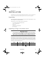
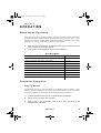
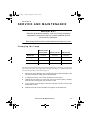
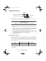
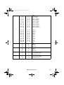
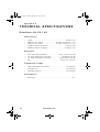
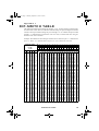
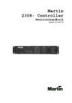
812C.fm Page 1 Monday, September 3, 2001 4:23 PM
RoboScan 812
user manual
812C.fm Page 2 Monday, September 3, 2001 4:23 PM
© 1998, 1999 Martin Professional A/S, Denmark.
All rights reserved. No part of this manual may be
reproduced, in any form or by any means, without
permission in writing from Martin Professional A/S,
Denmark.
Printed in Denmark.
P/N 35000052, Rev. C
812C.fm Page 3 Monday, September 3, 2001 4:23 PM
section 1
INTRODUCTION
Thank you for selecting the Martin RoboScan 812. It is designed and built to be bright, reliable and easy to use. With proper setup and maintenance, the RoboScan 812 will provide
years of trouble-free operation.
Read this manual before operating the RoboScan 812. Safety hazards or damage to the fixture may occur if it is handled or operated incorrectly. For your protection and other’s,
always follow the safety precautions listed below and observe the warnings in this manual
and printed on the fixture. If you have questions about how to operate and service the fixture, please contact your Martin dealer for assistance before proceeding. Refer any service
not described in this manual to a qualified Martin technician.
This manual covers the RoboScan 812 with software version 2.8 or higher. The latest information on the RoboScan 812 is always available from your dealer and the Martin web site
at http://www.martin.dk.
S A F E T Y P R E C AU T I O N S
•
The RoboScan 812 is NOT for domestic use.
•
For protection against dangerous electric shock, always ground (earth) the fixture
electrically, use only a source of AC power that complies with local building and electrical codes, and do not expose the fixture to rain or moisture. Disconnect the fixture
from AC power before removing any cover or part.
•
Disconnect the fixture from AC power if the lamp blows. Allow the fixture to cool for
10 minutes before installing a new lamp.
•
Do not illuminate surfaces within 30 cm (12 inches) of the fixture.
•
Do not place filters or other objects over the lens or mirror.
•
Keep all combustible materials (for example fabric, wood, paper) at least 10 cm (4
inches) away from the fixture. Keep flammable materials well away from the fixture.
•
Provide a minimum clearance of 10 cm (4 inches) around the fan and air vent.
•
Do not operate the fixture if the ambient temperature exceeds 40° C (104° F).
•
When suspending the fixture above ground level, verify that the structure can hold at
least 10 times the weight of all installed devices and secure the fixture with an
approved safety cable. Block access below the work area whenever installing or
removing the fixture.
•
For protection against dangerous UV radiation, never operate the fixture with missing
and/or damaged covers or lenses installed and do not stare into the light. Replace any
broken or cracked component immediately.
•
Refer all service to a qualified technician.
I nt r o du c t i on
3
812C.fm Page 4 Monday, September 3, 2001 4:23 PM
Features
4
•
150 watt discharge lamp
•
11 dichroic colors plus white
•
11 gobos plus open and blackout
•
175° pan movement
•
83° tilt movement
•
Variable speed control on all functions
•
Split color and gobo effects
•
Variable strobe up to 7 Hz
•
Remote lamp on/off (with Martin-protocol controllers)
•
Coated precision optics
•
Adjustable focus
•
Controllable via Martin and DMX-512 controllers
•
Preprogrammed stand-alone operation
•
Music trigger using built-in microphone
•
Power factor correction for low current consumption
•
Efficient fan cooling
•
Overheating protection
Ro bo Sc a n 8 1 2
812C.fm Page 5 Monday, September 3, 2001 4:23 PM
section 2
INSTALLATION
The RoboScan 812 is delivered fully adjusted from the factory; only a few setup steps are
necessary. Please follow them carefully to get the most out of your new equipment.
Unpacking
The packing material is carefully designed to protect the fixture during shipment - always
use it or a flight case to transport the fixture.
The RoboScan 812 comes complete with the following items:
•
150 W Martin Metal Halide discharge lamp
•
5 meters XLR-XLR cable
•
mains cable
•
mounting bracket and hardware
•
this user manual
I n s t a l l i n g a P l u g o n t h e Pow e r C o rd
WA RN IN G !
For protection from dangerous electric shock, the fixture
must be grounded (earthed). The AC supply shall be fitted
with a fuse or circuit breaker and ground-fault protection.
The RoboScan 812 is delivered without a plug on the power cord. Following the manufacturer’s instructions, install an approved 3-prong grounding-type plug that fits your supply.
Connect the wires to the pins as listed below. The table shows some possible pin identification schemes; if the pins are not clearly identified, or if you have any doubts about proper
installation, consult a qualified electrician.
Wire
Pin
Marking
Screw color
brown
live
“L”
yellow or brass
blue
neutral
“N”
silver
yellow/green
ground
Installa tion
green
5
812C.fm Page 6 Monday, September 3, 2001 4:23 PM
Checking voltag e and frequency settings
The RoboScan 812 voltage setting must be within 5% of the AC mains supply. The voltage
setting may be adjusted to local conditions. The frequency (50 or 60 Hz depending on
model), however, must match your supply. Check the settings printed on the label near the
mains input. See page 13 to change the voltage setting if necessary.
Releasing the Pan/Tilt Lock
The pan/tilt assembly (9) floats in a special rubber mount to reduce noise when operating
the pan and tilt motors. In order to protect the pan/tilt assembly from damage during shipment, it is secured with two plastic straps and a locking thumbscrew. These must be
removed before using the RoboScan!
It is strongly recommended that the pan/tilt assembly be locked for transportation by replacing the thumbscrew in position A over the pan/tilt assembly.
1.
Cut and remove the two plastic straps.
2.
Remove the thumbscrew over the pan/tilt assembly and store it in the
threaded hole, labelled B, on the pan/tilt plate.
3.
Carefully remove the surface protection foil and warning notice from the
mirror.
Installing the Mounting Bracket
Use the 11 mm hole in the center of the mounting bracket to fasten a clamp (not included),
or to permanently bolt the fixture in place, with a grade 8.8 (minimum) M10 bolt and lock
nut. For safety, verify that the structure can support at least 10 times the weight of all
installed fixtures, clamps, cables, auxiliary equipment, etc., and always use an approved
means of secondary attachment such as a safety cable to prevent falls.
The mounting bracket may also be used as a floor stand.
6
1.
Insert the two black plastic hand wheels into the bracket holes.
2.
Place a plastic spacer on each hand wheel, between the bracket and the
casing, and screw the hand wheels into the fixture.
3.
Turn or tilt the RoboScan to the desired position and tighten the hand
wheels.
Ro bo Sc a n 8 1 2
812C.fm Page 7 Monday, September 3, 2001 4:23 PM
Setup for Controller Operation
Connect the Serial Link
The RoboScan 812 may be used with DMX and Martin protocol controllers. The RoboScan
812’s XLR connections are configured for Martin protocol controllers such as the 3032.
When connecting a RoboScan 812 to any DMX-standard device, you must swap pins 2 and
3 with a phase-reversing cable.
1.
Connect the controller’s data output to the RoboScan 812’s input (2). If using
a Martin-standard controller, use a direct 3-pin to 3-pin cable such as the one
provided. If using a DMX controller, use a phase-reversing cable, either 3-pin
to 3-pin, or 5-pin to 3-pin, depending on the output of the controller.
2.
Continue the link: connect the output (1) of the fixture closest to the controller to the input of the next fixture. Use a direct cable when connecting
same-standard fixtures. Use a phase-reversing cable only when connecting a DMX-standard fixture to a Martin fixture with pin 2 hot. Up to 32 fixtures may be connected on a serial link.
3.
Insert a male 120 Ω XLR termination plug in the output of the last fixture
on the link. The termination plug is simply a 3-pin male XLR plug with a
120 Ω resistor soldered between pins 2 and 3. The termination plug is
required for error-free communication.
3-pin to 3-pin
Phase Reversing
Cable
Connections
5-pin to 3-pin
Phase Reversing
Cable
Connections
3-pin to 5-pin
Phase Reversing
Cable
Connections
Male
Female
Male
Female
Male
Female
1
2
3
1
2
3
1
2
3
4
5
1
2
3
1
2
3
1
2
3
4
5
P/N 11820006
P/N 11820003
P/N 11820002
Set the Address
When using the RoboScan 812 with a controller, you must set the DIP-switch (3) to the start
channel, also known as the address, which is the first channel the controller uses to send
instructions to the RoboScan 812.
For independent control, each fixture must have its own address and control channels. Two
or more RoboScan 812s may have the same address; however, they will receive the same
instructions and behave identically.
Installa tion
7
812C.fm Page 8 Monday, September 3, 2001 4:23 PM
Martin mode: The RoboScan 812 uses 1 channel to communicate with the controller. The
address may be any channel between 1 and 32.
DMX mode: The RoboScan 812 may be operated in tracking or vector mode; see the DMX
protocol for details. It uses 5 consecutive DMX channels in tracking mode and 7 consecutive DMX channels in vector mode. The factory default is tracking mode. The address may
be any channel up to 508 within the controller’s range (506 if 7 channels are used).
1
2
3
4
5
6
7
8
9
10
11
12
13
14
15
16
17
18
19
20
Example: 4 RoboScans using tracking mode (5 channels) may be addressed as follows:
812 No. 1
812 No. 2
Address: 1 Address: 6
812 No. 3
Address: 11
812 No. 4
Address: 16
Use the following procedure to set a Martin or DMX address.
1.
Select an available address within the controller’s range.
2.
Look up the DIP-switch setting on page 19. You can also calculate it by
subtracting pin values until the total of the values equals the address.
Start with the highest pin value that can be subtracted and work down
until there is no remainder. The table below shows the pin values.
3.
Set the DIP-switch (3) by flipping ON the pins found in step 2.
pin
1
2
3
4
5
6
7
8
9
10
value
1
2
4
8
16
32
64
128
256
OFF
.
Example: Channel 6
Pins 2 and 3 ON
Example: Channel 82
Pins 2, 5 and 7 ON
channel
- value of pin 3
6
-4
channel
- value of pin 7
82
- 64
remainder
- value of pin 2
2
-2
remainder
- value of pin 5
18
- 16
remainder
0
remainder
- value of pin 2
2
-2
remainder
On
On
1 2 3 4 5 6 7 8 9 10
8
Ro bo Sc a n 8 1 2
1 2 3 4 5 6 7 8 9 10
0
812C.fm Page 9 Monday, September 3, 2001 4:23 PM
section 3
OPERATION
Stand-Alone Operation
The RoboScan 812 may be operated without a controller in stand-alone mode. In this mode,
the fixture performs a random sequence that is triggered by the beat of the music or automatically at a set speed. The DIP-switch must be set to the desired stand-alone mode before
applying power. Settings for the different modes are shown below.
1.
With the fixture powered off, set the DIP-switch (3) for the desired mode.
Pins not listed must be switched off.
2.
Apply power to the RoboScan 812 to run the sequence.
Stand-Alone Modes
Description
Pins Switched ON
Random sequence, wide pan/tilt, auto trigger
2, 10
Random sequence, wide pan/tilt, music trigger
1, 2, 10
Random sequence, narrow pan/tilt, auto trigger
2, 3, 10
Random sequence, narrow pan/tilt, music trigger
1, 2, 3, 10
Lamp ON
8, 10
Lamp OFF
7, 10
Adjustment sequence (for service use and lamp adjustment)
5, 10
L.E.D. chase auto-trig (for service use only)
4, 10
L.E.D. chase music-trig (for service use only)
1, 4, 10
Controller Operation
Getting Starte d
The RoboScan 812 may be used with DMX-512 and Martin protocol controllers; it automatically determines which protocol is in use. Protocol auto-detection can be reactivated if
necessary by switching on all ten DIP-switches and then resetting the address.
1.
Connect the RoboScan 812 to the controller and set the address.
2.
Switch on and configure the controller.
3.
Apply power to the RoboScan. After a short reset procedure it will
respond to the controller.
Op era t io n
9
812C.fm Page 10 Monday, September 3, 2001 4:23 PM
Controllable Effects
Lamp
After switching on the RoboScan 812, the lamp remains off until a “lamp on” command is
sent from the controller. If using a Martin protocol controller, the lamp may also be turned
off via the controller. This feature is not implemented in the DMX protocol - to turn off the
lamp you must power off the fixture.
It's important to note that the lamp is a cold restrike type: it must be cold before striking is
possible. The lamp must cool for approximately 5 minutes before it can be turned on again.
Pan/Tilt
The moving mirror allows you to pan the beam 175° and tilt it 83°. Movement speed may
be adjusted with the controller fade time (DMX tracking mode and Martin controllers) or
on a separate channel (DMX vector mode).
Color Wheel
The RoboScan 812 has 13 positions on the color wheel: 11 with saturated dichroic colors,
open white, and blackout. The wheel can be positioned between 2 colors to split the beam.
The speed of the color and gobo wheels may be adjusted with the controller fade time
(DMX tracking mode and Martin controllers) or on a separate channel (DMX vector mode).
Selecting color strobe causes the color wheel to change between any 2 adjacent colors or
between white and black. The strobe speed is variable.
Gobos
The RoboScan 812 has 11 gobos on the gobo wheel plus open and blackout. Selecting gobo
strobe causes the gobo wheel to change between any 2 adjacent gobos or between full open
and black. The strobe speed is variable.
Random Sequence
The RoboScan 812 may be set to perform a preprogrammed sequence with automatic or
music trigger.
Focus
Focus may be adjusted manually from 1 meter to infinity by turning the threaded lens barrel
(7). Screwing the lens in increases the focus distance; screwing it out decreases the distance
at which the image is focused.
10
Ro bo Sc an 8 12
812C.fm Page 11 Monday, September 3, 2001 4:23 PM
section 4
SERVICE AND MAINTENANCE
WARNING!
Read the procedures carefully. If you do not feel completely
competent to perform the service, consult qualified service
personnel for assistance.
Disconnect the fixture from power before removing any cover.
Changing the Lamp
Martin 150 W
Metal Halide
Osram HTI 150
GE CSS 150
97010107
97010108
97010104
Average Life
2000 h
750 h
1000 h
Color Temp.
5000K
6500K
5000K
Output
900 lm
1200 lm
900 lm
Martin P/N
The three lamps shown above may be used in the RoboScan 812. Installing any other lamp
may damage the fixture. The lamp holder is adjusted at the factory; if further alignment is
necessary, the procedure is described on page 12.
1.
Remove the 3 thumbscrews (10) securing the lamp-socket assembly to the
rear of the RoboScan. Gently pull out the assembly.
2.
If changing the lamp, remove the old lamp from the socket.
3.
Holding the new lamp in a clean cloth (do not touch the glass), carefully
insert it firmly and squarely into the lamp socket.
4.
If your fingers touch the glass, clean the bulb with a clean, lint-free cloth
wetted with alcohol.
5.
Replace the lamp-socket assembly and tighten the thumbscrews.
Se rvice and Maintenance
11
812C.fm Page 12 Monday, September 3, 2001 4:23 PM
Adjusting the Lamp
The RoboScan 812 comes fully adjusted from the factory, however, readjustment of the
lamp may improve performance. The lamp is adjusted by turning the 3 screws (11) on the
lamp access plate (12). Turning these clockwise pulls the lamp back towards the rear and
vice versa. Keep adjustments small to avoid pulling the lamp so far off center that it hits the
reflector.
1.
Set up the RoboScan 812 so that you can access the lamp-access plate (12)
and, if adjusting the lamp without a controller, the DIP-switch (3).
2.
With controller: Turn on the RoboScan 812 and allow the lamp to warm
up for 5 minutes. From the controller, select white light with the open
gobo and position the beam on a flat, white surface. Focus the beam.
Without controller: Flip DIP-switch pins 1, 5 and 10 on. Flip all other
pins off. Apply power to the RoboScan 812. After it has reset, the fixture
produces a white light with an open gobo for adjustment purposes. Wait
approximately 5 minutes for the lamp to reach full brightness. Position
the fixture and/or mirror so the light shines on a flat, white surface and
focus the beam.
12
3.
If there is an off-center “hot spot,” the lamp is not centered in the reflector. Pull the hot spot into the center of the field with small adjustments of
one or more of the screws (11). Note: the Martin Metal Halide lamp is
nearly as large as the reflector opening - very little side to side adjustment is possible or necessary.
4.
If the light is significantly brighter in the center of the field than it is at the
edge, the lamp is too far forward in the reflector. Pull the lamp in by turning all three screws clockwise 1/4-turn at a time until the light is evenly
distributed.
5.
If the light is brighter around the edge than it is in the center, or if light
output is low, the lamp is too far back in the reflector. “Push” the lamp out
by turning the screws counterclockwise 1/4-turn at a time until the light is
bright and evenly distributed.
6.
If you have made large sideways adjustments, disconnect the fixture from
AC power, allow it to cool, and remove the lamp assembly to ensure that
the lamp is still placed squarely in the socket.
Ro bo Sc an 8 12
812C.fm Page 13 Monday, September 3, 2001 4:23 PM
DMX Mode Selection
PL11
6 5 4 3 2 1
7 channel vector mode
5 channel tracking mode
fan connector
jumper
The DMX mode is set with a jumper on the circuit board inside the unit. The factory default
is tracking mode. Follow the procedure below to change the mode.
WARNING!
Make sure the fixture is disconnected from AC power.
1.
Remove the cover (6) above the lamp. Remove the cover (8) above the circuit
board.
2.
Locate connector PL11 on the circuit board: refer to the label inside the
chassis. On one or two of the pins there is a black clip - a jumper - that
creates an electrical connection when placed over 2 pins.
3.
Place the jumper on pins 4 and 5 to enable 7-channel vector mode.
Remove the jumper to enable 5-channel tracking mode. You can store
the jumper by placing it sideways on one of the pins.
4.
Reassemble the fixture.
S e l e c t i n g Vo l t a g e
The voltage and frequency settings must match the local AC power supply! Operating at the
incorrect setting can result in poor light output, shortened lamp life, overheating and damage to the fixture. The factory setting is printed on the serial number label next to the mains
input. If the voltage is not within 5 percent of the local supply, then the ballast and transformer must be rewired.
Model
Selectable Voltages
Frequency
RoboScan 812 EU
230 V / 240 V / 250 V
50 Hz
RoboScan 812 US
100 V / 110 V / 120 / 220 V
50 or 60 Hz*
* The RoboScan 812 US may also be used with a 100 V, 50 Hz supply when wired for 120
V, 60 Hz operation.
Se rvice and Maintenance
13
812C.fm Page 14 Monday, September 3, 2001 4:23 PM
WARNING!
Make sure the fixture is disconnected from AC power.
RoboScan 812 US
1.
Remove the cover above the lamp. (6)
2.
Remove the cover (8) above the circuit board.
3.
Locate the connection block next to the circuit board. Right beside it is a
label indicating the proper terminal for each voltage.
4.
With a small screwdriver, loosen the screw in the terminal that holds the
BROWN wire. Remove the brown wire. Tighten the screw. Note: The
BLACK wire must always be connected to the 220 V terminal.
5.
Loosen the screw for the terminal closest to the supply voltage and insert
the BROWN wire. Tighten the screw.
6.
Remove the end plate (5) to access the ballast.
7.
To set the frequency, move the GREY wire on the ballast to the “230-50”
(50 Hz) or “230-60” (60 Hz) terminal. The wire is released and locked by
inserting a small screwdriver in the square hole next to the terminal and
prying back the spring.
8.
Tug lightly on the GREY wire to make sure that it is connected securely.
9.
Reassemble the unit before connecting to AC power.
RoboScan 812 EU
14
50 Hz AC Supply
Transformer
Setting
Ballast
Setting
218 - 234 V
230 V
230 V
235 - 240 V
230 V
240 V
241 - 244 V
250 V
240 V
245 - 260 V
250 V
250 V
1.
Remove the cover above the lamp. (6)
2.
Remove the cover (8) above the circuit board.
3.
Move the BROWN transformer wire to the transformer setting shown
above. Do not move the WHITE and BLUE wires from terminal 1.
4.
Remove the end plate (5) to access the ballast.
Ro bo Sc an 8 12
812C.fm Page 15 Monday, September 3, 2001 4:23 PM
5.
Remove the GRAY wire from the ballast terminal: insert a screwdriver in
the small hole under the terminal and release the spring with a clockwise
turn.
6.
Open the spring for the correct ballast terminal and insert the GRAY wire.
The terminals are marked on the side of the ballast.
7.
Reassemble the unit before connecting to AC power.
Replacing the Fuse
The holder for the main fuse is built in to the mains input socket (4). If the fuse blows
repeatedly, the fixture requires servicing by a qualified technician. Never replace the fuse
with one of a different rating!
1.
Unplug the mains cable from the input socket.
2.
Pry open the fuse holder and remove the fuse.
3.
Replace the fuse with one of the same type and rating. The fuse rating is
listed on serial number label on the end plate.
4.
Close the fuse holder and replace the mains cable.
Se rvice and Maintenance
15
812C.fm Page 16 Monday, September 3, 2001 4:23 PM
appendix a
DMX 512 PROTOCOL
The RoboScan 812 supports tracking and vector mode. In tracking mode, speed is determined by the controller’s fade time. In vector mode, speed is determined by a value programmed on a separate DMX channel. For smooth movement in vector mode, the
controller’s fade time must be set to 0, i.e., the position must bump from the current value to
the next. If the RoboScan 812 is set to run vector mode, tracking mode can be enabled by
programming the speed channels to 0.
DMX
Channel
1
DMX
Values
Percent
Effect
0 - 10
11 - 74
75 - 138
139 - 170
171 - 202
203 - 235
236 - 255
0-4
4 - 29
29 - 54
55 - 67
67 - 79
80 - 92
93 - 100
Strobe, SA, Reset, Lamp ON
No strobe
Gobo strobe (fast ! slow)
Color strobe (fast ! slow)
Remote Auto trig
Remote Music trig
Reset fixture
Lamp power ON
0 - 15
15 - 30
30 - 45
45 - 60
60 - 75
75 - 90
90 - 105
105 - 120
120 - 135
135 - 150
150 - 165
165 - 180
0-6
6 - 12
12 - 18
18 - 24
24 - 29
29 - 35
35 - 41
41 - 47
47 - 53
53 - 59
59 - 65
65 - 71
Color
black ! white
white ! color 1
color 1 ! color 2
color 2 ! color 3
color 3 ! color 4
color 4 ! color 5
color 5 ! color 6
color 6 ! color 7
color 7 ! color 8
color 8 ! color 9
color 9 ! color 10
color 10 ! color 11
180 - 184
185 - 189
190 - 194
195 - 199
200 - 204
205 - 209
210 - 214
215 - 219
220 - 224
225 - 229
230 - 234
235 - 239
240 - 255
71 - 72
73 - 74
75 - 76
76 - 78
78 - 80
80 - 82
82 - 84
84 - 86
86 - 88
88 - 90
90 - 92
92 - 94
94 - 100
color 11
color 10
color 9
color 8
color 7
color 6
color 5
color 4
color 3
color 2
color 1
white
black
2
16
Ro bo Sc an 8 12
812C.fm Page 17 Monday, September 3, 2001 4:23 PM
0 - 15
15 - 30
30 - 45
45 - 60
60 - 75
75 - 90
90 - 105
105 - 120
120 - 135
135 - 150
150 - 165
165 - 180
0-6
6 - 12
12 - 18
18 - 24
24 - 29
29 - 35
35 - 41
41 - 47
47 - 53
53 - 59
59 - 65
65 - 71
Gobo
closed ! open
open ! gobo 1
gobo 1 ! gobo 2
gobo 2 ! gobo 3
gobo 3 ! gobo 4
gobo 4 ! gobo 5
gobo 5 ! gobo 6
gobo 6 ! gobo 7
gobo 7 ! gobo 8
gobo 8 ! gobo 9
gobo 9 ! gobo 10
gobo 10 ! gobo 11
180 - 184
185 - 189
190 - 194
195 - 199
200 - 204
205 - 209
210 - 214
215 - 219
220 - 224
225 - 229
230 - 234
235 - 239
240 - 255
71 - 72
73 - 74
75 - 76
76 - 78
78 - 80
80 - 82
82 - 84
84 - 86
86 - 88
88 - 90
90 - 92
92 - 94
94 - 100
gobo 11
gobo 10
gobo 9
gobo 8
gobo 7
gobo 6
gobo 5
gobo 4
gobo 3
gobo 2
gobo 1
open
closed
0
127
255
0
50
100
Pan
Max Left
Neutral
Max Right
0
127
255
0
50
100
Tilt
Max Up
Neutral
Max Down
6
0
1 - 255
0
1 - 100
Movement Speed (vector mode only)
Tracking mode enabled
Speed (fast ! slow)
7
0
1 - 255
0
1 - 100
Color / Gobo speed (vector mode only)
Tracking mode enabled
Speed (fast ! slow)
3
4
5
DMX 512 Protocol
17
812C.fm Page 18 Monday, September 3, 2001 4:23 PM
appendix b
T E C H N I C A L S P E C I F I C AT I O N S
RoboScan 812 EU / US
Dimensions:
•
•
•
•
•
Length:.........................................................................................436 mm (17.2")
Height incl./excl. bracket:..................................267 mm / 165 mm (10.5" / 6.5")
Width incl./excl. bracket:.....................................245 mm / 190 mm (9.6" / 7.5")
Weight incl. bracket (EU model):................................................9.4 Kg (20.7 lb)
Weight incl. bracket (US model): ..............................................10.5 Kg (23.1 lb)
Electrical
•
•
•
•
Power and current consumption: .............................. 170 W, 1 A at 230 V, 50 Hz
AC voltage and frequency (EU model): ............................ 230/240/250 V, 50 Hz
AC voltage and frequency (US model): .....................100/110/120/220 V, 60 Hz
Fuse:..............................................................................3.15 AT (EU) / 4AT (US)
Compatible Lamps
•
•
•
Martin Metal Halide 150 (standard) .............................................. P/N 97010107
Osram HTI 150.............................................................................. P/N 91010108
GE Lighting CSS 150 .................................................................... P/N 91010104
Photometric
•
18
Beam angle: ..................................................................................................15.5°
Ro bo Sc an 8 12
812C.fm Page 19 Monday, September 3, 2001 4:23 PM
appendix c
D I P - S W I T C H TA B L E
This table shows DIP-switch settings for channels 1- 511. To find a setting, locate the channel in the table. Follow the row to the left to find the settings for pins 1 through 5; follow the
column to the top to find the settings for pins 6 through 9. A “0” indicates the pin is turned
off and a “1” indicates the pin is turned on. Pin 10 is always switched OFF when using the
RoboScan 812 with a controller.
Example: The table shows the setting for channel 212 is 00101 for pins 1 - 5 and 0110 for
pins 6 - 9. Pins 3, 5, 7, and 8 are set to on; pins 1, 2, 4, 6, 9, and 10 are set to off.
DIP-Switch Setting
#1
0
1
0
1
0
1
0
1
0
1
0
1
0
1
0
1
0
1
0
1
0
1
0
1
0
1
0
1
0
1
0
1
0 = OFF
1 = ON
#2 #3 #4
0 0 0
0 0 0
1 0 0
1 0 0
0 1 0
0 1 0
1 1 0
1 1 0
0 0 1
0 0 1
1 0 1
1 0 1
0 1 1
0 1 1
1 1 1
1 1 1
0 0 0
0 0 0
1 0 0
1 0 0
0 1 0
0 1 0
1 1 0
1 1 0
0 0 1
0 0 1
1 0 1
1 0 1
0 1 1
0 1 1
1 1 1
1 1 1
#5
0
0
0
0
0
0
0
0
0
0
0
0
0
0
0
0
1
1
1
1
1
1
1
1
1
1
1
1
1
1
1
1
#9
#8
#7
#6
0
0
0
0
0
0
0
1
0
0
1
0
0
0
1
1
0
1
0
0
0
1
0
1
0
1
1
0
0
1
1
1
1
0
0
0
1
0
0
1
1
0
1
0
1
0
1
1
1
1
0
0
1
1
0
1
1
1
1
0
1
1
1
1
1
2
3
4
5
6
7
8
9
10
11
12
13
14
15
16
17
18
19
20
21
22
23
24
25
26
27
28
29
30
31
32
33
34
35
36
37
38
39
40
41
42
43
44
45
46
47
48
49
50
51
52
53
54
55
56
57
58
59
60
61
62
63
64
65
66
67
68
69
70
71
72
73
74
75
76
77
78
79
80
81
82
83
84
85
86
87
88
89
90
91
92
93
94
95
96
97
98
99
100
101
102
103
104
105
106
107
108
109
110
111
112
113
114
115
116
117
118
119
120
121
122
123
124
125
126
127
128
129
130
131
132
133
134
135
136
137
138
139
140
141
142
143
144
145
146
147
148
149
150
151
152
153
154
155
156
157
158
159
160
161
162
163
164
165
166
167
168
169
170
171
172
173
174
175
176
177
178
179
180
181
182
183
184
185
186
187
188
189
190
191
192
193
194
195
196
197
198
199
200
201
202
203
204
205
206
207
208
209
210
211
212
213
214
215
216
217
218
219
220
221
222
223
224
225
226
227
228
229
230
231
232
233
234
235
236
237
238
239
240
241
242
243
244
245
246
247
248
249
250
251
252
253
254
255
256
257
258
259
260
261
262
263
264
265
266
267
268
269
270
271
272
273
274
275
276
277
278
279
280
281
282
283
284
285
286
287
288
289
290
291
292
293
294
295
296
297
298
299
300
301
302
303
304
305
306
307
308
309
310
311
312
313
314
315
316
317
318
319
320
321
322
323
324
325
326
327
328
329
330
331
332
333
334
335
336
337
338
339
340
341
342
343
344
345
346
347
348
349
350
351
352
353
354
355
356
357
358
359
360
361
362
363
364
365
366
367
368
369
370
371
372
373
374
375
376
377
378
379
380
381
382
383
384
385
386
387
388
389
390
391
392
393
394
395
396
397
398
399
400
401
402
403
404
405
406
407
408
409
410
411
412
413
414
415
416
417
418
419
420
421
422
423
424
425
426
427
428
429
430
431
432
433
434
435
436
437
438
439
440
441
442
443
444
445
446
447
448
449
450
451
452
453
454
455
456
457
458
459
460
461
462
463
464
465
466
467
468
469
470
471
472
473
474
475
476
477
478
479
480
481
482
483
484
485
486
487
488
489
490
491
492
493
494
495
496
497
498
499
500
501
502
503
504
505
506
507
508
509
510
511
DIP-Switch Table
19