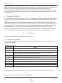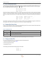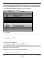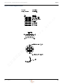
1
cn
w
.ig
yr
o.
Model 547
Model 548
w
w
Directional Sensors
Technical Reference and User Manual
北
京
诚
思
嘉
科
技
有
限
公
司
430 CPU Version
Applied Physics Systems
281 East Java Drive
Sunnyvale, CA. 94089 USA
Document Number: Rev 1.1_FEB2011
Models 547/548 - Technical Reference and User Manual
© 2011 Applied Physics Systems, Inc. — All Rights Reserved
All other brands or products mentioned are trademarks or registered trademarks of their respective
holders and should be treated as such.
Contact Information
Applied Physics Systems
281 East Java Drive
Sunnyvale, CA. 94089 USA
北
京
诚
思
嘉
科
技
有
限
公
司
w
w
w
.ig
yr
o.
cn
650.965.0500
Fax: 650.965.0404
Email: [email protected]
Web: www.appliedphysics.com
2
Rev 1.1_FEB2011
Models 547/548 - Technical Reference and User Manual
Contents
Sections
1 - ”Introduction” on page 4
2 - ”Description of the Equipment” on page 4
3 - ”System Specifications” on page 5
4 - ”Mechanical Features” on page 5
5 - ”Electrical Interface” on page 5
cn
6 - ”Computer Interface” on page 6
yr
o.
7 - ”Definition and Method of Calculation of the Orientation Sensor Angles” on page 15
8 - ”Figures” on page 18
.ig
Tables
Table 1, “547/548 System Specifications,” on page 5
w
Table 2, “Binary Constants,” on page 6
w
Table 3, “Floating Constants (frequently used),” on page 7
w
Table 4, “Output Data Format,” on page 8
Table 5, “Baud Rate Settings,” on page 9
司
Table 6, “Autosend Modes,” on page 9
Table 7, “Output Data Averaging and Filtering,” on page 9
公
Table 8, “Binary Data Packets for Sensor and Angle Modes,” on page 12
限
Table 9, “Dip Angle and Azimuth Accuracy,” on page 14
有
Figures
技
Figure 1 - ”547/548 Micro Orientation Sensor Outline Drawing” on page 18
Figure 2 - ”Connection Diagram for the 547” on page 19
北
京
诚
思
嘉
科
Figure 3 - ”Coordinate System of 547/548” on page 20
Rev 1.1_FEB2011
3
Models 547/548 - Technical Reference and User Manual
Introduction
1 - Introduction
This manual describes the model 547 Directional Sensor. This system is designed to enable high accuracy measurement of the inclination, roll (or toolface), and azimuth orientation angles in borehole environments.
2 - Description of the Equipment
yr
o.
cn
The model 547 Directional Sensor contains both a 3-axis fluxgate magnetometer and a 3-axis accelerometer. The
combination of these two sensor systems enables the inclination, roll and azimuth angles of the 547 reference frame to
be determined. Inclination and roll angles are determined from the accelerometer subsystem, which measures the pull
of gravity. After inclination and roll are known, the magnetometer subsystem is used to determine system azimuth
angle. Knowledge of the inclination and roll angles enable determination of the horizontal components of the earth's
local magnetic field; this information defines the azimuth angle.
.ig
The 547 system contains a microprocessor and 8 channels of 16-bit analog to digital conversion. Six channels are
assigned to the magnetometer and accelerometer outputs. One channel provides temperature data from an internal
thermometer and one channel is configured to measure the system input voltage.
w
w
The 547 communicates with the outside world over a 3-wire serial bidirectional TTL level data link. An autosend data
mode is included in the 547 software. When this mode is active, data is repeatedly sent out the system serial port after
power is applied.
司
w
The 547 system accelerometers are calibrated by placing the system in a precision rotation fixture and systematically
changing the system orientation in the earth's gravitational field. The 547 system magnetometers are calibrated by
placing the system in a precision 3-axis Helmholtz coil system which enables the application of known magnetic fields
to the system. Both the rotation fixture and Helmholtz coil have alignment pins and reference surfaces which mate to
the 547 alignment pins. System calibration can be performed over the two temperature ranges:
公
• 0° to 70°C
限
• 0° to 125°C
北
京
诚
思
嘉
科
技
有
When the system is calibrated over a temperature range, data is read from the system at temperature intervals
between the minimum and maximum temperature specification. For instance, for calibration over the interval of 0
to125°C, data is read at 25°C increments between 0 and 125°C. The data taken at each temperature includes scale,
offset and sensor alignment data. The recorded data is then used to create a look up table for scale offset and alignment corrections. This table is downloaded into the 547 internal EEROM memory where it can be accessed by the
system internal microprocessor. Corrections to the measured sensor data can then be made by the internal microprocessor system before data is transmitted.
4
Rev 1.1_FEB2011
System Specifications
Models 547/548 - Technical Reference and User Manual
3 - System Specifications
Table 1. 547/548 System Specifications
Angular Accuracy
Azimuth
±1.2º
Inclination
±0.4º
Temperature Range
0° to 70°C
Option 2
cn
Option 1
0° to +125°C
Power
5V to 12V @ 50mA
yr
o.
Input Voltage Range
Physical
1.00" OD x 10.5" length (25mm x 267mm)
Weight
1.25 lbs.
Shock
1000G 1ms half sine wave
Vibration
20G rms, 50-500Hz
w
Digital Interfaces
.ig
Size
TTL/CMOS
Baud Rate
User programmable up to 9600 baud
Protocol
User selectable ASCII or binary
w
司
Connectors
w
Logic Level
547 Connector
MDM9SH003P (ITT Cannon)
MDM9PH003L (ITT Cannon)
有
4 - Mechanical Features
限
公
Mating Connector
嘉
科
技
Figure 1 shows an outline drawing of the 547 System. The orientation of the X, Y and Z axes of the 547 system is
shown at the bottom of Figure 1. The output polarity sense of the axes is such that a field increase in the direction of
the arrows shown in Figure 1 produces an increase in the voltage output for that axis. For example, if the X magnetometer is oriented so the X axis arrow points north in the northern hemisphere, then the X axis output voltage will be positive. If the X axis arrow is pointed down, the X axis accelerometer output will be positive. Definition of the orientation
angles is given in section 7 - ”Definition and Method of Calculation of the Orientation Sensor Angles” on page 15.
诚
思
The orientation of the 547 sensor in the drillstring should be such that the X axis is pointed downhole. In this orientation, inclination will be 0° when drilling vertically downhole.
京
5 - Electrical Interface
北
Electrical connection to the 547 is made by means of a 9 pin MDM type connector. The function of the pins on this connector is shown in Figure 2. The 547 System powers from a single input voltage ranging from 5V to to 12V.
The serial communications interface to the 547 is provided by the serial in and serial out lines as shown in Figure 2.
An external computer communicates with the 547 on the serial in line and replies from the 547 are transmitted out on
the serial out line. The serial in and serial out pins operate at TTL/CMOS levels and are normally set to operate at 9600
baud with one stop bit and no parity. The user can change the baud rate by changing the system byte configuration
constants as described in the following section.
Two communication protocols are available: 1) ASCII and 2) BINARY. These are both described in section 6 - ”Computer Interface” on page 6. The ASCII protocol is based upon sending ASCII characters to the 547 to obtain data. The
reflected data is also sent out as an ASCII data stream complete with carriage returns and line feeds so that it can be
Rev 1.1_FEB2011
5
Computer Interface
Models 547/548 - Technical Reference and User Manual
easily displayed on a PC video terminal (provided a TTL to RS232 conversion is made by the user). The binary PC
protocol is used for high-speed computer-to-computer interchange. In this case, one byte is sent to request data. The
547 then responds with a multi-byte data packet containing the desired data plus header and checksum.
The system internal constants include a number of byte and floating constants. Generally, byte constants are used to
control the system operating modes. Floating constants are employed to scale the output data and correct it for temperature variations.
6 - Computer Interface
yr
o.
cn
The computer interface of the 547 System is a TTL level serial interface. In the standard configuration, data is transmitted to the 547 on pin 1 and transmitted out of the 547 on pin 2. The default baud rate is 9600 with one stop bit and no
parity.
.ig
In order to communicate with an external personal computer (PC), the TTL levels of the 547 must be shifted to the
RS232 levels used by the serial ports on all PCs. TTL levels generally are +5V (mark) and 0v (space) whereas RS232
levels are generally -5 to -12V (mark) and +5 to +12V (space). Integrated circuits such as the Max 232 (Maxim Integrated Products) or the LT1019 (Linear Technology) are suitable for constructing an RS232 to TTL interface.
司
In the above messages, the x’s represent the unit serial number.
w
S/Nxxxx
3.72 BowDip
w
APS:
Ver:
w
The best way to determine if communication with the 547 has been established is to observe the presence of the 547
sign on message that is transmitted at 9600 baud when power is turned on. The sign on message for the 547 is:
公
6.1 - 547 Internal Constants
限
The operating characteristics of the 547 are controlled by the value of internal binary constants. Table 2 shows the
most important constants.
有
Table 2. Binary Constants
技
Binary Constant
Function
Enables echoing when non zero.
01
Enables autosend upon power up when = 5A.
02
Enables sensor A/D count output when zero, sensor output (in Gauss and Gees) when =2 and angle output (roll,
inclination, azimuth) when =3 and Alternate labels (ROLL: PITCH: HEAD:).
05
Controls sending of power up sign on message (default=0, message enabled).
思
嘉
科
00
08
京
10
诚
09
Sets power on mode (e.g., 10 enables ASCII autosend upon power up).
北
23
35
Baud rate lock (must be =5A if any baud rate other than 9600 is used).
Sets baud rate.
Sets up averaging of the output.
Sets delay between transmissions in autosend mode.
In order to change the internal system binary constants, a write enable command must first be issued. This is:
0l
<CR>
Where 0 is zero, 1 is the letter 1 and <CR> is a carriage return.
6
Rev 1.1_FEB2011
Computer Interface
Models 547/548 - Technical Reference and User Manual
When this command is sent to the 547, it will respond with the reply
enabled!
To write binary constant 02=03, the command
0WC02b03
<CR>
(0WriteConstant02binary03) is issued. After receiving this and acting upon it, the 547 will respond with the reply
cn
done
yr
o.
The reading of internal constants can be accomplished by issuing the command
0SC02b <CR>
.ig
When this command is sent, the 547 will respond by sending the value of constant 02. Wildcards are also recognized.
The command OSC*b will cause the 547 to send the value of all internal binary constants.
w
for all constants
for constant 06
w
0SC*f <CR>
0SC06F <CR>
w
In addition to internal binary constants, the 547 also has a number of float constants. These are used to store the calibration data in the 547 Flash memory. These constants can be read by using the commands
司
The most important floating constants are shown in the following table.
Function
X Magnetometer Base Offset
05
Y Magnetometer Base Offset
06
Z Magnetometer Base Offset
07
X Accelerometer Base Offset
08
Y Accelerometer Base Offset
09
Z Accelerometer Base Offset
10
X Magnetometer Base Scale
11
Y Magnetometer Base Scale
技
科
嘉
思
诚
12
有
04
Z Magnetometer Base Scale
13
X Accelerometer Base Scale
14
Y Accelerometer Base Scale
15
Z Accelerometer Base Scale
北
京
限
Float Constant
公
Table 3. Floating Constants (frequently used)
Float constants 25 to 34 contain the system alignment coefficients. For example, float constant 26 contains data on
the magnetometer X sensor alignment in the Y direction. The 547 sensor is temperature compensated to insure that
the accuracy of the sensor is maintained over its intended temperature range. The temperature calibration data is
stored in the system Flash memory. This data can be accessed by using the following commands:
0st*b <CR>
0st*i <CR>
0st*f <CR>
Rev 1.1_FEB2011
Send temperature calibration table in binary format
Send temperature calibration table in integer format
Send temperature calibration table in floating format
7
Computer Interface
Models 547/548 - Technical Reference and User Manual
6.2 - ASCII Communication Mode
Communication is initiated when the external computer issues a command such as ASCII characters 0SD where 0 is a
zero. The characters 0SD stand for serial number 0 Send Data. When this command is issued, the 547 will respond
with a formatted output similar to the following:
MX:+0.20346 AX:-0.07852
MY:+0.23165 AY:+0.72136
MZ:+0.29525 AZ:+0.70226
TEMP: +28.148
.ig
MAGROLL: +198.24032
MAG: +0.43326
GRAV: +1.00101
DA: 55.893
w
ROLL: +35.17825
PITCH: +90.14559
HEAD: +26.76792
TEMP: +28.026
yr
o.
cn
When internal binary constant 02=02, the 547 is in sensor output mode and the above numbers represent the magnetometer X, Y and Z sensor outputs in Gauss (G) and the accelerometer outputs in Gees (g). When binary byte 02=03,
the 547 is in angle mode. When the 547 is in angle mode the response to a send data command has the following format:
w
where ROLL is gravity roll (or toolface), PITCH is inclination, HEAD is Azimuth, MAGROLL is magnetic roll, MAG is the
total magnetic field, GRAV is the total gravity field , and DA is the magnetic field dip angle.
w
6.3 - Changing Data Output Mode
公
司
The 547 can be configured to output in raw analog to digital (ADC) counts, sensor values or angles. Data output format
is determined by the value of binary constant 02 as follows:
限
Table 4. Output Data Format
Output Data Format
有
Binary 02 Value
Raw A/D Counts (Uncalibrated)
0x02
Sensor Outputs (Calibrated Accel and Mag)
0x03
Angular Outputs (Roll, Inc, Azimuth)
科
技
0x00
嘉
The nomenclature 0x in the above table indicates that the data following the 0x is in hex format.)
思
6.4 - Changing the Baud Rate
诚
The communications baud rate can be changed by using the following sequence:
1. Set binary constant 10 according to Table 5.
京
2. Set binary constant 09 to 0x5a.
北
3. Cycle power off and on.
The following commands illustrate setting the baud rate to 2400.
0l <CR>
0wc10b32 <CR>
0l <CR>
0wc09b5a <CR>
8
Rev 1.1_FEB2011
Computer Interface
Models 547/548 - Technical Reference and User Manual
When binary constant 09 is set to any value other than 0x5a, the system baud rate is 9600.
Byte 10 Value
300
0x35
1200
0x33
2400
0x32
4800
0x31
9600
0x30
yr
o.
Baud Rate
cn
Table 5. Baud Rate Settings
6.5 - Configuring for Autosend Mode
.ig
To configure the 547 for Autosend in either ASCII or Binary data format and in one of the three following output modes,
binary Constant 01 must to be set to 0x5A and binary constant 08 needs to be set in accordance with Table 6.
Send ASCII raw sensor data (un-calibrated Accel and Mag, etc.) continuously on power
up.
0x02
Send ASCII sensor data (calibrated Accel and Mag, etc.) continuously on power up.
0x03
Send ASCII angle data (computed Toolface, Inc and Azimuth, etc.) continuously on
power up.
w
0x00
司
0x10
Autosend Mode and Format
w
Binary 02 Value
公
Binary 08 Value
w
Table 6. Autosend Modes
Ignored when Byte 08≠0x10
Send Binary Data Continuously in Sensor Mode (calibrated Accel and Mag, etc.) on power
up.
0x12
Ignored when Byte 08≠0x10
Send Binary Data Continuously in Angle Mode (computed Inc and Az, etc.) on power up.
有
限
0x11
技
Note: If binary constant 35=0x10 is set, it will be to insert a small time delay between data packets (optional).
嘉
科
6.6 - Averaging and Filtering of Output Data
思
Averaging of the acquired data can be enabled by setting binary constant 23 according to Table 7.
Averages (n)
Averaging Times (sec)
0
1
0
2
2
0.6
4
4
1.32
8
8
2.64
10
16
5.28
20
32
10.62
40
64
21.30
北
诚
Binary Constant (23)
京
Table 7. Output Data Averaging and Filtering
The average time in the above table is approximately the time for the output to come within 37% of the final value.
Rev 1.1_FEB2011
9
Computer Interface
Models 547/548 - Technical Reference and User Manual
The above table assumes that the system analog to digital (A to D) converter low pass filter is set to the default of 30
Hz. For higher or lower filter settings the average time will proportionately higher or lower. For example if the A to D filter is set to 100 Hz, then the average time will be decreased by a factor of 3.3 so that for 64 averages the average time
will be 6.45 seconds.
Each data output of the 547 is a running average of the previous n data acquisitions where n is the value of binary constant 23. When a new data point is acquired, a new average is computed by dropping the oldest data point from the
average and adding the new data point.
cn
The maximum average is 64 samples. This average feature is useful for high vibration environments when the user
knows the attitude is changing slowly, but vibration produces a large amount of noise in the 547 output.
yr
o.
The A to D low pass filter -3 dB frequency can be set and displayed by use of the following set of commands:
To show current setting in Hz:
.ig
0sf<CR>
To set the frequency:
w
w
0l <CR>
0wfxx<CR
w
where xx= integer value from 10 to 100.
司
As with any filter operation, the lower the filter cutoff frequency, the slower the response. Any filter value of 10-100 Hz
is valid and the factory default setting is 30Hz. Use of filter values below 10Hz attenuates the signals significantly therefore filter values less than 10 Hz should not be used.
公
6.7 - Single Packet Binary Communication Modes
限
In addition to an ASCII communication mode, the 547 also has several binary communications modes:
技
有
Single data packet binary communications are initiated by an external computer by the issuance of a single byte command (e.g., ASCII 128). On some computers, these commands can be sent from a terminal emulator program by holding the control key down and typing the command number on the number pad on the right side of the keyboard.
Command Definition
ASCII 128
Send sensor data in binary format
ASCII 131
Send angle data in binary format
思
嘉
科
Command
京
诚
The 547, upon receiving one of these commands, responds by sending a binary data packet with one of the structures
described below.
北
Command <128> : Sends All Data in an encoded Binary Format.
The data is returned as:
<<Sent First <<<<<<<<<<<<<<<<<<<<<<<<<<<<<<<<<<<<<<<<<<Sent Last<<<<
<SOT><MX><AX><MY><AY><MZ><AZ><MT><V><Status><DATA CHECK SUM> <END>
8b 16b 16b 16b 16b 16b 16b 16b 16b 8b
8b
16b
• All Data is Sent most significant byte first.
10
Rev 1.1_FEB2011
Computer Interface
Models 547/548 - Technical Reference and User Manual
• <END>= 0x7FFF (should be unique in the data stream)
• <SOT>= 16Decimal or 10 Hex
• <Status>= a constant, 0x80, without meaning for 547 sensors
• <DATA CHECK SUM>= The lower 8 bits of the sum of all the bytes in the data area excluding <SOT> and <END>
• <MX>, <MY>, <MZ> = The Magnetometer data are in a two byte signed integer format encoded as the float value
times10000. (for example 0.2345 is encoded as 2345).
cn
• <AX>, <AY>, <AZ> = The Accelerometer data are in a two byte signed integer format encoded as the float value
times10000. (for example 0.2345 is encoded as 2345 ).
yr
o.
• <MT>= The Temperature is in a two byte signed integer format encoded as the float value times 100. (123.45 =
12345 )
.ig
• <V>= Downhole power voltage is in a two byte signed integer format encoded as the float value times 100. (8.4575 =
845.75)
Command <131> : Sends All Angle Data in an encoded Binary Format.
w
The data is returned as:
w
w
<<<<Sent First <<<<<<<<<<<<<<<<<<<<<<<<<<<<<<<<<<<<<<<<Sent Last<<<<
<SOT><Roll><MagRoll><Inclination><TotMag><Head><TotGrav><MT><V><Status><Data Check Sum><END>
8b 16b
16b
16b
16b
16b
16b
16b 16b
8b
8b
16b
• <END>= 0x7FFF (should be unique in the data stream)
公
• <SOT>= 16 Decimal or 10 Hex
司
• All Data is Sent most significant byte first.
限
• <Status>= a constant, 0x80, without meaning for 547 sensors
• <DATA CHECK SUM>= The lower 8 bits of the sum of all the bytes in the data area excluding <SOT> and <END>
有
• All angles are encoded by multiplying the angle by 10 (e.g., 123.56=1235.6)
技
• <TolMag> = Total magnetic field is in a two byte signed integer format encoded as the float value times10000. (For
example, 0.3929 is encoded as 3929).
科
• <TolGrav> = Total Gravity is in a two byte signed integer format encoded as the float value times10000. (For
example, 1.0047 is encoded as 10047).
嘉
• <MT> = The Temperature is in a two byte signed integer format encoded as the float value times 100. (123.45 =
12345 ).
诚
思
• <V> = Downhole power voltage is in a two byte signed integer format encoded as the float value times 100. ( 8.457
= 84.57 ).
京
6.8 - Autosend Binary Communication Mode
北
Standard binary protocol results in the transmission of data packets with the same structure as that described above
for the response to binary command 128. However, when in autosend mode, data packets are automatically and continuously sent out after power is applied. Standard autosend binary mode is selected by setting up the system binary
constants as follows:
• Binary constant 08=11 : Selects autosend continuously
• Binary constant 01=5a : Autosend enable
• Binary constant 35=10 : Inserts a small delay between data packets (optional)
Rev 1.1_FEB2011
11
Computer Interface
Models 547/548 - Technical Reference and User Manual
6.9 - Comparison of ASCII and Standard Binary Data Structures
Either ASCII or standard binary data transmission transmits the same data contents, but the ASCII data transmission
uses about 8 times more bytes than the binary transmission. The binary data packet is a much more efficient method
of sending data. In addition, binary data is often much easier to parse than ASCII data.
Table 8 shows the definition of the binary data packet for sensor mode and angle mode.
Table 8. Binary Data Packets for Sensor and Angle Modes
SOT = 0x10
Gravity Toolface (ROLL), MSB
Gravity Toolface (ROLL), LSB
Magnetic Toolface (MAGROLL), MSB
Magnetic Toolface (MAGROLL), LSB
Inclination (PITCH), MSB
Inclination (PITCH), LSB
Total Magnetic Field (MAG), MSB
Total Magnetic Field (MAG), LSB
Azimuth (HEAD), MSB
Azimuth (HEAD), LSB
Total Gravity (GRAV), MSB
Total Gravity (GRAV), LSB
Temperature (TEMP), MSB
Temperature (TEMP), LSB
Analog (ANA1), MSB (Downhole Voltage)
Analog (ANA1), LSB (Downhole Voltage)
ST (This byte is a status byte without meaning for 547 sensor)
Checksum (CS)
EOT, MSB = 0x7F
EOT, LSB = 0xFF
限
公
司
w
w
w
.ig
SOT = 0x10
MX MSB
MX LSB
AX MSB
AX LSB
MY MSB
MY LSB
AY MSB
AY LSB
MZ MSB
MZ LSB
AZ MSB
AZ LSB
Temperature, MSB
Temperature, LSB
Analog, MSB
Analog, LSB
ST
Checksum
EOT, MSB = 0x7F
EOT, LSB = 0xFF
cn
Angle Mode
有
01
02
03
04
05
06
07
08
09
10
11
12
13
14
15
16
17
18
19
20
21
Sensor mode
yr
o.
Byte
技
6.9.1 - Sensor Mode
科
Consider the following examples of data transmissions in Sensor Mode from a 547 sensor, one in ASCII mode and one
in standard binary mode:
AX: +0.2740
AY: -0.3510
AZ: +0.4711
诚
思
MX: +0.3598
MY: -0.2490
MZ: +0.0145
TEMP: 21.74
嘉
ASCII
京
STANDARD BINARY IN SENSOR MODE:
北
SOT
10
MX
AX
0E0E 0AB4
MY
F646
AY
F24A
MZ
AZ
0091 1267
TEMP ANA1
087E 0320
ST
80
CS
85
EOT
7FFF
547 binary data packets will always start with a header byte 0x10 and end with two bytes 0x7FFF. The data is always
sent most significant byte (MSB) first, then least significant byte (LSB). Magnetometer and accelerometer data, and
temperature data is sent as 16-bit signed integers.
Magnetometer and accelerometer sensor values MX, AX, MY, AY, MZ and AZ can be decoded by first converting to
decimal and then dividing by 10,000. For instance, in the above transmission:
MX = 0E0E = 3598/10,000 = 0.3598 Gauss (G)
MY = F646 = -2490/10,000 = -0.2490 Gauss (G)
AX = 0AB4 = 2740/10,000 = 0.2740 Gee (g)
12
Rev 1.1_FEB2011
Computer Interface
Models 547/548 - Technical Reference and User Manual
Temperature is decoded by converting to decimal and dividing by 100:
TEMP = 087E = 2174/100 = 21.74°C
The ANALOG (ANA1) MSB and ANALOG (ANA1) LSB transmission represents the 547 power voltage. This voltage
can be decoded by dividing by 100:
ANA1 (sensor power voltage) = 320 = 800/100 = 8.0 (V)
The ST byte, 0x80, is a status byte without meaning for 547 sensor.
yr
o.
cn
The CS byte is a checksum. The checksum is calculated by taking the lower byte from the sum of all the bytes in the
transmission except for the CS byte, SOT byte and EOT bytes. The ST byte is included in the checksum calculation.
That is, the bytes highlighted above in bold characters are included in the checksum calculation. For the above transmission, the sum for checksum is calculated as follows:
0E+0E+0A+B4+F6+46+F2+4A+00+91+12+67+08+7E+03+20+80=0585
.ig
where, the lower byte of the sum is taken as CS (checksum) value, 0x85.
6.9.2 - Angle Mode
w
w
Consider the following examples of data transmissions in Angle Mode from a 547 sensor, one in ASCII mode and one
in standard binary mode:
MAGROLL: +270.42422
MAG: +0.43326
GRAV: +1.00477
DA: 58.895
司
ROLL: +61.89994
PITCH: +35.14559
HEAD: +244.58969
TEMP: +25.528
w
ASCII
STANDARD BINARY IN ANGLE MODE:
ROLL
0269
MAGROLL
0A8F
PITCH MAG HEAD GRAV
015F 0F59 098D 273F
有
SOT
10
限
公
where ROLL is gravity roll (or toolface), PITCH is inclination, HEAD is Azimuth, MAGROLL is magnetic roll, MAG is the
total magnetic field, GRAV is the total gravity field , and DA is the magnetic field dip angle.
TEMP ANA1
09F3 0320
ST
80
CS
0D
EOT
7FFF
科
技
547 binary data packets will always start with a header byte 0x10 and end with two bytes 0x7FFF. The data is always
sent most significant byte (MSB) first, then least significant byte (LSB). Angle data, downhole voltage data (ANA1) and
temperature data (TEMP) are sent as 16-bit signed integers.
思
嘉
Angle values can be decoded by first converting to decimal and then dividing by 10. Temperature value and voltage
value are decoded by converting to decimal and dividing by 100. Total magnetic field and total gravity are decoded
using the same conversion to decimal and then divided by 10,000. In the above transmission:
ROLL = 0269 = 617/10 = 61.7 °
诚
MAGROLL = 0A8F = 2703/10 = 270.3 °
京
PITCH = 015F = 351/10 = 35.1°
北
MAG = 0F59 = 3929/10,000 = Gauss (G)
HEAD = 098D = 2445/10 = 244.5 °
GRAV = 273F = 10047/10,000 = 1.0047 Gee (g)
TEMP = 09F3 = 2547/100 = 25.47°C
ANA1 (sensor power voltage) = 0320 = 800/100 = 8.0 (V)
The ST byte, 0x80, is a status byte without meaning for 547 sensors.
Rev 1.1_FEB2011
13
Computer Interface
Models 547/548 - Technical Reference and User Manual
The CS byte is a checksum. The checksum is calculated by taking the lower byte from sum of all the bytes in the transmission except for the CS byte, SOT byte and EOT bytes. The ST byte is included in the checksum calculation. That is,
the bytes highlighted above in bold characters are included in the checksum calculation. For the above transmission,
the sum for checksum is calculated as follows:
02+69+0A+8F+01+5F+0F+59+09+8D+27+3F+09+F3+03+20+80 = 040D
where, the lower byte of the sum is taken as CS (checksum) value, 0x 0D.
cn
6.10 - Azimuth Accuracy as a Function of the Earth’s Magnetic Field Dip Angle
.ig
yr
o.
Orientation sensors measure the horizontal component of the Earth’s magnetic field, using accelerometers, to determine vertical. At high magnetic field dip angles the vertical component of the magnetic field becomes much larger that
the horizontal component. This has the consequence that small uncertainties in the direction of down, or small misalignments of the sensors, can result in large errors in azimuth. At a dip angle of 90 degrees, there is no horizontal
component, and an orientation sensor based upon the measurement of acceleration and magnetic field will no longer
be able to determine azimuth.
w
w
w
The following table gives expected errors in azimuth due to sensor errors of 1mg for accelerometers and 0.5mG for the
magnetometers. These errors could arise from measurement inaccuracy or sensor misalignment. It is assumed that
the pitch is in the middle range –20 to 20 degrees. The errors were nearly independent of azimuth and roll. Accuracy
may be less than shown for small dip angles, due to imperfect calibration, and other systematic errors, but will be less
than 0.3 degrees. Azimuth accuracy also degrades as the inclination approaches 90 degrees, but this is a coordinate
system singularity and does not reflect any underlying error in orientation.
89
5
87.5
2
85
1
80
0.5
70
0.26
67
0.23
60
0.175
公
Azimuth Error
(deg.) rms
嘉
科
技
有
限
Dip angle
(deg.)
司
Table 9. Dip Angle and Azimuth Accuracy
0.072
思
0
诚
6.11 - Azimuth Accuracy as a Function of the Inclination
北
京
Azimuth accuracy becomes poor as one approaches inclination of 0 degrees (vertical). (Refer to Figure 3 for a definition of the 547 coordinate definition.) This is not the result of a real degradation of sensor performance, but is an artifact
of the coordinate system, which is singular at an inclination of 0 degrees. The following graph shows the uncertainties
in azimuth, as a function of inclination. At small inclination angles, the error is approximately 1/Inclination, while at
larger angles, error will be dominated more by systematic errors, such as imperfect calibration. It is assumed for this
calculation that the accelerometers are accurate to 0.001g and the magnetometers are accurate to 0.0005 Gauss. The
dip angle is assumed to be 60 degrees. When the system is to be used at small inclination angles, the user can use the
magnetic roll calculations shown in section 7.4 - ”Calculation of Roll and Magnetic Roll” on page 16 as an alternative to
the azimuth output.
14
Rev 1.1_FEB2011
Definition and Method of Calculation of the Orientation
Models 547/548 - Technical Reference and User Manual
A z im u t h E r r o r ( d e g r e e s )
7
cn
5
yr
o.
4
3
2
.ig
E r r o r in d e g re e s
6
w
1
0
5
15
10
w
0
20
司
w
In c lin a tio n in d e g r e e s
公
7 - Definition and Method of Calculation of the Orientation Sensor Angles
限
This section provides a definition of the system orientation angles and describes how to calculate them from accelerometer and magnetometer sensor outputs.
有
7.1 - Sensor Based Coordinate System
科
技
The coordinate system of the 547 is defined in Figure 3 - ”Coordinate System of 547/548” on page 20. The accelerometer and magnetometer coordinate systems are both aligned with the physical package coordinate system. For the
magnetometer sensors, a positive output voltage will result if the sensor is pointed north. For the accelerometers, a
positive voltage will result if the sensors are pointed down.
嘉
7.2 - Definition of Orientation Angles
思
• Azimuth is defined as the angle measured from magnetic north (clockwise from above) to the projection of the X axis
on the horizontal plane.
京
诚
• Inclination is the angle that the X axis makes with the down direction and is 0 when the X axis is down and 90° when
the X axis is horizontal.
北
• Roll or gravity tool face is defined as the angle of counterclockwise rotation about the X axis (looking in the positive
X axis direction) required to zero the Y axis accelerometer output and position the Z axis accelerometer so that its
output polarity is positive.
• Magnetic roll or magnetic toolface is defined as the angle of counterclockwise rotation about the X axis (looking in
the positive X axis direction) required to zero the Y axis magnetometer output and position the Z axis magnetometer
so that its output polarity is negative.
Magnetic roll is useful in defining the 547’s orientation when inclination is near vertical, generally less than 5° and
also in situations where accelerometer data is compromised due to heavy vibration conditions downhole. In this
situation, gy and gz are near zero and roll and azimuth calculations become less accurate.
Rev 1.1_FEB2011
15
Models 547/548 - Technical Reference and User Manual
Definition and Method of Calculation of the Orienta-
7.3 - Definitions
The following sections describe equations for determining the 547 orientation angles. These equations make use of the
following definitions:
gx — accelerometer x axis output
gy — accelerometer y axis output
gz — accelerometer y axis output
yr
o.
cn
Hx — magnetometer x axis output
Hy — magnetometer y axis output
Hz — magnetometer z axis output
7.4 - Calculation of Roll and Magnetic Roll
The roll angle, θ, is determined by using the following equations (0 < θ < 2π):
.ig
cos θ = gz/(gy2 + gz2) 1/2
w
sin θ = gy/(gy2 + gz2)1/2
w
tan θ = gy/gz
2
公
司
w
Roll is 0° when gy = 0 and gz > 0. Roll is 2π radians when gy = 0 and gz < 0. When the x axis is near vertical (inclination
< 5°), the quantities gy and gz become very small and the above expressions yield a less accurate value of θ. In this situation, magnetic roll is often used to determine the angular orientation of the 547 about the longitudinal (x) axis. Magnetic roll, θm, is given by the following (0 < θ < 2π):
sin θm = -Hy/(Hy + Hz )
2 1/2
tan θm = Hy/Hz
技
7.5 - Calculation of Inclination
有
限
cos θm = -Hz/(Hy2 + Hz2)1/2
科
Inclination, ε, is calculated as follows (0 < ε < 2π):
嘉
cos ε = gx/g
sin ε = (gy + gz ) /g
2
2 1/2
诚
思
tan ε = (gy2 + gz2) 1/2/gx
京
and g = (gx2 + gy2 + gz2) 1/2
北
Inclination is 0 when the 547 X axis is pointed down and 90° when horizontal.
7.6 - Magnetic Heading (Azimuth)
We first give expressions for the magnetic field in a horizontal reference defined by X1, Y1, Z1, where X1 is aligned
with the projection of the 547 X axis in the horizontal plane and Z1 is down.
2
2
2
2 ½
Hx1 = (Hx(gy +gz ) - Hygygx - Hzgxgz)/g(gy + gz )
2
2 ½
Hy1 = (Hygz - Hzgy)/(gy +gz )
16
Rev 1.1_FEB2011
Definition and Method of Calculation of the Orientation
Models 547/548 - Technical Reference and User Manual
Hz1 = (Hxgx + Hygy + Hzgz)/g
Magnetic heading, ø, is then given by (0 < ø <2π).
cos ø = Hx1/(Hx12 + Hy12)½
2 ½
sin ø = -Hy1/(Hx12 + Hy1 )
2
2
北
京
诚
思
嘉
科
技
有
限
公
司
w
w
w
.ig
yr
o.
Magnetic heading is 0 when the 547 X axis points North and π/2 radians when it points East.
cn
tan ø = -Hy1/Hx1 = (Hzgy - Hygz)g / (Hx(gy + gz ) - Hygygx - Hzgxgz)
Rev 1.1_FEB2011
17
Figures
Models 547/548 - Technical Reference and User Manual
8 - Figures
北
京
诚
思
嘉
科
技
有
限
公
司
w
w
w
.ig
yr
o.
cn
Figure 1. 547/548 Micro Orientation Sensor Outline Drawing
18
Axis Orientation
Rev 1.1_FEB2011
Figures
Models 547/548 - Technical Reference and User Manual
北
京
诚
思
嘉
科
技
有
限
公
司
w
w
w
.ig
yr
o.
cn
Figure 2. Connection Diagram for the 547
Rev 1.1_FEB2011
19
Figures
Models 547/548 - Technical Reference and User Manual
北
京
诚
思
嘉
科
技
有
限
公
司
w
w
w
.ig
yr
o.
cn
Figure 3. Coordinate System of 547/548
20
Rev 1.1_FEB2011