1
MPDP
A revolutionary MPDP
Infinitely Expandable
A revolutionary MPDP
Infinitely Expandable MPDP
ORION CO., LTD.
www.oriondisplay.net
Address: 257-6, Gongdan-dong, Gumi-si, Gyeongsangbuk-do, Korea
Tel : +82-2-6678-8533, Fax: +82-2-6678-8599
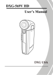
User’s Manual
OPM-4260 | OPM-4260R
• 2012.04.02
Thank you for purchasing our MPDP.
Please read through this user's manual for safety before installing this product.
This product is manufactured for Multi Plasma display model only.
Features of MPDP
Infinitely Expandable
▶E
njoy a wide flat screen with high brightness and high quality.
▶Easy to install and move due to its thin design
▶Enjoy your favorite programs with various split-screen features simultaneously presenting
several programs.
Class A digital device
Notice to users
It is a device designed for business purpose with a safety certificate for electromagnetic interference, which
user should be mindful of.
Thank you for purchasing our MPDP monitor.
This manual describes how to use the product and notes in use.
Please read the manual carefully before using it.
After reading this manual, please retain for future reference.
If you have any questions or a problem occurs, please contact either the company you purchased this
product from or an authorized service center.
※Displaying static picture for an extended period of time may cause an burn-in effect.
Burn-in effect and faults in brightness and picture elements are excluded from the warranty objects.
Warning If you fail to comply with the regulations for safety and proper use,
fire or injury may be caused.
" Important Safety Instructions"
1) Read these instructions.
2) Keep these instructions.
3) Heed all warnings.
4) Follow all instructions.
5) Do not use this apparatus near water.
6) Clean only with dry cloth.
Warning
7) Do not block any ventilation openings. Install in accordance with the manufacturer’s instructions.
To prevent electric shock, Do not remove cover.
No user serviceable part inside
Refer servicing to qualified service personal.
8) Do not install near any heat sources such as radiators, heat registers, stoves, or other apparatus
(including amplifiers) that produce heat.
9) Do not defeat the safety purpose of the polarized or grounding-type plug. A polarized plug has
two blades with one wider than the other. A grounding type plug has two blades and a third
grounding prong. The wide blade or the third prong are provided for your safety. If the provided
plug does not fit into your outlet, consult an electrician for replacement of the obsolete outlet.
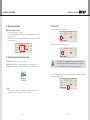
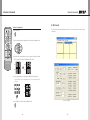
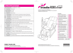
Supplied Accessories
User's Manual
Multi-Screen Control
System(MSCS)
Guide Pin (4pcs)
Ferrite Core (1pc)
Handle (2 pcs)
10) Protect the power cord from being walked on or pinched particularly at plugs, convenience
receptacles, and the point where they exit from the apparatus.
11) Only use attachments/accessories specified by the manufacturer.
DVI-D Cable
Power Cable
RS-232C Cable
12) Use only with the cart, stand, tripod, bracket, or table specified by the
manufacturer, or sold with the apparatus. When a cart is used, use
caution when moving the cart/apparatus combination to avoid injury
from tip-over.
Bolt (4 pcs)
13) Unplug this apparatus during lightning storms or when unused for long periods of time.
14) Refer all servicing to qualified service personnel. Servicing is required when the apparatus has
been damaged in any way, such as power-supply cord or plug is damaged, liquid has been
spilled or objects have fallen into the apparatus, the apparatus has been exposed to rain or
moisture, does not operate normally, or has been dropped.
The symbol in figure 21 shall be shown adjacent to the text of item 12 above.
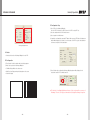
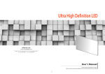
Optional Accessories
MAIN FRAME
(refer to page 16~17)
DVI Converter
(ODC-10000)
New MFC SET
ON
1
OFF
2
3
ID SETTING
4
5
6
7
8
9
SET
BROADCAST
ON
OFF
DVI 1
DVI 2
0
A
B
INFO
DVI
DVI CONVERTER INPUT
VIDEO
PC
DTV
S-VIDEO
HDSDI
DVIC1
DVIC2
OUTPUT
HDMI
INFO
AUTO
FUNCTION
MPDP
PDP
REMOTE CONTROL
※※The ferrite core is used to shield the power cable from interference.
※※When connecting a cable, open the ferrite core and clip it around the cable near the plug.
-1-
Infinitely Expandable
OPM-4260 | OPM-4260R
Contents
CAUTION
RISK OF ELECTRIC SHOCK
DO NOT OPEN
CAUTION : TO REDUCE THE RISK OF ELECTRIC SHOCK,
DO NOT REMOVE COVER (OR BACK).
NO USER-SERVICEABLE PARTS INSIDE.
REFER SERVICING TO QUALIFIED SERVICE PERSONNEL.
This symbol is intended to alert the user to the presence of uninsulated "dangerous
voltage" within the product's enclosure that may be of sufficient magnitude to
constitute a risk of electric shock to persons.
This symbol is intended to alert the user to the presence of important operating and
maintenance(servicing) instructions in the literature accompanying the appliance.
NOTICE
1. To disconnect the apparatus from the mains, the plug must be pulled out from the mains socket,
therefore the mains plug shall be readily operable
2. WARNING - To reduce the risk of fire or electric shock, do not expose this appliance to rain or
moisture.
3. Apparatus shall not be exposed to dripping or splashing and no objects filled with liquids, such
as vases, shall be placed on the apparatus.
4. Use only a properly grounded plug and receptacle
5. "Warning" CAUTION – These servicing instructions are for use by qualified service personnel only.
To reduce the risk of electric shock, do not perform any servicing other than that contained in the
operating instructions unless you are qualified to do so.
※Cautions for consisting MPDP System ...............................................................................................4
※Clearance for Ventilation...............................................................................................................................6
※Do not cover the vent hole for the fan...................................................................................................7
※Cleaning and Maintenance..........................................................................................................................7
※Please keep following instruction for panel protection without exception.......................8
※Handle with Caution........................................................................................................................................9
1. Safety Precautions........................................................................................................................................12
2. How to Install....................................................................................................................................................14
3. Guidance for Users.......................................................................................................................................18
4. How to Connect Cables.............................................................................................................................20
4.1. Connection of Single MPDP...............................................................................................................................20
4.2. Connection of Multiple MPDP............................................................................................................................22
4.3. Connection of Control Cable - In case of using MSCS........................................................................................24
4.4. C
onnection of Control Cable - In case of using the other control program besides MSCS..................................26
4.5. Connection of DVI cable.....................................................................................................................................28
4.6. Connection of optional accessory......................................................................................................................29
4.7. ID setting of X x Y MPDP....................................................................................................................................30
5. Setting and operation of MSCS software.........................................................................................31
5.1. MSCS Installation...............................................................................................................................................31
5.2. Start MSCS........................................................................................................................................................32
5.3. Setting of COM Port...........................................................................................................................................33
5.4. Setting of LAN Port (In case of connecting to a LAN Hub)..................................................................................34
5.5. Setting of LAN Port (In case of connecting directly to user's computer).............................................................36
5.6. "New design/Last design" setting.......................................................................................................................39
5.7. Multi-screen configuration..................................................................................................................................40
5.8. Selecting the command transmission method....................................................................................................40
5.9. Power On/Off.....................................................................................................................................................41
5.10. Changing the input source ..............................................................................................................................44
5.11. Slide Control....................................................................................................................................................47
5.12. Picture Control.................................................................................................................................................50
5.13. Timer Control...................................................................................................................................................51
5.14. Tracking Control ..............................................................................................................................................52
5.15. ORION Homepage log on and Version Information...........................................................................................53
6. Control Method of optional accessory...............................................................................................54
6.1. New MFC .........................................................................................................................................................54
6.2. DVI Converter ..................................................................................................................................................57
7. MSCS Protocol................................................................................................................................................65
※Attachment : ASCII to HEX Conversion Table.........................................................................................................81
8. Other tips............................................................................................................................................................82
8.1. Before calling for service....................................................................................................................................82
8.2. About Plasma display panel...............................................................................................................................83
9. Applicable DVI signals.................................................................................................................................84
10. Specification...................................................................................................................................................85
11. Option Specification..................................................................................................................................87
11.1. DVI Converter...................................................................................................................................................87
11.2. New MFC.........................................................................................................................................................88
-2-
-3-
Infinitely Expandable
OPM-4260 | OPM-4260R
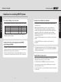
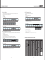
WARNING
The number of Daisy chain connection
Environmental condition for installation
- The image quality may vary depend on the quality of signal and cable condition.
- Since MPDP panel is very sensitive for physical impact, installation requires
considerable caution.
INPUT SOURCE
Resolution
Connection
Remark
DVI
1600 x 1200 x 60Hz
6 sets
HDCP Available
PC
1600 x 1200 x 60Hz
3 sets
VIDEO
NTSC, PAL, SECAM
6 sets
RS-232C
30 sets
ORION Cable Only
- If you need to use more MPDP sets than indicated in the table, using a DVI
distributor is highly recommended.
- Minimum clearance(20cm) must be secured for smooth ventilation. (See
P16~17)Installation must avoid air tight or near air tight places. Improper
ventilation causes malfunction and shortens product lifetime by rapid internal
temperature rise. If MPDP has to be installed at the improper ventilation,
additional ventilation openings or fans must be provided to keep the internal
temperature between 0 ~ 35˚C.
- For ground of MPDP and application devices, it should be connected as frame
ground.
Caution for the other control program besides MPDP
Control Program (MSCS)
- If you want to use automatic power on/off function that make MPDP turned on/
off by connecting main power, allow at least 20 seconds of Stand-by time before
MPDP is turned on, when you make control program.
- If RS-232C communication signal or other image signal is applied to 9 or more
sets simultaneously, communicational error may occur. (Power on & Broadcast)
- Considering MPDP Max power consumption, check the main electric
specification.
※ If the internal temperature reaches to 90˚C, "High Temperature" signal will be
displayed at the lower left corner on the screen for 1minute and the MPDPset
will be turned off automatically.
Consideration for easier service
- When you design the exterior design for MPDP system, consider easier
disassembly for possible service occasion in the future.
- The sliding Universal Unit of ORION is recommended for easier service.
- If service people can step into the backside of MPDP system, it can greatly
reduce time and effort for service.
- In case of higher locations, consider the installation location and exterior design
for easier service.
-4-
-5-
WARNING
※Cautions for consisting MPDP System
Infinitely Expandable
※C
learance for Ventilation
WARNING
-W
hen you install MPDP, make sure there is at least 20cm clearance for
effective ventilation and do not seal off MPDP sets.
If MPDP sets are installed at the locations of bad ventilation, the inner
temperature can be raised rapidly and it can cause frequent malfunctions
and rapid reduction of the product life.
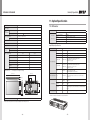
※D
o not cover the vent hole for the fan
-Carefully install MPDP not to cover the fan air holes with any structural
object.
If the holes are covered with anything, the inner temperature can be
raised rapidly and it can cause malfunctions.
Installation structure
FAN
ID SELECT
VIDEO
IN
STB
OUT
PWR ON FAN
PC
CAUTION
RISK OF ELECTRIC SHOCK
DO NOT OPEN
To prevent electric shock,
Do not remove cover.
No user serviceable part inside Refer
servicing to qualified service personal.
IN
OUT
DVI-D
UP
DOWN
FCC Verified : Class "A"
This device complies with the Part 15 of the FCC Rules.
Operation is subject to the following two conditions :
1) This device may not cause harmful interference, and
2) This device must accept any interference received,
including interference that may cause undesired operation.
IN
MPDP
• Model Name : OPM-4260
• Voltage : AC~100 - 240V
• Current : Max. 4A
• Frequency : 50/60Hz
• Serial No :
IN
AUDIO/VIDEO
APPARATUS
E329824
42SS
OUT
RS-232C
LAN
OUT
SVC
PDP CO., LTD.
Made in Korea
※Cleaning and Maintenance
-Regularly clean off the vent holes in the back of MPDP sets.
If the vent holes and the fan air holes are clogged with dust, it prevents
the air flow inside of MPDP sets.
It can cause rapid increase of the inner temperature and may cause
malfunctions.
Clean off the vent holes and the fan air holes with a vacuum cleaner
regularly.
Vacuum Cleaner
ID SELE
CT
VIDEO
• 감전사
고
덮개는 예방을
위하여
• 내부에 열지마세요.
,
PC
는 소비자
있는
부품이 가 수리할
고객
수
A/S팀 없으므로,
으로
연락하
십시오
.
MP
DP
•제
품 명
•모
칭:
PDP
델
• 정격전압
Monito
명:
전류 OPM-4260 r
: AC
•인
100-2
증
40V~,
• 제 자 상 호 4A, 50/60H
조
:오리온
z
• 구입 업 체 명
:오리온피디피(
주)
• 제 및 A/S
조 년,월 : 054) 피디피(
460-5 주)
:
887
DVI-D
RS-23
2C
MadePDP
in Korea
※ Ventilation space in front of MPDP must be furnished for heat dispersion.
If the front space of MPDP has to be sealed, there must be consideration
for the heat dispersion in the rear side of MPDP.
-6-
-7-
LAN
SVC
WARNING
OPM-4260 | OPM-4260R
WARNING
Warning
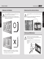
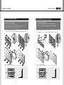
※Please keep following
instruction for panel
protection without exception.
- This product can be damaged even with minor
impact for its nature.
Please keep following instruction to carry or store
the products.
※Handle with Caution.
Warning
PANEL
PANEL
-Shock/Impact on the set's sides will result in internal
circuit damages.
-The edge/bottom of the panel are fragile.
Use shock-absorbing pads or rugs for laying down
the product.
PANEL
PANEL
CUSHION
PANEL
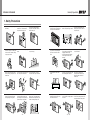
••If you need to stand PDP, you
must use handles on the back
and lean over the PDP to avoid
panel touches ground or floor.
••If you need to lay down PDP as ••If you need to lay down PDP
face down position, please use
as face up position, please be
shock-absorbing pads under the
cautious for falling objects on the
PDP.
surface of the PDP.
-8-
••Please do not stand PDP alone.
It may fall or slip off and Panel
can be broken or damaged.
••Please do not lean over the PDP. ••Please do not lean over the PDP
It may damage the bottom part
toward the edge part. It may
of the PDP.
damage the edge part of the PDP.
-9-
WARNING
Infinitely Expandable
OPM-4260 | OPM-4260R
Infinitely Expandable
OPM-4260 | OPM-4260R
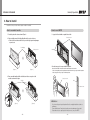
How to carry MPDP
WARNING
Unlike consumer PDP product, the panel of MPDP is exposed without
any protective chassis.
It needs extra caution to carry or install to prevent any impact.
MASTER FRAME
Please see page 14 for unpack and handle assembly.
It always needs two persons to carry or install MPDP.
When you carry MPDP with up straight manner, please hold handles on the
back and bottom part of the panel together.
Please be careful not to touch the bottom part of the panel when you put
down the panel.
PANEL
Please do not touch the panel with your hand.
• OPM-4260
• OPM-4260R
It has to be handled with
care, because the panel glass
substrate is exposed without
side cover.
- 10 -
When you carry MPDP with flatbed manner, please hold handles on the
back and lower part of the back.
Please be careful not to touch the bottom part of the panel when you put
down the panel.
Although Panel is protected
with a Side cover, it is still
sensitive to the impact or
shock from outside.
- 11 -
WARNING
Open Structure
Infinitely Expandable
OPM-4260 | OPM-4260R
1. Safety Precautions
• If it operates abnormally, stop using it
immediately.
• Do not place any liquid-containing
container on it. If the inside is wet, it
may cause electric shock or fire.
• Do not put any foreign material into
the product. It may cause a failure or
shorten the life span.
• Do not pull out or hang down the
connection cable. It may damage the
cord to cause fire or electric shock.
• Do not lean against the product or keep
it leaned. It may cause injury or failure.
• Do not put it at any place with much
humidity, dust, oil, smoke or steam. It
may cause failure.
• Pull out the power plug by holding the
plug. Otherwise, it may damage the
power cord to cause fire or electric
shock.
• If you do not want to use the product
for a long time, keep the power plug
unplugged to save electricity.
• The socket-outlet should be installed
near the equipment and be easily
accessible.
• Do not put any heavy object on it.
It may cause failure.
• Install the product on safe and flat
surface.
• Do not ride or step on the product It may • When moving it, disconnect the
cause breakage when fallen down.
connecting cable. Otherwise, it may
damage the cable to cause fire or
electric shock.
MP
DP
• Please refer to a specialized
• Do not touch the device when lightning
construction company for installing stand strikes.
or wall mount unit. Otherwise, damage
or injury may be caused.
• Do not install in an unstable location
It may cause injury.
• Avoid any action to damage the power
cord or power plug. It may cause fire or
electric shock.
• Do not pull out the power plug with a wet • Do not exceed ratings of AC outlet
hand. It may cause electric shock.
or extension cords. It may cause failure.
• Do not alter (or disassemble) the
product. It may cause electric shock
since high voltage is flowing inside.
• Do not install the product where it may
be exposed to direct sunlight or near
any heating device. It may shorten the
product's life span or cause failure.
- 12 -
• Make sure the product is not covered
with any object. If the ventilation hole is
blocked, the inside temperature may rise
to cause overheating resulting in fire.
• Do not put candles on the product. If the
liquid flows inside the product. It may
cause electric shock or fire.
• Do not touch product’s front surface with • Do not poke the front screen with sharp
hand. Otherwise, the image quality can material. It may damage the screen and
be lowered.
may cause malfunction of the product.
- 13 -
Infinitely Expandable
OPM-4260 | OPM-4260R
2. How to Install
••Install this set only at a location where adequate ventilation is available.
How to assemble handles
How to move MPDP
1. 2 people hold each handle on product's back side.
1. Product is packed in a box as shown in Figure 1.
Panel protection
2. Please carefully remove the Packing Bag with a knife or a pair of scissors.
※ Please check front and rear side before you cut the bag to prevent any damages
on panel or set.
Packing Bag
Panel protection
Handles
MPD
P
MP
DP
2. It needs two people to carry or install this product.
[Figure 1]
[Figure 2]
Please hold the handles in the back and the front bottom part at the same time.
- Please do not grab the panel, but grab bottom of master frame when you carry or install the products.
- Please use gloves when you carry or install the products.
3. P
lease assemble handles with the bolts that are in the accessory box to the
rear side as shown in the figure.
Panel protection
Handles
Panel
Master frame
MP
MP
DP
DP
MPDP
[Figure 3]
[Figure 4]
- 14 -
※※Attention :
-Do not remove the panel protection pad until a set is completely installed on a stand or a
wall hanger.
Please carefully remove Panel protection pad to prevent any damages on the product .
-Please make sure to use panel protection when you move, carry or rent MPDP.
- 15 -
Infinitely Expandable
OPM-4260 | OPM-4260R
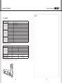
MAIN FRAME Stand Unit (Option)
MAIN FRAME Wall Mounting Unit (Option)
••Please do not install our product at following locations to protect the product
and prevent possible malfunction.
- Places of vibration or shock: PDP set may fall and damaged
-N
ext or near to Sprinkler sensors: The sensors may detect heat from a set and sprinkler can be activated.
- Around high voltage power lines: Noise from the power line may affect screen images
- Around heating apparatus: PDP set may be overheated and damaged.
••The set can be installed as shown below.
(For further information, refer to the optional 'MAIN FRAME Installation and Setup Guide'.)
••Please check the stability of wall.
If the wall is not strong enough, reinforce the wall before installation.
••Please connect all the cables to proper ports in a set before installation.
••The set can be installed on the wall as shown below.
(For further information, refer to the optional 'MAIN FRAME Installation and Setup Guide'.)
MAIN
FRAME
MAIN
Hanger
FRAME
PDP
PDP
WALL
BRACKET
Hanger Bolt
Hanger Bolt
Guide Pin
Guide Pin
Install on a MAIN FRAME Stand
Please secure minimum clearance as shown in the picture for adequate ventilation and technical service.
Mount on the MAIN FRAME wall
Please secure minimum clearance as shown in the picture for adequate ventilation and technical service.
20cm
20cm
20cm
20cm
20cm
20cm
20cm
- 16 -
- 17 -
Hanger
Infinitely Expandable
OPM-4260 | OPM-4260R
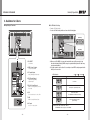
3. Guidance for Users
nnInput/Output Terminals
nnSet ID Switch Setting
••Example of ID Switch setting
- You can set ID with 3 rotary switches as shown in the following figure.
[PDP ID 01]
DOWN
ID SELECT
UP
IN
MPDP
OUT
PWR ON FAN
To prevent electric shock,
Do not remove cover.
No user serviceable part inside Refer
servicing to qualified service personal.
SVC
PDP CO., LTD.
Made in Korea
IN
FCC Verified : Class "A"
OUT
DVI-D
This device complies with the Part 15 of the FCC Rules.
Operation is subject to the following two conditions :
1) This device may not cause harmful interference, and
2) This device must accept any interference received,
including interference that may cause undesired operation.
UP
LAN
OUT
DOWN
AUDIO/VIDEO
APPARATUS
E329824
42SS
78
PC
RISK OF ELECTRIC SHOCK
DO NOT OPEN
RS-232C
IN
100 digit 10 digit single digit
VIDEO
IN
STB
OUT
CAUTION
• Model Name : OPM-4260
• Voltage : AC~100 - 240V
• Current : Max. 4A
• Frequency : 50/60Hz
• Serial No :
78
78
456
OUT
DVI-D
456
IN
901
456
PC
CAUTION
RISK OF ELECTRIC SHOCK
DO NOT OPEN
To prevent electric shock,
Do not remove cover.
No user serviceable part inside Refer
servicing to qualified service personal.
FCC Verified : Class "A"
This device complies with the Part 15 of the FCC Rules.
Operation is subject to the following two conditions :
1) This device may not cause harmful interference, and
2) This device must accept any interference received,
including interference that may cause undesired operation.
901
23
OUT
PWR ON FAN
23
VIDEO
IN
23
ID SELECT
STB
901
IN
MPDP
• Model Name : OPM-4260
• Voltage : AC~100 - 240V
• Current : Max. 4A
• Frequency : 50/60Hz
• Serial No :
AUDIO/VIDEO
APPARATUS
E329824
42SS
[PDP ID 15]
OUT
RS-232C
IN
LAN
OUT
78
Made in Korea
23
901
SVC
PDP CO., LTD.
456
100 digit 10 digit single digit
AC 100V ~ 240V, 50/60Hz
- 18 -
78
456
8. AC Input
STB
PWR ON
78
78
901
78
78
78
901
Insert power cord(Stand-By state)
FAN
Power On By MSCS.
The PWR ON LED blinks continually.
FAN
901
Power Off by MSCS Program.
(System ready).
23
❽
901
23
MPDP Control by Ethernet, RJ45
23
7. LAN
PWR ON
901
78
STB
901
78
78
901
78
For the exclusive use of service, RJ11
PWR ON
No Power.
FAN
23
6. SVC
901
23
❼
STB
78
❻
901
456
SVC
MPDP Control, Upgrade by Com Port,
D-sub 9pin
BLINKING
Description
23
LAN
OUT
5. RS-232C Input/Output
23
PDP CO., LTD.
Made in Korea
❺
23
RS-232C
IN
AUDIO/VIDEO
APPARATUS
E329824
42SS
OUT
PWR ON
23
• Model Name : OPM-4260
• Voltage : AC~100 - 240V
• Current : Max. 4A
• Frequency : 50/60Hz
• Serial No :
Digital RGB Signal(TMDS),
single link 24pin
STB
IN
MPDP
❹
OFF
901
23
DVI-D
This device complies with the Part 15 of the FCC Rules.
Operation is subject to the following two conditions :
1) This device may not cause harmful interference, and
2) This device must accept any interference received,
including interference that may cause undesired operation.
901
23
FCC Verified : Class "A"
OUT
901
23
IN
LED Indication
78
4. DVI-D Input/Output
ON
456
PC
CAUTION
RISK OF ELECTRIC SHOCK
DO NOT OPEN
To prevent electric shock,
Do not remove cover.
No user serviceable part inside Refer
servicing to qualified service personal.
••LED Indication
456
Analog RGB Signal, D-Sub 15pin
PWR ON FAN
456
3. PC Input/Output
456
STB
❸
OUT
456
VIDEO
IN
Composite Signal, BNC
456
ID SELECT
2. VIDEO Input / Output
456
❷
456
Set ID Switch
※※When you set ID of MPDP set, power cable must be disconnected. If power cable is not
disconnected during ID setting, MPDP set may be operated with the previous ID and it may
cause abnormal behavior.
※※For stable operation, wait for at least 10 seconds prior to use MPDP control program after the
first AC power connection.
456
1. ID SELECT
456
❶
FAN
FAN : Normal - LED Off, Abnormal - LED On
IF FAN LED is turned on, please check FANs.
- 19 -
Infinitely Expandable
OPM-4260 | OPM-4260R
4. How to Connect Cables
••Do not connect/disconnect cables while MPDP or other external equipments are turned on.
••First turn off the power all the attached equipment and make connections.
4.1. Connection of Single MPDP
••MPDP and PC should be connected; a Com Port in a PC and RS-232C IN port in a MPDP is
connected with supplied RS-232C cable.
VIDEO
IN
DOWN
OUT
PWR ON FAN
PC
IN
FCC Verified : Class "A"
OUT
DVI-D
This device complies with the Part 15 of the FCC Rules.
Operation is subject to the following two conditions :
1) This device may not cause harmful interference, and
2) This device must accept any interference received,
including interference that may cause undesired operation.
UP
IN
MPDP
• Model Name : OPM-4260
• Voltage : AC~100 - 240V
• Current : Max. 4A
• Frequency : 50/60Hz
• Serial No :
AUDIO/VIDEO
APPARATUS
E329824
42SS
OUT
RS-232C
IN
LAN
OUT
SVC
PDP CO., LTD.
Made in Korea
OUT
PWR ON FAN
IN
PC Connection
(Maximum 5m)
OUT
DVI-D
DVI connection
(Maximum 5m)
IN
OUT
RS-232C
IN
RS-232C (Maximum
15m)
OUT
LAN
SVC
PC (MSCS) to control MPDP
- 20 -
78
78
78
456
IN
STB
VCR
PC
456
VIDEO
PC
you need longer
connection, please use DVI
boosters or DVI fiber-optic
cable.
23
••ID switch must be set as ID 1
for one set use.
ID SELECT
※If
901
[MPDP ID 1]
••If you do not have Com Port, you need to use an USB converter for RS-232C. Depending on
manufacturers or models, converters may cause malfunction.
Video connection
(Maximum 5m)
901
23
••ID setting on the backside of MPDP must be identical with the ID setting in MSCS to control
MPDP with a PC.
23
901
456
••MPDP On/Off or Screen adjustment can be controlled by MSCS (Multi-Screen Control
System).
ID SELECT
STB
CAUTION
RISK OF ELECTRIC SHOCK
DO NOT OPEN
To prevent electric shock,
Do not remove cover.
No user serviceable part inside Refer
servicing to qualified service personal.
- 21 -
Infinitely Expandable
OPM-4260 | OPM-4260R
4.2. Connection of Multiple MPDP
••Recommended maximum set connection for Multi setting is shown in table below.
If you need to connect more than described in the table, you have to use distributors.
••Image quality can be affected by cable or signal quality.
INPUT SOURCE
Resolution
Connection
Remark
DVI
1600 x 1200 x 60Hz
6 sets
HDCP Available
PC
1600 x 1200 x 60Hz
3 sets
VIDEO
NTSC, PAL, SECAM
6 sets
RS-232C
30 sets
ID SELECT
VIDEO
VIDEO
IN
STB
ORION Cable Only
ID SELECT
OUT
PWR ON FAN
IN
STB
VCR
VIDEO
IN
IN
PC
IN
IN
PC
OUT
IN
DVI-D
OUT
IN
OUT
IN
- 22 -
OUT
RS-232C
RS-232C
RS-232C
RS-232C
RS-232C
IN
IN
IN
IN
IN
LAN
MPDP 1
OUT
DVI-D
OUT
SVC
LAN
OUT
SVC
LAN
OUT
SVC
LAN
OUT
SVC
LAN
RS-232C
PC (MSCS) to control
MPDP
OUT
PWR ON FAN
PC
OUT
IN
VIDEO
IN
STB
DVI-D
OUT
ID SELECT
OUT
PWR ON FAN
PC
OUT
IN
VIDEO
IN
STB
DVI-D
OUT
ID SELECT
OUT
PWR ON FAN
PC
OUT
IN
IN
STB
DVI-D
DVI
VIDEO
OUT
PWR ON FAN
PC
PC
ID SELECT
MPDP 2
MPDP 3
MPDP 4
MPDP 5
- 23 -
OUT
SVC
Infinitely Expandable
OPM-4260 | OPM-4260R
4.3. Connection of Control Cable - In case of using MSCS
••Control signal transmission can be connected by 2 different methods.
(RS-232C or Ethernet)
•• RS-232C and Ethernet connection cannot be used simultaneously.
4.3.2. Connection of Ethernet Cable
4.3.1. Connection of RS-232C Cable
••In case of Ethernet connection, the control PC should be connected to one of MPDP sets with
Ethernet cable. For the connection between the MPDP sets, they should be connected with
RS-232C cables.
••Maximum use of RS-232C with Daisy Chain connection is 30 sets or less, if you need
additional connection, use RS-232C distributor.
ID 1
ID 2
RS-232C
RS-232C
ID 3
RS-232C
ID 1
RS-232C
ID 2
LAN
IN
ID 4
OUT
IN
ID 5
RS-232C
OUT
RS-232C
IN
ID 6
OUT
RS-232C
OUT
RS-232C
ID 5
OUT
IN
ID 7
OUT
ID 8
IN
OUT
RS-232C
OUT
IN
OUT
IN
LAN Cable
(Direct Cable)
RS-232C
IN
RS-232C
LAN
IN
OUT
RS-232C
IN
OUT
IN
RS-232C
RS-232C control PC
- 24 -
OUT
LAN
LAN Cable
(Cross Cable)
HUB or Router
(Wireless & Cable)
OUT
ID 9
RS-232C
OUT
ID 6
OUT
ID 8
RS-232C
IN
LAN
IN
LAN
IN
RS-232C
OUT
ID 7
ID 9
RS-232C
OUT
LAN
IN
RS-232C
LAN
IN
LAN
IN
ID 3
LAN
IN
ID 4
RS-232C
LAN Cable
(Direct Cable)
- 25 -
Ethernet control PC
OUT
Infinitely Expandable
OPM-4260 | OPM-4260R
4.4. Connection of Control Cable - In case of using the other control program
besides MSCS
※ If you use the other screen control program besides MSCS, the signal cable
must be connected via MFC (Multi- Function Controller) of ORION.
••Control signal transmission can be connected by 2 different methods. (RS-232C or Ethernet)
•• RS-232C and Ethernet connection cannot be used simultaneously.
4.4.2. Connection of Ethernet Cable
••If you want to control MPDP sets with Ethernet, PC and MFC can be connected with Ethernet
cable and between MFC and the first MPDP set and between the other MPDP sets should be
connected with RS-232C cable.
4.4.1. Connection of RS-232C Cable
••The RS-232C signal cable must be connected via MFC.
••Maximum use of RS-232C with Daisy Chain connection is 30 sets or less, if you need additional
connection, use RS-232C distributor.
ID 1
RS-232C
LAN
RS-232C
IN
ID 2
RS-232C
OUT
IN
ID 3
OUT
OUT
ID 5
RS-232C
IN
ID 6
OUT
ID 4
RS-232C
OUT
IN
OUT
ID 5
IN
ID 6
RS-232C
LAN
IN
OUT
IN
IN
ID 8
RS-232C
RS-232C
LAN
OUT
RS-232C
LAN
IN
OUT
IN
RS-232C
RS-232C
IN
OUT
IN
OUT
IN
OUT
LAN Cable
(Cross Cable)
New MFC
HUB or Router
(Wireless & Cable)
Ethernet control PC
RS-232C
New MFC
RS-232C control PC
- 26 -
OUT
ID 9
RS-232C
OUT
ID 9
RS-232C
OUT
RS-232C
IN
ID 8
RS-232C
OUT
LAN
ID 7
OUT
LAN
ID 7
IN
RS-232C
RS-232C
IN
RS-232C
ID 3
LAN
IN
LAN
ID 4
RS-232C
LAN
IN
ID 1
ID 2
LAN Cable
(Direct Cable)
- 27 -
OUT
Infinitely Expandable
OPM-4260 | OPM-4260R
4.5. Connection of DVI cable
RS-232C
DVI-D
4.6. Connection of optional accessory
DVI-D
RS-232C
DVI-D
RS-232C
RS-232C
ID 1
IN
ID 2
OUT
IN
IN
ID 3
OUT
OUT
IN
IN
OUT
IN
OUT
IN
DVI-D
RS-232C
OUT
IN
OUT
IN
DVI-D
DVI-D
RS-232C
IN
ID 5
OUT
IN
IN
IN
IN
DVI-D
DVI-D
OUT
IN
OUT
IN
DVI-D
RS-232C
OUT
IN
OUT
IN
IN
OUT
IN
OUT
ID 8
IN
OUT
IN
OUT
IN
DVI-D
RS-232C
OUT
IN
OUT
IN
DVI-D
DVI-D
OUT
OUT
IN
OUT
ID 6
OUT
IN
IN
OUT
IN
OUT
IN
DVI-D
RS-232C
RS-232C
OUT
IN
OUT
IN
ID 7
IN
OUT
ID 9
DVI Signal Distributor
New MFC
DVI Converter
DVI
DVI-D
OUT
OUT
ID 8
DVI Signal Distributor
(UXGA : UP TO 165MHz)
RS-232C control PC
OUT
DVI-D
RS-232C
ID 9
IN
ID 5
RS-232C
ID 7
OUT
OUT
ID 3
RS-232C
ID 4
RS-232C
DVI-D
DVI-D
RS-232C
ID 6
OUT
OUT
IN
IN
ID 2
RS-232C
ID 4
RS-232C
OUT
OUT
ID 1
RS-232C
DVI-D
DVI
HDMI
HD-SDI
PC
Component
S-Video
CVBS
RS-232C
RS-485 USB
Ethernet
※※Caution for DVI Distributor
If you want to display HDCP (High-bandwidth Digital Content Protection) applied
contents, you must use the distributor that supports HDCP function.
Video Source
- 28 -
- 29 -
Control System
Infinitely Expandable
OPM-4260 | OPM-4260R
5. Setting and operation of MSCS software
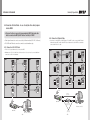
4.7. ID setting of X x Y MPDP
[MPDP ID 01]
901
901
23
456
23
78
100 digit 10 digit single digit
78
••When you look at the MPDP screens in front of MPDP.
456
23
••Identity number (ID) indicates the location of each MPDP.
78
901
456
PDP ID
1
PDP ID
2
PDP ID
3
PDP ID
4
PDP ID
5
PDP ID
6
PDP ID
7
PDP ID
8
PDP ID
9
PDP ID
10
PDP ID
11
PDP ID
12
PDP ID
13
PDP ID
14
PDP ID
15
PDP ID
16
PDP ID
17
PDP ID
18
PDP ID
19
PDP ID
20
PDP ID
21
PDP ID
22
PDP ID
23
PDP ID
24
PDP ID
25
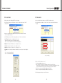
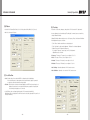
5.1. MSCS Installation
••Insert the Installation CD.
••You can see following installation start screen.
••Select proper version for your product and start installation
••MSCS supports Windows® 2000, Windows® XP and Windows® Vista, Windows® 7™ only
Recommended ID of X x Y screens
78
78
78
78
78
78
78
78
78
78
78
78
78
78
78
78
78
78
78
78
78
78
78
78
78
78
78
78
456
456
78
78
78
456
78
78
78
78
456
456
78
78
78
78
78
456
78
78
456
78
78
78
78
456
78
456
78
78
78
456
78
456
78
456
456
456
78
456
78
456
456
78
456
456
456
78
※※Caution for using MSCS
Caution
1. Data for Picture control, Manual Tracking and so forth can be read by clicking
the right button of your mouse on the desired MPDP set from MSCS.
Please do not use above function together with the other functions.
2. When you off AC power, execute power off by MSCS first and disconnect AC
power to save your configuration.
456
456
456
78
456
456
456
456
78
456
456
78
456
456
456
456
78
456
456
456
456
78
456
456
456
456
456
78
456
456
78
456
456
456
78
456
456
456
78
456
901
23
901
23
901
23
901
23
456
456
78
456
456
456
78
456
456
456
78
456
901
23
901
23
456
78
456
901
ID 25
901
23
456
456
78
456
78
456
456
78
456
456
78
MSCS Installation start screen.
23
901
23
901
23
901
23
456
78
901
23
23
901
ID 20
901
23
456
456
78
901
23
23
901
23
901
23
23
901
23
23
23
- 30 -
901
901
ID 15
901
ID 24
901
901
23
901
23
23
901
23
23
901
23
23
23
901
23
23
901
901
ID 10
901
ID 19
901
23
901
23
23
23
901
901
23
23
901
ID 23
901
901
ID 14
901
23
901
23
23
901
ID 5
901
ID 9
901
23
23
23
901
901
23
23
23
901
ID 18
901
23
901
23
23
23
23
901
901
23
23
901
ID 22
901
ID 4
901
ID 13
901
23
901
23
23
23
23
901
23
23
23
901
ID 17
901
ID 21
901
901
23
23
23
23
901
901
ID 8
901
ID 12
901
ID 16
901
901
23
23
901
ID 11
901
901
ID 7
901
23
23
901
ID 3
901
23
ID 6
901
23
23
901
456
ID 2
901
23
23
901
456
ID 1
- 31 -
456
Infinitely Expandable
OPM-4260 | OPM-4260R
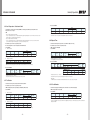
5.2. Start MSCS
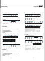
5.3. Setting of COM Port
••MSCS is an application program needed to control MPDP.
••Com Port connects or disconnects the communication between PC and MPDP.
••When you execute MSCS for your product at the installation screen, it will create a new folder
at C:/Program File/MSCS and an icon on your computer screen.
••Connect MPDP to PC Com Port via RS-232C cable.
••By double clicking the MSCS icon, the initial screen image of MSCS will be displayed
as shown in the picture.
••Go to MSCS Menu -> Communication and set Com Port. Click 'Connect' using mouse or
press 'Ctrl+C' using keyboard.
••In order to disconnect communication, click 'Disconnect' using mouse or press 'Ctrl+D' using
keyboard.
When you use USB-to-RS-232C converters, you need to set Com Port again,
because MSCS uses one of Com Port no. 1 to 30.
※Available Com Port on the PC is automatically recognized and displayed.
••Com Port Configuration
Baud Rate
115200bps(Fixed)
Data Bit
8Bits
Parity
None
Stop Bit
1Bit
Flow Control
None
Main Image of MSCS (Multi Screen Control system)
※ To install MSCS, you need the account for the administrator.
Caution
※C
heck whether Windows Firewall or anti-virus program prohibits the
access of MSCS to the IP address of the display.
- 32 -
- 33 -
Infinitely Expandable
OPM-4260 | OPM-4260R
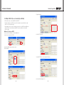
5) Type in IP Address.
5.4. Setting of LAN Port (In case of connecting to a LAN Hub)
••This function is used to control the MPDP via LAN PORT.
* During the setting process, MPDP and control PC should be connected via RS-232C cable
only. Do not connect ethernet cable.
* After setting process, the control PC should be connected to one of MPDP sets with Ethernet
cable only. For the connection between the MPDP sets, they should be connected with
RS-232C cables.
nnNetwork IP setting for MPDP
1) Execute the LAN Configurator V1.0 from installation CD.
6) Click "SET TCP/IP Info".
2) Select Com Port and select "OPEN".
3) Select ID of MPDP which you want to control.
4) Turn off MPDP.
7) Click "GET TCP/IP Info." and Confirm the IP Address.
8) Close the LAN Configurator V1.0
- 34 -
- 35 -
Infinitely Expandable
OPM-4260 | OPM-4260R
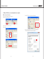
5.5. Setting of LAN Port (In case of connecting directly to user's computer)
nnCheck the network informations
1) Execute the LAN Configurator V1.0 from installation CD.
5) Click "GET TCP/IP Info." and check the network informations.
2) Select Com Port and select "OPEN".
3) Select ID of MPDP which you want to control.
4) Turn off MPDP.
6) Input the network information of the user’s PC to be identical with MPDP set.
However, the final digit of the IP address must be different.
- 36 -
- 37 -
Infinitely Expandable
OPM-4260 | OPM-4260R
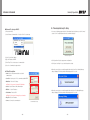
5.6. "New design/Last design" setting
nnNetwork IP setting for MSCS
1) Execute the MSCS.
••You can see following pop-up window for "New design/Last design" when you click "Connect"
or press "Ctrl+C" using keyboard after select communication type.
2) Select "Menu->Communication -> Setup" or"Ctrl+U" to start setup.
New/Last Design Set
3) Select "Socket" radio button.
4) Type in IP Address of MPDP.
••Click "Open New Design" to prepare new configuration.
5) Click "Ping Test" to check status of communication.
••Click "Open Last Design" to go to last design before closing.
6) Close the Commnication setup window
••When the connection is successfully completed after setting Com Port, following Message
dialog is displayed. The dialog window will be disappeared in 1 second.
▶ Menu Description
••Serial : Set the serial communication as a default
communication.
••Com Port : Set the port of a PC to communicate with MPDP.
••Baud Rate : Fixed at 115200bps.
※※Caution: Users cannot change the Baud rate.
••Socket : Set the Ethernet LAN communication.
••Edit Box : Set the IP address.
••When the connection is successfully completed after setting Lan Port, following Message
dialog is displayed. The dialog window will be disappeared in 1 second.
••Port Number : Fixed as 9761.
※※Caution: Users cannot change the port number.
••Ping Test: Test the IP address.
••Connect : Connect the communication.
Communication Setup
- 38 -
- 39 -
Infinitely Expandable
OPM-4260 | OPM-4260R
5.7. Multi-screen configuration
5.9. Power On/Off
nnInput the numbers of X and Y
1) Power On: Press On button in the Power Mode.
−− X is for the number of row and Y is for column.
−− X and Y can be selected within the range from 1 to 15. The maximum MPDP quantity of MSCS
control is 100 sets.
−− MPDP image of selected numbers of X and Y is displayed in the Screen configuration in one second
after setting the number.
2) Power Off: Press Off button in the Power Mode.
Screen Configuration Setting
5.8. Selecting the command transmission method
••ONE PDP : Transmit Protocol Command to one MPDP.
••ALL PDP : Transmit the Protocol command sequentially to all connected MPDP sets.
••Broadcast : Transmit the Protocol command simultaneously to all connected MPDP sets.
Caution
It needs about 10 second standby time before pressing the Power On button if the
power is newly connected. Without the standby time, it may cause malfunction.
In case of malfunction, disconnect the power plug and connect it again.
3) Power off for Afterimage Mitigation: Power off after displaying a pattern to mitigate the afterimage.
Press Afterimage Mitigation button.
※※INFO :
−− Check the resolution of the input source. It is displayed at the upper right corner of the screen.
−− Check the signal. If there is no input signal, "No signal" is displayed.
- 40 -
- 41 -
Infinitely Expandable
OPM-4260 | OPM-4260R
C. Configuration Step
1)Select PDP set for Afterimage Mitigation
Select ALL PDP or Broadcast for all PDP sets and One PDP for single PDP set.
2) Select the duration time in the Time Duration menu.
3) Select a pattern in the Mode menu.
4) Complete the configuration by pressing SET button. When you press SET button, following menu
window will be displayed. If you want to check the status of each PDP set, press the right button
of the mouse and press Check Status button.
Afterimage Mitigation Menu
A. Status
••It indicates the function of Afterimage Mitigation for each PDP.
B. Configuration
1) Time Duration: Decide the duration time for the display pattern.
2) Mode: Select a pattern for Afterimage Mitigation
••Full White: Display White on the entire screen.
••White Bar Scan: Display moving white bar pattern on the screen
••Default: No display
5) Press Off button after configuration, Afterimage Mitigation pattern will be displayed for the
selected time and the PDP set will be turned off.
※ This function is for mitigating Afterimage. However, it does not prevent the occurrence of
Afterimage. Therefore, it is highly recommended not to display fixed image for long time.
- 42 -
- 43 -
Infinitely Expandable
OPM-4260 | OPM-4260R
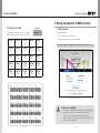
5.10. Changing the input source
••Varieties of screen formations are available with screen configuration.
••Select DVI, PC or Video at the Input Select menu.
5.10.1. If you select DVI and click Play button at the Input Select menu, the
input source will be changed from PC to DVI .
5.10.2. Screen formation
••To make various Input-screen formation, select an input source and click the screen you want
in the Screen configuration with the left button of the mouse.
−− In case you do not select a screen and click Play, the input source for the all screen will be changed.
1) Select PC at the Input Select menu.
−− e.g.) in case PC is selected
2) Click the screen you want in the Screen configuration with the left button of the mouse.
−− Click the screen you want in the Screen configuration with the left button of the mouse.
−− DVI screen will be changed with PC.
Select DVI at the Input Select menu
PC
DVI
DVI
DVI
PC
DVI
DVI
DVI
DVI
※Input source is not displayed on the MSCS screen, but it is indicated by colors.
(DVI : Yellow PC : Green Video : Gray)
- 44 -
- 45 -
Infinitely Expandable
OPM-4260 | OPM-4260R
5.10.3. Screen Formation with one step.
5.11. Slide Control
••You can make various multi-screen formations with simple movement.
••MPDP configuration that users can choose is displayed repeatedly.
••To use Slide Control, go to MSCS Menu -> Control -> Slide Control or press "Ctrl+S" using
Keyboard.
1) Select an input source at Source Select menu.
−− e.g.) In case you want to select PC
2) Click the screen you want in the Screen Configuration with the left button of the mouse and
drag.
−− Click the screen you want in the Screen Configuration with the left button of the mouse and drag to
the screen you want to include.
−− When you stop dragging, selected screens will be changed to PC automatically.
DVI
DVI
DVI
DVI
DVI
PC
DVI
PC
PC
PC
DVI
1) Make a desirable configuration in "Screen Configurations"
DVI
DVI
DVI
DVI
DVI
DVI
DVI
DVI
DVI
DVI
2) Set "Operation Time" in "Slide Control"
DVI
DVI
DVI
DVI
- 46 -
DVI
DVI
−− Click "Add" button to save configuration.
−− The range of "Operation Time" is from 10 seconds to 1 hour.
DVI
DVI
DVI
DVI
DVI
DVI
DVI
DVI
DVI
- 47 -
Infinitely Expandable
OPM-4260 | OPM-4260R
3) Save various screen configurations in the same way.
6) Click "Stop" button to end "Slide Control"
DVI
PC
PC
DVI
PC
PC
DVI
PC
PC
4) Click "Slide Start" to display saved screen configurations.
7) Save or Load the slide configuration
−− Saved screen configurations are displaying for preset time.
PC
PC
DVI
PC
PC
DVI
DVI
DVI
DVI
−− Click "SAVE" button to save user added Slide configuration as "*.ssd" file.
−− Click "LOAD" button to open saved "*.ssd" file.
Caution
When you load "Slide File", previous slide
configuration and new slide configuration must
be identical.
If they are different, the file cannot be loaded.
So, revise the new slide file configuration as
previous configuration or save as new file.
5) Check "Repeat" to display saved configuration repeatedly.
※※To view the saved screen configuration, select the list from "List Box."
※※Saved screen protocol is transmitted to MPDP by double clicking the list.
- 48 -
- 49 -
Infinitely Expandable
OPM-4260 | OPM-4260R
5.12. Picture Control
5.13. Timer Control
••Register values related to display of MPDP can be changed.
••Users can decide the time of turning on or off MPDP set by timer control.
••To use Picture Control, go to MSCS Menu -> Control -> Picture Control or press "Ctrl+P"
using Keyboard.
••To use this function, click Menu -> Control-> Timer Control or use 'Ctrl +M' keys from the
keyboard.
••In order to control display values, input values directly in "Edit Box" and press Enter key.
Or click -/+ button using mouse.
••Click "Exit" button or press "Ctrl+X" using keyboard to close "Picture Control" window.
••Color Temp : Change the color temperature of the screen
-Normal : Initial setting. Proper for normal video image view.
-Studio : Low Color temperature. Proper for broadcasting purpose.
••Brightness : The range of "Brightness" you can adjust is 0 to 100.
••Contrast : The range of "Contrast" you can adjust is 0 to 100.
••Sharpness : The range of "Sharpness" you can adjust is 0 to 28.
••User Data : Users can adjust color impression with white screen and save or load the adjusted
value.
- Save - Save User’s data file (*.pdt)
- Load - Load User’s data file (*.pdt)
Timer Control Dialog
••How to set the time of power on or off.
I. Select Hour and Minutes of turn on or off
II. After setting Power On/Off time, click “Add” button to add it to Power On/Off List Box.
You can save up to 10 settings for Power On/Off. Also, you can delete the saved settings in the List Box
one by one with “Remove” button. If you delete all the settings, click “Remove All” button.
III.Select once for one time use and Daily for daily use, then click 'Start'
IV.Power on or off signal will be transmitted to MPDP at the time of user set.
••Time Dialog must be activated to use Timer function
- 50 -
- 51 -
Infinitely Expandable
OPM-4260 | OPM-4260R
5.14. Tracking Control
5.15. ORION Homepage log on and Version Information
••Alignment adjustment is available when input source is PC.
••In order to move to Orion website, go to "Help" of menu bar ->"OrionDisplay HomePage".
••Go to "Control" in menu bar -> Tracking Control or press
"Ctrl+T" using keyboard to run "Tracking" window.
ORION Homepage Log on
••Press "Tracking Auto" button in order to run auto tracking.
••In case alignment doesn't work through "Tracking Auto"
command, user can tune finely through "Manual".
••Go to "Help" of menu bar -> "About" to check MSCS.
••Manual Tracking enables users to set Frequency, Phase,
LineStart and PixelStart.
••Select panel ID which you want to adjust alignment.
Tracking Manual Window
••Detail adjustment steps are as follows.
1) Tune "Phase" until the vertical lines are clearly adjusted..
2) Tune "LineStart" to adjust vertical alignment. "PixelStart" for horizontal alignment.
3) Adjust "Frequency" if alignment is still wrong.
If you adjust "Frequency", repeat step 1) and 2) to fit alignment.
Adjustable range is as follows
-The range of "Frequency" you can adjust is -50 to 50
-The range of "Phase" you can adjust is 0 to 63
-The range of "Linestart" you can adjust is -23 to 10
Checking MSCS Version
-The range of "Pixelstart" you can adjust is -50 to 40
••Click "EXIT" button or press "Ctrl+X" using keyboard to close "Tracking" window.
※※When "Tracking" windows is on display, users cannot display "Picture Control"
window.
※※Even when "Tracking" window is on display, selecting panel ID is available by clicking
right button of mouse.
- 52 -
- 53 -
Infinitely Expandable
OPM-4260 | OPM-4260R
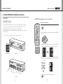
6. Control Method of optional accessory
6.1. New MFC
(2) MPDP Set Configuration (e.g. X:5 sets x Y:6 sets)
(1) New MFC Connection
Horizontal configuration
1) Connect power of New MFC
2) Connect female D-sub of New MFC to the Com port in the computer with RS-232C cable.
ON
3) Connect male D-sub of New MFC to the RS-232C port in MPDP with RS-232C cable.
5) Set the number of the connected MPDP units in advance. The number can be set only by the
Remote controller.
ID SETTING
4) Install the New MFC at the location of good Remote controller reception.
1
2
3
4
5
6
7
8
※※ For the additional information refer to the "New MFC manual"
9
BROADCAST
ON
OFF
DVI 1
DVI 2
0
SET
1. Press SET button .
OFF
A
B
SET
2. Press Left and Right buttons sequentially to enter the horizontal configuration
mode.
INFO
DVI
VIDEO
PC
DTV
S-VIDEO
HDSDI
DVIC1
DVIC2
OUTPUT
HDMI
INFO
AUTO
FUNCTION
MPDP
HOR
PDP
REMOTE CONTROL
VER
MPDP "N x M" Configuration
New MFC Front
INFO
DVI CONVERTER INPUT
3. When the 2 LEDs at lower right corner of each 7-segment of lower line in the
New MFC are turned on, the horizontal configuration mode is started.
HOR
HOR
VER
VER
4. Use the number buttons to set the numbers of MPDP sets in horizontal line.
-e.g. If you want to set 5 for horizontal number, press "0" for ten's place and
"5" for one's place.
1
2
3
4
5
6
7
8
9
AS Connect
Adaoter Jack
(5V 1A)
HOR
VER
0
USB Connect
Ethernet Connect
PC Connect
MPDP Connect
New MFC Rear
- 54 -
5. Pres SET button to finish the horizontal configuration mode.
SET
- 55 -
Infinitely Expandable
OPM-4260 | OPM-4260R
6.2. DVI Converter
Vertical configuration
ON
OFF
ID SETTING
1
2
3
4
5
6
7
8
9
BROADCAST
ON
OFF
DVI 1
DVI 2
0
SET
••To use DVI Converter, go to MSCS Menu -> Device -> DVI Converter or press "Ctrl+V" using
Keyboard.
1. Press SET button.
A
SET
2. Press Up and Down buttons sequentially to enter the vertical configuration mode.
B
INFO
INFO
DVI
DVI CONVERTER INPUT
VIDEO
PC
DTV
S-VIDEO
HDSDI
DVIC1
DVIC2
OUTPUT
HDMI
INFO
AUTO
FUNCTION
MPDP
PDP
REMOTE CONTROL
3. When the 2 LEDs at lower right corner of each 7-segment of lower line in the New
MFC are turned on, the vertical configuration mode is started.
HOR
HOR
VER
VER
4. Use the number buttons to set the numbers of MPDP sets in horizontal line.
-e.g. If you want to set 6 for vertical number, press "0" for ten's place and "6" for
one's place.
1
2
3
4
5
6
7
8
9
HOR
VER
0
5. Pres SET button to finish the vertical configuration mode.
DVI Converter Dialog
SET
- 56 -
- 57 -
Infinitely Expandable
OPM-4260 | OPM-4260R
(1) ID
(4) Output Resolution
••Set the ID of DVI Converter. The ID can be selected from 1 to 9.
••Set the output resolution of DVI Converter.
(2) CMND
••Select the channel of DVI converter to control.
••One of DVI Channel 1(DVIC1), DVI Channel 2(DVIC2), and ALL DVI Channel can be selected.
Resolution
frequency
640 x 480
60Hz / 85Hz
800 x 600
50Hz / 60Hz / 85Hz
853 x 480
50Hz / 60Hz
1024 x 768
60Hz / 85Hz
1280 x 1024
50Hz / 60Hz
1600 x 900
50Hz / 60Hz
1600 x 1200
50Hz / 60Hz
1706 x 960
60Hz
1920 x 1080p
50Hz / 60Hz
••Set : Set the output resolution.
(5) OSD Information
••The DVI Converter input mode and input resolution are displayed on the screen.
(3) Input Mode
••Select the input mode of DVI Converter.
••One of DVI, HDMI, HDSDI, PC, DTV, S-VIDEO, and VIDEO can be selected.
(6) Aspect Ratio
••Set : Select one of 7 Input Modes and press "Set".
••Set or change the screen ratio (Horizontal: Vertical)
••16 : 9 : Set the screen ratio as 16:9 wide screen.
••4 : 3 : Set the screen ratio as 4:3
••LB(Letter Box) : Expand the screen image to remove the black patterns at the top and
bottom portions of the screen.
••LBS(Letter Box Subtitle) : Expand the screen with the subtitle to the top portion. (The bottom
portion remains with black pattern)
- 58 -
- 59 -
Infinitely Expandable
OPM-4260 | OPM-4260R
(7) Key Lock Mode
(9) Picture Control
••Lock the front key of DVI Converter not to turn On or Off.
••Control the Brightness, Contrast, Sharpness, Color, and Tint of the DVI Converter.
••Brightness : The range of "Brightness" you can adjust is 0 to 100.
••Contrast : The range of "Contrast" you can adjust is 0 to 100.
••Sharpness : The range of "Sharpness" you can adjust is 0 to 28.
••Color : The range of "Color" you can adjust is 0 to 100.
(8) Status
••Tint : The range of "Tint" you can adjust is 0 to 90.
••Display the DVI Converter status (Input Source, Input Resolution, Output Resolution, Aspect
Ratio, PIP Mode, Test Pattern, Key Lock, FreeRun/Lock, Firmware Version, MSCS Version
information)
- 60 -
••Firmware Default : Initialize the adjusted values to the default values.
- 61 -
Infinitely Expandable
OPM-4260 | OPM-4260R
(10) Pattern
(12) Tracking
••Select the Test Pattern (Red, Blue, 8-Color, 16-Gray, Green, White, White (10%), Screen)
••Control the Screen size, sharpness, and position of DVI Converter for PC input mode.
••Set : Set or change the Pattern.
••In case alignment doesn't work through "Tracking Auto" command, users can tune finely
through "Manual Tracking".
••"Manual Tracking" window enables users to set Frequency, Phase, LineStart and PixelStart.
••Detail adjustment steps are as follows.
1) Tune "Phase" until the vertical lines are clearly adjusted..
2) Tune "LineStart" to adjust vertical alignment. "PixelStart" for horizontal alignment.
3) Adjust "Frequency" if alignment is still wrong.
If you adjust "Frequency", repeat step 1) and 2) to fit alignment.
Adjustable range is as follows
••Frequency : The range of "Frequency" you can adjust is -50 to 50
••Phase : The range of "Phase" you can adjust is 0 to 63
••Linestart : The range of "Linestart" you can adjust is -23 to 10
••Pixelstart : The range of "Pixelstart" you can adjust is -50 to 40
••Auto Tracking : Automatic alignment for DVI Converter screens.
••Auto Calibration : Automatic color control for DVI Converter screen.
(11) Lock/FreeRun
••Lock : D
efault setting. It is used when MPDP is configured as the default display.
If the vertical frequency of input signal and out signal is identical, output is generated
according to vertical synchronization of input signal.
••FreeRun : T
his function is used when the default display is not MPDP and screen image is not
displayed. It generates its own output vertical frequency regardless of input signal.
If screen image is displayed, use Lock mode.
••Lock/FreeRun can be configured by the keypad of DVI converter besides MSCS.
While Menu OSD is not displayed, FreeRun mode can be selected by pressing UP key and Lock
mode by DOWN key.
- 62 -
- 63 -
Infinitely Expandable
OPM-4260 | OPM-4260R
7. MSCS Protocol
1. Introduction
(13) PIP( Picture In Picture )
••A variety of images can be displayed with the PIP function of DVI converter. To activate PIP,
click "PIP" in the Mode. The position of sub-picture can be controlled by clicking - / + buttons
increase or decrease the number or directly type in the numbers at Edit box.
This chapter contains the communication protocol between PDP and its control devices such as computer for better use
of the product. However, it does not include detailed technical matters. It rather focuses on the brief functional explanation
and communication protocol.
••Various input sources can be used. To set the sub-input, click the sub-input combo box and
select sub-input.
Controller
(Computer)
Tx/Rx Line
ID:N-1
Master
ID:N
Master
ID:N+1
Master
ID:N+N
Master
••Mode : N
ormal mode - Normal screen without PIP (PIP Off)
PIP mode-Sub-screen is displayed at the lower right corner of the screen. (PIP On)
Master
ID:(M-2)N+1
ID:(M-2)N+N
Master
••Position : Horizontal - Adjust the horizontal location of PIP. Adjustable range 0~100
Vertical - Adjust the vertical location of PIP. Adjustable range 0~100
Master
ID:(M-1)N
ID:(M-1)N+2
Master
••Sub Input : Set the input for PIP. One of DVI, HDMI, HDSDI, PC, DTV, S-VIDEO, and VIDEO
can be selected for sub-input.
••PIP Swap :OFF - Return to previous locations of swapped Main Source Input screen and
Sub Source Input screen.
ON - Exchange the locations of Main Source Input screen and Sub Source Input
screen.
ID:2
Master
••Main screen and sub-screen can be swapped with the PIP Swap function. Press "ON" button
at the right side of "PIP Swap." If you want to return to previous screen, press "OFF" button at
the right side of "PIP Swap."
※※According to the main input, the sub-input can be restricted. If the main input is a digital input such as
DVI, HDMI or HD-SDI, the sub-input should be an analog input such as PC, DTV, S-VIDEO or Video. If
the main input is an analog input the sub-input should be a digital input.
ID:1
Master
ID:(M-1)N+N-1
ID:MXN
Master
Master
※ The connection can be variable based on environment or the users’ intention.
< Communication connection diagram >
1.1. Communication Setting
-- Transmission & Reception type: Asynchronous Serial Communication
-- Connection type: Daisy Chain
-- Baudrate :
115200
-- Data Bits :
8
-- Parity :
None
-- Stop Bits :
1
-- Flow Control :
None
2. Protocol Format
2.1. Send To PDP
STX
Command
Length
Data
ETX
1 byte
1 byte
1 byte
Variable
1 byte
ID
Master
Other Data
1 byte
1 byte
N byte
-- This is how to send commands to PDP. Only the set of the designated ID is working according to the "Command." But,
if the "ID" value is "0", all MPDP sets are working according to command as "Broadcast".
-- STX(0x02): The initial code. It means the beginning of Protocol. (Fixed value)
-- Command: Code for actual operation. (Variable)
-- Length: the length of "Data" area. (Variable: 0~255)
-- Data: the areas for "ID" and the other Data (Variable)
-- ID: It is a code to distinguish PDP sets. Its range is "0" to "255". If the ID is "0," it means Broadcast command.(variable)
-- Master(0x01) : This is the scaler code.
-- ETX(0x03): The end of the code. (Fixed value)
- 64 -
- 65 -
Infinitely Expandable
OPM-4260 | OPM-4260R
2.2. Receive From PDP
----------
3.2. Power Off
STX
CMD
Length
Data
Check Sum
ETX
1 byte
1 byte
1 byte
Variable
1 byte
1 byte
ID
Master
Other Data
1 byte
1 byte
N byte
-- Command for Power Off : Stand-by status
-- CMD : 0x41
-- It is available only during Power On (Operative) status.
-- Send to MPDP
A.
Response by a certain command from the designated set among MPDP sets. The difference from "Send to PDP" is "Check sum".
STX(0x02): The initial code. It means the beginning of Protocol. (Fixed value)
Command: Code for actual operation. (Variable)
Length: the length of "Data" area. (Variable: 0~255)
Data: the areas for "ID" and the other Data (Variable)
ID: Set identification (0~255) (Variable)
Master(0x01) : This is the scaler code.
Check sum: execute "Not" operation after adding all the values in "STX~Data" area.
ETX(0x03): The end of the code. (Fixed value))
Value
Value
→
←
Command transmission
Value
0x02
0x41
Data
ID
Master
0x02
Variable
0x01
ETX
0x03
STX
CMD
Length
Data: ID
ETX
0x02
0x41
0x01
0x00
0x03
STX
CMD
Length
0x02
0x41
0x02
Data
ID
Master
Variable
0x01
Check Sum
ETX
Variable
0x03
* ID range (Program): 0x01(1) ~ 0xFF(255)
* Check sum: execute "Not" operation after adding all the values in "STX~Data" area.
3.1. Power On
3.3. Power off for Afterimage Mitigation
-- Command for Power On: Operative status
-- CMD : 0x40
-- It is available only during Power Off(Stand-by) status.
-- Send to MPDP
-- Command for Power Off : Stand-by status
-- CMD : 0x89
-- It is available only during Power On (Operative) status.
-- Send to MPDP
Normal command
STX
CMD
Length
0x02
0x40
0x02
Data
ID
Master
Variable
0x01
A.
ETX
Normal command
0x03
Value
* ID range(Program): 0x01(1) ~ 0xFF(255)
B. Broadcast command
STX
CMD
Length
Data: ID
ETX
0x02
0x40
0x01
0x00
0x03
B.
CMD
Length
0x02
0x40
0x02
Data
ID
Master
Variable
0x01
* ID range (Program): 0x01(1) ~ 0xFF(255)
* Check sum: execute "Not" operation after adding all the values in "STX~Data" area.
- 66 -
CMD
Length
0x02
0x89
0x04
Data
ID
Master
Mode
Time Duration
Variable
0x01
Variable
Variable
ETX
0x03
Broadcast command
-- Receive from MPDP
STX
STX
* ID range(Program): 0x01(1) ~ 0xFF(255)
* Mode : Full White Pattern(0x01), White Bar Scan(0x02), Default(0x00)
* Time Duration : 0x00 : No Display, 0x01: 5 Minute , 0x03: 15 Minute, 0x06: 30 Minute, 0x0C : 1 Hour...0xF0: 20 Hour)
* Make all PDP do the same operation. But, there will be no return communication. (One way command)
Value
Length
-- Receive from MPDP
Responsetransmission
3. Command
Value
CMD
* All PDP will do the same operation simultaneously. But, there will be no return communication. (One way command)
* Wait for 50msec for response after sending the command. If there is no response, it is recommended to resend the command.
* It is recommended that not sending the other command or changing input resolution during command transmission.
Value
STX
* ID range(Program): 0x01(1) ~ 0xFF(255)
B. Broadcast command
-- Communication Sequence
A.
Normal command
Check Sum
ETX
Variable
0x03
Value
STX
CMD
Length
0x02
0x89
0x03
Data
ID
Mode
Time Duration
0x00
Variable
Variable
*A
ll PDP will do the same operation simultaneously. But, there will be no return communication. (One way command)
* Mode : Full White Pattern(0x01), White Bar Scan(0x02), Default(0x00)
* Time Duration : 0x00 : No Display, 0x01: 5 Minute , 0x03: 15 Minute, 0x06: 30 Minute, 0x0C : 1 Hour...0xF0: 20 Hour
- 67 -
ETX
0x03
Infinitely Expandable
OPM-4260 | OPM-4260R
-- Receive from MPDP
Value
-- Receive from MPDP
STX
CMD
Length
0x02
0x89
0x02
Data
ID
Master
Variable
Variable
Check Sum
ETX
Variable
0x03
* ID range(Program): 0x01(1) ~ 0xFF(255)
* Check Sum: Execute "Not" operation after adding all the values in "STX~Data" area.
A.
STX
CMD
Length
0x02
Variable
0x04
Data
Variable
0x02
Master
Variable
0x01
Check Sum
ETX
Variable
0x03
STX
CMD
Length
0x02
Variable
0x04
Master
XY
P
Variable
0x01
Variable
Variable
0x03
Data
B.
ETX
ID
XY
S
X
0x00
Variable
Variable
Variable
ⓒ
ⓓ
1
Value
STX
CMD
Length
0x02
0x42
Data
ID
Master
0x02
Variable
0X01
0x03
Value
STX
CMD
Length
Data: ID
ETX
0x02
0x42
0x01
0x00
0x03
* All PDP will do the same operation simultaneously. But, there will be no return communication. (One way command)
-- Receive from MPDP
Value
STX
CMD
Length
0x02
0x40
0x02
Data
ID
Master
Variable
0X01
* ID range (Program): 0x01(1) ~ 0xFF(255)
* Check Sum: execute "Not" operation after adding all the values in "STX~Data" area.
ⓔ
11
ⓐ
0x02(STX)
0xDD(CMD)
0x04(Length)
0x00(ID)
0x33(XY)
0x01(S)
0x05(X)
0x03(ETX)
ⓑ
0x02(STX)
0xDD(CMD)
0x04(Length)
0x00(ID)
0x33(XY)
0x0D(S)
0x05(X)
0x03(ETX)
ⓒ
0x02(STX)
0xDD(CMD)
0x04(Length)
0x00(ID)
0x22(XY)
0x04(S)
0x05(X)
0x03(ETX)
ⓓ
0x02(STX)
0xDD(CMD)
0x04(Length)
0x00(ID)
0x41(XY)
0x0B(S)
0x05(X)
0x03(ETX)
ⓔ
0x02(STX)
0xDD(CMD)
0x04(Length)
0x00(ID)
0x11(XY)
0x00(S)
0x01(X)
0x03(ETX)
- 68 -
0x03
Broadcast command
4
13
ETX
* ID range(Program): 0x01(1) ~ 0xFF(255)
* ID: 0x00
* XY: The number of MPDP sets in horizontal line(X), the number of MPDP sets in vertical line(Y)
The top 4bits - X (Max: 15), the bottom 4bits - Y (Max: 15)
1:1 screen ratio (Full screen) is “0x11”
* S: The ID of MPDP to be expanded in top left position, 1:1 screen ratio (Full screen) is “0x00”
* X: The number of all X axis line, 1:1 screen ratio (Full screen) is “0x01”
* Make all PDP do the same operation. But, there will be no return communication. (One way command)
Broadcast command: e.g.) In case of 5x5 MPDP formation
ⓑ
Normal command
ETX
ID
* ID range (Program): 0x01(1) ~ 0xFF(255)
* XY: The number of horizontal axis (X)/ the number of vertical axis(Y); upper 4 bits -X (Max:15), Lower 4bits - Y (Max: 15)
* P: the location of expanded screen
B. Broadcast command
ⓐ
0x02
Data
ID
-- Command for displaying the information on the screen (Input source and resolution by OSD)
-- CMD : 0x42
-- It is available only on Power On (Operative) status.
-- Send to MPDP
Normal command
Value
Length
3.5. Infomation
-- Command for expanding the screen of MPDP.
-- It is available only on Power On (Operative) status.
-- CMD: 0XDD (DVI), 0XDE(PC), 0XE2(VIDEO)
-- Send to MPDP
Value
CMD
* ID range (Program): 0x01(1) ~ 0xFF(255)
* Check Sum: execute "Not" operation after adding all the values in "STX~Data" area.
3.4. Multi-Scale
A.
Value
STX
- 69 -
Check Sum
ETX
Variable
0x03
Infinitely Expandable
OPM-4260 | OPM-4260R
3.6. Input-Mode Change
3.8. Auto-Power Mode
-- Command for changing input mode without screen scaling
-- It is available only on Power On (Operative) status.
-- CMD: 0xDD(DVI), 0XDE(PC), 0XE2(Video)
-- Send to MPDP
A.
-- Configuration for automatic power on by AC power connection.
-- It is available only on Power On (Operative) status.
-- CMD: 0x62(On), 0x63(Off)
-- Send to MPDP
Normal Command
Value
STX
CMD
Length
0x02
Variable
0x04
A.
Data
ID
Master
XY
X
Variable
0X01
0X11
0X01
0x03
Value
* ID range(Program): 0x01(1) ~ 0xFF(255)
B. Broadcast Command
Value
STX
CMD
Length
0x02
Variable
0x04
Data
ID
XY
S
X
0x00
0x11
0x00
0x01
ETX
STX
CMD
Length
0x02
Variable
0x02
Data
ID
Master
Variable
0X01
Check Sum
ETX
Variable
0x03
0x02
Variable
Data
ID
Master
0x02
Variable
0X01
ETX
0x03
STX
CMD
Length
Data: ID
ETX
0x02
Variable
0x01
0x00
0x03
Value
STX
CMD
Length
0x02
Variable
0x02
Data
ID
Master
Variable
0X01
Check Sum
ETX
Variable
0x03
* ID range (Program): 0x01(1) ~ 0xFF(255)
* Check Sum: execute "Not" operation after adding all the values in "STX~Data" area..
3.9. DTV Over-Scan On/Off
-- Command for removing the image data in seam area (On) or displaying all the data on the screen (Off)
-- It is available only on Power On (Operative) status.
-- CMD: 0x74(On), 0x73(Off)
-- Send to MPDP
-- Users can select Over-scan when input is DTV resolution from DVI. It is only available with DVI mode.
-- CMD: 0xE4(On), 0xE5(Off)
-- It is usable only at Power on status.
-- Send to MPDP
A.
Normal Command
STX
CMD
Length
0x02
Variable
0x02
Data
ID
Master
Variable
0X01
Normal Command
ETX
Value
0x03
STX
CMD
Length
0x02
Variable
Data
ID
Master
0x02
Variable
0X01
ETX
0x03
* ID range(Program): 0x01(1) ~ 0xFF(255)
B. Broadcast Command
* ID range(Program): 0x01(1) ~ 0xFF(255)
B. Broadcast Command
STX
CMD
Length
Data: ID
ETX
0x02
Variable
0x01
0x00
0x03
Value
STX
CMD
Length
Data: ID
ETX
0x02
Variable
0x01
0x00
0x03
* Make all PDP do the same operation. But, there will be no return communication. (One way command)
* Make all PDP do the same operation. But, there will be no return communication. (One way command)
-- Receive from MPDP
-- Receive from MPDP
Value
Length
-- Receive from MPDP
3.7. Global Offset
Value
CMD
* All PDP will do the same operation simultaneously. But, there will be no return communication. (One way command)
* ID range (Program): 0x01(1) ~ 0xFF(255)
* Check Sum: execute "Not" operation after adding all the values in "STX~Data" area.
Value
Value
0x03
-- Receive from MPDP
A.
STX
* ID range(Program): 0x01(1) ~ 0xFF(255)
B. Broadcast Command
* All PDP will do the same operation simultaneously. But, there will be no return communication. (One way command)
Value
Normal Command
ETX
STX
CMD
Length
0x02
Variable
0x02
Data
ID
Master
Variable
0X01
* ID range (Program): 0x01(1) ~ 0xFF(255)
* Check Sum: execute "Not" operation after adding all the values in "STX~Data" area.
- 70 -
Check Sum
ETX
Variable
0x03
Value
STX
CMD
Length
0x02
Variable
0x02
Data
ID
Master
Variable
0X01
* ID range (Program): 0x01(1) ~ 0xFF(255) * Check Sum: Execute "Not" operation after adding all the values in "STX~Data" area.
- 71 -
Check Sum
ETX
Variable
0x03
Infinitely Expandable
OPM-4260 | OPM-4260R
3.10. Over-Temperature Shut-down Control
-- Receive from MPDP
-- Commands for automatic power off making MPDP set stand-by and OSD warning method, if IP board
temperature is 95˚C or higher.
-- CMD
* 0x64(Over Temperature Shut-down Enable)
: In case IP board temperature is 95˚C or higher, display warning signal "High Temperature" in red for 1 minute at the lower left corner
of MPDP and power off automatically (Stand-by mode.)
* 0x65(Over Temperature Shut-down Disable)
: In case IP board temperature is 95˚C or higher, display warning signal "High Temperature" in red for 3 seconds at the lower left
corner of MPDP and repeat the warning every 60 seconds. (No automatic power off)
Normal Command
Value
STX
CMD
Length
0x02
Variable
0x02
Data
ID
Master
Variable
0X01
STX
CMD
Length
Data: ID
ETX
Variable
0x01
0x00
0x03
Value
0x02
Variable
0x02
Data
ID
Master
Variable
0x01
Check Sum
Variable
Value
0x02
Variable
0x02
STX
CMD
Length
0x02
Variable
0x02
Data
ID
Master
Variable
0X01
ETX
0x03
Data
Master
Elapsed Time
Check
Sum
ETX
Variable
0X01
…
Variable
0x03
ETX
Hundred
thousands
ten thousands
thousands
hundreds
ten
one
0x03
Variable
Variable
Variable
Variable
Variable
Variable
STX
CMD
Length
0x02
Variable
0x08
-- Command for assigning and identifying the serial numbers of each IP board. (8 digit)
CMD: 0x75 (Get S/N), 0x76 (Set S/N)
-- Send to MPDP
Data
ID
Master
Variable
0X01
ETX
0x03
Value
STX
CMD
Length
0x02
Variable
0x02
Data
ID
Master
Variable
0X01
ETX
0x03
* ID range (Program): 0x01(1) ~ 0xFF(255)
* " Get/Set IP Serial Number"(0x75/0x76) command is not applicable as "Broad-cast" command, because each PDP should have an
unique serial number.
* ID range(Program): 0x01(1) ~ 0xFF(255)
B. Broadcast Command
Value
0x03
3.13. IP Serial Number
Normal Command
Length
Variable
* ID range(Program): 0x01(1) ~ 0xFF(255) * Check Sum: Execute "Not" operation after adding all the values in "STX~Data" area.
* Elapsed Time
- Hundred thousands, ten thousands, thousands, hundreds, tens, ones: 0(0x00)~9(0x09) range value.
-- Command for checking the operating status with internal patterns
-- It is available only on Power On (Operative) status.
-- CMD: 0x57 (Red), 0x58 (Green), 0x59 (Blue), 0x5A (White), 0x5B (Screen)
-- Send to MPDP
CMD
0X01
ID
Value
3.11. Test Pattern
STX
Variable
ETX
-- Receive from MPDP
* ID range(Program): 0x01(1) ~ 0xFF(255) * Check Sum: Add the sum from STX to Data and execute "Not" operation.
A.
0x02
Check Sum
* ID range (Program): 0x01(1) ~ 0xFF(255)
* It is not applicable as "Broad-cast" command
-- Receive from MPDP
Length
Variable
Master
3.12. Elapsed Time
0x03
* Make all PDP do the same operation. But, there will be no return communication. (One way command)
CMD
0x02
Data
ID
* ID range (Program): 0x01(1) ~ 0xFF(255)
* Check Sum: execute "Not" operation after adding all the values in "STX~Data" area.
Value
0x02
STX
Length
ETX
* ID range(Program): 0x01(1) ~ 0xFF(255)
B. Broadcast Command
Value
CMD
-- Command for informing the elapsed time of each PDP set. (Basic unit: hour)
-- It is available only on Power On (Operative) status.
-- CMD : 0x77 (Get), 0x7B (Initial)
-- Send to MPDP
-- It is available only on Power On (Operative) status.
-- The initial configuration is "Over Temperature Shut-down Enable."
-- Send to MPDP
A.
Value
STX
STX
CMD
Length
Data: ID
ETX
0x02
Variable
0x01
0x00
0x03
* Make all PDP do the same operation. But, there will be no return communication. (One way command)
- 72 -
- 73 -
Infinitely Expandable
OPM-4260 | OPM-4260R
-- Receive from MPDP
STX
Value
CMD
0x02
Data
Length
ID
Master
S/N
Check
Sum
ETX
…
Variable
0x03
Variable
0x0A
Variable
0x01
0
1st
2nd
3rd
4th
5th
6th
7th
Variable
Variable
Variable
Variable
Variable
Variable
Variable
Variable
3.14. Get Current Status
-- Command for obtain the current PDP (IP) information
-- CMD: 0x87
-- It is available only on Power On (Operative) status.
-- Send to MPDP
Value
0x02
CMD
Data
Length
0x87
0x02
ID
Master
Variable
0X01
ETX
0x03
* ID range (Program): 0x01(1) ~ 0xFF(255) * It cannot be used as "Broad-cast" command.
-- Receive from MPDP
Value
STX
CMD
Length
0x02
0x87
0x23
Elapsed Time
6 byte
54321
10
34
Afterimage Mitigation
Status(Mode)
1 byte
Default(No Display)
Full White
White Bar Scan
35
Afterimage Mitigation
Time(Time Duration)
1 byte
Ex)0x01: 5 Minute , 0x03: 15 Minute, 0x06: 30 Minute,
0x0C :1 Hour... 0xF0: 20 Hour
Data
ID
Master
Status
Variable
0X01
…
Check Sum
ETX
Variable
0x03
* ID range(Program): 0x01(1) ~ 0xFF(255) * Check Sum: Execute "Not" operation after adding all the values in "STX~Data" area.
* Status (32 byte)
Resolution
Value
Resolution
Value
Resolution
Value
640x480x60
0(0x00)
720Px50
29(0x1D)
1360x768x60
25(0x19)
46(0x2E)
640x480x85
1(0x01)
576Px50
30(0x1E)
640x350x85
800x600x56
2(0x02)
480Px60
31(0x1F)
640x480x75
47(0x2F)
800x600x60
3(0x03)
1920x1080ix60
32(0x20)
640x480x72
48(0x30)
49(0x31)
800x600x75
4(0x04)
1920x1080ix50
33(0x21)
1152x864x75
800x600x85
5(0x05)
1280x720Px60
34(0x22)
1280x720x60
50(0x32)
853x480x60
6(0x06)
1280x720Px50
35(0x23)
1280x768x75
51(0x33)
1024x768x60
7(0x07)
PAL
36(0x24)
1280x1024x75
52(0x34)
1024x768x70
8(0x08)
SECAM
37(0x25)
1366x768x50
53(0x35)
1024x768x75
9(0x09)
PALP
38(0x26)
1400x1050x50
54(0x36)
1024x768x85
10(0x0A)
NTSC
39(0x27)
1440x900x60
55(0x37)
1280x768x60
11(0x0B)
NTSCP
40(0x28)
576ix50
56(0x38)
1280x960x60
12(0x0C)
Unknown
42(0x2A)
480ix60
57(0x39)
1280x1024x60
13(0x0D)
No-Signal
43(0x2B)
1080px60
58(0x3A)
1366x768x60
14(0x0E)
853x480x50
18(0x12)
1080px50
59(0x3B)
1600x1200x60
15(0x0F)
1280x1024x50
19(0x13)
1920x1080px60
60(0x3C)
1400x1050x60
16(0x10)
1360x768x50
20(0x14)
1920x1080px50
61(0x3D)
1706x960x60
17(0x11)
1600x900x50
21(0x15)
1024x576x50
62(0x3E)
1080ix60
26(0x1A)
1600x900x60
22(0x16)
1024x576x60
63(0x3F)
1080ix50
27(0x1B)
1600x1200x50
23(0x17)
720Px60
28(0x1C)
800x600x50
24(0x18)
※ The resolutions written in red or italic letters can be detected, but they are not supporting resolutions.
No.
Data
Length
1
PWR Status
1 byte
0: Power Off (Stand-by), 1: Power On (Working)
Explanation
2
Input Source
1 byte
0x0C: PC, 0x0E: DVI, 0x0D: DTV, 0x07: DVD, 0x05: S-Video, 0x02: Video
3
Resolution
1 byte
The value of "Displayed Resolution at the time of detection"
4
Not Used
5
Global Offset
1 byte
0: Global Offset Off, 1: Global Offset On
6
Color Temp.
1 byte
0: Normal mode, 1: Studio mode
7
Auto-Power Mode
1 byte
0: Auto-Power Off, 1: Auto-Power On
8
FAN Mode
1 byte
0 : Auto, 1: Full
9
Temperature0
1 byte
0(0x00): 0˚C~ 127(0x7F): 127˚C / 128(0x80): -1˚C ~ 254(0xFE): -127˚C
0xFF: Temp. Sensor Error
10
Temperature1
1 byte
0(0x00): 0˚C ~ 127(0x7F): 127˚C / 128(0x80): -1˚C ~ 254(0xFE): -127˚C
0xFF: Temp. Sensor Error
11
FAN Status
1 byte
0x30: Good, 0x31: Error
12~18
F/W Version
7 byte
Year: 2 byte, Month: 2byte, Day: 2byte, Rev.(0~9):1byte
Ex) December 29th, 2012 Rev. 2 → 0x01 0x02 0x01 0x02 0x02 0x09 0x02
19
Not Used
20~27
S/N
8 byte
123456
1
3.15. Graphic User Mode Control
-- Command for controlling Brightness, Contrast, Sharpness
-- CMD: 0x8A (Brightness), 0x8B (Contrast), 0x8C (Sharpness)
-- It is available only on Power On (Operative) status.
-- The adjusted value is not applied during Stand-by or No-signal status.
-- Send to MPDP
A.
Normal Command
Value
STX
CMD
Length
0x02
Variable
0x03
Data
ID
Master
Control
Variable
0X01
Variable
* ID range(Program): 0x01(1) ~ 0xFF(255)
* Control: Brightness ("0" ~ "100"), Contrast ("0" ~ "100"), Sharpness ("0" ~ "28")
→ 0x00 0x00 0x01 0x02 0x03 0x04 0x05 0x06
→ 0x00 0x00 0x00 0x00 0x00 0x00 0x00 0x01
- 74 -
: 0x00
: 0x01
: 0x02
< Displayed Resolution at the time of detection (It is different from the supporting Resolution) >
* ID range(Program): 0x01(1) ~ 0xFF(255) * Check Sum: Execute "Not" operation after adding all the values in "STX~Data" area.
* Elapsed Time
- 0, 1st, 2nd, 3rd, 4th, 5th, 6th, 7th: 0(0x00)~9(0x09) range value
STX
→ 0x00 0x05 0x04 0x03 0x02 0x01
→ 0x00 0x00 0x00 0x00 0x01 0x00
28~33
- 75 -
ETX
0x03
Infinitely Expandable
OPM-4260 | OPM-4260R
B.
Broadcast Command
Value
A.
STX
CMD
Length
0x02
Variable
0x02
Data
ID
Value
0x00
Variable
ETX
0x03
Value
* Make all PDP do the same operation. But, there will be no return communication. (One way command)
* Control: Brightness ("0" ~ "100"), Contrast ("0" ~ "100"), Sharpness ("0" ~ "28")
B.
Value
0x02
CMD
Variable
0x02
ID
Master
Variable
0X01
Check Sum
Variable
ETX
0x03
* ID range (Program): 0x01(1) ~ 0xFF(255)
* Check Sum: Execute "Not" operation after adding all the values in "STX~Data" area.
Value
D.
3.16. Color Temperature
Normal Command
Value
STX
CMD
Length
0x02
Variable
0x02
ID
Master
Variable
0X01
STX
CMD
Length
Data: ID
ETX
0x02
Variable
0x01
0X00
0x03
ETX
A.
B.
Value
0x02
Variable
0x02
Variable
0X01
CMD
Length
Data: ID
ETX
Variable
0x01
0x00
0x03
Data
ID
Master
Variable
0X01
Check Sum
ETX
Variable
0x03
* ID range (Program): 0x01(1) ~ 0xFF(255) * Check Sum: execute "Not" operation after adding all the values in "STX~Data" area.
3.17. Tracking Mode
STX
CMD
Length
0x02
Variable
0x03
Data
STX
CMD Value
Length
ID
Master
Tracking Value
Variable
0X01
Variable
0x02
Variable
0x02
Data
STX
CMD
Length
ID
Tracking Value
0x00
Variable
ETX
0x03
ETX
0x03
0x02
Variable
Data
ID
Master
0x02
Variable
0X01
STX
CMD
Length
ID
Master
Tracking Value
0x02
Variable
0x06
Variable
0X01
…
Data
Check Sum
ETX
Variable
0x03
Check Sum
ETX
Variable
0x03
Frequency
Phase
LineStart
PixelStart
Variable
Variable
Variable
Variable
* ID range(Program): 0x01(1) ~ 0xFF(255)
* Tracking Value
- Frequency value range : 77(0x4D) ~ 177(0xB1)
/ Real Value(-50 ~ +50)
- Phase value range : 127(0x7F) ~ 190(0xBE)
/ Real Value(0 ~ +63)
- Line Start value range : 104(0x68) ~ 137(0x89) / Real Value(-23 ~ +10)
- Pixel Start value range : 77(0x4D) ~ 167(0xA7) / Real Value(-50 ~ +40)
* Check Sum: execute "Not" operation after adding all the values in "STX~Data" area.
-- A command for adjusting alignment manually or automatically or loading the predetermined values at PC RGB
mode only.
-- CMD: 0
x4A (Auto-tracking), 0x4B (Get Tracking Values), 0x4C (Frequency- tracking), 0x4D (Phase-tracking),
0x4E (Line-Start tracking), 0x4F (Pixel-Start tracking)
-- It is available only on Power On (Operative) status.
-- Send to MPDP
- 76 -
0x03
Get Tracking Values
Value
-- Receive from MPDP
Length
STX
0x02
0x02
ETX
Auto-tracking, Frequency/Phase/Line-Start/Pixel-Start-tracking
0x03
* Make all PDP do the same operation. But, there will be no return communication. (One way command)
CMD
Variable
Master
-- Receive from MPDP
Data
Value
STX
0x02
Data
ID
* ID range (Program): 0x01(1) ~ 0xFF(255)
* Broad-cast: All PDP sets will execute the same command, when the ID is 0x00. No response (One way command)
* "Get Tracking Value" command cannot be used for "Broad-cast" command.
- Frequency value range: 77(0x4D) ~ 177(0xB1)
/ Real Value(-50 ~ +50)
/ Real Value + 127(0x7F)
- Phase value range: 127(0x7F) ~ 190(0xBE) / Real Value(0 ~ +63)
/ Real Value + 127(0x7F)
- Line Start value range: 104(0x68) ~ 137(0x89) / Real Value(-23 ~ +10)
/ Real Value + 127(0x7F)
- Pixel Start value range: 77(0x4D) ~ 167(0xA7) / Real Value(-50 ~ +40)
/ Real Value + 127(0x7F)
* ID range(Program): 0x01(1) ~ 0xFF(255)
B. Broadcast Command
Value
Length
Frequency/Phase/Line-Start/Pixel-Start -tracking (Broad-Cast Command): Adjusting PC (RGB) screen manually.
Value
-- Studio mode is 3600 (Default: Normal Mode).
-- Normal mode is applicable for general purpose and Studio mode is designed for broadcasting purpose.
-- It is available only on Power On (Operative) status.
-- CMD: 0xB3 (Normal), 0xB4 (Studio: broadcasting purpose)
-- Send to MPDP
A.
CMD
C. Frequency/Phase/Line-Start/Pixel-Start -tracking (Normal Command): Adjusting PC (RGB) screen manually.
Data
Length
STX
Broad-Cast Command
Value
-- Receive from MPDP
STX
Normal Command
- 77 -
/ Real Value + 127(0x7F)
/ Real Value + 127(0x7F)
/ Real Value + 127(0x7F)
/ Real Value + 127(0x7F)
Infinitely Expandable
OPM-4260 | OPM-4260R
3.18. White Balance Control
3.20. Get Picture Control Data
-- Command for adjusting Gain R/G/B and Offset R/G/B for White balance
-- CMD: 0xAC (Gain R), 0xAD (Gain G), 0xAE (Gain B), 0xB0 (Offset R), 0xB1 (Offset G), 0xB2 (Offset B)
-- The adjusted value is not applied during Stand-by or No-signal status. MPDP must be operating status and
there must be the input signal of each mode.
-- To apply the same configuration to all MPDP sets, the "ID" area value can be set as "0x00." However,
considering differences between sets, individual adjustment for white balance is recommended.
-- Command for acquiring the current Picture Control Data(User Mode, White Balance, Graphic, Video)
-- CMD: 0x88
-- It is available only on Power On (Operative) status.
-- The values based on current Color Temp. (Normal Mode / Studio Mode) will be displayed.
-- Send to MPDP
-- Send to MPDP
A.
Normal Command
Value
Value
STX
CMD
Length
0x02
Variable
0x03
Data
ID
Master
Control
Variable
0x01
Variable
ETX
0x03
* ID range(Program): 0x01(1) ~ 0xFF(255)
* Control: “0 (0x00)” ~ “255 (0xFF)”
CMD
Length
0x02
Variable
0x02
Data
ID
Master
Variable
0x01
Check Sum
ETX
Variable
0x03
* ID range (Program): 0x01(1) ~ 0xFF(255)
* Check Sum: Execute "Not" operation after adding all the values in "STX~Data" area.
3.19. Firmware Default Set (Picture Control Data)
Value
0x02
0x81
0x88
0x02
Master
Variable
0x01
ETX
0x03
Data
Length
0x02
ID
Master
Variable
0x01
STX
CMD
Length
0x02
0x81
0x02
ID
Master
Variable
0x01
CMD
Length
0x02
0x88
0x34
Data
ID
Master
Control
Variable
0x01
…
ETX
Variable
0x03
* ID range(Program): 0x01(1) ~ 0xFF(255) * Control (50 byte)
No.
Data
Length
Explanation
1
User Mode – Brightness
1 byte
Range: 0(0x00) ~ 100(0x64)
2
User Mode – Contrast
1 byte
Range: 0(0x00) ~ 100(0x64)
3
User Mode – Sharpness
1 byte
Range: 0(0x00) ~ 28(0x1C)
4
Not Used
Not Used
1 byte
Range: 0(0x00) ~ 255(0xFF)
7
White Balance – Gain G
1 byte
Range: 0(0x00) ~ 255(0xFF)
8
White Balance – Gain B
1 byte
Range: 0(0x00) ~ 255(0xFF)
9
White Balance – Offset R
1 byte
Range: 0(0x00) ~ 255(0xFF)
10
White Balance – Offset G
1 byte
Range: 0(0x00) ~ 255(0xFF)
11
White Balance – Offset B
1 byte
Range: 0(0x00) ~ 255(0xFF)
12, 13
RGB - Gain R
2byte
Range : 0(0x000) ~ 1023(0X3FF)
ETX
14, 15
RGB - Gain G
2byte
Range : 0(0x000) ~ 1023(0X3FF)
0x03
16, 17
RGB - Gain B
2byte
Range : 0(0x000) ~ 1023(0X3FF)
18, 19
RGB - Offset R
2byte
Range : 0(0x000) ~ 1023(0X3FF)
20, 21
RGB - Offset G
2byte
Range : 0(0x000) ~ 1023(0X3FF)
22, 23
RGB - Offset B
2byte
Range : 0(0x000) ~ 1023(0X3FF)
24 ~ 47
Not Used
24btye
48
Video Brightness
1byte
49
Video Contrast
1byte
Range : 0(0x00) ~ 255(0xFF)
50
Video Color
1byte
Range : 0(0x00) ~ 255(0xFF)
Check Sum
ETX
Variable
0x03
* ID range(Program): 0x01(1) ~ 0xFF(255)
* Check Sum: Execute "Not" operation after adding all the values in "STX~Data" area.
- 78 -
Check Sum
White Balance – Gain R
-- Receive from MPDP
Data
STX
6
* ID range(Program): 0x01(1) ~ 0xFF(255)
* It is not applicable as "Broad-cast" command.
Value
0x02
Data
ID
5
-- Initialize the PDP set. All the settings will be returned to the initial condition prior to the adjustment in the
factory. Pre-programmed value will be applied.
-- CMD : 0x81
-- It is available only on Power On (Operative) status.
-- Since previous Picture Control Data will be lost with this command. High caution is required.
-- Send to MPDP
CMD
Length
* ID range(Program): 0x01(1) ~ 0xFF(255) * It is not applicable as "Broad-cast" command.
Value
STX
STX
CMD
-- Receive from MPDP
-- Receive from MPDP
Value
STX
- 79 -
Range : 0(0x00) ~ 255(0xFF)
Infinitely Expandable
OPM-4260 | OPM-4260R
3.21. Auto Calibration
3.23. Get Temperature Status
-- Command for synchronizing the ADC Gain and Offset for 16-Gray input. It is available only for PC.
-- It is available only on Power On (Operative) status.
-- CMD : 0x80
-- Send to MPDP
A.
Normal Command
Value
B.
-- Command for acquiring temperature information.
-- CMD : 0x7F
-- It is usable only at Power on status.
-- Send to MPDP
Data
STX
CMD
Length
ID
Master
0x02
0x80
0x02
Variable
0x01
STX
CMD
Length
Data: ID
ETX
0x02
0x80
0x01
0x00
0x03
ETX
Value
0x03
Value
Value
0x02
0x80
Data
Length
0x02
ID
Master
Variable
0x01
Check Sum
Variable
Value
Length
0x02
Variable
0x02
Data
ID
Master
Variable
0x01
0x02
STX
CMD
Length
Value
Length
0x02
Variable
0x02
Data
ID
Master
Variable
0x01
0x02
0xF7
0x04
Temperature Values
Check Sum
ETX
Variable
0x01
…
Variable
0x03
0x03
Check Sum
ETX
Variable
0x03
Temp.0
Temp.1
Variable
Variable
* Temperature Values (Temp.0, Temp.1)
- 0(0x00): 0˚C ~ 127(0x7F): 127˚C
- 128(0x80): -1˚C ~ 254(0xFE): -127˚C
- 0xFF: Temp. Sensor Error
* Check Sum: Execute "Not" operation after adding all the values in "STX~Data" area.
※Attachment : ASCII to HEX Conversion Table
STX
02
ETX
03
* ID range(Program): 0x01(1) ~ 0xFF(255)
* Check Sum: Execute "Not" operation after adding all the values in "STX~Data" area.
- 80 -
0x03
Master
-- Receive from MPDP
CMD
0x01
ETX
ID
ETX
* ID range(Program): 0x01(1) ~ 0xFF(255)
STX
Variable
0x03
-- Command for loading the Picure Control data (User Mode / White Balance / RGB Data / VIDEO Data) adjusted
in the factory.
-- CMD : 0x82(Save), 0x83(Load))
-- It is usable only at Power on Operative
-- It shows the value based on current Color Temp. (Normal Mode / Studio Mode.)
-- Data can be checked with "Get Picture Control Data" after executing the command
-- Send to MPDP
CMD
0x7F
Master
ETX
3.22. Factory Data (Picture Control Data)
STX
0x02
Data
ID
Data
-- Receive From MPDP
CMD
Length
-- Receive from MPDP
* ID range (Program): 0x01(1) ~ 0xFF(255)
* Broadcast: All PDP sets will execute the same command, when the ID is 0x00. No response (One way command)
STX
CMD
* ID range(Program): 0x01(1) ~ 0xFF(255) * It is not applicable as "Broad-cast" command.
Broadcast Command
Value
STX
- 81 -
Infinitely Expandable
OPM-4260 | OPM-4260R
8. Other tips
8.1. Before calling for service
8.2. About Plasma display panel
••Before calling for any repair, check the following and then refer to a near A/S center.
••The followings are phenomena caused by characteristics of the plasma display panel.
••Since it is not a fault, you may continue to use the product.
uu"Tick" sound from the main body.
•• If there is no problem with the screen or sound, the "tick" sound is likely to
result from the cabinet lightly shrinking with the change of room temperature.
The sound does not affect product’s performance.
uuNo image at upper and lower part of the screen.
•• As for a screen which is over 16:9 in width (such as cinema-sized one), no
image may be displayed at upper and bottom part of the screen.
uuSpeckles or white lines on the screen
•• Check whether the problem is caused by vehicle, streetcar, high-voltage cable
or neon sign, which emitting interference wave or electromagnetic induction.
Avoid any interfering object.
uuScreen or PDP Set is hot
•• PDP sets or screen can be hot, because basic principle of PDP driving is
Plasma discharge between electrodes.
•• It is not a defect or a malfunction of the product, you may continue to use the
product.
- 82 -
uuBlack or twinkling spots on the screen
•• Although the plasma display panel is manufactured with highCaution precision technology, there may exist black or twinkling spots on
the screen.
Since it is not a fault, you may continue to use the product.
uuBurn-In effect
•• Displaying static images such as still video frames or computer screen
Caution images for an extended period of time may cause burn-in effect.
The burn-in effect may be gradually reduced by displaying full white pattern.
•• However, please always be careful in using static images on this product,
because such burn-in effect may cause permanent damages in some
cases.
uuNoise from the inside
•• When you turn on the product slight buzzing sound may be
heard from the rear of display panel. Since it is not a fault, you
may continue to use the product.
Caution
uuScreen decolorization
•• Optical film that is attached on the panel can be slightly
decolorized after long time of use. The degree of decolorization
may vary depending on display contents and conditions.
It is due to the characteristics of the film, but it is not a defect.
(It is caused by chemical characteristics of the film.)
Caution
- 83 -
Infinitely Expandable
OPM-4260 | OPM-4260R
9. Applicable DVI signals
10. Specification
••When you select PC for input source, it does not support DTV signal.
Model Name
Resolution
V-Freq. (Hz)
H-Freq. (KHz)
Remarks
640 x 480
60
31.46
VESA DMT
800 x 600
50
30.99
VESA CVT
800 x 600
60
37.88
VESA DMT
853 x 480
50
31.50
-
853 x 480
60
31.50
1024 x 768
60
48.36
1280 x 768
60
47.69
VESA CVT
1280 x 960
60
60.00
VESA DMT
1280 x 1024
50
52.67
VESA CVT
1280 x 1024
60
63.97
VESA DMT
1360 x 768
50
39.56
VESA CVT
1360 x 768
60
47.71
VESA DMT
1366 x 768
50
48.79
-
1366 x 768
60
48.77
-
1400 x 1050
60
65.317
VESA CVT
1600 x 900
50
46.39
VESA CVT
1600 x 900
60
55.99
VESA CVT
1600 x 1200
50
61.79
VESA CVT
1600 x 1200
60
75.00
1706 x 960
60
59.57
Pixel Clock(MHz)
H-Freq. (KHz)
VESA DMT
OPM-4260
Power supply
Power
consumption
100 ~ 240V AC. 50/60Hz
Max
360W
Average (Typical)
200W
Plasma display panel
* Based on IEC 62087 Ed.2 measurement method.(On Mode)
106cm (42), 16:9 Aspect Ratio
Peak Brightness
1,700 cd/㎡ (Without film)
Front filter
AG(Anti-Glare)
Number of pixels
853(H) X 480(V)
Seam gap (Active to active area)
1.9mm
Environmental
condition
Temperature
0°C~ 35°C
Humidity
20% ~ 70%
Input /output Terminal
Input
Output
DVI (HDCP Available)
DVI-D 24pin
DVI-D 24pin
PC
D-Sub 15pin (female)
D-Sub 15pin (female)
Video
BNC 1pin
BNC 1pin
Serial
RS-232C D-sub 9pin(female)
RS-232C D-sub 9pin(male)
Ethernet
RJ45
Service
RJ11
External dimension
923.4mm[W] X 520.7mm[H] X73mm[D]
923.4 mm(±0.2)
VESA DMT
528.9mm (±1)
200.4mm (±0.3)
73mm(±0.5)
••DTV signals
Resolution
31.467
60.00
ID SELECT
315.4mm
(±0.3)
PC
50.00
720p
74.250
45.000
60.00
720p
74.250
37.500
50.00
1080i
74.250
33.750
60.00
1080i
74.250
28.125
50.00
1080p
148.500
67.500
60.00
1080p
148.500
56.250
50.00
- 84 -
OUT
DVI-D
• 제 품 명 칭 : PDP Monitor
• 모 델 명 : OPM-4260
• 정격전압전류 : AC 100-240V~,
4A, 50/60Hz
• 인 증 자 상 호 :오리온피디피(주)
• 제 조 업 체 명 :오리온피디피(주)
• 구입 및 A/S : 054) 460-5887
• 제 조 년,월 :
IN
73mm(±0.5)
Weight
21.7kg (±1kg)
※Product design and specification can be changed for quality improvement without prior notice.
- 85 -
OUT
RS-232C
IN
인증번호:OPC-OPM-4260(A)
PDP CO., LTD.
31.250
IN
MPDP
Made in Korea
27.000
OUT
PWR ON FAN
덮개는 열지마세요.
있는 부품이 없으므로,
고객 A/S팀으로 연락하십시오.
신고번호:XL100002-9001
576p
VIDEO
IN
STB
• 감전사고 예방을 위하여,
• 내부에는 소비자가 수리할 수
UP
27.000
520.7mm
(±0.2)
DOWN
480p
V-Freq. (Hz)
LAN
OUT
SVC
336.0mm
(±1)
Infinitely Expandable
OPM-4260 | OPM-4260R
11. Option Specification
Model Name
OPM-4260R
Power supply
Power
consumption
Max
360W
Average (Typical)
Plasma display panel
Peak Brightness
200W
* Based on IEC 62087 Ed.2 measurement method.(On Mode)
106cm (42), 16:9 Aspect Ratio
DVI Converter
1,700 cd/㎡ (Without film)
(ODC-10000)
AG(Anti-Glare)
Number of pixels
853(H) X 480(V)
Seam gap (Active to active area)
3.8mm
0°C~ 35°C
100 ~ 250V AC, 50/60Hz
Power consumption
40W (MAX)
Size
405mm(W) X 250mm(D) X 60mm(H)
Environmental Condition
0˚C~ 40˚C, 20 ~80% RH
Weight
3Kg
Humidity
20% ~ 70%
Terminal Name
Input /output Terminal
Input
Output
DVI (HDCP Available)
DVI-D 24pin
DVI-D 24pin
PC
D-Sub 15pin (female)
D-Sub 15pin (female)
Video
BNC 1pin
BNC 1pin
Serial
RS-232C D-sub 9pin(female)
RS-232C D-sub 9pin(male)
Ethernet
RJ45
Service
RJ11
Terminal Specification
Composite Video
BNC 1Pin
NTSC, PAL, SECAM
S-Video
DIN 4Pin
NTSC, PAL, SECAM
Component Video
BNC 3Pin
480i, 576i, 480p, 576p, 720p, 1080i, 1080p
Analog RGB
D-Sub 15Pin
VGA, SVGA, WVGA, XGA, SXGA, WXGA, UXGA
Horizontall Freq. : 15.5KHz ~ 75KHz
Vertical Freq. : 50/60Hz
DVI / HDMI
DVI-D 24Pin
/HDMI 29Pin
480p, 576p, 720p, 1080i, 1080p
VGA, SVGA, WVGA, XGA, SXGA, WXGA, UXGA
Horizontall Freq. : 15.5KHz ~ 75KHz
Vertical Freq. : 50/60Hz
SDI
BNC 1Pin
SMPTE 259M-C, SMPTE 292M,
SMPTE 424M, SMPTE 425 (Level A & B)
DVI
DVI-D 24Pin
640X480-60/85, 800X600-50/60/85, 853X480-50/60, 1027X76860/85, 1280X1024-50/60, 1600X900-50/60, 1600X1200-50/60,
1706X960-60
RS-232C
D-Sub 9Pin
(Female)
Baud Rate : 115200
Max ±15V
Ethernet
RJ-45
TCP/IP
Video Input Singal
925.4mm[W] X 522.7mm[H] X74.5mm[D]
925.4 mm(±0.2)
528.9mm (±1)
Video Output Signal
200.4mm (±0.3)
74.5mm(±0.5)
Control Method
ID SELECT
OUT
PWR ON FAN
PC
덮개는 열지마세요.
IN
OUT
있는 부품이 없으므로,
고객 A/S팀으로 연락하십시오.
DVI-D
MPDP
• 제 품 명 칭 : PDP Monitor
• 모 델 명 : OPM-4260
• 정격전압전류 : AC 100-240V~,
4A, 50/60Hz
• 인 증 자 상 호 :오리온피디피(주)
• 제 조 업 체 명 :오리온피디피(주)
• 구입 및 A/S : 054) 460-5887
• 제 조 년,월 :
IN
인증번호:OPC-OPM-4260(A)
PDP CO., LTD.
Made in Korea
74.5mm(±0.5)
OUT
Key Pad
336.0mm
(±1)
RS-232C
IN
신고번호:XL100002-9001
Input Souce Select Hot Key, Output Resolution Select Hot Key,
Navigation Key(OSD), Control Channel Select, Communication Method
Select.
VIDEO
IN
STB
• 감전사고 예방을 위하여,
• 내부에는 소비자가 수리할 수
UP
315.4mm
(±0.3)
DOWN
522.7mm
(±0.2)
Weight
Power supply
Input/Output Specification
Temperature
External dimension
Specification
Product Name
Front filter
Environmental
condition
11.1. DVI Converter
100 ~ 240V AC. 50/60Hz
LAN
OUT
SVC
Display
C-PDP
2X16
Input Souce, Output Resolution Display
※ Specification can be changed without prior notice to improve product quality.
※ Ethernet communication is available when it is used with New MFC.
21.7kg (±1kg)
※Product design and specification can be changed for quality improvement without prior notice.
- 86 -
- 87 -
Infinitely Expandable
OPM-4260 | OPM-4260R
MEMO
11.2. New MFC
Product Name
Remote Controller
NEW MFC
Adapter
Specification
Name
MPDP REMOTE CONTROL
Power
1.5V Battery(AAA) 2EA
Size
55(W) x 190(L) x 25(H) mm
Environmental Condition
-10˚C ~ 40˚C
Weight
130g
Voltage
+5~9V(DC), 1.25W (MAX)
Power Consumption
250mA(Max, +5~9V)
Size
58(W) x 216(L) x 46(H) mm
Environmental Condition
0˚C ~ 40˚C, 20 ~80% RH
Weight
480g
Size
35(W) x 80(L) x 86(H) mm
Input
90~264V(47~63Hz)
Output
5V, 2000mA
Output Jack
2.1φ(Internal diameter):Vcc, 5.5φ(External diameter):GND
Input/Output Specification
NEW MFC
Control Input
Terminal Name
Terminal Specification
RS-232C
D-Sub 9Pin (Female)
Baud Rate : 115200
Ethernet
RJ-45
TCP/IP
USB
Type B
IR
USB2.0
Max 15m, left/right 45°(standard : 3m)
Key Button
Control Mode Select (IR / Ethernet / RS-232C / USB)
Control Output
RS-232C (4ea)
D-Sub 9Pin (Male)
Baud Rate : 115200
Max ±15V
MPDP ID Setting
7-Segment LED
1~99
MPDP Horizontal Number,
Vertical Number
- Minimum interval between button input: 0.6 second
※ Specification can be changed without prior notice to improve product quality.
ON
OFF
ID SETTING
1
2
3
4
5
6
7
8
9
OFF
DVI 1
DVI 2
0
SET
BROADCAST
ON
A
B
INFO
DVI
DVI CONVERTER INPUT
VIDEO
PC
DTV
S-VIDEO
HDSDI
DVIC1
DVIC2
OUTPUT
HDMI
INFO
AUTO
FUNCTION
MPDP
PDP
REMOTE CONTROL
- 88 -
- 89 -