1
SB1000 Digital Seebeck Effect Controller
Installation & Operators Guide
Rev E - July 2014
This document outlines the installation and setup of the MMR SB1000 Digital Seebeck Controller.
Page |1
CONTENTS
About the SB1000 Digital Seebeck Controller
Specifications
System Requirements
Environmental and Safety
3
3
3
Hardware Installation
Installation
Changing port numbers in Windows
Front / Real Panel Interface
Getting Started
4
5
6
7
General Operation
Main Software Suite Interface and Spooler
Theory of Operation
Stage Preparation
Sample Preparation
Experiment Setup
Seebeck Software Layout
Seebeck Software
Seebeck Statistics View
Communications Protocol
8
9
13
14
15
16
17
18
19
Troubleshooting
Troubleshooting
21
Additional Information
Help Desk and MMR Contact Information
Declaration of Conformity
22
23
Page |2
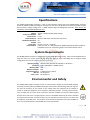
About the K2000 Digital Temperature Controller
Specifications
The SB1000 Seebeck Effect controller is built on and intended to replace the proven SB100 Seebeck Controller
previously offered by MMR Technologies. See Page 9 for the Theory of Operation. This devices provides accurate
Thermo Electric voltage readings from a MMR Seebeck Stage and Refrigerator assembly. These devices are
intended for use with MMR Refrigerators only.
Voltage:
Power Consumption:
Heater Power:
Communications:
Standalone Operation:
Weight:
Dimensions:
Environmental:
115VAC - 220VAC 50/60Hz (Dual Voltage)
30W
0 - 1W
RS232 or USB1.0 (See communications protocol)
No
5Lbs
8.5"(W) x 1.5"(H) x 14.25"(D)
Indoor use only, 5C - 40C Temperature, 2000M Max Altitude, 80% Humidity for
temperatures up to 31 °C decreasing linearly to 50 % Rel humidity at 40 °C.
System Requirements
The SB1000 Seebeck Controller is designed for use with 'MMR Technologies Suite' which must be installed prior to
using this device. For custom control of this device see page 19, please note MMR may not support custom
configurations and in some cases the warranty may be void.
Operating System:
Hardware:
Memory RAM:
Memory Hard Disk:
Peripheral Interface:
Mac OS:
Linux / Unix:
Windows 2000, Windows XP, Windows 7, Windows 8
32BIT / 64BIT INTEL or AMD Processor
2GB
1GB
1x RS232 Serial or USB1.0.
Not Supported
Not Supported
Environmental and Safety
The SB1000 Seebeck Effect controller is built on and intended to replace the proven SB100 Seebeck
Controller previously offered by MMR Technologies. Please observe the following safety warnings. Do
not open the enclosure, do not operate on any voltage other than specified, do not attempt to
service or modify the equipment, do not operate in wet/damp locations. Warning, electrical shock,
injury or death may occur if the device is opened or the earth modified. Use only the cables supplied
with the device and ensure a proper Ground is present. The SB1000 should only be used as intended
and should not be used for any other purpose. Any non-intended use could cause fire, loss of life, loss
of equipment, and bodily harm. User assumes all risk should the equipment be misused, modified, or
use in an unintended manner. Contact MMR for service requirements.
Page |3
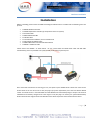
Hardware Installation
Installation
Before proceeding please ensure the MMR Technologies Software Suite is installed and the following items are
present:
•
•
•
•
•
•
•
•
•
1x SB1000 Seebeck Controller
1x K2000 Temperature Controller (If Temperature control is required)
1x AC Power Cable
1x RS232 DB9 Serial Cable
1x USB 3FT Cable
1x User Manual and Software / Driver Installation CD
1x 4FT Refrigerator Ribbon Cable
1x MMR 4-Wire Kelvin Connection Breakout Board
1x SB1000 - K2000 Link Cable
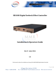
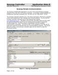
Please connect the SB1000 as shown below. Do not connect both the RS232 Serial cable and USB cable
simultaneously, these are provided as an option should you be short of spare PC ports.
Once connected and with the PC Running you may now power up the SB1000 device. Please first insure the AC
Power switch at the rear of the unit is 'ON' (see page 6 for further information). Press the front button labeled
'Power' to activate the unit. If the USB cable was used Windows will automatically assign a comport. This must be
identified and if necessary changed to be in the range of 1-16. (See page 5 or contact your system administrator)
Please note down the assigned Comm Port Number as this will be required to communicate with the device.
Page |4
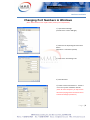
Hardware Installation
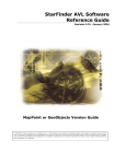
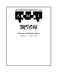
Changing Port Numbers in Windows
(Note: Administrator access maybe needed, contact your IT department)
1/. Open Device Manager.
(Control Panel -> Device Manager)
2/. Select the corresponding Serial Converter
Device.
(Right Click -> Left Click Properties)
3/. Click on the 'Port Settings' Tab.
4/. Click Advanced.
5/. Select a Comm Port between 1 - 16 that is
not in-use by other hardware. Click OK.
(Note: On some computers you may need to
disconnect (unplug) and reconnect the device
to make the changes permanent.)
Page |5
Hardware Installation
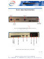
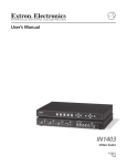
Front / Rear Panel Interface
Note: The Power button must be held for 3 seconds to power down the unit.
*Replace fuse with 3.15A Slow Blow (IEC 127-2 or similar) ONLY.
Page |6
Hardware Installation
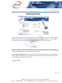
Getting Started
Step 1 - Device ports are easily verified through the welcome screen above, select the port number the SB1000
Temperature Controller is connected to (shown as present next to the SB1000) and press 'Poll'. If the SB1000 is
connected to that port and powered on it will respond with a Device name and Version number.
If the port number is not visible try refreshing the port list by clicking the refresh icon above the "Poll'' buttons. If
this does not resolve the issue try restarting the computer. For further assistance contact your system administrator
and finally the MMR Helpdesk (See contact information on Page 27)
Step 2- Select 'Seebeck Experiment' This will load the Seebeck experiment module, if there is no K2000 present
deselect "K2000' under hardware. This will disable temperature control for all Seebeck experiments. Errors will
occur if K2000 remains selected when not present.
Step3 - Press 'Begin
Page |7
General Operation
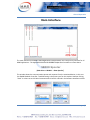
Main Interface
The main interface of the MMR Technologies Suite is shown above, this is the primary container for all
MMR applications. The Applicable items for the SB1000 Temperature Controller are show above.
SB000 Spooler
[Main Suite -> SB1000 - > Show Spooler]
This window shows the communications queue and response from the associated device, in this case
the SB1000 Seebeck Controller. Troubleshooting is the primary use for this window. However clicking
"Send" is a short cut to the' Main Communications Console' outlined in the Software Installation Guide.
Page |8
General Operation
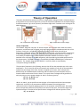
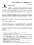
Theory of Operation
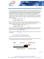
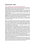
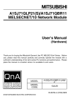
The system described below measures the Thermo- voltage (Seebeck Voltage) of metals and semiconductors.
It also provides the user with the opportunity to study the temperature dependence of the Seebeck Voltage
for different materials , Fig 1 shows a picture of the Seebeck Stage which is attached to the cold stage of the
MMR refrigerator .
Low Temperature Kapton Stage
High Temperature Ceramic Stage
Theory of Operation
The Seebeek Stage has two pairs of thermo couples: one of copper and a metal with known
properties, and the other pair of copper and a metal with properties to be determined. One of the
junctions in each pair is considered a reference junction, and the other the working or
temperature modulated junction. The Stage also has a computer controlled heater, located close
to the working junctions of each pair, and remote from the reference junctions .This heater is
controlled by the MMR Programmable Seebeck Controller SB1000. The Seebeck stage is
attached to the cold stage of an MMR refrigerator, which provides a given stable temperature for
the measurement. The MMR Cold stage is controlled by the MMR K20000 Digital Temperature
Controller. The Seebeck Stage has two outputs: V 1 and V2, which are monitored by
a computer through the SB1000.
The principle of operation is the following. Assume, that all four thermocouples are at the same
temperature . 'Then V1 and V2 will be zero because each member of each pair of thermocouples
compensate the voltage of the other. If power is applied to the heater, then a temperature
difference will be created between the working and the reference junctions because they are
located at different distances from the heater. As a result, thermo-voltages will be generated in
each pair giving non zero output voltages VI and V2. These are given by:
(1). V1 = ε1 ∆ T (P) and
(2). V2 = ε2 ∆ T (P)
Where ε1 and ε2 are the specific thermo-voltages of the sample and known thermocouples
respectively and ∆ T(P) is the temperature difference between the working and the
reference junctions created by applying power P to the computer controlled heater. We expect,
that the temperature difference ∆ T(P) will be the same for both pairs , because the stage has a
symmetrical shape. The value of the specific thermo-voltage of the unknown junction is then:
(3). ε1 = ε2 V1/V2
Page |9
General Operation
However, one should use a small temperature deviation ∆ T in order to obtain representative data
in the temperature domain. Therefore, the values of V 1 and V2 also will be small. Because of this a
direct measurement will not give high accuracy, because of instrumental errors and any undesired
thermo-voltage effects from wires, connectors, etc. These effects can create substantial offset
voltages which, in addition to the temperature drifts and offsets of the input amplifiers, can
contribute a major source of measurement error. These can be eliminated, however, by taking
measurements at two different temperature offsets, using two different power settings, and then
using the difference signal. We show this as follows. The real values of V1 and V2 acquired by the
SB1000 are given by:
(4). V1(P1) = ε1 ∆ T (P1) + ∆ V1 and
(5). V2(P2) = ε2 ∆ T (P2) + ∆ V2
Where ∆ V1 and ∆ V2 are the instrument and extraneous thermal offset voltages, discussed
above, and P1 is the power applied to the heater at the first measurement point. Now, if the heater
power is changed to a new value P2 , we obtain a second pair of values for V 1 and V2:
(6). V1(P2) = ε1 ∆ T (P2) + ∆ V1 and
(7). V2(P2) = ε2 ∆ T (P2) + ∆ V2
The offset voltages ∆V 1 and ∆V2 can be assumed to be independent of power P, because only the
temperature in the immediate neighborhood of the reference and sample junctions change, not
those where these other offset voltages originate.
Subtracting equations (6) and (7) from (4) and (5), respectively, we obtain the true value of ε1 from
the following:
(8). ε1 = ε2 {V1(P1) - V1(P2) } / {(V2(P1) - V2(P2)}
(8) does not include ∆V 1 and ∆V2. The offsets have been removed.
Certain hardware and software precautions have also been implemented to eliminate any possible
electrical coupling between the heater and measurement circuits as well.
P a g e | 10
General Operation
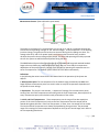
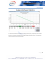
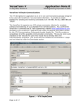
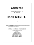
Measurement Process: (Data collected in green areas)
The power or the heater P(t) is changed from zero to level P. V1 and V2 are plotted schematically
to show the corresponding changes of the thermo-voltages , as the temperature of the working
junctions change. The green areas show the time intervals during which readings are taken. The
average value of V1 and V2 for power levels 0 and P are used at the end of every period to
calculate the specific thermo-voltage of the sample. The initial and operating time delays provide
time for the system to stabilize thermally before taking the data.
The MMR Seebeck System allows the temperature of the MMR Cold Stage and attached Seebeck
Stage to be controlled over a wide temperature range. One can thus study the temperature
dependence of the specific thermo- voltage of the samples by repeating the measurements at a
series of temperatures. The Seebeck System allows this to be done automatically .
Definitions.
In the following the various terms used in this Manual and in the operation of the System are
defined.
1. Measurement point. The set temperature for the Seebeck stage provided by the MMR Cold
Stage. Different measurement points are used in order to study the temperature dependence of
the specific thermo-voltage.
2. Experiment. The process that includes: a sequence of settings of the measurement points,
starting from the Initial Temperature and finishing with the Final Temperature; data acquisition at
every measurement point; and calculation and presentation of the results.
3. Initial and Final Temperatures. These temperatures set the range of the data acquisition
process. If the Initial Temperature is less than the Final Temperature then the sample will be
heated during data collection. If the Final Temperature is lower, then the sample will be cooled.
The Initial and Final Temperatures are always displayed during the experiment. The permitted
range of the settings for these temperatures depends on the type of Thermal Stage used . Refer to
the corresponding data sheets.
P a g e | 11
General Operation
4 . Stand-by Temperature. The temperature to which the Seekbeck stage is to be set after the
experiment is completed.
5. Current Temperature. The actual, present temperature of the Cold Stage.
6. Target Temperature .The temperature at which the present activity of the system is targeted. It can
be the Initial Temperature, the Measurement point Temperature, or the Standby Temperature. The
temperature setting process is complete when the Current Temperature is equal to the Target
Temperature.
7. Current Power. The power being applied presently, to the MMR Cold Stage by the 'K2000
MMR Temperature Controller '.
8. Temperature Step. The difference between two successive measurement points.
9. Sweep speed (Ramp Rate). The rate at which the temperature is changed from one
measurement point to the next.
10. Modulation Power. The value of the power applied to the Seebeck stage heater to produce
a temperature gradient across the samples.
11. Initial Time Delay. The waiting period from the time the Cold Stage reaches the measurement
temperature until the system takes the first set of readings. This delay is needed to allow the
Seebeck Stage to reach equilibrium with the Cold Stage.
12. Operating Time Delay. The waiting period from the time the Seebeck Stage heater is turned
on until the second set of readings are taken. This allows a steady state to be reached across the
Seebeck Stage.
13. Reference Thermo-Voltage. The specific thermo voltage (Seebeck Coefficient) of the known
junction; used in the Seebeck Stage as a reference. Since this parameter changes with
temperature, the data acquisition software includes a file with a look -up table to provide the value
which corresponds to that for the set temperature. The Standard MMR Seebeck System is supplied
with a lookup table for Constantan (as the reference material) relative to copper along with
Constantan relative to PdAg .
14. Averaging Parameter .The parameter that defines the number of acquired data readings
made during the measurement time interval which are subsequently averaged at one
measurement point, the parameter can vary from 0 to 7. The actual number of data readings is
calculated as a corresponding power of 2, so a parameter 0 means 2° or one reading, while a
parameter 7 means 27 or 128 readings. MMR Recommends a setting of '2' for most experiments.
P a g e | 12
General Operation
Stage Preparation
1. Stage Installation.
1.1. Remove a Seebeck Stage from the package.
1.2. Put a thin layer of thermal grease on the large Copper plate (Underside).
1.3. Unlock the ZIF connector (if present) on the pre-amplifier board in the vacuum chamber . Using
thumbs on each side of the connecter insert the Seebeck stage fully.
1.4. Affix the Seebeck Stage to The Cold Stage by the spring fasteners .Be extremely careful! Do not
apply any downward force on the refrigerator. Using tweezers to adjust the fasteners during
installation. You can move the Seebeck Stage backwards and forwards by a couple of millimeters to get
the best location.
1.5. Lock the ZIF connector (If present).
1.6. Install the cover on the vacuum chamber.
2.
Connect the Ribbon cable from the Chamber to the SB1000, if a K2000 is present for temperature
control ensure the Link Ribbon Cable is installed from the SB1000 to the K2000
3.
If you are going to use the system at temperatures below ambient, you should also install all
system components required for cooling according to the MMR Refrigerators Manual.
P a g e | 13
General Operation
Sample Preparation
The MMR Seebeck System can be used for measurement of the Seebeck coefficient of a wide range of
different conductive substances, metals, organic conductors and semiconductors. Samples should be in
the form of a thin strip or wire to be installed on the Seebeck Stage. The actual dimensions and the
shape of samples are not critical, but should be considerably smaller than the Seebeck stage itself. We
recommend that the width of the samples not exceed 1mm (40 mils), and the length 5 mm (200 mils).
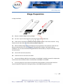
For proper installation of the samples, good electrical and thermal contacts must be provided at both
ends of the sample to the Seebeck Stage Areas (Shown Below) The unknown sample should be installed
to the left or the Seebeck Stage center, the reference sample to the right.
Do not switch these locations, otherwise you will get completely incorrect results! For attaching the
samples to copper surfaces, one can either use regular soldering alloys, or electrically/thermally
conductive cement or epoxy. The bonding substance should be able to withstand the temperature range
of the proposed measurements. Materials of high specific resistivity and low thermal conductivity
should not be used. The resistance of the sample plus the bonding material to the Seebeck Stage should
be less than 100Kohm.
Install the unknown sample first, using the bonding material of your choice , The working
junction should be located as close as possible to the slot that separates the two copper surfaces of the
unknown and reference samples . (see page 10) The location of the other end of the sample is much less
critical. If the sample cannot be formed or folded, attach it at any convenient point on the copperplate
which is common to the unknown and reference samples, and as close to the center as possible.
Install the reference sample in a similar manner. Cut approximately 5 millimeters (0.2") of the
reference material wire supplied with the System, For the standard Seebeck System version this is a
wire of Constantan . Attach one end of the wire piece to the copper plate which is common to both
samples. Use the same point as for the unknown sample. The unknown and reference samples should
have direct thermal contact in this point. Attach the other end of the reference sample taking into
account the same considerations, as for tested sample .The working junctions of both samples should
have symmetrical locations relative to the stage heater. Finally, using an appropriate fluid, clean the
Seebeck Stage of possible surface contamination. We recommend the use of Freon's and/or methyl or
ethyl alcohol. Any cleaning materials used must be non-conductive,
Notice: Be very careful while mounting the samples, bad electrical or thermal contacts, asymmetrical
location of the working junctions; and surface contamination can cause serious measurement errors
P a g e | 14
General Operation
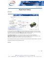
Experiment Setup
New Project
As mentioned in the Seebeck Definitions on Page 12 the Experiment parameters can now be entered.
If no K2000 Temperature Controller is present select 'Skip Temperature Settings' this will carry out the
experiment at Ambient Temperature (300K will be used for all calculations).
Sample Mounting Stage: Select the appropriate stage type that the sample is mounted on.
High Impedance Input: Select the appropriate Impedance Setting that relates to the Amplifier in use.
Gain: Select the appropriate Gain value that relates to the Amplifier in use.
Note: Impedance and Gain settings are indicated on the Amplifier board inside the chamber. The correct
settings must be used or erroneous data will result.
Click 'OK'
P a g e | 15
General Operation
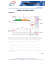
Seebeck Software Layout
Experiment View
Before selecting 'Start' check the voltages and temperature data (If a K2000 is present), check the
SB1000 status in the 'Experiment Setup' box to verify proper communication ('Ready'). As shown above
the voltages are close to 0 and equal. Improper material mounting will cause erroneous voltages.
If 'Auto Standby' was selected the 'K2000 Temperature Controller' will first set the Standby
Temperature.
Selecting start will begin the Automated Data Collection process, the progress and status will be shown
on the right hand side of the Experiment window. If the experiment is 'Started' before the standby
temperature is reached the experiment will wait until the temperature is reached and then begin
automatically.
If a K2000 Temperature Controller is present, the temperature plot will automatically begin recording
temperature data.
P a g e | 16
General Operation
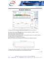
Seebeck Software
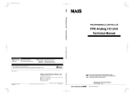
The above 'Complete' Experiment shows the data collected, the user has the option of :
1/. Saving the data to the internal database to retrieve later (Main Suite -> SB1000 -> Open).
2/. Printing the Data (in Data View click 'Print ')
3/. Printing the Plot (in Graph View click 'Print')
4/. Exporting Data to Comma Separated Values (in Data View click 'Export .csv') for further analysis in
third party software such as Microsoft Excel.
5/. Viewing statistics, (in Data View click 'Statistics')
Note: Some options are only available when the Experiment has completed successfully.
The above plot shows the Temperature Control during the Seebeck Experiment, this data can be
printed from within the K2000 Temperature Graph Window if needed.
P a g e | 17
General Operation
Seebeck Software Statistics
The above Statistical Results view displays the Average Values at every Temperature point. Standard
Deviation is also present along with the Percentage Change and Min Max Values. If no temperature
control is present only 1 point will be plotted.
P a g e | 18
General Operation
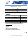
Communications Protocol
Main Communications Type:
Communications Interfaces:
Serial Settings:
Handshaking:
Echo:
Bus Pairing:
Hardware CTS Timeout:
Data Format:
Serial
RS232, USB1.0
9600,N,8,1
Hardware RTS/CTS
Yes
Parallel
1000ms
ASCII / Plain Text
System Commands
Command
SM
GV
SH
N
O
Format
SMX
GVX
SHXXX
N1
O1
Example
SM1 (1-7) Averaging Parameter 2^n Readings
GV1 (1 or 2) Valid when unit is in standby.
SH300 (300mW)
Description
Start Measurement
Get Voltage
Set Heater
Get Device ID
Power Down Unit
Note: Sending command SMx starts constant measurement at desired average rate.
Communications & Byte Order
Command Example: 'SM2' (Starts measurement at 2^2 = 4 readings per average)
1/. Set RTS High
2/. Wait for CTS
3/. Send 'S' as a Character (VB Example on Next Page)
4/. Send 'M' as a Character (VB Example on Next Page)
5/. Send Average as a 2-Byte Word (Highbyte First, Lowbyte Second)
6/. Set RTS Low
P a g e | 19
General Operation
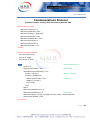
Communications Protocol
Visual Basic Example - Sending a start measurement command. 'SM2'
Private Sub Form_Load()
MSComm1.CommPort = 2
MSComm1.DTREnable = False
MSComm1.Settings = "9600,N,8,1"
MSComm1.RTSEnable = False
MSComm1.OutBufferSize = 1024
MSComm1.RThreshold = 1
MSComm1.SThreshold = 0
MSComm1.PortOpen = True
End Sub
Function StartMeasurement()
Dim command As Long
Dim var As Integer
Dim counter As String
val = 2
'Start Measurement 2^2
counter = 0
MSComm1.RTSEnable = True
'Set RTS High
While MSComm1.CTSHolding <> True
counter = counter + 1
'Wait for CTS Signal
If counter > 200000 Then
MSComm1.RTSEnable = False
'Reset RTS
MsgBox ("Time Out")
Exit Function
End If
Wend
MSComm1.OutBufferCount = 0
MSComm1.InBufferCount = 0
'Clear Buffers
MSComm1.Output = Chr$(S) + Chr$(M) + Chr$(val / 256) + Chr$(val Mod 256)
MSComm1.RTSEnable = False
End Function
P a g e | 20
Troubleshooting
Troubleshooting
Symptom Solution
Cannot Communicate with SB1000 Ensure Unit is properly connected and powered
on. Press Reset, Check that the device is connected
to the correct Communications Port and the
drivers are successfully loaded.
No Lights on SB1000 Ensure Unit is plugged into an AC Power source,
the rear power switch is on. Check Fuse.
Readings are unstable Check refrigerator is under vacuum.
Check sample mounting quality
Refrigerator doesn't Cool or Heat Refer to Refrigerator Operators Manual, check for
damage to refrigerator.
Temperature Accuracy has degraded Return Refrigerator to MMR for Sensor service.
Software has an Error message Contact MMR helpdesk
For all other errors or issues please contact the MMR Help Desk (See Page 22)
P a g e | 21
Troubleshooting
Help Desk and MMR Contact Information
Help Desk Email Address:
[email protected]
Bug Reporting:
[email protected]
Technical Support Email Address:
[email protected]
Sales & Marketing Department:
[email protected]
Help Desk:
Office Hours:
Physical Address:
+1 650 962 9620
7:30am - 5:00pm (Pacific Time)
Monday - Friday
1400 North Shoreline Blvd, Suite A5
Mountain View, California 94043
USA
P a g e | 22
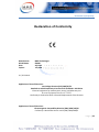
Declaration of Conformity
Declaration of Conformity
Manufacturer:
Model Name:
Date:
Expires:
MMR Technologies
SB1000
July 2014
July 2018
UL / IEC 61010
Application of Council Directives:
Low Voltage Directive (LVD) 2006/95/EC
Standards to which Conformity is Declared: IEC EN 61010-1 3rd Edition
Electrical equipment for measurement, control, and laboratory use
Pressure Equipment Directive (97/23/EC)
Conformity is declared to Annex I Essential Requirements of the Directive
Application of Council Directives:
Electromagnetic Compatibility Directive (EMC) 2004/108/EC
Conformity is declared to Annex I and II (EMC) 2004/108/EC
P a g e | 23