1
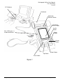
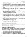
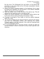
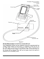
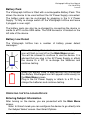
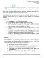
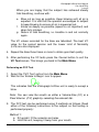
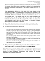
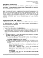
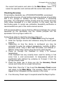
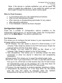
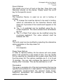
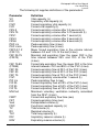
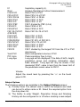
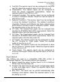
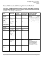
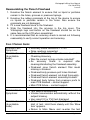
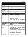
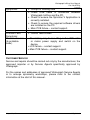
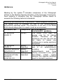
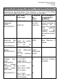
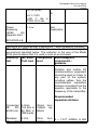
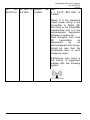
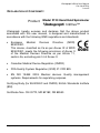
Model 2120 Hand Held Spirometer Vitalograph In2itive™ User Manual l Page 1 of 45 DT_0006-6 Vitalograph Ltd. Maids Moreton Buckingham MK18 1SW England Tel: +44 (0) 1280 827110 Fax: +44 (0) 1280 823302 e- mail: [email protected] Vitalograph Inc. 13310 West 99th Street Lenexa Kansas 66215 USA Tel: (913) 888 4221 Fax: (913) 888 4259 e-mail: [email protected] Vitalograph GmbH Rellinger Straße 64a D-20257 Hamburg Germany Tel: (040) 547391-0 Fax: (040) 547391-40 e-mail: [email protected] Vitalograph (Ireland) Ltd. Gort Road Business Park Ennis Co Clare Ireland Tel: (065) 6864100 Fax: (065) 6829289 e-mail: [email protected] Internet: www.vitalograph.co.uk © Copyright Vitalograph 2009, 2010 & 2011 Current Edition (Issue 5) Cat. No. 07514 Vitalograph is a registered trademark Page 2 of 45 DT_0006-6 Table of Contents DESCRIPTION OF THE VITALOGRAPH DEVICE 5 FEATURES OF THE VITALOGRAPH DEVICE 7 GETTING THE VITALOGRAPH DEVICE READY FOR USE 7 OPERATING THE DEVICE WITH SPIROTRAC V 8 CONNECTING THE REMOTE FLOWHEAD 8 POWER MANAGEMENT IN THE VITALOGRAPH DEVICE BATTERY PACK BATTERY LOW DETECT OPERATING THE VITALOGRAPH DEVICE ENTERING SUBJECT INFORMATION PERFORMING A TEST SESSION Checks to Make before Performing a Test Session Performing a VC Test Performing an FVC Test SAVING THE TEST SESSION. PERFORMING A POST TEST SESSION PERMANENT STORAGE OF PRE-TEST SESSIONS PRINTING AND VIEWING THE TEST SESSION CLEAR RESULTS CHECKING ACCURACY When to Check Accuracy CONFIGURATION OPTIONS Test Preferences Database Calibration Settings Subject Options Smart Options Report Options CLEANING INSTRUCTIONS CLEANING AND DISINFECTING THE VITALOGRAPH IN2ITIVE REMOVING THE FLEISCH FLOWHEAD REASSEMBLING THE FLEISCH FLOWHEAD Page 3 of 45 10 11 11 11 11 12 12 12 14 17 17 18 18 19 20 21 21 21 22 22 23 26 27 27 30 30 32 33 DT_0006-6 FAULT FINDING GUIDE 33 CUSTOMER SERVICE 35 CONSUMABLES AND ACCESSORIES 36 EXPLANATION OF SYMBOLS 36 TECHNICAL SPECIFICATIONS 37 CE NOTICE 38 FDA NOTICE 43 DECLARATION OF CONFORMITY 44 GUARANTEE 45 Page 4 of 45 DT_0006-6 Vitalograph In2itive User Manual Cat. No. 07514 Issue 5 DESCRIPTION OF THE VITALOGRAPH DEVICE The Vitalograph In2itive is a handheld spirometer designed for use by trained professionals in the doctor’s office, clinic, hospital department, etc. for measuring and archiving tests on human subjects. Demographic data are uploaded or entered via a keypad and stored, together with spirometry test data. Current test data can be viewed on the LCD and printed and downloaded to a PC. There are a variety of backup and other configuration options. Information about the software can be obtained from the About box. This information can be used if any queries are made to Vitalograph or a service agent. To access the About box: 1. Press the Configuration button from the Main Menu. 2. Press the About button. The main components for the Vitalograph In2itive are shown in Figure 1. Page 5 of 45 DT_0006-6 Vitalograph In2itive User Manual Cat. No. 07514 Issue 5 PC Software Flowhead Flowhead Release Button LCD/Touch panel Display On/Off Button Mini USB ports in cradle and device Stylus Holder Cancel Button Down Button Up Button Enter Button Figure 1 Page 6 of 45 DT_0006-6 Vitalograph In2itive User Manual Cat. No. 07514 Issue 5 FEATURES OF THE VITALOGRAPH DEVICE The Vitalograph In2itive features include: • • • • • • • • • • • • • • • • • • • • Fleisch pneumotachograph Integral and removable flowhead Touch screen color display or buttons Clear sounds for audio feedback Choice of child incentive displays Fully customizable report format Desktop cradle supplied as standard Optional cradle for connection to A4 USB printers (PCL compatible) Optional communications cradles Automatic download of new subjects 10,000 subject test memory Automatic upload of all test data Pre/post bronchodilator comparison Choice of predicted values and languages Diagnostic interpretation options Lung age for adults and adolescents Real-time test quality prompts Vitalograph PC software included Stylus Can enter subject details on device GETTING THE VITALOGRAPH DEVICE READY FOR USE 1. Place the Spirotrac V CD-ROM into the CD drive. The installation program starts automatically after a short period of time and leads you through the installation. The following are the most important points of the installation procedure. 2. If you do not already have Acrobat reader installed then select ‘Install Acrobat Reader’. You will require it to read the User Manual and any Test Reports that you have chosen to ‘Print’ as a PDF document. 3. Spirotrac V can import and export to your practice software, if your practice software supports one of the communications standards in Page 7 of 45 DT_0006-6 Vitalograph In2itive User Manual Cat. No. 07514 Issue 5 Spirotrac V. Administration rights on your PC are required. This can also be installed later. 4. For security reasons it is necessary during installation to enter an activation key and licence key. These are available on the CD cover. 5. When installation is complete remove the CD and keep in a safe place. 6. Connect one end of the USB cable into an available USB connection on your computer and the other end into the USB connection on the side of the cradle. The cable can also be connected into the left side of the Vitalograph In2itive device. The device is powered via the USB cable. 7. Place the In2itive device into the cradle. 8. The Vitalograph In2itive device may also be powered using the purpose-built low voltage power supply unit with which it is supplied. Attempted use with other power sources may cause irreparable damage and invalidate the warranty. The output from the power supply is 5 volts DC. Connect the mini USB connector from the power supply into the USB socket on the side of the unit or into the cradle. Plug the mains plug into a suitable socket. 9. Operate the On/Off switch on the front face of the instrument and the Vitalograph In2itive is ready for use. 10. For portability the Vitalograph In2itive comes fitted with rechargeable batteries, which allows the device to be used for a period of time without the mains connected. OPERATING THE DEVICE WITH SPIROTRAC V Refer to the Help Files on Spirotrac V for information on operating the Vitalograph In2itive with Spirotrac V. CONNECTING THE REMOTE FLOWHEAD The flowhead on the Vitalograph In2itive can be set up to work remotely from the device. This can be done as follows (see figure 2): 1. Hold the device body firmly in your left hand. 2. Hold the flowhead with your right hand, at the same time press and hold the button firmly on the front of the fleisch flowhead. 3. Slide the flowhead away from the device from left to right. 4. Attach the device cap in the same position as the flowhead was attached. This is done by sliding the flowhead into the grooves in Page 8 of 45 DT_0006-6 Vitalograph In2itive User Manual Cat. No. 07514 Issue 5 the top cover. The Vitalograph font and button on the device cap should be on the same face as the LCD when assembled. Ensure this is fully pushed in. 5. Attach the remote flowhead adaptor to the flowhead. This is done by sliding the flowhead into the grooves in the remote flowhead adaptor. Ensure this is fully pushed in. 6. Open the rubber cover on the left side of the device cap. This will expose the two pressure ports on the device cap. 7. Attach the remote flowhead to the Vitalograph In2itive device cap by the dual silicone tubing (Flowhead Connection Tube). 8. A recess is provided on the cradle to hold the remote flowhead when not in use. 9. The remote flowhead can be disconnected by removing the device cap from the Vitalograph In2itive, and removing the remote flowhead adaptor from the flowhead. Then slide the flowhead back onto the Vitalograph In2itive. 10. It is recommended that an accuracy check is carried out after the remote flowhead is fitted or removed to verify correct operation and accuracy. Page 9 of 45 DT_0006-6 Vitalograph In2itive User Manual Cat. No. 07514 Issue 5 Device Cap Release Button Device Cap Rubber Cover Flowhead Release Button Flowhead Remote Flowhead Adaptor Flowhead Connection Tube Figure 2 POWER MANAGEMENT IN THE VITALOGRAPH DEVICE The Vitalograph In2itive can be powered using the purpose-built low voltage Power Supply unit with which it is supplied or from the PC via the USB cable or from the internal Battery Pack. When powered from the low voltage Power Supply or the PC the LED on the front face on the device will be orange. The LED will be green when the device is powered from the Battery Pack. Page 10 of 45 DT_0006-6 Vitalograph In2itive User Manual Cat. No. 07514 Issue 5 Battery Pack The Vitalograph In2itive is fitted with a rechargeable Battery Pack. This allows the device to be used without the 5V Power Supply connected. The battery pack can be re-charged by plugging in the 5 V Power Supply. To fully re-charge switch off the Vitalograph In2itive and leave it plugged in over-night. The battery pack can also be re-charged by connecting the device or cradle to a PC via the USB cable. The USB connector is located on the left side of the device. Battery Low Detect The Vitalograph In2itive has a number of battery power detect messages: When the Battery Pack starts to run low the Battery Low icon will flash on and off on the Main Menu screen. You will be allowed to continue to use the device. It is advised that you plug in the 5V Power Supply or attach the device to a PC to re-charge the batteries and continue testing. When the Battery Pack is approaching fully discharged the Battery Discharged icon will appear continuously on the Main Menu screen. Plug in the 5V Power Supply or attach to a PC to recharge the batteries and continue testing. OPERATING THE VITALOGRAPH DEVICE Entering Subject Information After turning on the device, you are presented with the Main Menu screen. Note: In Smart mode you can configure the device to go directly into the Subject Select screen. See Smart Options. Page 11 of 45 DT_0006-6 Vitalograph In2itive User Manual Cat. No. 07514 Issue 5 1. Select the Subject button, to bring you into the Select Subject screen. 2. You can list the subjects saved on the device by selecting either the Name or ID tab. 3. To select a subject from the database, hi-light the subject. This will allow you the view the subject details. Select Enter to make the subject current. 4. To create a new subject, select the New tab. Enter the subject details by hi-lighting the required field and typing in the information using the touch panel keypad. Additional subject information may also be entered by selecting the Optional tab. Press the Enter button to save the subject to the database and return to the Home Menu. Note: The current subject surname and forename will be displayed on the bottom left hand corner of the screen. If the subject name is not entered then the subject ID will be displayed. If the subject has test session results associated with it then the subject name and ID will appear in black. If there are no test session results then the subject name and ID will appear in grey. Performing a Test Session Checks to Make before Performing a Test Session Before starting a test session, there are a number of checks which should be made: 1. Ensure that the accuracy of the Vitalograph In2itive unit was checked recently. (Refer to the section on Checking Accuracy) 2. Ensure a subject is selected (subject ID or name will appear on the status bar at the bottom of the Main Menu) and the required demographic information is entered for the subject. 3. Fit a disposable BVF or SafeTway mouthpiece. The use of a disposable noseclip is also recommended. Performing a VC Test Perform the VC test as follows: 1. Select the ‘VC Test’ option from the Main Menu. 2. Wait for the ‘Exhale to Begin’ icon to appear. Page 12 of 45 DT_0006-6 Vitalograph In2itive User Manual Cat. No. 07514 Issue 5 This indicates that the Vitalograph In2itive unit is ready to accept a blow. Note: You can view the results as either a Volume/time graph or a Volume bar graph by selecting the relevant tab. The VC test can be performed using two methods. Read either of the following instructions to the subject so that testing is performed properly: Method 1: a. Sit upright, fit the nose clip and relax. b. Hold the unit, keeping it away from your mouth. c. Inhale as deeply as possible, hold your breath, then insert the mouthpiece carefully into your mouth, not like a trumpet, but clamping it gently between your teeth. d. Seal your lips around the mouthpiece and keep your tongue down. e. Blow out as long as possible. Keep blowing until all air is expelled. It is vital that the operator encourages to subject to keep blowing to ensure all air is squeezed out. f. Listen for two beeps. This indicates that Vitalograph In2itive is ready for the next blow. Method 2: Note: Method 2 can only be used when the Volume/Time (V/t) graph is selected as the display option. This method cannot be used when the Volume bar graph is selected as the display. a. Sit upright, fit the noseclip and relax. b. Insert the mouthpiece carefully into your mouth, not like a trumpet, but clamping it gently between your teeth. c. Seal your lips around the mouthpiece and keep your tongue down. d. Breathe in and out normally. This is tidal breathing. Page 13 of 45 DT_0006-6 Vitalograph In2itive User Manual Cat. No. 07514 Issue 5 When you are happy that the subject has achieved steady tidal breathing, continue with: e. Blow out as long as possible. Keep blowing until all air is expelled. It is vital that the operator encourages to subject to keep blowing to ensure all air is squeezed out. f. Inhale as deeply as possible (speed is not important) and when fully inhaled. g. Return to tidal breathing, i.e. breathe in and out normally again. The VC values recorded for the blow are tabulated. The best VC value for the current session and the Lower Limit of Normality (LLN) are also displayed. 4. Repeat the blow three times or more to obtain good test quality. 5. After performing the VC tests press the Cancel button to exit the VC Test screen. This brings you back to the Main Menu. Performing an FVC Test 1. Select the ‘FVC Test’ option from the Main Menu. 2. Wait for the ‘Exhale to Begin’ icon to appear. This indicates that the Vitalograph In2itive unit is ready to accept a blow. Note: You can view the results as either a Volume/time (V/t) or a Flow/Volume (F/V) graph by selecting the relevant tab. 3. The FVC test can be performed using 2 methods as follows. Read either of the following instructions to the subject so that testing is performed properly: Method 1: a. Sit upright, fit the noseclip and relax. b. Hold the unit, keeping it away from your mouth. Page 14 of 45 DT_0006-6 Vitalograph In2itive User Manual Cat. No. 07514 Issue 5 c. Inhale as deeply as possible, hold your breath, then insert the mouthpiece carefully into your mouth, not like a trumpet, but clamping it gently between your teeth. d. Seal your lips around the mouthpiece and keep your tongue down. e. Blow out as long as possible. Keep blowing for at least 6 seconds. (From the very beginning of the blow the operator should encourage the subject to keep going in a lively fashion. Keep eye contact with the subject) f. If inspiratory indices are selected, then inhale as quickly as possible. g. Listen for two beeps. This indicates that Vitalograph In2itive is ready for the next blow. Method 2: a. Sit upright, fit the noseclip and relax. b. Insert the mouthpiece carefully into your mouth, not like a trumpet, but clamping it gently between your teeth. c. Seal your lips around the mouthpiece and keep your tongue down. d. Breathe in and out normally. This is called tidal breathing. When you are happy that the subject has achieved steady tidal breathing, continue with: e. Inhale as deeply as possible f. Blow out as long as possible. Keep blowing for at least 6 seconds. (From the very beginning of the blow the operator should encourage the subject to keep going in a lively fashion. Keep eye contact with the subject) g. Inhale fully as quickly as possible h. Return to tidal breathing, i.e. breathe in and out normally again. 4. The FVC, FEV1 and PEF values recorded for the blow are tabulated. The best FVC, FEV1 and PEF for the current session are displayed. The test quality (QA) is shown at the bottom of the test screen. Page 15 of 45 DT_0006-6 Vitalograph In2itive User Manual Cat. No. 07514 Issue 5 The best 3 tests performed and the Test Grade are shown in the V/t screen. Each test series is graded in relation to its repeatability between acceptable manoeuvres. The quality Grades are A, B, C, D and F. The repeatability (Within) of FVC and FEV1 are shown in the Information screen. The repeatability information is displayed if at least two tests are performed. I Bars on the F/V graph are shown for FEF25, FEF 50 and FEF75. An I Bar for FVC is also shown on the Volume axis. The upper mark on the I Bars indicates the predicted value for the subject. The lower mark on the I Bar indicates the LLN value for the subject. The I Bars are based on the predicted sets and will be shown if sufficient subject demographics information is entered. 5. Repeat the blow three times or more to obtain good test quality. 6. To view results select the results tab. - You can view the results for each blow by selecting the up/down arrows on the top right of the screen. If any of the parameters are below the Lower Limit of Normality (LLN), then they will be displayed in red, provided the subject age, height and gender are entered. - To view the graph of the blow select the graph button on the bottom of the screen. - You can choose to manually accept or reject a blow using the drop down list for User Acceptability. - You can view the trend graph by selecting the trend button on the bottom left of the screen. 7. After performing the FVC tests press the Cancel button to exit the FVC Test screen. This brings you back to the Main Menu. Note: The measurements obtained from a lung function test form part of the various findings of a physician in the detection, diagnosis and control of chest diseases. Spirometry may support or exclude diagnosis, but it cannot make one. Page 16 of 45 DT_0006-6 Vitalograph In2itive User Manual Cat. No. 07514 Issue 5 Saving the Test Session. The test session is saved to the database by following the on-screen messages. These messages appear when a new subject, an accuracy check or POST mode is selected. Note: If a micro SD card is inserted into the micro SD connector at the right side of the device, then all test blows and not just the best three will be saved to the micro SD card. Results are saved as per the format outlined in the European Respiratory Journal, 2005; 26: Pages 319-338: ATS/ERS Task Force: Standardisation of Lung Function Testing. Performing a Post Test Session A Post test session can be performed on an FVC test session following the administration of drugs. Post drug delivery performance is measured versus pre delivery. To perform a Post test: 1. Select ‘Post Mode’ from the Main Menu. 2. If you want to perform a Post Test on the Pre-test Session just performed select ‘Perform Post test on Current Subject’. This will return you to the test screen. The text Post Mode will appear on the graph. 3. If you wish to perform a Post Test on a different subject or Pre-test: a. Select ‘Select Subject from List’. b. A message ‘Warning! Current test session will end. Do you want to save the test session?’ will appear. Select Yes and the Select Subject screen will appear. c. Select the subject you wish to perform the Post test on, and the Select Test Session screen will appear. Select the test session. Note: The letters P, V or F or a combination of these will appear after the session ID. If the letter P appears then a POST test session has already been performed on this pre session. If V appears then a VC test has been done as part of the pre-session. If F appears then and FVC test has been performed as part of the pre-session. Page 17 of 45 DT_0006-6 Vitalograph In2itive User Manual Cat. No. 07514 Issue 5 d. Press ‘Enter’ to bring you to the test screen. The text Post Mode will appear on the graph. 4. Perform the Post FVC test as outlined in section Performing a Test Session. Permanent Storage of Pre-Test Sessions The Post Mode screen also gives you the option to save and recall test sessions to and from a permanent storage location on the device. This permanent storage does not get deleted when test sessions are sent to Spirotrac V or printed. To access this option select ‘Permanent Storage’. The Permanent Storage screen gives you four options: 1) Save Test to Permanent Storage: When this option is selected a message will appear informing you of the memory location where the test session will be saved. There are nine permanent memory locations on the Vitalograph In2itive. 2) Load Test from Permanent Storage: When this option is selected the list of permanent pre-test sessions will appear. Select the required pre-test session from the list and select enter to bring you into the Post Mode screen. 3) Delete Test from Permanent Storage: When this option is selected the list of permanent pre-test sessions will appear. Select the Test session you wish to delete and press enter. This location will then be marked as ‘Empty’. 4) Delete all Tests from Permanent Storage. When this option is selected a warning message will appear:- ‘Do you want to delete all tests stored in permanent storage?’. Press enter to delete all tests. Printing and Viewing the Test Session You can print the current test session for the subject by selecting ‘Print’ from the FVC Test screen. The Vitalograph In2itive can be connected through the USB port at the side of the unit or from the cradle to the Vitalograph Reports Utility, so that the report can be written to a PC. By using the optional Print Cradle the Vitalograph In2itive can also be connected to an external PCL compatible printer. Page 18 of 45 DT_0006-6 Vitalograph In2itive User Manual Cat. No. 07514 Issue 5 The information printed on the session report and also the reports method (Vitalograph Reports or External Printer) can be configured to suit individual requirements. Refer to section on Report Options. You can also select the Report option from the Main Menu. If you already have a Current Subject selected the following options are available: a) Current Test Session: You can select to print the current test session. To print the current session, select the print icon at the top of the session results screen. b) Select Test Session: You can select a test session for the current subject. To print the session, select the print icon at the top of the session results screen. c) All Test Sessions: You can print all test sessions for the current subject. You can also print Test Session(s) from a different subject in the database. This is done by selecting the ‘Select’ tab in the View and Report screen. The following options are available: a) Select Test Session: You must first select a subject from the database, and then select a test session for that subject. To print the selected session, select the print icon at the top of the session results screen. b) All Test Sessions: This will print all test sessions performed on a subject. When you select this option you must first select a subject from the database. c) All Test Sessions Between…: This will print all sessions stored on the device between specified dates. You must first select the dates. The default test parameters on the report will vary according to regional requirements. Test parameters can be configured to suit individual requirements. Refer to section on Parameters. Clear Results If you wish to delete the current session you can do this as follows: 1. Select the ‘Clear’ option from the Main Menu. 2. A message will appear ‘Warning! Current Test Session Will End. Do you want to save the test session?’ Select ‘Yes’ to save the current test session and return to the Main Menu. Select ‘No’ to not save Page 19 of 45 DT_0006-6 Vitalograph In2itive User Manual Cat. No. 07514 Issue 5 the current test session and return to the Main Menu. Select ‘C’ to cancel the operation and continue with the current test session. Checking Accuracy All spirometry standards (e.g. ATS/ERS/BTS/ANZRS) recommend checking the accuracy of lung function measuring devices at least daily with a 3-L syringe to validate that the instrument is measuring accurately. The Vitalograph In2itive should never be outside accuracy limits unless damaged or in a fault condition. In this event, see the fault-finding guide. In normal use, calibration traceability certification is recommended as a part of the routine annual service. ATS recommendations require that the difference between the volume measured by the spirometer and the volume pumped into the spirometer from a syringe is within 3%. Follow these steps to check the accuracy of the unit. 1. Select Accuracy Check from the Main Menu using the keypad. 2. Enter the Syringe volume and reference using the touch panel keypad. 3. Depending on how the device is configured you may be prompted to enter the ambient temperature, humidity (0-99%), pressure (25-31 inHg or 850-1060 hPa-mbar) and altitude (18500m). Enter these values using the touch panel keypad. 4. Pump air through the flowhead to bring it to ambient temperature. If the flowhead has very recently been used for testing or has come from a cold environment, its temperature should be equilibrated with ambient by pumping air through it from the syringe several times. 5. Press the ‘Enter’ key to bring you into the Accuracy Check screen and follow the on-screen instructions. Note: Note: Press the ‘C’ key to exit the Accuracy Check screen and return to the Main Menu. The accuracy check will not be logged to the Vitalograph In2itive memory in this case. 6. If an Accuracy Check report is required select the Report option. Page 20 of 45 DT_0006-6 Vitalograph In2itive User Manual Cat. No. 07514 Issue 5 Note: If the device is outside calibration you will be given the option to update the calibration. If you select this option you will be brought through the accuracy check routine again. When to Check Accuracy • • • • • In accordance with your own established procedures After annual maintenance checks After cleaning or disassembling spirometer for any reason After adjusting calibration If the flowhead or device has been dropped. Configuration Options There are a number of Configuration options available on the Vitalograph In2itive device. To access these, select the ‘Configuration’ option on the Main Menu. The options available are: Test Preferences This allows you to configure the test screen to your requirements. The following options are available: d) FVC Display: You can select to show F/V (Flow-Volume) or V/T (Volume-Time) Graph by default in the FVC test screen. Select the required option from the drop down menu. e) VC Display: You can select to show the Bar Graph or V/T (Volume-Time) Graph by default in the VC test screen. f) Test Acceptance: This allows you to manually accept the tests performed, or allow the device to determine test acceptability (automatic). g) Graph Scale: This allows you to select the default graph scale. h) Post VC Test: If you have done a VC test in a pre test session and then go to do a Post test on that session then the VC test screen will automatically come up. By selecting ‘off’ in the drop down list you will be brought directly into the FVC test screen. i) Posture: You can select to no posture selected, standing or sitting. j) Temperature: By selecting ‘on’ in the drop down list, the device give the user the option to manually enter the ambient temperature as they go into the VC or FVC test screens. Page 21 of 45 DT_0006-6 Vitalograph In2itive User Manual Cat. No. 07514 Issue 5 Database This allows you to manage the available memory on the device. The Management tab tells you how much subject and test session memory has been used up. As with all memory after a period of time and repeated use the memory becomes fragmented. Because of this the total available memory is not being used. In order to correct this, select the Defragment option. This process may take several minutes to complete. The Deletion tab allows the user to delete sessions. By selecting the relevant box the session will be deleted from the device after being Printed. (Either a print to an external printer or sent to Vitalograph Reports). You are also given the option to ‘Select Test Session(s)’ for deletion, or ‘Delete Subject(s)’ from the device by pressing the relevant button using the touch panel LCD. Calibration The Vitalograph In2itive should never be outside accuracy limits unless damaged or in a fault condition. In this event, see the fault-finding guide. In normal use, calibration traceability certification is recommended as a part of the routine annual service. Select the Calibration Options menu. You are presented with three options: - Precision Syringe - Calibration Precision Syringe: b) Select Precision Syringe from the Calibration screen. c) Select the volume of the calibrated syringe you are using from the drop down list. d) Enter the syringe reference number using the touch panel keypad. e) Press ‘Enter’ to save the new volume entered and return to the Calibration screen. Press ‘C’ to cancel the changes made and return to the Calibration screen. Calibration a) Select Calibration from the Calibration screen. Page 22 of 45 DT_0006-6 Vitalograph In2itive User Manual Cat. No. 07514 Issue 5 b) Pump air through the flowhead to bring it to ambient temperature. If the flowhead has very recently been used for testing or has come from a cold environment, its temperature should be equilibrated with ambient by pumping air through it from the syringe several times. c) Press the ‘Enter’ key to bring you into the Calibration screen and follow the on-screen instructions. Note: Press the ‘C’ key to exit the Calibration screen. d) If a Calibration report is required select the Report option. Settings This allows you to adjust the settings of the device. The following options are available in the Device Settings screen: - Date/Time - Sound Options - Incentive - Units - Power Save Options - Parameters - Volume Date/Time There are two tabs in this screen for the time and date. a) In order to change the time, scroll the hours and minutes to the required settings by pressing the arrows on the touch panel LCD. b) The time format can be changed from 24 hour to 12 hour by switching On/Off the ’24 Hour Format’ option. c) In order to change the date, scroll the day, month and year to the required settings by pressing the arrows on the touch panel LCD. d) To modify the Date Format select the required option from the drop done list. The options available are: DD/MM/YYYY MM/DD/YYYY YYYY/MM/DD Page 23 of 45 DT_0006-6 Vitalograph In2itive User Manual Cat. No. 07514 Issue 5 Sound Options This allows you to turn off and on the Key, Flow, Error and Welcome sounds on the device. Simply select the on/off key for the specific sound. Incentive The Incentive Device is used as an aid in testing of children. a) To change the incentive device to be used in testing, select an alternative for the Incentive Device drop down list. A preview of the incentive will appear on the screen. b) The % of predicted can be modified using the onscreen keyboard. The value entered must be between 80-150. c) The % of Best Test value can be modified using the on-screen keyboard. The value entered must be between 80-150. Units The units used can be modified by selecting the alternative option available on the drop down list: - Metric - US (Imperial) Power Save Options In order to improve battery life the device will auto power down if left unused for a set length of time. You can modify this by selecting an alternative auto power down time from the drop down list. The options available are 2, 4, 6, 8 and 10 minutes. You can also configure the device to dull the display after 3 minutes. This can be switched on or off. Parameters This gives a complete list of the test parameters that can be reported (and printed) for a test session. To select/unselect a parameter check/uncheck the relevant check boxes. Additional parameters are available by selecting the additional index tabs. Page 24 of 45 DT_0006-6 Vitalograph In2itive User Manual Cat. No. 07514 Issue 5 The following list supplies definitions of the parameters: Parameter VC IVC FIVC FVC FEV.5 FEV.75 FEV1 FEV3 FEV6 PEF L/s PEF L/min FEF0.2-1.2 (F02-12) FEF 25-75 (F2575) FEF 75-85 (F7585) FEF 25 FEF 50 FEF 75 FIV1 PIF L/s FIF 25 FIF 50 FIF 75 MVVind FMFT FET Vext FRC TV RV TLC IRV ERV Page 25 of 45 Definition Vital capacity (L) Inspiratory vital capacity (L) Forced inspiratory vital capacity (L) Forced vital capacity (L) Forced expiratory volume after 0.5 seconds (L) Forced expiratory volume after 0.75 seconds (L) Forced expiratory volume after 1 second (L) Forced expiratory volume after 3 seconds (L) Forced expiratory volume after 6 seconds (L) Peak expiratory flow (L/sec) Peak expiratory flow (L/min) Mean forced expiratory flow in the volume interval between 0.2 and 1.2 L of the test (L/sec) Maximal mid expiratory flow: the mean FEF in the time interval between 25% and 75% of the FVC (L/sec) Forced late expiratory flow: the mean FEF in the time interval between 75% and 85% of the FVC (L/sec) Forced expiratory flow at 25% of the FVC (L/sec) Forced expiratory flow at 50% of the FVC (L/sec) Forced expiratory flow at 75% of the FVC (L/sec) Forced inspiratory volume after 1 second (L) Peak inspiratory flow (L/sec) Forced inspiratory flow at 25% of the FVC (L/sec) Forced inspiratory flow at 50% of the FVC (L/sec) Forced inspiratory flow at 75% of the FVC (L/sec) Maximum voluntary ventilation indirectly calculated from the FEV1 (L/min) Forced mid-expiratory flow time (sec) Forced expiratory time (sec) Extrapolated volume (L) Functional residual capacity (L) Tidal volume (L) Residual volume (L) Total lung capacity (L) Inspiratory reserve volume (L) Expiratory reserve volume (L) DT_0006-6 Vitalograph In2itive User Manual Cat. No. 07514 Issue 5 IC Rind FIVC/FVC FEV.5/FVC FEV1/FEV6 FEV1/FVC FEV1/VC FEV1/PEF FEV3/VC FEV3/FVC FEF 25-75/FVC (F2575/F) FIV1/FVC FIV1/FIVC FIF50FEF50 FEV75/FVC FEV1/FIVC FEV1/IVC FEV1R Vext/FVC PIF L/min Lung Age Inspiratory capacity (L) Airways Resistance Indirect measurement. Ratio FIVC of FVC Ratio FEV 0.5 of FVC Ratio FEV1 of FEV6 Ratio FEV1 of FVC Ratio FEV1 of VC FEV1 divided by PEF (L/L/s) Ratio FEV3 of VC Ratio FEV3 of FVC Ratio FEF 25–75 of FVC Ratio FIV1 of FVC Ratio FIV1 of FIVC Ratio FIF 50% of FEF 50% Ratio FEV 0.75 of FVC Ratio FEV1 of FIVC Ratio FEV1 of IVC FEV1 divided by the largest VC from the VC or FVC manoeuvre. Ratio extrapolated volume of FVC Peak inspiratory flow (L/min) Lung age will be displayed if the date of birth, height, population group and smoking information have been entered. Lung age will only be shown if the measured FEV1 value is less than the lower limit of the predicted normal value for FEV1. Volume Adjust the sound level by pressing the ‘-/+’ on the touch panel LCD. Subject Options The following options are available in the Subject Options screen: a) Primary View: The default view in which the subjects are listed can be set to either name or ID. Select the required option from the drop down list. b) The facility to enter Weight, Population Group and Smoking History can be configured on or off when creating a new subject Page 26 of 45 DT_0006-6 Vitalograph In2itive User Manual Cat. No. 07514 Issue 5 on the device. To change the setting simply select the on/off button on the touch panel keypad. c) The device can be password protected, by setting the on/off button to the on position. The password can be changed using the touch panel keypad. Smart Options The Smart Options allow you to set up the device to follow a set sequence of operation on power up. In the Smart Options screen you can set Smart on or off by selecting from the drop down list. When set to on you are given four options: a) After Power Up: You can either configure the device to go to the Main Menu or go to the Subject screen after power up. Select the required option from the drop down list. b) After Subject: You can configure the device to go to VC Test, FVC Test or the Main Menu after selecting a subject. Select the required option from the drop down list. c) After VC: You can configure the device to go to FVC or the Main Menu after performing a VC test. Select the required option from the drop down list. d) After FVC: You can configure the device to go to POST mode, Print the test or go to the Main Menu after performing an FVC test. Select the required option from the drop down list. Report Options The Report Options screen allows you to set the Report Content and the Report Method. Report Content The information printed on the session reports can be configured to suit individual requirements. The following can be configured in the report: a) Table: The device can be configured to show the results for the best test only (Best 1) or the three best tests (Best 3). Select the required option from the drop down list. b) Normal Compensation: In the session table of results either the % of Predicted value or the SDS (Standard Deviation Score) will be printed. Select the required option from the drop down list. Page 27 of 45 DT_0006-6 Vitalograph In2itive User Manual Cat. No. 07514 Issue 5 c) Test QA: The session report can be configured to show the test QA. Select the required option to turn this on or off. d) Interpretation: The session report can be configured to show the device suggested interpretation. Select the required option to turn this on or off. e) Comments Header: The session report can be configured to show a Comments Header. Select the required option to turn this on or off. f) Ambient Conditions: The session report can be configured to show the Ambient Conditions. The ambient conditions (Humidity, Pressure and Altitude) are those entered when performing an accuracy check or calibration update. Select the required option to turn this on or off. g) V/T Size: The Volume/Time graph can be changed from standard to ATS/ERS 2005 (ATS) requirements. Select the required option from the drop down list. h) F/V Size: The Flow/Volume graph can be changed from standard to ATS/ERS 2005 (ATS) requirements. Select the required option from the drop down list. i) V/T Graph: The session report can be configured to show the V/T (Volume vs. Time) graph. Select the required option to turn this on or off. j) F/V Graph: The session report can be configured to show the F/V (Flow vs. Volume) graph. Select the required option to turn this on or off. k) Trend Graph: The session report can be configured to show the trend graph. Select the required option to turn this on or off. Report Method The In2itive can print to a compatible USB PCL printer or Vitalograph Reports. The following options are available: a) Report: Select the option to either Send To PC or External Printer from the drop down list. b) Content: The report can be set to print a single page report or else multi page report. Select the required option from the drop down list. c) Auto Print: The report can be printed automatically after finishing a test session. Select the required option to turn this facility on or off. Page 28 of 45 DT_0006-6 Vitalograph In2itive User Manual Cat. No. 07514 Issue 5 d) Colour: The printout can be set to Colour or Black & White. Select on for a colour printout, and off for black & white. Note: In order to send the report to the Vitalograph Reports Utility it is necessary to have the Vitalograph Reports Utility installed on your PC and the In2itive connected to your PC via a USB cable. Page 29 of 45 DT_0006-6 Vitalograph In2itive User Manual Cat. No. 07514 Issue 5 CLEANING INSTRUCTIONS Cleaning and Disinfecting the Vitalograph In2itive A new mouthpiece (either SafeTway or BVF) should be used for each subject. A delay of at least 5 minutes should be allowed between subjects to allow settling of previously aerosolized particles in the measuring device. It is recommended that the flowhead be regularly cleaned according to the guidelines of the user’s facility. In the event of visible contamination of the flowhead cones or flowhead element, they should be cleaned or disinfected as described in the accompanying table. The flowhead should also be replaced in the event of damage to the conditioning meshes, or if visibly contaminated. The frequency of cleaning and disinfecting is dependent on the Facility’s Risk Assessment, usage, and test environment, but it should be at least monthly or every 100 subjects (500 blows). It is recommended that the flowhead—flowhead complete and flowhead connection tube—be replaced annually. Page 30 of 45 DT_0006-6 Vitalograph In2itive User Manual Cat. No. 07514 Issue 5 Table of Materials Used & Cleaning/Disinfection Methods This listing of materials used is given to provide users with information to allow the assessment of other cleaning and disinfecting procedures available in the facility on this device. Part Material Clean/ Disinfect Autoclave Possible? Recommended Disinfectants Case Exterior PC/ABS Clean No White Flowhead Tube Silicone Rubber Clean Viable Remote Flowhead Attachments PC/ABS, Silicone Rubber Clean No Wiping with a 70% isopropyl alcohol impregnated cloth provides a suitable form of cleaning and low-level disinfection. This may be preceded by cleaning with an anti-static foam cleaner if necessary. Cradle Case Exterior PC/ABS Clean No Stylus PC/ABS Clean No Screen Electrode with AntiNewtonRing Treatment Clean No Flowhead PC/ABS, Stainless Steel. Clean No Flowhead Cone PC/ABS Clean No Page 31 of 45 Disinfect by immersion in sodium dichloroisocyanurate solution at 1000 ppm concentration of free chlorine for 15 minutes. DT_0006-6 Vitalograph In2itive User Manual Cat. No. 07514 Issue 5 Note: Always follow the safety guidelines given by the manufacturer of cleaning and disinfectant chemicals. All external parts of the Vitalograph In2itive require cleaning, i.e. the removal of visible particulate contamination. The parts of the Vitalograph In2itive that make up the flowhead, which comes into contact with subjects being tested, also require disinfecting. A spirometer is not designed as a ‘sterile’ device. Definitions of cleaning and disinfection are as defined in “Sterilization, Disinfection and Cleaning of Medical Equipment: Guidance on Decontamination from the Microbiology Committee to Department of Health Medical Devices Directorate, 1996”. Recommendations for chemical disinfectants are derived from the PHLS publication “Chemical Disinfection In Hospitals 1993”. Removing the Fleisch Flowhead 1. Hold the device body firmly in your left hand. 2. Hold the flowhead with your right hand, at the same time press and hold the button firmly on the front of the fleisch flowhead. 3. Slide the flowhead away from the device from left to right. 4. Remove the flowhead cone from the flowhead, by twisting and pulling it away from the flowhead. 5. Clean the flowhead by washing in a mild detergent and removing particulate contamination. To clean the fleisch element, swill vigorously in water with mild detergent or use an ultrasonic bath. Do not attempt to “rub” or “scrub” at capillaries. 6. Rinse all parts in clean water. 7. Disinfect by immersion in sodium dichloroisocyanurate (NaDCC) solution at 1,000 ppm concentration of free chlorine for 15 minutes. Prepare disinfectant solution as directed in the manufacturer’s guidelines. 8. Leave to dry completely before reassembling. Drying the fleisch element components may require placing them in a warm place overnight. A drying cabinet is ideal. Note: Always follow the safety guidelines given by the manufacturer of cleaning and disinfectant chemicals. Page 32 of 45 DT_0006-6 Vitalograph In2itive User Manual Cat. No. 07514 Issue 5 Reassembling the Fleisch Flowhead 1. Examine the fleisch element to ensure that no liquid or particles remain in the holes, grooves or pressure tapings. 2. Examine the rubber grommets at the top of the device to ensure no liquids or particles remain in the holes. Also ensure the grommets are not damaged. 3. Fit a new flowhead cone to the flowhead. 4. Slide the flowhead into the grooves in the top cover. The Vitalograph logo and button on the flowhead should be on the same face as the LCD when assembled. 5. It is recommended that an accuracy check is carried out following reassembly to verify correct operation and accuracy. FAULT FINDING GUIDE Problem Fault Symptoms: Possible Causes: (In probable order) • Accuracy check variations > +/-3% • False readings suspected • Recheck Calibration with reference to section Checking Accuracy • Was the correct syringe volume selected? • An accuracy check is required after cleaning/disinfecting the flowhead assembly. • Flowhead cone fleisch element filter mesh missing or blocked. • Flowhead body pressure port holes blocked. • Flowhead fleisch element not dried thoroughly. • Flowhead fleisch element assembly blocked. • Flowhead body tubing from pressure ports to main PCB blocked – contact support. • Main PCB failure – contact support. Problem Fault Symptoms: • Test begins automatically • Volume accumulates automatically without the subject blowing. • Very small VC or FVC test displayed • Flowhead and/or tubing not stationary at the start of test. Hold them steady until the ‘Blow Icon’ appears. • Return to Main Menu and re-enter the test Possible Causes: (In probable order) Page 33 of 45 DT_0006-6 Vitalograph In2itive User Manual Cat. No. 07514 Issue 5 routine. Problem Fault Symptoms: Possible Causes: (In probable order) • Rocking cradle Problem Fault Symptoms: Possible Causes: (In probable order) • Reversed or no volume measurements. • Check for damaged or missing rubber feet. • If any of the rubber feet are damaged or missing replace all rubber feet. • Ensure that the flowhead connecting tube is not pinched or trapped. Problem Fault Symptoms: Possible Causes: (In probable order) • Cannot print to external printer. • Corrupt or missing data on printout. • Check that external printer is selected in the Report Options screen. • Check USB cable is connected between In2itive Cradle and printer. • Check printer as per manufacturers instructions. • Check printer compatibility – contact support. • Main PCB failure – contact support. Problem Fault Symptoms: • Cannot print to PC (Vitalograph Reports Application). • Corrupt or missing data on printout. • Check that Send to PC is selected in the Configuration screen. • Check USB cable is connected between Vitalograph In2itive and the PC. • Check to ensure the Vitalograph Reports Application is correctly installed. • Check to ensure the required software drivers are installed on the PC. • Main PCB failure – contact support. Possible Causes: (In probable order) Problem Fault Symptoms: Page 34 of 45 • Cannot communicate with Spirotrac V DT_0006-6 Vitalograph In2itive User Manual Cat. No. 07514 Issue 5 Symptoms: • Corrupt or missing data • Check USB cable is connected between Vitalograph In2itive and the PC. • Check to ensure the Spirotrac V Application is correctly installed. • Check to ensure the required software drivers are installed on the PC. • Main PCB failure – contact support. Problem Fault Symptoms: Possible Causes: (In probable order) • Cannot read screen. • The battery may be low. Plug in the USB cable or mains power supply and switch on the device. • LCD failure – contact support. • Main PCB failure – contact support. CUSTOMER SERVICE Service and repairs should be carried out only by the manufacturer, the approved importer or by Service Agents specifically approved by Vitalograph. For the names and addresses of approved Vitalograph Service Agents or to arrange spirometry workshops, please refer to the contact information at the start of this manual. Page 35 of 45 DT_0006-6 Vitalograph In2itive User Manual Cat. No. 07514 Issue 5 CONSUMABLES AND ACCESSORIES Cat. no 20242 20303 28350 36020 79158 40079 79159 79160 79191 79192 79163 79164 79165 65030SPR 79166 70200 Description SafeTway Mouthpieces (200) Nose Clips (200) BVF - Bacterial/Viral Filters (50) 3-L Precision Syringe Flow Cone (10) Mini USB Cable 5V DC PowerSAFE 5V DC Input Module Spare Set. Flowhead Complete Flowhead Connection Tube Remote Flowhead Adaptor Kit CD with User Manual Test Data Storage Card Vitalograph Reports Application Stylus (2) Vitalograph Spirotrac V EXPLANATION OF SYMBOLS k Type BF equipment j Class II VA Power rating V Voltage DC h Attention (reference relevant section in manual) USB connector The device must be taken to separate collection at the product end-of-life. Do not dispose of these products as unsorted municipal waste. Page 36 of 45 DT_0006-6 Vitalograph In2itive User Manual Cat. No. 07514 Issue 5 TECHNICAL SPECIFICATIONS Product Model Flow detection principle Back pressure Volume detection Maximum test duration Maximum displayed volume Volume accuracy Linearity Voltage/Frequency Accuracy when operated in operating temperature range conditions Operating temperature range Performance standards the Vitalograph In2itive meets or exceeds Safety standards QA/GMP standards Size Weight Storage Temperature Storage Relative Humidity Printer Communications Vitalograph In2itive 2120 Fleisch type pneumotachograph Less than 0.1kPa/L/second @ 14L/s, complies with ATS/ERS 2005 Flow integration sampling @ 100Hz 90 seconds 10 L Better than ±3% Better than ±3% 110-250 V; approximately 50/60 Hz Flow ±10% Max. flow rate ±16 L/s Min. flow rate ±0.02 L/s ATS/ERS limits: 17–37ºC Design limits: 10–40ºC ATS/ERS 2005, ISO 23747:2007 & ISO 26782 2009 EN ISO 60601 EN ISO 23747:2007, EN ISO 26782:2009 & FDA 21CFR820 160 mm x 100 mm x 45 mm 0.23 kg net 0–50ºC 10%–95% PCL compatible USB printer. USB, micro SD Card, Cradle Notes: - All values displayed by the Vitalograph In2itive are expressed as BTPS values. - Take care not to block the mouthpiece with the tongue or teeth. A ‘spitting’ action or coughing will give false readings. - Time zero is determined using the back-extrapolated method, from the steepest part of the curve. Page 37 of 45 DT_0006-6 Vitalograph In2itive User Manual Cat. No. 07514 Issue 5 CE NOTICE l Marking by the symbol indicates compliance of the Vitalograph In2itive to the Medical Devices Directive of the European Community. Such marking is indicative that the Vitalograph In2itive meets or exceeds the following technical standards: Guidance and manufacturer’s declaration – electromagnetic emissions The Model 2120 is intended for use in the electromagnetic environment specified below. The customer or the user of the Model 2120 should assure that it is used in such an environment Compliance Electromagnetic Emissions test environment - guidance RF emissions Group 1 The Model 2120 uses RF CISPR 11 energy only for its internal function. Therefore, its RF emissions are very low and are not likely to cause any interference in nearby electronic equipment. The Model 2120 is suitable for RF emissions Battery CISPR 11 Operated use in all establishments, including domestic Harmonic emissions Battery establishments and those IEC 61000-3-2 Operated directly connected to the public Voltage Battery low-voltage power supply Fluctuations/Flicker Operated network that supplies buildings emissions used for domestic purposes. IEC61000-3-3 Page 38 of 45 DT_0006-6 Vitalograph In2itive User Manual Cat. No. 07514 Issue 5 Guidance and manufacturer’s declaration – electromagnetic immunity The Model 2120 is intended for use in the electromagnetic environment specified below. The customer or the user of the Model 2120 should assure that it is used in such an environment Immunity test IEC 60601 Complian Electromagnetic environment Test level ce guidance level Electrostatic Floors should be ±6 kV contact ±6 kV discharge wood, concrete or contact (ESD) ceramic tile. If ±8 kV air ±8 kV air IEC 61000-4-2 floors are covered with synthetic material, the relative humidity should be at least 30%. Electrical fast ±2kV for power 500V transient/burst supply lines ±1 kV for IEC 61000-4-4 input/output lines Surge IEC 61000-4-5 ±1kV differential ±1kV differential mode ±2 kV common mode mode Voltage dips, short interruptions and voltage variations on power supply input lines A <5 % 100V (>95% dip in 100V) for 0.5 cycle 40 % 100V (60% dip in 100V) for 5 cycles A IEC 61000-4-11 70 % 100V (30 % dip in 100V) for 25 cycles A Page 39 of 45 See Warning below. 2 Unit has a battery installed DT_0006-6 Vitalograph In2itive User Manual Cat. No. 07514 Issue 5 for 25 cycles A <5 % 100V (>95 % dip in 100V) for 5 sec Power 3 Α/m frequency (50/60 Hz) magnetic field Not Applicable IEC 61000-4-8 Guidance and manufacturer’s declaration – electromagnetic immunity The Model 2120 is intended for use in the electromagnetic environment specified below. The customer or the user of the Model 2120 should assure that it is used in such an environment Immunity IEC 60601 Compliance Electromagnetic environment test Test level level guidance Portable and mobile RF communications equipment should be used no closer to any part of the system, including cables, than the recommended separation distance calculated from the equation applicable to the frequency of the transmitter. Recommended separation distance Conducted 3 Vrms 3Vrms from RF. IEC 150 kHz to 150kHz top 61000-4-6 80 MHz in 80kHz ISM bands Radiated 3 V/m RF. IEC Page 40 of 45 3V/m from d = 1.2√P…80MHz to 800 80MHz top DT_0006-6 Vitalograph In2itive User Manual Cat. No. 07514 Issue 5 RF. IEC 80 MHz to 80MHz 61000-4-3 2.5 GHz 2.5GHz top MHz d = 2.3√P…800 MHz to 2.5GHz Where P is the maximum output power rating of the transmitter in Watts (W) according to the transmitter manufacturer and d is the recommended separation distance in metres (m) Field strengths from fixed RF transmitters, as determined by an electromagnetic site survey, should be less than the compliance level in each frequency range. Interference may occur in the vicinity of equipment marked with the following symbol: Page 41 of 45 DT_0006-6 Vitalograph In2itive User Manual Cat. No. 07514 Issue 5 Recommended separation distances between portable and mobile RF communication equipment and the Model 2120 The Model 2120 is intended for use in an electromagnetic environment in which radiated RF disturbances are controlled. The customer or the user of the Model 2120 can help prevent electromagnetic interference by maintaining a minimum distance between portable and mobile RF communications equipment (transmitters) and the Model 2120 as recommended below, according to the maximum output power of the communications equipment. Rated maximum Separation distance according to frequency of output power of transmitter transmitter m 150 kHz to 80 80 MHz to 800 800 MHz to W MHz MHz 2.5GHz d = 1.2√P d = 1.2√P d = 2.3√P 0.01 0.1m 0.1m 0.2m 0.1 0.4m 0.4m 0.7m 1 1.2m 1.2m 2.3m 10 3.7m 3.7m 7.4m 100 11.7m 11.7m 23.3m For transmitters rated at a maximum output power not listed above, the recommended separation distance d in metres (m) can be estimated using the equation applicable to the frequency of the transmitter, where P is the maximum output power rating of the transmitter in watts (w) according to the transmitter manufacturer. NOTE 1 At 80 MHz and 800 MHz, the separation distance for the higher frequency range applies. NOTE 2 These guidelines may not apply in all situations. Electromagnetic propagation is affected by absorption and reflection from structures, objects and people. Medical Devices may be affected by cellular telephones and other personal or household devices not intended for medical facilities. It is recommended that all equipment used near the Vitalograph product comply with the medical electromagnetic compatibility standard and to check before use that no interference is evident or possible. If Page 42 of 45 DT_0006-6 Vitalograph In2itive User Manual Cat. No. 07514 Issue 5 interference is suspected or possible, switching off the offending device is the normal solution, as is required in aircraft and medical facilities. Medical electrical equipment needs special precautions regarding EMC and needs to be installed and put into service according to the EMC information provided, Portable and mobile RF communications equipment can affect medical electrical equipment. WARNINGS: 1) No modification of this equipment is allowed. 2) In the unlikely event of an Electrical Fast Transient/burst occurring, the device should be turned off and then on again to recover all information and the screen. FDA NOTICE Caution: Federal law restricts this device to sale by, or on the order of the physician. Page 43 of 45 DT_0006-6 Vitalograph In2itive User Manual Cat. No. 07514 Issue 5 DECLARATION OF CONFORMITY Product: Model 2120 Hand Held Spirometer Vitalograph In2itive™ Vitalograph hereby ensures and declares that the above product associated with this user manual, is designed and manufactured in accordance with the following QMS regulations and standards: • European Medical Devices Directive {MDD} 93/42/EEC. This device, classified as 2a as per Annex IX of MDD 93/42/EEC, meets the following provisions of Annex II of the Medical Devices Directive as per Article 11, section 3a, excluding point 4 of Annex II. • Canadian Medical Device Regulation {CMDR} • FDA Quality System Regulation {QSR} 21 CFR 820. • EN ISO 13485: 2003. Medical devices. Quality management systems. Requirements for regulatory purposes. Certifying Body {for 93/42/EEC and CMDR}: British Standards Institute {BSI} Certificate Nos. CE 00772, MD 82182, FM 83550 Page 44 of 45 DT_0006-6 Vitalograph In2itive User Manual Cat. No. 07514 Issue 5 GUARANTEE Subject to the conditions listed below, Vitalograph Ltd. and its associated companies, (hereinafter called the Company) guarantee to repair or at its option replace any component thereof, which, in the opinion of the Company is faulty or below standard as a result of inferior workmanship or materials. The conditions of this Guarantee are: 1. This Guarantee shall only apply to hardware defects which are notified to the Company or to its accredited distributor within 1 year of the date of purchase of the equipment, unless otherwise agreed in writing by the Company. 2. Software (meaning computer software, or user installable modules) is guaranteed for 90 days from the date of purchase. 3. The Company warrants that the software when correctly used in conjunction with the hardware will perform in the manner described in the Company's literature and user manuals. The Company undertakes to rectify at no expense to the customer any software failure notified within the period stated above, provided that the failure can be recreated and the software has been installed and used in accordance with the user manual. Notwithstanding this clause, the software is not warranted to be free of errors. 4. This Guarantee does not cover any faults caused by accident, misuse, neglect, tampering with the equipment, use of consumable items or parts not approved by the Company, or any attempt at adjustment or repair other than by personnel accredited by the Company, nor does it cover reinstatement of any configuration changes caused by the installation of any software. 5. If a defect occurs please contact the supplier from it was purchased for advice. The Company does not authorize any person to create for it any other obligation or liability in connection with Vitalograph® equipment. 6. This Guarantee is not transferable and no person, firm or company has any authority to vary the terms or conditions of this guarantee. 7. To the maximum extent permitted by law, the Company does not accept liability for any consequential damages arising out of the use of, or inability to use any Vitalograph® equipment. 8. This Guarantee is offered as an additional benefit to the Consumer's statutory rights and does not affect these rights in any way. Page 45 of 45 DT_0006-6