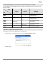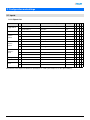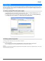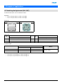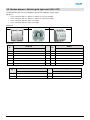
1
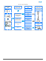
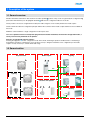
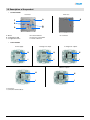
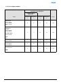
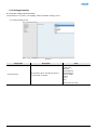
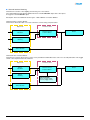
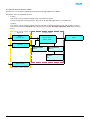
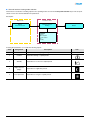
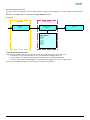
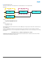
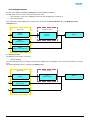
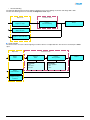
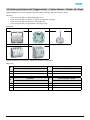
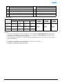
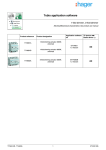
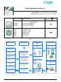
Tebis application software
Input products / ON / OFF output / RF dimmer
Electrical / Mechanical characteristics: see product user manual
TP device
RF devices
Product reference Product designation
WYC81xQ
WYC82xQ
WYC84xQ
Control module
1-fold push button lighting RF
2-fold push button lighting RF
4-fold push button lighting RF
WUC35
WUC21
WUC22
WUD86
WUD87
WUD88
WUC18
Power module
1 changeover output
1 changeover output
2 changeover outputs
1 dimmer output
1 dimmer output
2 dimmer outputs
Power supply
Inputs
RF push button
Media coupler
Output modules
KNX
Products KNX
RF devices
Loads connected
Shutters and blinds
control
Lighting control
Gateway between the
RF products and the TP
products in a KNX
installation
Dimming control
TP products
Heating control
Configuration and
parameter setting of
radio products by ETS
Visualisation
system
Priority
Transmission of radio
controls
Scene
Status indication
WYC81xQ / WYC82xQ / WYC84xQ
Diagnosis
1
6T 8011-02a
ON / OFF output and Dimming
Input modules
KNX
Output modules
KNX
Media coupler
ON / OFF output
Products KNX
Loads connected
ON / OFF
Timer
Scene
Gateway between the
RF products and the TP
products in a KNX
installation
Priority
Dimming output
ON / OFF
Configuration and
parameter setting of
radio products by ETS
Dimming
Brightness value
Timer
Transmission of radio
controls
Priority
Visualisation
system
Scene
Status indication
Diagnosis
Brightness value
indication
WYC81xQ / WYC82xQ / WYC84xQ
2
6T 8011-02a
Summary
1. Description of the system.................................................................................................................................................. 4
1.1 General overview......................................................................................................................................................... 4
1.2 General outline ............................................................................................................................................................ 4
1.3 Description of the product............................................................................................................................................ 5
1.4 Compatibility between the control module and the power module .............................................................................. 6
1.5 Choice of application program in ETS ......................................................................................................................... 6
1.6 Function Description.................................................................................................................................................... 7
1.6.1 Inputs .................................................................................................................................................................... 7
1.6.2 ON / OFF output.................................................................................................................................................... 7
1.6.3 Dimming output ..................................................................................................................................................... 8
1.7 Hardware and software required for configuration ...................................................................................................... 8
2. Configuration and settings ................................................................................................................................................ 9
2.1 Inputs........................................................................................................................................................................... 9
2.1.1 Objects List ........................................................................................................................................................... 9
2.1.2 List of object numbers ......................................................................................................................................... 10
2.1.3 Setting parameters.............................................................................................................................................. 11
2.2 ON / OFF output ........................................................................................................................................................ 18
2.2.1 Objects List ......................................................................................................................................................... 18
2.2.2 Setting parameters.............................................................................................................................................. 19
2.3 Dimming output ......................................................................................................................................................... 22
2.3.1 Objects List ......................................................................................................................................................... 22
2.3.2 Setting parameters.............................................................................................................................................. 23
2.4 Configuration with media coupler (ETS version > 3.0f) ............................................................................................. 27
3. Factory reset ................................................................................................................................................................... 31
3.1 Factory reset by ETS via the media coupler.............................................................................................................. 31
3.2 Factory reset on the product...................................................................................................................................... 31
4. Examples of applications ................................................................................................................................................ 32
4.1 Switching the light on/off (ON / OFF)......................................................................................................................... 32
4.2 2-button dimmer + Switching the light on/off (ON / OFF) .......................................................................................... 33
4.3 Switching the light on/off (Toggle switch) + 1-button dimmer + Shutter, Up / Down ................................................. 35
5. Main characteristics ........................................................................................................................................................ 37
WYC81xQ / WYC82xQ / WYC84xQ
3
6T 8011-02a
1. Description of the system
1.1 General overview
All radio transmitters referred to in this document are radio quicklink products. They can be recognised by the configuration cfg
push button with which they are all equipped. Quicklink indicates the configuration without tools mode.
These products can also be configured in E mode by the USB configurer or in S mode by ETS via the media coupler.
This document describes the configuration principle with the ETS software via the media coupler and the functions available in
this mode.
Within the same installation, a single configuration mode may be used.
To re-use a product which has already been programmed in another installation, whatever the configuration mode, a
factory reset must be performed on the product.
Specifics for quicklink radio transmitters:
Pressing the cfg button acrivates configuration mode. In this mode, the dialogue product is bi-directional. For numbering or
programming operations, it will therefore no longer be necessary to bring the transmitters to be configured up to the media
coupler. It is only necessary to remain within radio range.
1.2 General outline
RF push button
Media coupler
Lighting
KNX
Lighting
Shutters / blinds
Receiver / RF repeater
Heating
WYC81xQ / WYC82xQ / WYC84xQ
4
6T 8011-02a
1.3 Description of the product
•
Control module
Front face
Rear face
B
C
D
A: Button
B: Configuration LED
C: Configuration button
•
G
A
F
E
D: Function button 1
E: Function 1 and 2 LED
F: Function button 2
G: Connector
Power module
Power supply
1 changeover output
2 changeover outputs
H
H
H
I
I
I
1 dimmer output
2 dimmer outputs
H
H
I
I
H: Connector
I: Connection terminal block
WYC81xQ / WYC82xQ / WYC84xQ
5
6T 8011-02a
1.4 Compatibility between the control module and the power module
The control modules are not all compatible with all the power modules. The table below shows the possible interconnections
between the modules:
Control
module
WYC81xQ
WYC82xQ
WYC84xQ
WUC35
WUC21
1-fold push button lighting
RF
1 changeover output
X
4-fold push button lighting RF
1 changeover output
WUC22
X
2-fold push button lighting
RF
2 changeover outputs
4-fold push button lighting RF
2 changeover outputs
WUD86
WUD87
1-fold push button lighting
RF
1 dimmer output
X
4-fold push button lighting RF
1 dimmer output
WUD88
X
2-fold push button lighting
RF
2 dimmer outputs
4-fold push button lighting RF
2 dimmer outputs
WUC18
1-fold push button lighting
RF
2-fold push button lighting
RF
4-fold push button lighting RF
Power
module
1.5 Choice of application program in ETS
Program selection is compulsory according to the type of combination used.
•
Right click on the product in the ETS tree structure, then select Change the application program…,
•
Select the product.
WYC81xQ / WYC82xQ / WYC84xQ
6
6T 8011-02a
1.6 Function Description
1.6.1 Inputs
The radio transmitter application software enables each input to be configured individually. The push buttons are used to control
lighting, shutters and blinds, heating, scenes.
The main functions are the following:
■ Emission of commands
The inputs allow commands for lighting, shutters and blinds, heating settings and scenes to be transmitted.
Emission of commands:
• Lighting control
• Toggle switch, ON, OFF, ON / OFF, Timer
• 1 button or 2 button dimmer
• Shutters / Blinds control
• Up, Down, Stop, Slat angle
• 1 button or 2 button control
• Set point selection (Heating)
• Comfort, Night set-point, Frost protection, Auto, Standby
■ Scene
The Scene function sends group controls to different kinds of outputs to create ambiences or scenarios.
Example of scene 1: Leaving the house (centralised lighting control OFF, shutters on south side 3 / 4 closed, the other shutters
open, heating switched over to Reduced mode).
1.6.2 ON / OFF output
The application software allows you to configure individually the outputs.
The main functions are the following:
■ ON / OFF
The ON / OFF function is used to switch a lighting circuit ON or OFF. The command may come from switches, pushbuttons or
automatic controls.
■ Status indication
The Status indication function displays the status of the output contact. It allows a Toggle function to be created by sending the
status indication to each push button of the group.
■ Timer
The Timer function is used to switch a lighting circuit ON or OFF for an adjustable time. Depending on the operation mode
selected, the output may be delayed for ON or OFF switching. The Timer function can be interrupted via a long key press before
the time delay expires.
■ Priority
The Priority function allows overriding an output to a definite status, ON or OFF. This command has the highest priority. No other
command is taken into account if a priority is active. Only a priority end command re-enables the other commands.
Application: maintaining lighting ON for safety reasons.
■ Scene
The Scene function groups a set of outputs. These outputs can be set to an adjustable predefined status. Pressing a push button
activates a scene. Each output can be integrated in 8 different scenes.
WYC81xQ / WYC82xQ / WYC84xQ
7
6T 8011-02a
1.6.3 Dimming output
The software applications are used to configure the output for the Dimming applications.
The main functions are the following:
■ ON / OFF
The ON / OFF function is used to switch the output ON or OFF.
ON: switching on at the level of lighting active the last time the lighting was switched on.
OFF: switching OFF.
The control can come from push buttons.
■ Status indication
The Status indication function displays the status of the output contact. It allows a Toggle function to be created by sending the
status indication to each push button of the group.
■ Relative or absolute dimming (Brightness value)
The relative dimming allows increasing or decreasing the lighting level as long as a push button is pressed down. The absolute
dimming allows defining in % the lighting level to reach by means of the Lighting level object.
■ Timer
The Timer function is used to switch a lighting circuit ON or OFF for an adjustable time. Depending on the operation mode
selected, the output may be delayed for ON or OFF switching. The Timer function can be interrupted via a long key press before
the time delay expires.
■ Priority
The Priority function allows overriding an output to an adjustable lighting level. This command has the highest priority. No other
command is taken into account if a priority is active. Only a priority end command re-enables the other commands.
Application: maintaining lighting ON for safety reasons.
■ Scene
The Scene function groups a set of outputs. These outputs can be set to an adjustable predefined status. Pressing a push button
activates a scene.
1.7 Hardware and software required for configuration
•
•
•
Windows PC with the ETS software,
(Version 3.0f or higher or 4.0.7 or higher. Download and install the update if necessary.)
Media coupler. The software version must meet the following characteristics:
• Firmware: > 1.2.5
• Plug-in: > 1.0.11
(Check that you have administrator rights under Windows. If not you will not be able to install the media coupler plug-in.)
Programming interface.
WYC81xQ / WYC82xQ / WYC84xQ
8
6T 8011-02a
2. Configuration and settings
2.1 Inputs
2.1.1 Objects List
Parameters
N°
Name
Function of the object
Length
C
R
W T
0
Push button 1
Status indication
1 bit
C
R
W -
1
Push button 1
ON / OFF
1 bit
C
R
-
T
1
Push button 1
ON / OFF
1 bit
C
R
-
T
0
Push button 1
Status indication
1 bit
C
R
W -
1
Push button 1
ON / OFF
1 bit
C
R
-
T
4
Push button 1
Dimming
4 bit
C
R
-
T
0
Push button 1
Status indication
1 bit
C
R
W -
1
Push button 1
ON / OFF
1 bit
C
R
-
T
4
Push button 1
Dimming
4 bit
C
R
-
T
0
Push button 1
Status indication
1 bit
C
R
W -
1
Push button 1
Slat angle / Stop
1 bit
C
R
-
T
2
Push button 1
Up / Down
1 bit
C
R
-
T
Heating
5
Push button 1
Set point selection
1 byte
C
R
-
T
Scene
5
Push button 1
Scene
1 byte
C
R
-
T
0
Push button 1
Status indication
1 bit
C
R
W -
1
Push button 1
Timer
1 bit
C
R
-
Toggle switch
ON / OFF
1-button
dimmer
2-button
dimmer
Shutters /
blinds
Timer
T
The functions of the objects are identical for push buttons 2, 3 and 4 (See chapter 2.2 for the object numbers).
WYC81xQ / WYC82xQ / WYC84xQ
9
6T 8011-02a
2.1.2 List of object numbers
2-fold push button lighting RF
4-fold push button lighting RF
1-fold push button
lighting RF
Number
Push button
1
Number
Push button
2
Number
Push button
3
Number
Push button
4
Length
0
6
12
18
1 bit
1
7
13
19
1 bit
Up / Down:
Shutters / blinds
2
8
14
20
1 bit
Dimming:
1-button dimmer
2-button dimmer
4
10
16
22
4 bit
5
11
17
23
1 byte
Object
Status indication:
Toggle switch
1-button dimmer
2-button dimmer
Shutters / blinds
Timer
ON / OFF:
Toggle switch
ON / OFF
1-button dimmer
2-button dimmer
Slat angle / Stop:
Shutters / blinds
Timer:
Timer
Heating:
Set point selection
Scene:
Scene
WYC81xQ / WYC82xQ / WYC84xQ
10
6T 8011-02a
2.1.3 Setting parameters
■ Parameter setting: Channel function
The push buttons are used to control lighting, shutters and blinds, heating, scenes.
➜ Parameter Setting screen
Screen 1
Designation
Channel function
Description
This parameter allows selecting the function
associated with each input.
Value
Not used
Toggle switch
ON / OFF
1-button dimmer
2-button dimmer
Shutters / blinds
Heating
Scene
Timer
Default value: Not used
WYC81xQ / WYC82xQ / WYC84xQ
11
6T 8011-02a
■ Channel function: Toggle switch
This function is used to switch the lighting circuit or any other load ON or OFF. Each new key-press modifies the output status.
Description: After pressing the connected pushbutton, depending on the Status indication object, an ON or OFF command will
be sent to the bus via the ON / OFF object.
Object ETS
Parameters ETS
Object
ON / OFF
Channel function
Toggle switch
Output
Object
Status indication
■ Channel function: ON / OFF
This function is used to switch the lighting circuit or any other load ON or OFF. The ON or OFF command will be transmitted to
the bus via the ON / OFF object. The command to be sent (ON or OFF) can be defined in the parameters.
Description:
Object ETS
Parameters ETS
Object
ON / OFF
Channel function
ON / OFF
Output
Type of function
OFF
ON
ON / OFF
•
•
•
ON: Emission of the ON control when the input push button is pressed,
OFF: Emission of the OFF control when the input push button is pressed,
ON / OFF: Emission of the ON control when the input push button is pressed and emission of the OFF control when the
input push button is released.
WYC81xQ / WYC82xQ / WYC84xQ
12
6T 8011-02a
■ Channel function: Dimming
This function is used to control lighting circuits using one or two buttons.
The 1 button dimmer and 2 buttons dimmer functions send the ON / OFF object after a short press.
A long press send the Dimmer object.
Description: There are 2 different function types: 1-button dimmer or 2-button dimmer.
Channel function: 1-button dimmer
This function allows ON / OFF or Increase / Decrease controls using one push button.
Object ETS
Object
ON / OFF
Parameters ETS
Channel function
1-button dimmer
Output
Object
Dimming
Object
Status indication
Channel function: 2-button dimmer
This function is used for the Increase control on one push button and the Decrease control on a second push button. The Toggle
switch control is performed on the 2 buttons.
Object ETS
Object
ON / OFF
Parameters ETS
Channel function
2-button dimmer
Output
Object
Dimming
Type of function
Increase (Toggle switch)
Decrease (Toggle switch)
Object
Status indication
WYC81xQ / WYC82xQ / WYC84xQ
13
6T 8011-02a
■ Channel function: Shutters / blinds
This function controls shutters and blinds (Up, Down and slat angle adjustment for blinds).
Description: There are 2 different functions:
• 1-button,
This function controls shutters or blinds using one push buttons (Input).
Function change after each press (Down, Stop, Up, Stop). Slat angle adjustment is not possible here.
•
2-buttons.
This function controls shutters or blinds using two push buttons (Input). One button for Up and one button for down.
The function transmit the Up / Down object (long key press) and the Slat angle adjustment / Stop object (short key
press).
Object ETS
Parameters ETS
Object
Slat angle / Stop
Channel function
Shutters / blinds
Output
Object
Up / Down
Type of function
Type of function
1-button
2-buttons
Function
Up
Down
Object
Status indication
WYC81xQ / WYC82xQ / WYC84xQ
14
6T 8011-02a
■ Channel function: Heating mode selection
This function is used select a heating setpoint. The operating modes are sent via the Set point selection object. The set point
selection to be sent must be defined in the parameters.
Description:
Object ETS
Parameters ETS
Object
Set point selection
Channel function
Heating
Output
Function
Comfort
Night set-point
Frost protection
Auto
Standby
Pressing the push button once sends the following objects:
Value
Designation
0
Auto
Temperature defined by programming.
1
Comfort
Temperature during occupied periods.
2
Standby
Temperature for a short unoccupied period.
3
Night set-point
(Night)
Temperature for night-time periods.
4
Frost protection
Temperature for long unoccupied periods.
WYC81xQ / WYC82xQ / WYC84xQ
Description
15
Icon
6T 8011-02a
■ Channel function: Scene
The Scene function sends group controls to different kinds of outputs to create ambiences or scenarios (Panic switch, Television,
etc.).
The value of the Scene object is defined by the Scene number parameter.
Description:
Object ETS
Parameters ETS
Object
Scene
Channel function
Scene
Output
Scene number
Scene 1
Scene 2
Scene 3
Scene 4
Scene 5
Scene 6
Scene 7
Scene 8
Learning and storing in the room
This procedure modifies and stores a scene by local action on the push buttons located in the room:
• Activate the scene by pressing briefly on the room push button that triggers the scene,
• Set the outputs to the desired status using the push buttons that control them individually,
• Store the output statuses by pressing the room push button that triggers the scene for longer than 5 s.
Storage is indicated by the inversion of the status of the outputs concerned for 3s.
WYC81xQ / WYC82xQ / WYC84xQ
16
6T 8011-02a
■ Channel function: Timer
This function operates like a staircase light function. The timer duration is set on the output module.
Description:
Object ETS
Parameters ETS
Object
Timer
Channel function
Timer
Output
Object
Status indication
Feature:
• short key press (rising edge): Timer start,
• long key press (falling edge): Timer end.
Remark:
• short key-press: < 0.4 s
• long key-press: >= 0.4 s
A short key-press sends an ON command to the bus via the Timer object. A long key-press sends an OFF command to the bus
via the Timer object.
The time is retriggered in the output by a recurrent short key press. Successive presses on the control button for the timer
increase the timer's duration. The effective length will then be multiplied by the number of presses made during the 10 s following
the first press.
ON changeover time = (1 + Number of repeated presses) * Set time
The delay time starts after the last key-press. An ON command received after the 10 s restarts the set turn-on time. An OFF
command switches immediately the output to OFF.
WYC81xQ / WYC82xQ / WYC84xQ
17
6T 8011-02a
2.2 ON / OFF output
2.2.1 Objects List
•
1 changeover output
N°
Name
Function of the object
Length
C
R
W
T
12
Output
ON / OFF
1 bit
C
R
W
-
13
Output
Timer
1 bit
C
R
W
-
14
Output
Priority
2 bit
C
R
W
-
15
Output
Scene
1 byte
C
R
W
-
16
Output
Status indication
1 bit
C
R
-
T
C
R
W
T
•
2 changeover outputs
N°
Name
Function of the object
Length
24
Output 1
ON / OFF
1 bit
C
R
W
-
25
Output 1
Timer
1 bit
C
R
W
-
26
Output 1
Priority
2 bit
C
R
W
-
27
Output 1
Scene
1 byte
C
R
W
-
28
Output 1
Status indication
1 bit
C
R
-
T
29
Output 2
ON / OFF
1 bit
C
R
W
-
30
Output 2
Timer
1 bit
C
R
W
-
31
Output 2
Priority
2 bit
C
R
W
-
32
Output 2
Scene
1 byte
C
R
W
-
33
Output 2
Status indication
1 bit
C
R
-
T
WYC81xQ / WYC82xQ / WYC84xQ
18
6T 8011-02a
2.2.2 Setting parameters
■ Function ON / OFF, Status indication
The ON / OFF function is used to switch the output ON or OFF. The status of the output depends on the activation of other
functions and of the associated parameters: priority, timer or scene.
The status of the output is indicated on the bus by the Status indication object.
Object ETS
Parameters ETS
Object
ON / OFF
Function
ON / OFF
Output
Object
Status indication
■ Timer function
The Timer function is used to switch a lighting circuit ON or OFF for an adjustable time. The function is started by the Timer
object.
Object ETS
Object
Timer
Parameters ETS
Function
Timer
Function
Timer operation
Parameter:
Parameter:
Timer:
- Not active
- Duration
Timer operation:
- ON
- OFF
Output
Object
Status indication
WYC81xQ / WYC82xQ / WYC84xQ
19
6T 8011-02a
➜ Parameters
Parameter
Description
Value
Not active, [1 s - 24 h]*
Timer
This parameter defines the length of the delay time.
Default value: 3 min
This parameter defines whether the delay time triggers an
ON or an OFF status.
Timer operation
ON, OFF
Default value: ON
* Setting range [1 s - 24 h]
1 s, 2 s, 3 s, 5 s, 10 s, 15 s, 20 s, 30 s, 45 s, 1 min, 1 min 15 s, 1 min 30 s, 2 min, 2 min 30 s, 3 min, 5 min, 15 min, 20 min, 30 min,
1 h, 2 h, 3 h, 5 h, 12 h, 24 h.
■ Priority function
The Priority function allows the outputs to be forced and maintained at a definite ON or OFF status imposed by the input. This
function is started by the Priority object.
Priority is the function with the highest priority. Only a cancellation command for the priority can end the priority and authorise
other commands to be followed again.
Object ETS
Parameters ETS
Object
Priority
Priority function
Output
Parameter:
Status after priority
- Maintain
- Inversion
Object
Status indication
➜ Description of the Priority object
Value
Output behaviour
00
Priority end
01
Priority end
10
Priority ON
11
Priority OFF
WYC81xQ / WYC82xQ / WYC84xQ
20
6T 8011-02a
➜ Parameters
Parameter
Description
Value
This parameter defines the level of lighting
applied at the end of the priority.
Status after priority
Maintain, Inversion
- Maintain: The output is maintained in the
status which was active before the priority,
- Inversion: Inversion of the output's status with
regards to the status active during Priority (ON
to OFF and OFF to ON).
Default value: Maintain
■ Scene function
A scene is used to control a group of outputs. Each of the outputs in the group will be set to a status pre-defined for the scene.
A scene has been initiated by the object Scene.
The group of outputs is created in advance by establishing the link between the outputs that are to be part of the scene and the
push button which initiates the scene. Each output can be integrated in 8 different scenes.
Object ETS
Parameters ETS
Object
Scene
Function
Scene
Output
Object
Status indication
➜ Description of the Scene object (1 byte)
7
6
Learn
x
5
4
3
2
1
0
Scene number
Learning and storing in the room
This procedure modifies and stores a scene by local action on the push buttons located in the room:
• Activate the scene by pressing briefly on the room push button that triggers the scene,
• Set the outputs to the desired status using the push buttons that control them individually,
• Store the output statuses by pressing the room push button that triggers the scene for longer than 5 s.
Storage is indicated by the inversion of the status of the outputs concerned for 3s.
WYC81xQ / WYC82xQ / WYC84xQ
21
6T 8011-02a
2.3 Dimming output
2.3.1 Objects List
•
N°*
1 dimmer output
N°**
Name
Function of the object
Length
C
R
W
T
12
24
Output
ON / OFF
1 bit
C
R
W
-
13
25
Output
Dimming
4 bit
C
R
W
-
14
26
Output
Brightness value
1 byte
C
R
W
-
15
27
Output
Timer
1 bit
C
C
W
-
16
28
Output
Priority
2 bit
C
R
W
-
17
29
Output
Scene
1 byte
C
C
W
-
18
30
Output
Status indication
1 bit
C
C
-
T
19
31
Output
Brightness value indication
1 byte
C
C
-
T
C
R
W
T
* With 1-fold push button lighting RF module.
** With 4-fold push button lighting RF module.
•
N°
2 dimmer outputs
Name
Function of the object
Length
24
Output 1
ON / OFF
1 bit
C
R
W
-
25
Output 1
Dimming
4 bit
C
R
W
-
26
Output 1
Brightness value
1 byte
C
R
W
-
27
Output 1
Timer
1 bit
C
C
W
-
28
Output 1
Priority
2 bit
C
R
W
-
29
Output 1
Scene
1 byte
C
C
W
-
30
Output 1
Status indication
1 bit
C
C
-
T
31
Output 1
Brightness value indication
1 byte
C
C
-
T
32
Output 2
ON / OFF
1 bit
C
R
W
-
33
Output 2
Dimming
4 bit
C
R
W
-
34
Output 2
Brightness value
1 byte
C
R
W
-
35
Output 2
Timer
1 bit
C
C
W
-
36
Output 2
Priority
2 bit
C
R
W
-
37
Output 2
Scene
1 byte
C
C
W
-
38
Output 2
Status indication
1 bit
C
C
-
T
39
Output 2
Brightness value indication
1 byte
C
C
-
T
WYC81xQ / WYC82xQ / WYC84xQ
22
6T 8011-02a
2.3.2 Setting parameters
■ ON / OFF, Status indication and Brightness value indication functions
The ON / OFF function is used to switch the output ON or OFF:
• ON: switching on at the level of lighting active the last time the lighting was switched on.
• OFF: switching OFF.
The output status and the lighting level are indicated on the bus by the Status indication object and Brightness value
indication object.
Object ETS
Object
ON / OFF
Parameters ETS
Function
ON / OFF
Output
Object
Status indication
Object
Brightness value indication
■ Dimming function
The dimming can be relative or absolute.
• Relative dimming
The relative dimming allows increasing or decreasing the lighting level of the lighting circuit as long as a push button is pressed
down.
The relative dimming function is started by the Dimming object.
Object ETS
Object
Dimming
Parameters ETS
Function
Relative dimming
Output
Object
Status indication
Object
Brightness value indication
WYC81xQ / WYC82xQ / WYC84xQ
23
6T 8011-02a
• Absolute dimming
The Absolute dimming function allows applying a brightness level to the lighting circuit when switching it ON or OFF.
The absolute dimming function is started by the Brightness value object.
Object ETS
Parameters ETS
Object
Brightness value
Function
Absolute dimming
Output
Object
Status indication
Object
Brightness value indication
■ Timer function
The Timer function is used to switch a lighting circuit ON or OFF for an adjustable time. The function is started by the Timer
object.
Object ETS
Object
Timer
Parameters ETS
Function
Timer
Function
Timer operation
Parameter:
Parameter:
Timer:
- Not active
- Duration
Timer operation:
- ON
- OFF
Output
Object
Status indication
Object
Brightness value
indication
WYC81xQ / WYC82xQ / WYC84xQ
24
6T 8011-02a
➜ Parameters
Parameter
Description
Value
This parameter defines the length of the delay
time.
Timer
This parameter defines whether the delay time
triggers an ON or an OFF status.
Timer operation
Not active, [1 s - 24 h]*
Default value: 3 min
ON, OFF
Default value: ON
* Setting range [1 s - 24 h]
1 s, 2 s, 3 s, 5 s, 10 s, 15 s, 20 s, 30 s, 45 s, 1 min, 1 min 15 s, 1 min 30 s, 2 min, 2 min 30 s, 3 min, 5 min, 15 min, 20 min, 30 min,
1 h, 2 h, 3 h, 5 h, 12 h, 24 h.
■ Priority function
The Priority function allows the outputs to be forced and maintained at a definite ON or OFF status imposed by the input. This
function is started by the Priority object.
Priority is the function with the highest priority. Only a cancellation command for the priority can end the priority and authorise
other commands to be followed again.
Object ETS
Parameters ETS
Object
Priority
Priority function
Output
Parameter:
Status after priority
- Maintain
- Inversion
Object
Status indication
Object
Brightness value indication
➜ Description of the Priority object
Value
Output behaviour
00
Priority end
01
Priority end
10
Priority ON
11
Priority OFF
WYC81xQ / WYC82xQ / WYC84xQ
25
6T 8011-02a
➜ Parameters
Parameter
Description
Value
This parameter defines the level of lighting
applied at the end of the priority.
Status after priority
Maintain, Inversion
- Maintain: The output is maintained in the
status which was active before the priority,
- Inversion: Inversion of the output's status with
regards to the status active during Priority (ON
to OFF and OFF to ON).
Default value: Maintain
■ Scene function
A scene is used to control a group of outputs. Each of the outputs in the group will be set to a status pre-defined for the scene.
A scene has been initiated by the object Scene.
The group of outputs is created in advance by establishing the link between the outputs that are to be part of the scene and the
push button which initiates the scene. Each output can be integrated in 8 different scenes.
Object ETS
Parameters ETS
Object
Scene
Function
Scene
Output
Object
Status indication
Object
Brightness value indication
➜ Description of the Scene object (1 byte)
7
6
Learn
x
5
4
3
2
1
0
Scene number
Learning and storing in the room
This procedure modifies and stores a scene by local action on the push buttons located in the room:
• Activate the scene by pressing briefly on the room push button that triggers the scene,
• Set the outputs to the desired status using the push buttons that control them individually,
• Store the output statuses by pressing the room push button that triggers the scene for longer than 5 s.
Storage is indicated by the inversion of the status of the outputs concerned for 3s.
WYC81xQ / WYC82xQ / WYC84xQ
26
6T 8011-02a
2.4 Configuration with media coupler (ETS version > 3.0f)
■ Configuration principle
The TR131 media coupler enables confuguration by ETS of RF devices for a KNX radio installation or a mixed KNX installation
including RF devices and wired buses. For normal operation, the radio transmitters operate in a one-direction mode.
Configuration takes place in bi-directional mode.
■ Implementation recommendations
1. The Media coupler must remain in place after configuration. It sends the commands between the radio products and the
wired products in auto mode.
2. The coupler must be at the head of the line: x.y.0 type physical address.
3. The coupler must be in a different line than the USB / series / IP interface.
4. Use of old generation media couplers (TR130A / B) is not authorised in an installation containing a new media coupler
(TR131A / B).
5. Separate the radio and TP lines:
• The radio line must not contain TP products: the views of the line in ETS and in the plug-in would contain
inconsistencies.
• The TP lines must not contain radio products: it would be impossible to configure these radio products.
6. Only use the plug-in to program the physical addresses and download the products. As ETS cannot program radio
products, it is not possible to use the usual configuration menus.
7. The product copy function must not be used in ETS for radio products. It causes inconsistencies in the projects leading to
plug-in malfunctions.
8. Copying projects which already contain a configured media coupler leads to plug-in malfunctions.
9. The use of the "default" button in the ETS parameter setting window is not recommended. This results in:
➜ The loss of the parameters of a product which has already been configured.
➜ Desynchronisation between the plug-in data and the radio products which have already been configured.
10. During the physical addressing, the download or the factory reset procedures of unidirectional radio products, several
attempts may be needed for a successful completion of the procedure.
11. Changing the line of a media coupler which is already configured leads to plug-in malfunctions.
12. Do not use ETS Software function Unload / Unload application.
WYC81xQ / WYC82xQ / WYC84xQ
27
6T 8011-02a
■ Installation procedure
• Create a line reserved for RF devices in your ETS plan,
• First insert the media coupler into this line, then insert the other RF devices into this line,
• Perform the programming, parameter settings and group addressing for all the RF products except for the media coupler,
• Download the physical address of the media coupler. This must be of the type 1.1.0. (always end with a zero),
• Install the media coupler plug-in: Right-click on the product in the ETS tree structure, then select edit the parameters.
Windows Administrator rights are necessary to install the plug in.
WYC81xQ / WYC82xQ / WYC84xQ
28
6T 8011-02a
■ Physical addressing of the radio transmitters
• Click on the button Physical addressing to display the physical addressing screen for the plug in,
• Select the device to be addressed, then click on the field Addressing in the menu line at the upper left of the window,
• Click on Product search, if the product is not found by the search, perform a factory reset on the product outside the
installation,
• Select the device to be addressed and click on Attribute address. The physical addressing of the product is performed.
The product is now part of the installation,
• After downloading the physical address, the
symbol appears in front of the product,
• Repeat this operation for the other radio transmitters.
WYC81xQ / WYC82xQ / WYC84xQ
29
6T 8011-02a
■ Downloading the program and the parameters
This operation is performed using the plug-in. There are 2 ways of accessing the Download view:
•
From the media coupler
• Right-click on the product in the ETS tree structure, then select edit the parameters,
• Click on Download and follow the instructions on the screen.
•
From the RF product to be downloaded
• Right click on the product in the ETS tree structure, then select Download RF product… and follow the instructions
on the screen.
The right-hand window allows you to select the parameters and / or links to be downloaded for each product.
Finalise the download by selecting the type of download in the upper bar:
• Selected to download the selected parameters and links,
• All parameters to download all the parameters of all the products displayed,
• All links to download all the links for all the products displayed,
• All to download all the parameters and all the links of all the products displayed.
To test the functions and the KNX radio communication, return to normal use mode and wait 15 s before pressing a control button
on a transmitter.
Caution: The media coupler plug-in must be deactivated during the functional tests.
NB: For more information, refer to the description for the TR131 application software.
WYC81xQ / WYC82xQ / WYC84xQ
30
6T 8011-02a
3. Factory reset
This function enables the device to be returned to its initial configuration (configuration when it came out of the factory). After a
device reset, the device can be re-used in a new installation. A factory reset can be performed either directly on the product or by
the media coupler plug-in. This last solution is recommended if the product is part of an installation configured by ETS, thus the
device is erased from the project.
3.1 Factory reset by ETS via the media coupler
•
•
For a product which is part of the installation (known by the media coupler): In the Physical addressing menu, select
Factory reset and then follow the instructions which appear on the screen,
For a product which is not part of the installation (unknown by the media coupler): In the menu Physical addressing,
select RESET device out of installation, then Unidirectional device with Addr. button.
3.2 Factory reset on the product
It is always possible to perform the factory reset directly on the device.
Factory reset on the product:
• Do a long key press (> 10 seconds) on the cfg push button, release the button when the cfg LED blinks,
• Wait for the cfg LED to switch off, indicating that the factory reset has been completed.
Remark:
To re-use a product which has already been programmed in another installation, whatever the configuration mode, a factory reset
must be performed on the product.
WYC81xQ / WYC82xQ / WYC84xQ
31
6T 8011-02a
4. Examples of applications
4.1 Switching the light on/off (ON / OFF)
The WYC81xQ module controls the WUC35 module.
Operation:
• Press on the push button 1: Switch on the light,
• Press on the push button 2: Switch off the light.
Equipment:
1x WYC81xQ
1x WUC35
Object KNX
WYC81xQ
WUC35
N°
N°
Object name
Object name
1
Push button 1 - ON / OFF
➜
12
Output - ON / OFF
7
Push button 2 - ON / OFF
➜
12
Output - ON / OFF
Parameters KNX
WYC81xQ
WUC35
Push button 1
Push button 2
Channel function
ON / OFF
ON / OFF
Function
ON
OFF
Default settings
Comment:
• A short press on push button 1 switches the light on,
• A short press on push button 2 switches the light off.
WYC81xQ / WYC82xQ / WYC84xQ
32
6T 8011-02a
4.2 2-button dimmer + Switching the light on/off (ON / OFF)
The WYC82xQ module controls the WUD88 module and the 6 ON/OFF outputs module.
Operation:
• Press on the push button 1 : Switch on / Switch off + Increase the light,
• Press on the push button 2 : Switch on / Switch off + Decrease the light,
• Press on the push button 3: Switch on the light,
• Press on the push button 4: Switch off the light.
Equipment:
1xWYC82xQ
1x WUD88
1 6 ON / OFF outputs module
Object KNX
WYC82xQ
WUD88
N°
N°
Object name
Object name
0
Push button 1 - Status indication
➜
30
Output 1 - Status indication
1
Push button 1 - ON / OFF
➜
24
Output 1 - ON / OFF
4
Push button 1 - Dimming
➜
25
Output 1 - Dimming
6
Push button 2 - Status indication
➜
30
Output 1 - Status indication
7
Push button 2 - ON / OFF
➜
24
Output 1 - ON / OFF
10
Push button 2 - Dimming
➜
25
Output 1 - Dimming
WYC82xQ
6 ON/OFF outputs module
Object name
Object name
N°
13
Push button 3 - ON / OFF
➜
Output - ON / OFF
19
Push button 4 - ON / OFF
➜
Output - ON / OFF
WYC81xQ / WYC82xQ / WYC84xQ
33
6T 8011-02a
Parameters KNX
6 ON/OFF outputs
module
WYC82xQ
WUD88
Push button 1
Push button
2
Channel
function
2-button
dimmer
2-button
dimmer
Function
Increase
(Toggle
switch)
Decrease
(Toggle
switch)
Push button Push button
3
4
ON / OFF
ON / OFF
Default settings
ON
Default settings
OFF
Comment:
• A short press on push button 1 switches the light on or off according to the Status indication object (ON or OFF),
• A short press on push button 2 switches the light on or off according to the Status indication object (ON or OFF),
• A long press on push button 1 increases the light,
• A long press on push button 2 decreases the light,
• A short press on push button 3 switches the light on,
• A short press on push button 4 switches the light off.
WYC81xQ / WYC82xQ / WYC84xQ
34
6T 8011-02a
4.3 Switching the light on/off (Toggle switch) + 1-button dimmer + Shutter, Up / Down
Module WYC84xQ controls the 1 ON/OFF output RF module, 3 dimming outputs and 4 shutter outputs.
Operation:
• Press on the push button 1 : Switching the light on/off,
• Press on the push button 2 : Switch on / Switch off + Dimming of the light,
• Press on the push button 3: Shutter up + Slat angle / Stop,
• Press on the push button 4: Shutter Down + Slat angle / Stop.
Equipment:
1x WYC84xQ
1x WUC18
1 1 ON/OFF output RF module
1 3 dimming outputs module
1 4 shutter outputs module
Remark: The WUC18 power module is only used to power the control module.
Object KNX
WYC84xQ
1 ON/OFF output RF module
Object name
Object name
N°
0
Push button 1 - Status indication
➜
Output - Status indication
1
Push button 1 - ON / OFF
➜
Output - ON / OFF
WYC84xQ
3 dimming outputs module
Object name
Object name
N°
6
Push button 2 - Status indication
➜
Output - Status indication
7
Push button 2 - ON / OFF
➜
Output - ON / OFF
10
Push button 2 - Dimming
➜
Output - Dimming
WYC81xQ / WYC82xQ / WYC84xQ
35
6T 8011-02a
WYC84xQ
4 shutter outputs module
Object name
Object name
N°
13
Push button 3 - Slat angle / Stop
➜
Output - Slat angle / Stop
14
Push button 3 - Up / Down
➜
Output - Up / Down
19
Push button 4 - Slat angle / Stop
➜
Output - Slat angle / Stop
20
Push button 4 - Up / Down
➜
Output - Up / Down
Parameters KNX
WYC84xQ
Push button
Push button 1
2
Push button
3
Push button
4
Shutters /
blinds
Shutters /
blinds
Type of
function
2-buttons
2-buttons
Function
Up
Down
Channel
function
Toggle switch
1-button
dimmer
1 ON/OFF
output RF
module
Default
settings
3 dimming
outputs
module
Default
settings
4 shutter
outputs
module
Default
settings
Comment:
• A short press on push button 1 switches the light on or off according to the Status indication object (ON or OFF),
• A short press on push button 2 switches the light on or off according to the Status indication object (ON or OFF),
• A first long press on push button 2 increases the light,
• A second long press on push button 2 decreases the light, (The dimming direction is reversed each time the button is
pushed and held down.)
•
•
•
A short press on push button 3 or 4 stops the shutter or tilts the slats of the blind,
A long press on push button 3 raises the shutters,
A long press on push button 4 lowers the shutters.
WYC81xQ / WYC82xQ / WYC84xQ
36
6T 8011-02a
5. Main characteristics
Product
WYC81xQ
WYC82xQ
WYC84xQ
Max. number of group addresses
80
80
80
Max. number of links
90
90
90
WYC81xQ / WYC82xQ / WYC84xQ
37
6T 8011-02a
WYC81xQ / WYC82xQ / WYC84xQ
38
6T 8011-02a