1
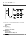
Ethernet Minimodule
User’s
Manual
REV 0.9
,
lu ard ST Sta rve
a
,
e
o
Ev B VR ers b S l
d
n
io 1, A trol We mo
t
a ‘5
n d
ni ri
o
e
r
c
fo cro dd s M the
e
s
d e
i
m mb oar rs, peC E B
e S
PI its ng roll gh r
K pi nt Hi fo
r
y
o
rte tot roc FID ers s
o c
r
Pr mi s, R mm lle
rs or ler gra tro
f ol
n
o
s
pr oco CB
e ntr
l
u o
m icr s, P for
c
e
t
t
m m ds
s
ne Sy T
te ar s
S
l
n
I
,
sy Bo tro
C
d
e PI or ion on b
,
es at roc We
R
c
u
AV pro val mic ed iro E
dd
ic ng PIC be ds m
M ni T, m
r
g S E oa rs,
i
s
, ts
e
B
de VR Ki ng roll
t
h
A ter pi
n
g
i
,
y
o
t
1 r
H
‘5 Sta oto roc ID c
r
e
rs P mi RF m
e
s
l
,
r
er fo ers ram trlv
g n
r
s
ll
Se ule tro pro oco
od con ms icr s,
m
ni net ste T m stem
er Sy , S sy Bo
h
et d In PIC sor on e
, ce ati
ic
e
R
m
o
u
Sp AV opr val IC e
r r
fo ic g E T, P mb
rs s M nin , S
E g
s
r
t
g
R
i
i
in
le
ol des , AV er K typ
B `51 tart roto roS s P mic ,
PC for
s
s ller
er for llers
d
ar tro erw les tro on b S du con ram
c
ro We imo et rog o
n
p
n
ed Mi her m roc
d
d ds et ste ic
ar rs, Sy T m r
o
B olle In , S so
tr ed IC oce ign
P
s
co Spe R, opr De
V cr
h
B Rtion
ig r A Mi
C
a
H f o rs
, Pone asolution
lu
Many ideas
s
e
s
l
v s
m
er ol
m ntr ste g E ard
co Sy nin Bo
Contents
1 INTRODUCTION ....................................................................................................................................... 3
APPLICATIONS .............................................................................................................................................. 4
FEATURES .................................................................................................................................................... 4
CONSTRUCTION OF THE MODULE ............................................................................................... 5
2
BLOCK DIAGRAM .......................................................................................................................................... 5
MODULE PIN-OUT ......................................................................................................................................... 6
ATMEGA128 MICROCONTROLLER ............................................................................................................. 13
ETHERNET CONTROLLER LAN91C111..................................................................................................... 13
MEMORY CONTROLLER .............................................................................................................................. 14
RAM MEMORY ........................................................................................................................................... 19
DATAFLASH MEMORY................................................................................................................................. 19
REAL-TIME CLOCK ...................................................................................................................................... 20
SUPPLY OF POWER .................................................................................................................................... 20
RESET CIRCUIT ........................................................................................................................................ 20
LED DIODES ............................................................................................................................................... 21
CONNECTION OF THE MODULE WITH THE EXTERNAL WORLD ....................................... 22
3
CONNECTION TO THE ETHERNET NETWORK ............................................................................................. 22
USB INTERFACE ........................................................................................................................................ 22
RS-232 INTERFACE ................................................................................................................................... 23
RS-485 INTERFACE ................................................................................................................................... 23
RADIO LINK ................................................................................................................................................. 24
LCD DISPLAY ............................................................................................................................................. 24
EXTERNAL PERIPHERALS ON THE SYSTEM BUS ......................................................................................... 25
PROGRAMMING THE MODULE..................................................................................................... 27
4
ISP CONNECTOR ........................................................................................................................................ 27
JTAG CONNECTOR .................................................................................................................................... 29
5
AN APPLICATION EXAMPLE ......................................................................................................... 30
6
EVALUATION BOARD...................................................................................................................... 31
7
SPECIFICATIONS.............................................................................................................................. 31
8
TECHNICAL ASSISTANCE ............................................................................................................. 32
9
GUARANTEE ...................................................................................................................................... 32
10
ASSEMBLY DRAWINGS.............................................................................................................. 32
11
DIMENSIONS .................................................................................................................................. 34
12
SCHEMATICS ................................................................................................................................. 34
1 Introduction
Thank you very much for having bought our minimodule MMnet104. It was created with the idea
of facilitating the communication of microprocessor systems through the Internet/Ethernet
networks.
The heart of the module is the RISC Atmega128 microcontroller with 128kB of program memory
and 128kB of (external) RAM memory, co-operating with the Ethernet RTL8018AS controller
(100BaseTX). The memory controller built around a programmable CPLD device manages the
address space of the microcontroller, generates address strobe/selection signals used during
extension of the server by external I/O units, and serves the banking of RAM memory. The
minimodule has an 8 MB DataFlash serial memory for storage of WWW pages and of any files
e.g. with measurement data. The memory is connected to a fast SPI bus with 8 Mb/s transmission
speed. The MMnet104 has been equipped with a RTC clock built around the DS1307 device,
connected to the I2C bus. Together with the RTC circuit goes a socket for a lithium battery
providing many guaranteed years of uninterrupted clock operation.
MMnet104 operates under real-time control RTOS allowing to build applications with the use of
pseudo-concurrency in which different tasks are started and executed in the form of separate
threads. This permits an easy construction of applications which require parallel execution of
several tasks, for example servicing the TCP/IP stack and realizing the algorithm of control of an
industrial process. The RTOS system has an extended interface for handling peripheral
equipment, thanks to which the communication with them occurs via drivers registered in the
system. The system has drivers for the Ethernet controller, serial ports, the 1-Wire bus, the DS
1820 thermometer, LCD display RTC clock and DataFlash memory. The kernel of the RTOS
system and the TCP/IP stack together with implemented DHCP, UDP, ICMP, SMTP protocols and
HTTP with simple CGI-s were compiled to libraries.
The system incorporates a series of demonstration applications (WWW server, FTP, Telnet, TCP
client, TCP server, temperature monitoring and control, applications in the RTOS system) which
are basing on completed functions present in the IP stack and RTOS operating system libraries.
Attached libraries permit independent experiments (e.g. creation of web pages using the CGI
technique without penetrating the lower layers of the IP stack and the RTOS operating system).
The MMnet104 is delivered loaded with the WWW Server application and WWW demonstration
pages with examples of using CGI and Flash. The configuration of the server (MAC address, IP,
gateway, change of WWW page) can be effected remotely through serial RS232 or FTP ports.
Sources in C-language and ready libraries are attached to the server; they can be used to realize
one’s own projects. To modify and compile, the free C-compile GCC or C-compiler from
ImageCraft can be put into use.
We wish you nothing but success and a lot of satisfaction in designing and
developing new electronic equipment based on the MMnet104 minimodule.
3
Applications
The MMnet104 minimodule can be used as a design base for electronic circuits co-operating from the
Ethernet/Internet network, covering the following areas of interest:
•
•
•
•
•
•
•
•
•
•
•
Industrial remote controlling and monitoring systems
Telemetry
Intelligent buildings
Alarm systems
Weather stations and environment monitoring
Medical electronics
Heating and air-conditioning systems
Telecommunication
Road traffic monitoring
Remote data logging
Home automation
The MMnet104 minimodule can be also used in didactic workshops of information and electronic schools,
illustrating the aspects of co-operation of electronic circuits from the Ethernet/Internet network, as well as be
used to construct thesis circuits.
Features
•
•
•
•
•
•
•
•
•
•
•
•
•
•
•
•
•
•
•
Fast RISC microcontroller ATmega128 with up to 16 MIPS throughput
Ethernet controller IEEE 802.3 10/100Mb/s
Onboard RJ45 connector with integrated magnetics and LED diodes
Onboard USB interface (device) with USB-B connector
128kB of in circuit programmable FLASH program memory
128KB of RAM memory
4kB of EEPROM memory
(1)
Serial DataFlash memory 32 or 64Mbit (4 or 8MBytes)
Flexible memory controller, allowing suit address space to application requirements
(1)
I2C Real Time Clock and battery socket
Reliable reset circuit
Crystal resonator 14.7456 or 16 MHz
Crystal resonators 32.768 Hz for RTC and MCU internal timer/counter
4 LED diodes indicating: power, LAN activity, DataFlash activity
Fully SMD made on 4-layer PCB
2 x 32 terminals with 0.1" (2.54mm) pitch fitting every prototype board
Available free operating system with TCP/IP stack supporting many protocols
Available evaluation board and sample applications
Small dimensions: 56mm x 59mm
Remarks: 1. Assembled in dependence on the MMnet104 version
4
2 Construction of the module
Block diagram
The block diagram of the MMnet104 minimodule is shown in the drawing:
BUS
memory
controller
PORTE
USB
128kB RAM
ATmega128
LAN91C111
PORTF
EEPROM
PORTB
PORTD
RTC
16MHz
DataFlash 1
DataFlash 2
32kHz
32kHz
Batt
GND
Figure 1 Block diagram of the MMnet104 minimodule.
The minimodule is sold in three basic versions, denoted with letters from A to C, or in accordance with
individual orders.
Module MMnet104- A contains:
• ATmega128 microcontroller
• Ethernet controller LAN91C111
• 128kB RAM
Module MMnet104- B contains:
• ATmega128 microcontroller
• Ethernet controller LAN91C111
• 128kB RAM
• One DataFlash 32Mb (4MB) memory
• Real Time Clock with socket for lithium battery
Module MMnet104- C contains:
• ATmega128 microcontroller
• Ethernet controller LAN91C111
• 128kB RAM
• Two DataFlash memories with 64Mb (8MB) of total capacity
• Real Time Clock with socket for lithium battery
5
Individual orders coding:
MMnet104 – r – b – f – x – e
0 – without RTC
1 - RTC DS1307
0 - without DataFlash memory
1 - 32Mb DataFlash
2 - 2x32Mb DataFlash
0 – without battery socket
1 - with CR2023 battery socket
3.6864
4
6
8
11.059
14.7456
16
0 - without LAN91C111
1 - with LAN91C111
- Crystal 3.6864 MHz
- Crystal 4 MHz
- Crystal 6 MHz
- Crystal 8 MHz
- Crystal 11.059 MHz
- Crystal 14.7456 MHz
- Crystal 16 MHz
Module pin-out
Figure 2 Module pin-out – top view.
6
Function in MMnet104
Interrupt from
LAN91C111 (optionally)
Interrupt from
LAN91C111
USB – TxD
Function in MMnet104
RTC – SDA
DataFlash1 – #CS
DataFlash1/2 – MISO
DataFlash1/2 – SCK
J1
Name
Name
AD7
1
2
AD6
AD5
3
4
AD4
AD3
5
6
AD2
AD1
7
8
AD0
A1
9
10
A0
SEL2
11
12
SEL1
PE7/ INT7
13
14
PE6/ INT6
PE5/ INT5
15
16
PE4/ INT4
PE3/ AC-
17
18
PE2/ AC+
PE1/ PDO/TxD
19
20
PE0/ PDI/RxD
PF7/ ADC7/TDI
21
22
PF6/ ADC6/TDO
PF5/ ADC5/TMS
23
24
PF4/ ADC4/TCK
PF3/ADC3
25
26
PF2/ ADC2
PF1/ ADC1
27
28
PF0/ ADC0
AREF
29
30
AGND
A+5V
31
32
AGND
J2
Name
Name
Function in MMnet104
USB – RxD
Function in MMnet104
+5V
1
2
GND
+3.3V
3
4
GND
Vbat
5
6
GND
NC
7
8
NC
NC
9
10
NC
LEDLINK
11
12
LEDACT
#RESET
13
14
LEDDF
#WR
15
16
#RD
PD7/T2
17
18
PD6/ T1
PD5
19
20
PD4/ IC1
PD3/#INT3/TxD1
21
22
PD2/#INT2/RxD1
PD1/#INT1/SDA
23
24
PD0/#INT0/SCL
RTC – SCL
PB7/ OC2/PWM2
25
26
PB6/OC1B/PWM1B
DataFlash2 - #CS
PB5/
OC1A/PWM1A
27
28
PB4/OC0/PWM0
PB3/ MISO
29
30
PB2/MOSI
PB1/ SCK
31
32
PB0/#SS
DataFlash1/2 - MOSI
7
No.
1
2
3
4
5
6
7
8
9
Function
AD7
AD6
AD5
AD4
AD3
AD2
AD1
AD0
A1
Alt. function
10
A0
11
12
SEL2
SEL1
13
PE7
INT7
14
PE6
INT6
15
PE5
INT5
16
PE4
INT4
17
PE3
AC-
18
PE2
AC+
J1
Description
Data bus. Allows connecting externals peripherals mapped in
microcontroller address space. Peripheral addressing is done
with use of SEL1, SEL2 and/or A0, A1, #WR, #RD outputs.
Lowest two bits of address bus. Allows addressing 4 input and 4
output registers.
Note: outputs operate in 3.3V logic level standard.
Read/write strobe or address decoder outputs.
Note: outputs operate in 3.3V logic level standard.
PE7 – General purpose digital I/O
Alternative functions:
INT7 – External Interrupt source 7: The PE7 pin can serve as an
external interrupt source.
IC3 – Input Capture Pin3: The PE7 pin can act as an input
capture pin for Timer/Counter3.
PE6 – general purpose digital I/O
Alternative functions:
INT6 – External Interrupt source 6: The PE6 pin can serve as an
external interrupt source.
T3 – Timer/Counter3 counter source.
PE5 – general purpose digital I/O
Alternative functions:
INT5 – External Interrupt source 5: The PE5 pin can serve as an
External Interrupt source.
OC3C – Output Compare Match C output: The PE5 pin can serve
as an External output for the Timer/Counter3 Output Compare C.
The pin has to be configured as an output (DDE5 set “one”) to
serve this function. The OC3C pin is also the output pin for the
PWM mode timer function.
PE4 – general purpose digital I/O
Alternative functions:
INT4 – External Interrupt source 4: The PE4 pin can serve as an
External Interrupt source.
OC3B – Output Compare Match B output: The PE4 pin can serve
as an External output for the Timer/Counter3 Output Compare B.
The pin has to be configured as an output (DDE4 set (one)) to
serve this function. The OC3B pin is also the output pin for the
PWM mode timer function.
PE3 – general purpose digital I/O
Alternative functions:
AC- – Analog Comparator Negative input. This pin is directly
connected to the negative input of the Analog Comparator.
OC3A, Output Compare Match A output: The PE3 pin can serve
as an External output for the Timer/Counter3 Output Compare A.
The pin has to be configured as an output (DDE3 set “one”) to
serve this function. The OC3A pin is also the output pin for the
PWM mode timer function.
PE2 – general purpose digital I/O
Alternative functions:
AC+ – Analog Comparator Positive input. This pin is directly
connected to the positive input of the Analog Comparator.
XCK0, USART0 External clock. The Data Direction Register
(DDE2) controls whether the clock is output (DDE2 set) or input
(DDE2 cleared). The XCK0 pin is active only when the USART0
operates in Synchronous mode.
8
19
PE1
PDO/TxD
20
PE0
PDI/RxD
21
PF7
ADC7
22
PF6
ADC6
23
PF5
ADC5
24
PF4
ADC4
25
PF3
ADC3
26
PF2
ADC2
27
PF1
ADC1
28
PF0
ADC0
29
30
AREF
AGND
31
A+5V
32
AGND
PE1 – general purpose digital I/O
Alternative functions:
PDO – SPI Serial Programming Data Output. During Serial
Program Downloading, this pin is used as data output line for the
ATmega128.
TXD0 – UART0 Transmit pin.
PE0 – general purpose digital I/O
Alternative functions:
PDI – SPI Serial Programming Data Input. During Serial Program
Downloading, this pin is used as data input line for the
ATmega128.
RXD0 – USART0 Receive Pin. Receive Data (Data input pin for
the USART0). When the USART0 receiver is enabled this pin is
configured as an input regardless of the value of DDRE0. When
the USART0 forces this pin to be an input, a logical one in
PORTE0 will turn on the internal pull-up.
PF7 – general purpose digital I/O
Alternative functions:
ADC7 – Analog to Digital Converter, Channel 7.
TDI – JTAG Test Data In: Serial input data to be shifted in to the
Instruction Register or Data Register (scan chains). When the
JTAG interface is enabled, this pin can not be used as an I/O pin.
PF6 – general purpose digital I/O
Alternative functions:
ADC6 – Analog to Digital Converter, Channel 6.
TDO – JTAG Test Data Out: Serial output data from Instruction
Register or Data Register. When the JTAG interface is enabled,
this pin can not be used as an I/O pin. The TDO pin is tri-stated
unless TAP states that shift out data are entered.
PF5 – general purpose digital I/O
Alternative functions:
ADC5 – Analog to Digital Converter, Channel 5.
TMS – JTAG Test Mode Select: This pin is used for navigating
through the TAP-controller state machine. When the JTAG
interface is enabled, this pin can not be used as an I/O pin.
PF4 – general purpose digital I/O
Alternative functions:
ADC4 – Analog to Digital Converter, Channel 4.
TCK – JTAG Test Clock: JTAG operation is synchronous to TCK.
When the JTAG interface is enabled, this pin can not be used as
an I/O pin.
PF3 – general purpose digital I/O
Alternative functions:
ADC3 – Analog to Digital Converter, Channel 3.
PF2 – general purpose digital I/O
Alternative functions:
ADC2 – Analog to Digital Converter, Channel 2.
PF1 – general purpose digital I/O
Alternative functions:
ADC1 – Analog to Digital Converter, Channel 1.
PF0 – general purpose digital I/O
Alternative functions:
ADC0 – Analog to Digital Converter, Channel 0.
Analog reference voltage for the A/D converter
Analog ground (internally connected with digital ground GND)
+5V power supply for analog circuits. Connected internally with
+5V through LP filter. External analog circuits can use this
voltage.
Analog ground (internally connected with digital ground GND)
J2
9
No.
1
2
Function
+5V
GND
Alt. function
3
+3.3V
4
GND
5
Vbat
6
7
8
9
10
GND
NC
NC
NC
NC
11
LEDLINK
12
LEDACT
13
#RESET
14
LEDDF
15
16
#WR
#RD
17
PD7
T2
18
PD6
T1
19
PD5
20
PD4
IC1
21
PD3
#INT3/TxD1
22
PD2
#INT2/RxD1
Description
Power supply input +5V
Ground
Output of +3.3V voltage from internal regulator. Can be used to
power external peripherals, which requires +3.3V.
Ground
Battery voltage sustaining the operation of the RTC clock. If a
battery is mounted on the module, this lead-out can be used as a
source of power for peripherals external to the module. If there is
no battery on the module, the TC clock can be supplied from an
external battery or another emergency power source.
Ground
Not connected.
Not connected.
The output of the LEDLINK diode driving signal (indicating
connection to the Ethernet network). It can be used to connect an
additional diode, e.g. led out externally to the device case.
The output of the LEDACT diode driving signal (indicating activity
of the module in Ethernet network). It can be used to connect an
additional diode, e.g. led out externally to the device case.
Input/output of RESET signal
The output of the LEDDF diode driving signal (indicating activity
of the DataFlash memory). It can be used to connect an
additional diode, e.g. led out externally to the device case.
Write strobe.
Read strobe.
PD7 – general purpose digital I/O
Alternative functions:
T2 – Timer/Counter2 counter source.
PD6 – general purpose digital I/O
Alternative functions:
T1 – Timer/Counter1 counter source.
PD5 – general purpose digital I/O
PD4 – general purpose digital I/O
Alternative functions:
XCK1 – USART1 External clock. The Data Direction Register
(DDD4) controls whether the clock is output (DDD4 set) or input
(DDD4 cleared). The XCK1 pin is active only when the USART1
operates in Synchronous mode.
IC1 – Input Capture Pin1: The PD4 pin can act as an input
capture pin for Timer/Counter1.
PD3 – general purpose digital I/O
Alternative functions:
INT3 – External Interrupt source 3: The PD3 pin can serve as an
external interrupt source to the MCU.
TXD1 – Transmit Data (Data output pin for the USART1). When
the USART1 Transmitter is enabled, this pin is configured as an
output regardless of the value of DDD3.
PD2 – general purpose digital I/O
Alternative functions:
INT2 – External Interrupt source 2. The PD2 pin can serve as an
External Interrupt source to the MCU.
RXD1 – Receive Data (Data input pin for the USART1). When the
USART1 receiver is enabled this pin is configured as an input
regardless of the value of DDD2. When the USART forces this
pin to be an input, the pull-up can still be controlled by the
PORTD2 bit.
10
23
PD1
#INT1/SDA
24
PD0
#INT0/SCL
25
PB7
OC2/PWM2
26
PB6
OC1B/PWM1B
27
PB5
OC1A/PWM1A
28
PB4
OC0/PWM0
29
PB3
MISO
PD1 – general purpose digital I/O
Alternative functions:
INT1 – External Interrupt source 1. The PD1 pin can serve as an
external interrupt source to the MCU.
SDA – Two-wire Serial Interface Data: When the TWEN bit in
TWCR is set (one) to enable the Two-wire Serial Interface, pin
PD1 is disconnected from the port and becomes the Serial Data
I/O pin for the Two-wire Serial Interface. In this mode, there is
a spike filter on the pin to suppress spikes shorter than 50 ns on
the input signal, and the pin is driven by an open drain driver with
slew-rate limitation.
PD0 – general purpose digital I/O
Alternative functions:
INT0 – External Interrupt source 0. The PD0 pin can serve as an
external interrupt source to the MCU.
SCL – Two-wire Serial Interface Clock: When the TWEN bit in
TWCR is set (one) to enable the Two-wire Serial Interface, pin
PD0 is disconnected from the port and becomes the Serial Clock
I/O pin for the Two-wire Serial Interface. In this mode, there is
a spike filter on the pin to suppress spikes shorter than 50 ns on
the input signal, and the pin is driven by an open drain driver with
slew-rate limitation.
PB7 – general purpose digital I/O
Alternative functions:
OC2 – Output Compare Match output: The PB7 pin can serve as
an external output for the Timer/Counter2 Output Compare. The
pin has to be configured as an output (DDB7 set “one”) to serve
this function. The OC2 pin is also the output pin for the PWM
mode timer function.
OC1C – Output Compare Match C output: The PB7 pin can serve
as an external output for the Timer/Counter1 Output Compare C.
The pin has to be configured as an output (DDB7 set (one)) to
serve this function. The OC1C pin is also the output pin for the
PWM mode timer function.
PB6 – general purpose digital I/O
Alternative functions:
OC1B – Output Compare Match B output: The PB6 pin can serve
as an external output for the Timer/Counter1 Output Compare B.
The pin has to be configured as an output (DDB6 set (one)) to
serve this function. The OC1B pin is also the output pin for the
PWM mode timer function.
PB5 – general purpose digital I/O
Alternative functions:
OC1A – Output Compare Match A output: The PB5 pin can serve
as an external output for the Timer/Counter1 Output Compare A.
The pin has to be configured as an output (DDB5 set (one)) to
serve this function. The OC1A pin is also the output pin for the
PWM mode timer function.
PB4 – general purpose digital I/O
Alternative functions:
OC0 – Output Compare Match output: The PB4 pin can serve as
an eternal output for the Timer/Counter0 Output Compare. The
pin has to be configured as an output (DDB4 set (one)) to serve
this function. The OC0 pin is also the output pin for the PWM
mode timer function.
PB3 – general purpose digital I/O
Alternative functions:
MISO – Master Data input, Slave Data output pin for SPI channel.
When the SPI is enabled as a master, this pin is configured as an
input regardless of the setting of DDB3. When the SPI is enabled
as a slave, the data direction of this pin is controlled by
DDB3. When the pin is forced to be an input, the pull-up can still
be controlled by the PORTB3 bit.
11
30
PB2
MOSI
31
PB1
SCK
32
PB0
#SS
PB2 – general purpose digital I/O
Alternative functions:
MOSI – SPI Master Data output, Slave Data input for SPI
channel. When the SPI is enabled as a slave, this pin is
configured as an input regardless of the setting of DDB2. When
the SPI is enabled as a master, the data direction of this pin is
controlled by DDB2. When the pin is forced to be an input, the
pull-up can still be controlled by the PORTB2 bit.
PB1 – general purpose digital I/O
Alternative functions:
SCK – Master Clock output, Slave Clock input pin for SPI
channel. When the SPI is enabled as a slave, this pin is
configured as an input regardless of the setting of DDB1. When
the SPI is enabled as a master, the data direction of this pin is
controlled by
DDB1. When the pin is forced to be an input, the pull-up can still
be controlled by the PORTB1 bit.
PB0 – general purpose digital I/O
Alternative functions:
SS – Slave Port Select input. When the SPI is enabled as a
slave, this pin is configured as an input regardless of the setting
of DDB0. As a slave, the SPI is activated when this pin is driven
low. When the SPI is enabled as a master, the data direction of
this pin is controlled by DDB0. When the pin is forced to be an
input, the pull-up can still be controlled by the PORTB0 bit.
Table 31 and Table 32 relate the alternate functions of Port B to
the overriding signals shown in Figure 33 on page 67. SPI MSTR
INPUT and SPI SLAVE OUTPUT constitute the MISO signal,
while MOSI is divided into SPI MSTR OUTPUT and SPI SLAVE
INPUT.
Detailed description of PB, PD, PE ports can be found in ATmega128 microcontroller datasheets.
12
ATmega128 microcontroller
•
•
•
•
•
•
•
•
•
•
•
•
•
•
•
•
•
High-performance RISC architecture, 121 instructions (most single clock cycle execution), 16 MIPS at
16MHz
128 KBytes of Flash memory
4K Bytes of SRAM memory
4K Bytes of EEPROM
SPI Master/Slave interface
Four internal timers/counters 8/16bit
Two UART interfaces (up to 1Mbaud)
Serial interface compatible with I2C
In System Programming
In Circuit Debugging through JTAG interface
Real Time Clock with 32 kHz oscillator
8 channel 10-bti A/D converter
6 I/O ports
6 PWM outputs
Extended temperature range, internal and external interrupt sources
Internal watchdog timer
More informations at Atmel'
s site
Ethernet controller LAN91C111
•
•
•
•
•
•
One-chip Ethernet controller with
IEEE 802.3 10/100Mb/s
Internal 8kB SRAM memory for buffers
Built-in data prefetch function to improve performance
Full duplex/half duplex
Support diagnostic LEDs
The module is adapted to operate with the network controller with the use of interrupts. The interrupt signal is
applied to input INT5 (PE5) of the microcontroller.
The state of the Ethernet controller is signaled by two LED diodes: LNK – connection with the network, and
ACT – active (transmission/reception).
The location of the controller in the address space is dependent upon the chosen operating mode of the
memory controller.
13
Memory controller
The memory controller, built around the CPLD programmable device, controls the address space of the
microcontroller, generates address strobe/selection signals to be exploited by the user and serves in banking
of the RAM memory.
The memory controller can operate in three modes which differ in the placement of areas in the address
space:
•
•
•
Mode of conformity with the EVBedu.net and Ethernet 1 boards – only 32kB of RAM memory is
available, situated in the range to 0x7FFF. The registers of the LAN91C111 circuit are under the
addresses: 0x8000 – 0x9000. The rest of the RAM memory is not accessible.
Memory banking mode. In order to exploit fully the whole memory, the address decoder facilitates the
division of the memory into banks of 16kB each. In the range until 0x7FFF the basic unbanked
memory is located. Under the addresses 0x8000 – 0xBFFF is the currently used memory bank. The
choice of a bank is effected by writing its number to the bank register which is located under the
address 0xFF00. In the location up to 0x7FFF (basic memory) always the last bank is visible. Such a
solution is always favorable when programming is done in C language, as environment variables and
buffers, often used in the program, can be held in the basic memory, while the space with the variable
bank number can be used e.g. to collect measurement data, large tables or buffers, the access to
which is not hampered by a change in bank number. The Ethernet controller is under the address
0xC000.
Maximum linear memory mode – the Ethernet controller is at the end of the address space under the
address 0xFF80. The linear memory reaches the address 0xFEFF. This mode permits the
achievement of a large linearly addressed memory of the size of 65280B.
The memory controller allows also the generation of two signals: SEL1 and SEL2. These signals can be
configured as write/read strobe lines or address choice with any polarization. The configuration is achieved by
means of appropriate registers.
The address space of the microcontroller under the addresses 0xFF00 to 0xFFFF contains an area reserved
for MMnet104. It has two registers: a configuration and bank select registers, an area for the peripherals
controlled by the SEL outputs and an area for the Ethernet controller.
This is depicted in the picture below:
…
FF80 – FF9F
LAN91C111
Ethernet ctrl registers
…
FF08 – FF0B
MMnet104_SEL2
External I/O
FF04 – FF07
MMnet104_SEL1
External I/O
…
FF01
MMnet104_CONF
FF00
MMnet104_BANKSR
Configuration register
Bank select register
14
The MMnet104_BANKSR register contained under the address 0xFF00 is used for the choice of an active
RAM memory bank. The contents of this register have a meaning only when mode 1 of the memory controller
is chosen. The register has only four lowest bits, during readout the remaining bits (4 – 7) have the value „0”
and the value written into them has no meaning.
MMnet104_BANKSR
0xFF00
-
-
-
-
BANKSR3
BANKSR2
BANKSR1
BANKSR0
7
6
5
4
3
2
1
0
R/W
R/W
R/W
R/W
R/W
R/W
R/W
R/W
Under the address 0xFF01 is the configuration register of the memory controller. Through this register the
operating mode of the controller and the SEL output can be chosen. Configuration should be set after every
system reset.
MMnet104_CONF
0xFF01
SEL2POL
SEL2CFG1
SEL2CFG0
SEL1POL
SEL1CFG1
SEL1CFG0
MODE1
MODE0
7
6
5
4
3
2
1
0
W
W
W
W
W
W
W
W
The meaning of individual bits in the MMnet104_CONF register is shown by the table below:
No.
Name
7
SEL2POL
6
5
SEL2CFG1
SEL2CFG0
4
SEL1POL
3
2
1
0
SEL1CFG1
SEL1CFG0
MODE1
MODE0
Description
SEL2 output polarization. „0” – active low level
Operating mode of SEL2 output
SEL1 output polarization. „0” – active low level
Operating mode of SEL1 output.
Operating mode of the address decoder.
This register is assigned only for writing. An attempt of readout will return only random values.
Two lowest bits of the MMnet104_CONF register, assigned as MODE1 and MODE2, serve to set the
operating mode of the address decoder:
Mode
MODE1..0
0
00
1
01
2
10
Description
Conformity mode with earlier equipment and software versions.
Available is only 32kB of RAM memory located in the lower area of the
address space, and the Ethernet controller under the addresses 0x80000x9000.
Memory banking mode. 32kB of non-banking memory is available; the
remaining memory is accessible in banks of 16kB each. The Ethernet
controller is under the address 0xC000.
Mode of maximum linear memory. In this mode the user has at his
disposal 65280 memory bites without the need to serve banking. The
LAN91C111 controller is under the address 0xFF80.
15
3
11
In this mode the external RAM memory and the Ethernet controller are not
accessible. SEL outputs operate normally.
Memory maps for modes 1..3 are shown in the picture below:
FFFF
FF00
FEFF
FFFF
FF00
FEFF
MMnet104
C01F
C01E
Not used
9000
8FFF
8000
7FFF
C000
BFFF
LAN91C111
8000
7FFF
Non banked
RAM and int.
RAM of the uC
32kB
0000
MMnet104
Not used
FF00
FEFF
MMnet104
LAN91C111
Banked
RAM
16kB
Non banked
RAM and int.
RAM of the uC
65280B
Non banked
RAM and int.
RAM of the uC
32kB
0000
Mode 0
FFFF
0000
Mode 1
Mode 2
The remaining bits of the configuration register serve to set the operating mode of the SEL outputs and their
polarization.
Mode
SEL1CFG1..0
0
00
1
01
2
10
3
11
Description
Write strobe. A pulse is generated at the moment of writing under the
address 0xFF04 – 0xFF07. Polarization of the pulse is set by the SEL1POL
bit.
Read strobe. A pulse is generated at the moment of reading under the
address 0xFF04 – 0xFF07. Polarization of the pulse is set by the SEL1POL
bit.
Address decoder. A pulse is generated at the moment of writing or reading
from the address 0xFF04-0xFF07. Polarization of the pulse is set by the
SEL1POL bit.
Additional output. Signal SEL1 assumes the value of the SEL1POL bit.
16
Mode
SEL2CFG1..0
Description
0
00
Write strobe. A pulse is generated at the moment of writing under the
address 0xFF08 – 0xFF0B. Pulse polarization is set by the SEL2POL bit.
1
01
Read strobe. A pulse is generated at the moment of reading under the
address 0xFF08 – 0xFF0B. Pulse polarization is set by the SEL2POL bit.
2
10
3
11
Address decoder. A pulse is generated at the moment of writing or reading
under the address 0xFF08 – 0xFF0B. Pulse polarization is set by the
SEL2POL bit.
If the module is fitted with a 256kB of RAM memory, output SEL2 is used as
the highest bit of the address bus (in this case it must operate in mode 3)
and cannot be used outside the module. If the module is fitted with a 128kB
of RAM memory, output SEL2 in mode 3 can be used as additional output.
It takes then the state of bit 3 in the MMnet104_BANKSR register.
The drawings below illustrate the operation of output SEL during writing or reading operation.
ADDR
x
0xFF04-0xFF07 - SEL1
0xFF08-0xFF0B - SEL2
x
#WR
#RD
SELx
Figure 3 Operation of SEL output as write strobe (SELxCFG1..0=00) with active low level (SELxPOL = 0).
ADDR
x
0xFF04-0xFF07 - SEL1
0xFF08-0xFF0B - SEL2
x
#WR
#RD
SELx
Figure 4 Operation of SEL output as write strobe (SELxCFG1..0=00) with active high level (SELxPOL = 1).
17
ADDR
x
0xFF04-0xFF07 - SEL1
0xFF08-0xFF0B - SEL2
x
#WR
#RD
SELx
Figure 5 Operation of SEL output as read strobe (SELxCFG1..0=01) with active low level (SELxPOL = 0).
ADDR
x
0xFF04-0xFF07 - SEL1
0xFF08-0xFF0B - SEL2
x
#WR
#RD
SELx
Figure 6 Operation of SEL output as read strobe (SELxCFG1..0=01) with active high level (SELxPOL = 1).
ADDR
x
0xFF04-0xFF07 - SEL1
0xFF08-0xFF0B - SEL2
x
SELx
Figure 7 Operation of SEL output as address decoder (SELxCFG1..0=10) with active low level (SELxPOL = 0).
18
ADDR
0xFF04-0xFF07 - SEL1
0xFF08-0xFF0B - SEL2
x
x
SELx
Figure 8 Operation of SEL output as address decoder (SELxCFG1..0=10) with active high level (SELxPOL = 1).
RAM memory
As a standard, the minimodule is equipped with a 128kB RAM memory. Because this is more than the
ATmega128 microcontroller is able to address, it is necessary to bank the memory. This action is taken over
by the memory controller.
Upon request, the microcontroller can be equipped with a 256kB RAM memory. The additional memory
capacity is seen by the system as consecutive banks to choose from. In such a case the operating mode of
the SEL2 signal must be set to 3 and the SEL2 output cannot be used outside the module.
DataFlash memory
The minimodule can be equipped with one or two serial DataFlash memories AT45DB321B with 32 Mb or 64
Mb (total capacity), this gives 4 or 8 MB of memory for storing files with WWW pages or collecting
measurement files. The memories are connected to a fast SPI bus with 8 MB/s transmission speed.
Memory chips are activated after applying a low logic level to #CS inputs. The #CS pin of memory No.1 is
connected to port PB5 of the microcontroller, and that of memory No.2 to port PB6. The SPI bus occupies
three terminals of the microprocessor: PB1, PB2, PB3. It should be kept in mind that if DataFlash memories
are installed, the just outlined port terminals cannot be used externally to the module. Of course the SPI bus
can be used for communication with external peripherals, under the condition that they will have circuit
selection inputs (CS). The diagram below shows the connection of DataFlash memories inside the module.
U4
PB2
PB3
PB1
PB5
D1
+5V
DataFlash1
VCC
SI
SO
RDY/BSY
SCK
RESET
CS
WP
LL4148
GND
AT45DB321B
R2
330
15
16
14
13
D3
DF
D2
U5
7
+3.3V
1
2
3
PB2
PB3
PB1
PB6
15
16
14
13
DataFlash2
VCC
SI
SO
RDY/BSY
SCK
RESET
CS
WP
8
GND
GND
AT45DB321B
7
+3.3V
1
2
3
8
GND
LL4148
LED_DF
Figure 9 Connection of DataFlash memory inside the module.
A detailed description of DataFlash circuits is on the Atmel Company page: www.atmel.com .
19
Real-time clock
An additional device of the minimodule is the RTC clock operating with the DS1307 circuit connected to the
I2C bus. Along with the RTC circuit, there is a socket for lithium batteries mounted on the module, providing a
guarantee of many years of uninterrupted operation of the clock. The battery voltage is fed outside the
module, allowing supplying power to other elements from one battery or taking electric supply from the
outside. The I2C bus occupies two minimodule port terminals: PD0 and PD1. If the RTC clock is mounted,
these terminals can be used only as an I2C bus communicating with other peripherals, they cannot, however,
act as I/O ports.
+5V +5V
4k7 4k7
PD1
PD0
+5V
5
6
7
8
SDA GND
SCL Vbat
SQW X2
VCC
X1
4
3
2
1
GND
Vbat
3V CR2032
DS1307
32,768 KHz
GND
Figure 10 Connection of the RTC circuit inside the module.
A detailed description of the DS1307 circuit is given on the Maxim Company page: www.maxim-ic.com .
Supply of power
The module requires a regulated + 5 V supply voltage. The + 3.3 V voltage, indispensable for the operation of
some circuits, is produced inside the module. It is also led out externally to be used by other system elements.
RESET circuit
The MMnet104 has a built-in voltage monitoring circuit constructed around the DS1811 integrated circuit. The
circuit generates a RESET signal in case when the supply voltage value is lower than 4.6 V. This takes place
when the supply voltage is switched on or off, when the VCC voltage changes its value from 0 to 5 V.
The guard circuit detects also momentary VCC voltage drops. A short duration drop of VCC below 4.6 V
causes the generation of a resetting signal of 100 ms duration. This signal is applied directly to the resetting
input of the microcontroller and through a simple inverter to the LAN91C111 circuit. The RESET signal is led
out to a module connector and it can be used as the zeroing output resetting external circuits and as the input
for resetting the module, e.g. by means of the RESET button. In such a case the RESET button can short the
RESET line directly to ground. An implementation of the reset circuit is presented in the diagram below.
20
+5V
+5V U7
2
VCC
RST
3
GND
GND
DS1811
R4
10k
1
#RESET
4
U10B
6
5
RESET
74HC00
Figure 11 Implementation of the reset circuit in the module.
LED diodes
The minimodule is equipped with four LED diodes which signal the following:
•
•
•
supply of power
operation of the Ethernet controller:
o connection to the network
o activity (transmission/reception)
operation of the DataFlash memory (analogously as the HDD diode in PCs).
Diode signals are led out outside the module which enables doubling the signaling e.g. externally to the
device case. An example of a realization of such a solution is shown in the drawing:
J1_1
J1_2
J1_3
J1_4
J1_5
J1_6
J1_7
J1_8
J1_9
J1_10
J1_11
J1_12
J1_13
J1_14
J1_15
J1_16
J1_17
J1_18
J1_19
J1_20
J1_21
J1_22
J1_23
J1_24
J1_25
J1_26
J1_27
J1_28
J1_29
J1_30
J1_31
J1_32
AD7
AD6
AD5
AD4
AD3
AD2
AD1
AD0
A1
A0
#SEL2
#SEL1
PE7
PE6
PE5
PE4
PE3
PE2
PE1
PE0
ADC7
ADC6
ADC5
ADC4
ADC3
ADC2
ADC1
ADC0
AREF
AGND
A+5V
AGND
+5V
GND
+3.3V
GND
Vbat
GND
TPIN+
TPINTPOUT+
TPOUTLED_LINK
LED_ACTIV
#RESET
LED_DF
#WR
#RD
PD7
PD6
PD5
PD4
PD3
PD2
PD1
PD0
PB7
PB6
PB5
PB4
PB3
PB2
PB1
PB0
J2_1
J2_2
J2_3
J2_4
J2_5
J2_6
J2_7
J2_8
J2_9
J2_10
J2_11
J2_12
J2_13
J2_14
J2_15
J2_16
J2_17
J2_18
J2_19
J2_20
J2_21
J2_22
J2_23
J2_24
J2_25
J2_26
J2_27
J2_28
J2_29
J2_30
J2_31
J2_32
+3.3V
LINK
560R
ACT
560R
DF
330R
RESET
GND
MMnet104 module
Figure 12 Connection of external signaling diodes and the RESET button.
Notice: the method of operation of diodes signaling the work of the Ethernet controller depends on the
settings of its internal registers. The default configuration assures operation in accordance with the description
on the module (LINK and ACT). If the RTC8019AS should use an external EEPROM memory storing
configurations, or emulation of such memory, it should be kept in mind to set properly the bits configuring the
operation of diodes (bits LEDS0 and LEDS1 in the CONFIG3 register should be set).
21
3 Connection of the module with the external world
Connection to the Ethernet network
The minimodule is equipped with RJ45 connector with integrated magnetics and LED diodes.
RJ45 Int. Mag.
LED_ACTIV
560R
560R
LED_LINK
9
A1
10
K1
11
A1
12
K1
+3.3V
+3.3V
1
2
3
4
5
6
7
8
TPIN+
TPINTPOUT+
TPOUT-
Y
G
TPIN+
TX_CT
TPINTPOUT+
RX_CT
TPOUTSHIELD
101
SHIELD
102
SHIELD
100n
100n
GND
8
7
6
5
4
3
2
1
RXRX+
TXTX+
JFM24011-0101T
LAN_GND
Figure 13 Connection of the Ethernet connector inside the module.
USB interface
MMnet104 has onboard USB port (device), which can be connected to USART0 (TXD0 and RXD0) through
JP2 and JP4 jumpers. In addition, with use of JP3 and JP5 jumpers, flow control signals CTS and RTS can be
connected to PE3 and PE2 ports. Implementation is based on FT232 IC, which appears to the microcontroller
as standard RS-232 device.
Implementation of the RS-232 port is shown below:
GND
C32
100n
GND
GND
C33
GND
R25
27p
C34
10k
GND
5
6
7
8
U12
GND DOUT
NC
DIN
NC
SK
VCC
CS
93C46
R27
2k2 GND27p
3
26
13
30
6
8
7
5
R23 27
R24 1.5k
27
X5
6MHz
28
4
VCC_USB
32
1
2
4
3
2
1
31
GND
3V3OUT
USBDM
USBDP
RSTOUT#
XTIN
XOUT
RESET#
EECS
EESK
EEDATA
TEST
JP2
VCC_USB
TXD
RXD
RTS#
CTS#
DTR#
DSR#
DCD#
RI#
TXDEN
TXLED#
RXLED#
PWRCTL
PWREN#
SLEEP#
FT245BM
4k7
R26
U11
VCC
VCC
VCC-IO
C31
100n
R22 27
AVCC
USB
1
2
3
4
GND
VCC_USB
AGND
GND
GND
J4
USB-B
VCC_USB
470
29
9
17
FERRITE BEAD
FB1
1
2
JP4
4k7
R30
25
24
23
22
21
20
19
18
USB_RXD
USB_TXD
USB_CTS
USB_RTS
JP5
4k7
R31
JP3
VCC_USB
4k7
1
Q3A 7, 8
IRF7104
16
12
11
2
VCC_USB
GND
R28
C30
100n
R21
PE0 (RXD0)
PE1 (TXD0)
PE3
PE2
+5V
C35
100nF
R29
1k
14
15
10
GND
GND
Figure 14 Implementatin of the USB port in MMnet104.
22
Placement of the USB configuration jumpers.
Typical jumpers configuration: TXD and RXD lines
connected to microcontroller, CTS and RTS lines are
not used and bypassed with the jumper.
RS-232 interface
RS-232 is the simplest communication interface, allowing connection of the module with PC or other device.
To make that connection microcontroller’s Txd and Rxd lines should be connected to level converter based
on MAX232 or similar IC.
100n
+5V
DB9F
C1C2+
100n
1
3
4
100n
GND
C214
7
13
8
GND
C1+
100n
V-
T1 OUT
T2 OUT
R1 IN
R2 IN
GND
5
9
4
8
3
7
2
6
1
V+
15
RS-232
6
GND
GND
2
VCC
16
+5V
T1 IN
T2 IN
R1 OUT
R2 OUT
5
11
10
12
9
PE1(TxD0) lub PD3(TxD1)
PE0(RxD0) lub PD2(RxD1)
ST232
GND
Figure 145 Connection of the RS-232 port to the MMnet104.
RS-485 interface
The RS-485 interface facilitates long-distance transmission in a difficult environment. An implementation of
this interface is as simple as that of RS-232 and requires only a line driver, e.g. MAX485. The feature
discerning this interface from RS-232 is the necessity to control the direction of action of the driver
(transmission/reception). This control is effected through the program, using any I/O pin of the microcontroller.
The 560R resistors visible in the diagram polarize initially the inputs, increasing the immunity to interference.
The 120R resistor connected by means of a shorting strap is used to match the interface to the line
impedance.
23
+5V
1
2
3
4
PE0(RxD0) lub PD2(RxD1)
Pxx
PE1(TxD0) lub PD3(TxD1)
JP
+5V
560R
U8
RO
RE
DE
DI
VCC
B
A
GND
120R
8
7
6
5
GND
3
2
1
B
A
GND
560R
MAX485
GND
GND
Figure 156 Connection of the RS-485 port to the MMnet104.
Radio link
Fitting the system with the possibility of communicating via a wireless path provides a possibility of easy
control and collection of measurement data from system elements dispersed in the object, without the need to
install any cabling. Thanks to the existence of integrated transceivers the construction of such links is
relatively simple. The figure presents a way of connecting an MMnet104 module with a radio minimodule
MMcc1000. To execute such a connection, five I/O microcontroller lines are needed, including one breakpoint
input. An optional connection of the RSSI output with the input of the A/D converter permits the measurement
of the strength of the received signal.
J1_6
J1_5
J1_4
ADCx
Pxx
INTx
Pxx
Pxx
Pxx
J1_3
J1_2
J1_1
CHP
GND
DIO
RSSI
DCLK
PCLK
MMcc1000
VCC
GND
PDATA
ANT
PALE
J1
GND
J2
J2_6
GND
Antenna
J2_5
J2_4
J2_3
+3.3V (from MMnet104)
GND
J2_2
J2_1
GND
Additional information on the MMcc1000 module can be found on the page:
http://www.propox.com/products/t_92.html?lang=en
LCD display
The LCD display can be connected to the minimodule in several ways. The simplest of them is to use 7 I/O
lines of the microcontroller and generating the necessary pulses by the program. Such a solution is shown in
the figure below.
24
+5V
7k5
620R
GND
VCC
CONT
RS
RW
E
D0
D1
D2
D3
D4
D5
D6
D7
GND
+5V
100n
PE6
PE5
PE4
GND
PE0
PE1
PE2
PE3
1
2
3
4
5
6
7
8
9
10
11
12
13
14
LCD 16x2
HD44780
Figure 16 Connection of the LCD display to microcontroller ports.
Another way is to use the system bus led out from the module and the write strobe output. The method of
connecting them is shown below:
+5V
7k5
620R
GND
GND
+5V
A0
GND
SEL1
100n
AD0
AD1
AD2
AD3
AD4
AD5
AD6
AD7
GND
VCC
CONT
RS
RW
E
D0
D1
D2
D3
D4
D5
D6
D7
1
2
3
4
5
6
7
8
9
10
11
12
13
14
LCD 16x2
HD44780
Figure 17 Connection of the LCD display to the microcontroller bus.
Such a connection method permits only the execution of a write operation into the display, which is sufficient.
The SEL1 output should be configured as a write strobe. The display is seen in the address space as two
registers: a command register under the address 0xFF04 and a data register under the address 0xFF05.
External peripherals on the system bus
External peripherals can be connected in a simple way to the module, thanks to the fact that the data bus, two
bits of the address bus and universal SELx outputs were put out of the module. In the simplest case the SEL
outputs will be used directly as the write/read strobe which will allow to locate two registers in the address
space, without using additional address decoders. Such a case is depicted in the figure below.
25
SEL1
GND
AD0
AD1
AD2
AD3
AD4
AD5
AD6
AD7
AD0
AD1
AD2
AD3
AD4
AD5
AD6
AD7
AD0
AD1
AD2
AD3
AD4
AD5
AD6
AD7
11
1
2
3
4
5
6
7
8
9
GND
10
CP
OE
VCC
D0
D1
D2
D3
D4
D5
D6
D7
Q0
Q1
Q2
Q3
Q4
Q5
Q6
Q7
20
19
18
17
16
15
14
13
12
+5V
OUT0
OUT1
OUT2
OUT3
OUT4
OUT5
OUT6
OUT7
GND
74HCT574
SEL2
+5V
AD0
AD1
AD2
AD3
AD4
AD5
AD6
AD7
19
1
2
3
4
5
6
7
8
9
GND
10
OE
DIR
A0
A1
A2
A3
A4
A5
A6
A7
VCC
B0
B1
B2
B3
B4
B5
B6
Q7
20
18
17
16
15
14
13
12
11
+5V
IN0
IN1
IN2
IN3
IN4
IN5
IN6
IN7
GND
74HCT245
Figure 18 An example of using the SEL output and a write/read strobe.
The configuration and write/read methods of registers such connected looks like this:
MMnet104_CONF = 0b00100001;
// SEL2 – read strobe, active low,
// SEL1 – write strobe, active high,
// memory decoder mode 1
MMnet104_SEL1 = output_value; // write to output register
input_value = MMnet104_SEL2; // read from input register
If a greater number of external I/O circuits are required, the SEL terminals can be used as address selection
outputs. After connecting additional address decoders, e.g. 74HCT138, the number of registers possible to be
addressed is increased to 4 output and 4 input registers. The configuration and write/read of registers may
look like this:
MMnet104_CONF = 0b00100001;
// SEL2 – address decoder, active low,
// SEL1 – address decoder, active low,
// memory decoder mode 1
MMnet104_SEL1_0 = output_value_0;
// write to output register 0
MMnet104_SEL1_1 = output_value_1;
// write to output register 1
MMnet104_SEL1_2 = output_value_2;
// write to output register 2
MMnet104_SEL1_3 = output_value_3;
// write to output register 3
input_value_0 = MMnet104_SEL2_0;
// read from input register 0
input_value_1 = MMnet104_SEL2_1;
// read from input register 1
input_value_2 = MMnet104_SEL2_2;
// read from input register 2
input_value_3 = MMnet104_SEL2_3;
// read from input register 3
26
+5V
AD0
AD1
AD2
AD3
AD4
AD5
AD6
AD7
AD0
AD1
AD2
AD3
AD4
AD5
AD6
AD7
11
#WR0
1
GND
+5V
A0
A1
GND
+5V
SEL1
#WR
1
2
3
6
4
5
8
+5V
SEL2
#RD
GND
Y0
Y1
Y2
Y3
Y4
Y5
Y6
Y7
15
14
13
12
11
10
9
7
10
#WR0
#WR1
#WR2
#WR3
D0
D1
D2
D3
D4
D5
D6
D7
Q0
Q1
Q2
Q3
Q4
Q5
Q6
Q7
6
4
5
A
B
C
OE1
OE2A
OE2B
GND
VCC
Y0
Y1
Y2
Y3
Y4
Y5
Y6
Y7
+5V
19
18
17
16
15
14
13
12
GND
74HCT574
GND
LED0
1k
LED1
1k
LED2
1k
LED3
1k
LED4
1k
LED5
1k
LED6
1k
LED7
1k
+5V
+5V
+5V
1
2
3
8
GND
OE1
OE2A
OE2B
VCC
2
3
4
5
6
7
8
9
VCC
74HCT138
GND
A0
A1
GND
A
B
C
16
AD0
AD1
AD2
AD3
AD4
AD5
AD6
AD7
CP
OE
20
16
15
14
13
12
11
10
9
7
#RD0
#RD1
#RD2
#RD3
#RD0
+5V
19
1
2
3
4
5
6
7
8
9
AD0
AD1
AD2
AD3
AD4
AD5
AD6
AD7
10
74HCT138
GND
OE
DIR
A0
A1
A2
A3
A4
A5
A6
A7
VCC
B0
B1
B2
B3
B4
B5
B6
Q7
20
10k 10k 10k 10k 10k 10k 10k 10k
18
17
16
15
14
13
12
11
GND
74HCT245
SW0
SW1
SW2
SW3
SW4
SW5
SW6
SW7
GND
Figure 19 An example of using the SEL output as an address selection output.
4 Programming the module
The ATmega128 microcontroller has 128kB of Flash memory programmable in the system for the program
code and 4kB of EEPROM memory for user’s data. Programming of these memories can be effected in two
ways: by means of an ISP interface or through JTAG. Both interfaces have a standard of used connectors and
a standard of arranging signals in the connector.
ISP connector
The programmer in ISP standard communicates with the microcontroller through a three-wire SPI interface
(plus the RESET signal and power supply). The interface uses the I/O terminals of the microcontroller (PE0,
PE1 and PB1) which, after the programming, can fulfill ordinary functions. When connecting peripherals to
these terminals it should be remembered that the programmer should have the possibility to force appropriate
logic levels on them. The figures below present the method of connecting the ISP connector to the module.
Figure 23 shows the use of an analog multiplexer 4053 to separate the programmer from the peripherals
connected to microcontroller ports.
27
J1_1
J1_2
J1_3
J1_4
J1_5
J1_6
J1_7
J1_8
J1_9
J1_10
J1_11
J1_12
J1_13
J1_14
J1_15
J1_16
J1_17
J1_18
J1_19
J1_20
J1_21
J1_22
J1_23
J1_24
J1_25
J1_26
J1_27
J1_28
J1_29
J1_30
J1_31
J1_32
AD7
AD6
AD5
AD4
AD3
AD2
AD1
AD0
A1
A0
#SEL2
#SEL1
PE7
PE6
PE5
PE4
PE3
PE2
PE1
PE0
ADC7
ADC6
ADC5
ADC4
ADC3
ADC2
ADC1
ADC0
AREF
AGND
A+5V
AGND
+5V
GND
+3.3V
GND
Vbat
GND
TPIN+
TPINTPOUT+
TPOUTLED_LINK
LED_ACTIV
#RESET
LED_DF
#WR
#RD
PD7
PD6
PD5
PD4
PD3
PD2
PD1
PD0
PB7
PB6
PB5
PB4
PB3
PB2
PB1
PB0
J2_1
J2_2
J2_3
J2_4
J2_5
J2_6
J2_7
J2_8
J2_9
J2_10
J2_11
J2_12
J2_13
J2_14
J2_15
J2_16
J2_17
J2_18
J2_19
J2_20
J2_21
J2_22
J2_23
J2_24
J2_25
J2_26
J2_27
J2_28
J2_29
J2_30
J2_31
J2_32
+5V
GND
+3.3V
GND
GND
MMnet104 module
GND
GND
GND
GND
+5V
10
8
6
4
2
9
7
5
3
1
MISO
SCK
RST
LED
MOSI
ISP
1k
ISP
+5V
Figure 20 Connecting the MMnet104 module with an ISP connector.
J1_1
J1_2
J1_3
J1_4
J1_5
J1_6
J1_7
J1_8
J1_9
J1_10
J1_11
J1_12
J1_13
J1_14
J1_15
J1_16
J1_17
J1_18
J1_19
J1_20
J1_21
J1_22
J1_23
J1_24
J1_25
J1_26
J1_27
J1_28
J1_29
J1_30
J1_31
J1_32
AD7
AD6
AD5
AD4
AD3
AD2
AD1
AD0
A1
A0
#SEL2
#SEL1
PE7
PE6
PE5
PE4
PE3
PE2
PE1
PE0
ADC7
ADC6
ADC5
ADC4
ADC3
ADC2
ADC1
ADC0
AREF
AGND
A+5V
AGND
+5V
GND
+3.3V
GND
Vbat
GND
TPIN+
TPINTPOUT+
TPOUTLED_LINK
LED_ACTIV
#RESET
LED_DF
#WR
#RD
PD7
PD6
PD5
PD4
PD3
PD2
PD1
PD0
PB7
PB6
PB5
PB4
PB3
PB2
PB1
PB0
J2_1
+5V
J2_2
GND
J2_3
+3.3V
J2_4
GND
J2_5
J2_6
GND
J2_7
J2_8
J2_9
J2_10
J2_11
J2_12
J2_13
#RESET
J2_14
J2_15
J2_16
J2_17
J2_18
J2_19
J2_20
J2_21
J2_22
J2_23
J2_24
J2_25
J2_26
J2_27
J2_28
J2_29
J2_30
J2_31
J2_32
MMnet104 module
PE1
GND
GND
GND
GND
+5V
10
8
6
4
2
9
7
5
3
1
MISO
SCK
RST
LED
MOSI
PB1
#RESET
GND
ISP
+5V
PE0
1k
ISP
12
13
2
1
5
3
6
11
10
9
X0
X1
Y0
Y1
X
Y
Z
14
15
4
Z0
Z1
INH
A
B
C
VDD
VSS
VEE
16
8
7
+5V
GND
GND
4053
Figure 21 Connection of the MMnet104 module with an ISP connector using a multiplexer.
28
MOSI
LED
RST
SCK
MISO
1
2
9 10
VCC
GND
GND
GND
GND
Figure 22 ISP connector.
PIN DESCRIPTION
MOSI Commands and data from programmer to target
LED Multiplexer and LED diode driving signal
RST RESET signal
SCK Serial Clock, Controlled by programmer
MISO Data from target AVR to programmer
VCC Supply voltage to the programmer
GND Ground
MMnet104 has also onboard ISP connector
compatible with 6-pin Atmel standard. Pinout of this
connector is shown on the drawing. Signals are
directly connected to microcontroller’s port, without
use of multiplexer.
Caution: The SPI interface used for programming the processor is not the same interface which is available
to the user for communication with peripherals and it uses other outputs.
Programmers which can be used to program the MMnet104 can be found on the following pages:
- ISPCable I: http://www.propox.com/products/t_77.html?lang=en
- ISPCable II: http://www.propox.com/products/t_78.html?lang=en
JTAG connector
JTAG is a four-lead interface permitting the takeover of control over the processor’s core and its internal
peripherals. The possibilities offered by this interface are, among others: step operation, full-speed operation,
equipment and program pitfalls, inspection and modification of contents of registers and data memories. Apart
from this, functions are available offered by ISP programmers: programming and readout of Flash, EEPROM,
fuse memories and lock bites. The method of connecting the JTAG connector to the minimodule is shown in
the drawing:
29
J8
GND
+5V
GND
RST
Vref
10
8
6
4
2
9
7
5
3
1
TDI
VCC
TMS
TDO
TCK
J1_1
J1_2
J1_3
J1_4
J1_5
J1_6
J1_7
J1_8
J1_9
J1_10
J1_11
J1_12
J1_13
J1_14
J1_15
J1_16
J1_17
J1_18
J1_19
J1_20
J1_21
J1_22
J1_23
J1_24
J1_25
J1_26
J1_27
J1_28
J1_29
J1_30
J1_31
J1_32
+5V
AD7
AD6
AD5
AD4
AD3
AD2
AD1
AD0
A1
A0
#SEL2
#SEL1
PE7
PE6
PE5
PE4
PE3
PE2
PE1
PE0
ADC7
ADC6
ADC5
ADC4
ADC3
ADC2
ADC1
ADC0
AREF
AGND
A+5V
AGND
+5V
GND
+3.3V
GND
Vbat
GND
TPIN+
TPINTPOUT+
TPOUTLED_LINK
LED_ACTIV
#RESET
LED_DF
#WR
#RD
PD7
PD6
PD5
PD4
PD3
PD2
PD1
PD0
PB7
PB6
PB5
PB4
PB3
PB2
PB1
PB0
J2_1
J2_2
J2_3
J2_4
J2_5
J2_6
J2_7
J2_8
J2_9
J2_10
J2_11
J2_12
J2_13
J2_14
J2_15
J2_16
J2_17
J2_18
J2_19
J2_20
J2_21
J2_22
J2_23
J2_24
J2_25
J2_26
J2_27
J2_28
J2_29
J2_30
J2_31
J2_32
+5V
GND
+3.3V
GND
GND
MMnet104 module
JTAG
Figure 23 Connection of the MMnet104 module with the JTAG connector.
TCK
TDO
TMS
VCC
TDI
1
2
9 10
GND
Vref
NSRST
NTRST
GND
Figure 24 JTAG connector.
TCK
TDO
TMS
VCC
TDI
Vref
RST
GND
PIN DESCRIPTION
Test Clock, clock signal from emulator to target
Test Data Output, data signal from target to emul.
Test Mode Select, mode select signal from
Supply voltage to the emulator
Test Data Input, data signal from emul. to target
Target voltage sense
RESET signal
Ground
If the JTAG interface is connected into the fuse bits of the microcontroller, then terminals PF4...PF7
(ADC4...ADC7) can serve only as an interface and cannot operate as I/O terminals or analogue inputs.
The programmer/emulator JTAG can be found on the page:
- JTAGCable I : http://www.propox.com/products/t_99.html?lang=en
5 An application example
The diagram below shows the MMnet104 module in a simple application, controlling relays through the
Ethernet network (e.g. surfing the WWW). The diagram does not include the supply of power.
30
LAN
+5V
GND
+3.3V
GND
Vbat
GND
TPIN+
TPINTPOUT+
TPOUTLED_LINK
LED_ACTIV
#RESET
LED_DF
#WR
#RD
PD7
PD6
PD5
PD4
PD3
PD2
PD1
PD0
PB7
PB6
PB5
PB4
PB3
PB2
PB1
PB0
J2_1
J2_2
J2_3
J2_4
J2_5
J2_6
J2_7
J2_8
J2_9
J2_10
J2_11
J2_12
J2_13
J2_14
J2_15
J2_16
J2_17
J2_18
J2_19
J2_20
J2_21
J2_22
J2_23
J2_24
J2_25
J2_26
J2_27
J2_28
J2_29
J2_30
J2_31
J2_32
+5V
GND
+3.3V
GND
GND
+12V
BC 857
1N4148
3
2
1
1k5
4k7
GND
BC 857
GND
ARK3
1N4148
3
2
1
1k5
4k7
ARK3
GND
RREL2
AD7
AD6
AD5
AD4
AD3
AD2
AD1
AD0
A1
A0
#SEL2
#SEL1
PE7
PE6
PE5
PE4
PE3
PE2
PE1
PE0
ADC7
ADC6
ADC5
ADC4
ADC3
ADC2
ADC1
ADC0
AREF
AGND
A+5V
AGND
RREL1
J1_1
J1_2
J1_3
J1_4
J1_5
J1_6
J1_7
J1_8
J1_9
J1_10
J1_11
J1_12
J1_13
J1_14
J1_15
J1_16
J1_17
J1_18
J1_19
J1_20
J1_21
J1_22
J1_23
J1_24
J1_25
J1_26
J1_27
J1_28
J1_29
J1_30
J1_31
J1_32
GND
MMnet104 module
Figure 25 MMnet104 in a simple application controlling relays through the Ethernet network.
6 Evaluation Board
In order to facilitate the design of equipment using the minimodule, an evaluation board has been prepared
(EVBnet03). It includes the following basic elements:
•
•
•
•
•
•
•
•
•
Power supply
USB port (with use of MMusb232 minimodule)
ISP connector
JTAG connector
2x16 chars LCD display
8 LED diodes
4 push-buttons
2 potentiometers
Prototype design area
7 Specifications
31
Microcontroller
Ethernet controller
ATmega128 16MHz
LAN91C111 IEEE 802.3 10/100Mb/s
Program memory
Data memory
128kB
128kB or 256kB
EEPROM memory
DataFlash memory
8kB
up to 8MB
No. of digital I/O
up to 32
No. of analog inputs
up to 8
Power
Dimensions
5V 5%
56x59mm
Weight
about 100g
Operating temperature range
Humidity
0 – 70ºC
5 – 95%
Connectors
double 2x32 headers
8 Technical assistance
In order to obtain technical assistance please contact [email protected] . In the request please
include the following information:
•
•
•
number of the module version (e.g. REV 2)
setting of resistors
a detailed description of the problem
9 Guarantee
The MMnet104 minimodule is covered by a six-month guarantee. All faults and defects not caused by the user
will be removed at the Producer’s cost. Transportation costs are borne by the buyer.
The Producer takes no responsibility for any damage and defects caused in the course of using the MMnet-02
module.
10 Assembly drawings
32
Figure 26 Assembly drawing – top layer.
Figure 27 Assembly drawing – bottom layer.
33
11 Dimensions
Figure 28 Dimensions – top view.
29 Dimensions – side view.
Figure
12 Schematics
34
CPU, RAM, DataFlash, RTC
PD7/T2
PD6/T1
PD5
PD4/IC1
PD3(/INT3/TxD1)
PD2(/INT2RxD1)
PD1(/INT1/SDA)
PD0(/INT0/SCL)
XTAL1
XTAL2
GND
VCC
RESET
TOSC1
TOSC2
PB7/OC2/PWM2
U3
ATMEGA128
C25
100n
PD7
PD6
PD5
PD4
PD3
PD2
PD1
PD0
R1
PB7
1M
X2
16MHz
GND
+5V
#RESET
C1
22p
44
ALE
37
#RD
36
#WR
JP1
9
24
11
10
6
5
4
3
2
1
C2
22p
GND
X4
32,768 KHz
38
39
40
34
33
32
31
30
A8
A9
A10
A11
A12
A13
A14
A15
GND
+5V
GND
26
VCCIO
VCCINT
VCCINT
A8
A9
A10
A11
A12
A13
A14
A15
A0
A1
A2
A3
A4
A5
A6
A7
RAM A14
RAM A15
RAM A16
RAMSEL
SEL LAN
SEL2
SEL1
ALE
RD
WR
6
5
1
2
3
43
42
41
A0
A1
A2
A3
A4
A5
A6
A7
29
RAM_A14
22
RAM_A15
28
RAM_A16
8
#RAM_SEL
7
#LAN_SEL
27
23
SEL2
SEL1
Header 6
XC9536XLVQ44
U4
PB2
PB3
PB1
PB5
D1
+5V
+5V +5V
1
3
5
SI
SO
SCK
CS
DataFlash1
VCC
RDY/BSY
RESET
WP
LL4148
GND
CS1
CS2
OE
WE
8
24
VCC
GND
AD0
AD1
AD2
AD3
AD4
AD5
AD6
AD7
+5V
GND
330R
D3
D2
DF
7
U5
+3.3V
15
16
14
13
PB2
PB3
PB1
PB6
1
2
3
DataFlash2
SI
SO
SCK
CS
VCC
RDY/BSY
RESET
WP
8
GND
GND
AT45DB321B
AT45DB321B
7
+3.3V
1
2
3
8
GND
LL4148
LED_DF
2
4
6
+5V
PE0
GND
2
4
6
8
10
12
14
16
18
20
22
24
26
28
30
32
AD6
AD4
AD2
AD0
A0
SEL1
PE6
PE4
PE2
PE0
ADC6
ADC4
ADC2
ADC0
AGND
AGND
J1
+5V
21
22
23
25
26
27
28
29
D0
D1
D2
D3
D4
D5
D6
D7
ISP
R14 R15
4k7 4k7
PD1
PD0
15
16
14
13
R2
J5
PE1
PB1
#RESET
30
6
32
5
#RAM_SEL
+5V
#RD
#WR
GND
PE0
PE1
PE2
PE3
PE4
PE5
PE6
PE7
PB0
PB1
PB2
PB3
PB4
PB5
PB6
+5V
A0
A1
A2
A3
A4
A5
A6
A7
A8
A9
A10
A11
A12
A13
A14
A15
A16
A17
K6T1008
(K6T2008)
TDI
TDO
TCK
TMS
1
2
3
4
5
6
7
8
9
10
11
12
13
14
15
16
AGND
32
31
30
29
28
27
26
25
24
23
22
21
20
19
18
17
AD0
AD1
AD2
AD3
AD4
AD5
AD6
AD7
U2
20
19
18
17
16
15
14
13
3
2
31
1
12
4
11
7
10
9
A0
A1
A2
A3
A4
A5
A6
A7
A8
A9
A10
A11
A12
A13
RAM_A14
RAM_A15
RAM_A16
SEL2
GND
GND
GND
48
47
46
45
44
43
42
41
40
39
38
37
36
35
34
33
PA3/AD3
PA4/AD4
PA5/AD5
PA6/AD6
PA7/AD7
ALE
PC7/A15
PC6/A14
PC5/A13
PC4/A12
PC3/A11
PC2/A10
PC1/A9
PC0/A8
RD
WR
AGND
A+5V
PA2/AD2
PA1/AD1
PA0/AD0
VCC
GND
PF7/ADC7
PF6/ADC6
PF5/ADC5
PF4/ADC4
PF3/ADC3
PF2/ADC2
PF1/ADC1
PF0/ADC0
AREF
AGND
AVCC
PEN
PE0/PDI/RxD
PE1/PDO/TxD
PE2/AC+
PE3/ACPE4/INT4
PE5/INT5
PE6/INT6
PE7/INT7
PB0/SS
PB1/SCK
PB2/MOSI
PB3/MISO
PB4/OC0/PWM0
PB5/OC1A/PWM1A
PB6/OC1B/PWM1B
AREF
49
50
51
52
53
54
55
56
57
58
59
60
61
62
63
64
AD2
AD1
AD0
+5V
GND
ADC7
ADC6
ADC5
ADC4
ADC3
ADC2
ADC1
ADC0
12
13
14
16
18
19
20
21
AD0
AD1
AD2
AD3
AD4
AD5
AD6
AD7
U1
4
17
25
AD3
AD4
AD5
AD6
AD7
ALE
A15
A14
A13
A12
A11
A10
A9
A8
#RD
#WR
15
35
+3.3V
5
6
7
8
U6
SDA GND
SCL Vbat
SQW
X2
VCC
X1
4
3
2
1
GND
Vbat
DS1307
X3
32,768 KHz GND
+5V
AD7
AD5
AD3
AD1
A1
SEL2
PE7
PE5
PE3
PE1
ADC7
ADC5
ADC3
ADC1
AREF
A+5V
BT1
3V CR2032
D6
PWR
1
3
5
7
9
11
13
15
17
19
21
23
25
27
29
31
J2
+5V
+3.3V
Vbat
NC
NC
LED_LINK
#RESET
#WR
PD7
PD5
PD3
PD1
PB7
PB5
PB3
PB1
1
3
5
7
9
11
13
15
17
19
21
23
25
27
29
31
Header 16X2
R7
910R
2
4
6
8
10
12
14
16
18
20
22
24
26
28
30
32
GND
GND
GND
NC
NC
LED_ACTIV
LED_DF
#RD
PD6
PD4
PD2
PD0
PB6
PB4
PB2
PB0
+5V
+5V U7
2
VCC
RST
3
GND
GND
R4
10k
1
#RESET
DS1811
Header 16X2
U10B
74HC00
4
5
6
RESET
+5V
C4
100n
GND
GND
C14
100n
2
C23
10u/10V
3
+3.3V
TAB
VOUT
GND
VIN
GND GND
+5V
L1
C15
100n
GND
GND
C24
10u/10V
GND
net tie
C22
10u/10V
AGND AGND
AGND
C12
100n
C13
100n
GND
A+5V
BLM18HG102SN1D
+
+
C11
100n
+3.3V
C21
100n
C29
100n
C30
100n
C31
10n
C32
100n
C3
100n
C6
100n
C7
100n
U10E
12
74HC00
U10D
74HC00 13
C8
100n
GND
8
11
GND
7
SPX2920M3-3.3
4
1
+5V
U8
GND VCC
+5V
+
9
U10C
74HC00 10
14
GND
GND
C9
100n
C10
100n
C16
100n
C17
100n
C18
100n
C19
100n
C20
100n
http://www.propox.com
email: [email protected]
Title: MMnet104
Size:
File:
Date: 27-01-2005
35
Sheet 1 of 3
Rev:
1
LAN
+3.3V
A0
41
#LAN_SEL
A1
A2
A3
A4
+3.3V
GND
78
79
80
81
82
83
84
85
86
87
88
89
90
91
92
107
106
105
104
102
101
100
99
76
75
74
73
71
70
69
68
66
65
64
63
61
60
59
58
56
55
54
53
51
50
49
48
AD0
AD1
AD2
AD3
AD4
AD5
AD6
AD7
AD0
AD1
AD2
AD3
AD4
AD5
AD6
AD7
RESET
GND
GND
+3.3V
R11
10k
PE5 (INT5)
#RD
#WR
+3.3V
+3.3V
R13
10k
R1610k
30
37
42
38
46
43
29
45
31
32
34
35
36
40
BE3
BE2
BE1
BE0
11
16
R10
R17
R18
R19
49.9R 49.9R 24.9R 24.9R
AVDD
AVDD
74HC00
97
96
95
94
TPO+
TPO-
AEN
TPI+
A1
A2
A3
A4
A5
A6
A7
A8
A9
A10
A11
A12
A13
A14
A15
D0
D1
D2
D3
D4
D5
D6
D7
D8
D9
D10
D11
D12
D13
D14
D15
D16
D17
D18
D19
D20
D21
D22
D23
D24
D25
D26
D27
D28
D29
D30
D31
TPILNK
LBK
CNTRL
RBIAS
LEDA
LEDB
RXD3
RXD2
RXD1
RXD0
TXD3
TXD2
TXD1
TXD0
U9
LAN91C111
TXEN100
CRS100
COL100
RX_DV
RX_ER
MDI
MDO
MCLK
RX25
TX25
EECS
EESK
EEDO
EEDI
ENEEP
IOS2
IOS1
IOS0
RESET
ADS
LCLK
ARDY
RDYRTN
SRDY
INTR0
LDEV
RD
WR
DATACS
CYCLE
W/R
VLBUS
CSOUT
X25OUT
XTAL2
14
15
17
18
20
21
28
12
22
23
R20
24.9R
R21
24.9R
TPOUT+
LED_ACTIV
TPOUT-
LED_LINK
R3
560R +3.3V
+3.3V
R5
560R
TPIN+
TPOUT+
TPIN-
TPOUTTPIN+
TPIN-
R6
GND
12k
R8
560R
113
114
115
116
R9
560R
1
2
3
4
5
6
7
8
101
102
LED_LINK
LED_ACTIV
121
122
123
124
9
10
11
12
J3
A1
K1
A2
K2
TXD+
TXD_CT
TXDRXD+
RXD_CT
RXDSH
SH
SH
JFM24011-0101T
D4
+3.3V
LINK
D5
+3.3V
C5
100n
GND
C33
100n
GND
GND
ACT
111
119
112
125
126
25
26
27
118
109
10
9
7
8
6
5
4
3
GND
2
47
128
R12
1M
X1
XTAL1
127
C26 25Mhz
22p
GND
AVSS
AVSS
+3.3V
C28
10n
GND
C27
22p
GND
13
19
3 U10A
VSS
VSS
VSS
VSS
VSS
VSS
VSS
VSS
VSS
VSS
2
+3.3V
+3.3V
24
39
52
57
67
72
93
103
108
117
1
VDD
VDD
VDD
VDD
VDD
VDD
VDD
VDD
1
33
44
62
77
98
110
120
+3.3V
GND
http://www.propox.com
email: [email protected]
Title: MMnet104
Size:
File:
Date: 27-01-2005
36
Sheet 2 of 3
Rev:
1
VCC_USB
+
VCC_USB
C36
10u
C35
100n
C37
100n
C38
100n
GND
GND
GND
6
8
7
5
R27 27
C40
100n
GND
GND
C41
GND
R30
27p
C43
10k
GND
5
6
7
8
U12
GND DOUT
NC
DIN
NC
SK
VCC
CS
93C46
R31
2k2 GND27p
R29 1.5k
27
X5
6MHz
28
4
VCC_USB
32
1
2
4
3
2
1
31
GND
3V3OUT
USBDM
USBDP
RSTOUT#
XTIN
XOUT
RESET#
EECS
EESK
EEDATA
TEST
JP2
U11
VCC_USB
TXD
RXD
RTS#
CTS#
DTR#
DSR#
DCD#
RI#
TXDEN
TXLED#
RXLED#
PWRCTL
PWREN#
SLEEP#
FT245BM
4k7
R22
4k7
R25
25
24
23
22
21
20
19
18
USB_RXD
USB_TXD
USB_CTS
USB_RTS
JP5
4k7
R28
JP3
VCC_USB
16
12
11
4k7
1
7, 8
Q1A
IRF7104
2
30
C39
100n
R26 27
3
26
13
GND
VCC_USB
VCC
VCC
VCC-IO
USB
1
2
3
4
AVCC
J4
USB-B
JP4
VCC_USB
470
AGND
GND
GND
FERRITE BEAD
FB1
1
2
29
9
17
GND
R24
C34
100n
R23
VCC_USB
PE0 (RXD0)
PE1 (TXD0)
PE3
PE2
+5V
C42
100nF
R32
1k
14
15
10
GND
GND
http://www.propox.com
email: [email protected]
Title: MMnet104
Size:
File:
Date: 27-01-2005
37
Sheet 3 of 3
Rev:
1