1
inQuire™ 1000
Installation Guide
1307881 Rev. O
Federal Communications Commission Statement
This device complies with Part 15 of the FCC Rules. Operation is subject to the following two conditions:
•
•
This device may not cause harmful interference, and
This device must accept any interference received, including interference that may cause undesired operation.
This equipment has been tested and found to comply with the limits for a class B digital device, pursuant to Part 15 of
the Federal Communications Commission (FCC) rules. These limits are designed to provide reasonable protection
against harmful interference in a residential installation. This equipment generates, uses, and can radiate radio
frequency energy and, if not installed and used in accordance with the instructions, may cause harmful interference to
radio communications. However, there is no guarantee that interference will not occur in a particular installation. If this
equipment does cause harmful interference to radio or television reception, which can be determined by turning the
equipment off and on, the user is encouraged to try to correct the interference by one or more of the following
measures:
•
•
•
•
Reorient or relocate the receiving antenna.
Increase the separation between the equipment and receiver.
Connect the equipment into an outlet on a circuit different from that to which the receiver is connected.
Consult the dealer or an experienced radio/TV technician for help.
Reprinted from the Code of Federal Regulations #47, part 15.193, 1993. Washington DC: Office of the Federal
Register, National Archives and Records Administration, U.S. Government Printing Office.
WARNING: TO PREVENT FIRE OR SHOCK HAZARD, DO NOT EXPOSE THIS PRODUCT TO RAIN OR
MOISTURE. THE UNIT MUST NOT BE EXPOSED TO DRIPPING OR SPLASHING WATER.
CAUTION: DO NOT OPEN THE UNIT. DO NOT PERFORM ANY SERVICING OTHER THAN THAT CONTAINED
IN THE INSTALLATION AND TROUBLESHOOTING INSTRUCTIONS. REFER ALL SERVICING TO QUALIFIED
SERVICE PERSONNEL.
CAUTION: THIS DEVICE MUST BE INSTALLED AND USED IN STRICT ACCORDANCE WITH THE
MANUFACTURER’S INSTRUCTIONS AS DESCRIBED IN THE USER DOCUMENTATION THAT COMES WITH
THE PRODUCT.
WARNING: POSTPONE INSTALLATION UNTIL THERE IS NO RISK OF THUNDERSTORM OR LIGHTNING
ACTIVITY IN THE AREA.
When using this device, basic safety precautions should always be followed to reduce the risk of fire, electric shock
and injury to persons, including the following:
•
Read all of the instructions {listed here and/or in the user manual} before you operate this equipment.
•
Give particular attention to all safety precautions.
•
Retain the instructions for future reference.
•
Comply with all warning and caution statements in the instructions.
•
Observe all warning and caution symbols that are affixed to this equipment.
•
Comply with all instructions that accompany this equipment.
•
Avoid using this product during an electrical storm. There may be a risk of electric shock from lightning. It is
recommended that the customer install an AC surge protector in the AC outlet to which this device is
connected. This is to avoid damaging the equipment by local lightning strikes and other electrical surges.
•
Operate this product only from the type of power source indicated on the product’s marking label.
•
If you are not sure of the type of power supplied to your home, consult your dealer or local power company.
•
Upon completion of any service or repairs to this product, ask the service technician to perform safety checks
to determine that the product is in safe operating condition.
Installation of this product must be in accordance with national wiring codes and conform to local regulations.
Wipe the unit with a clean, dry cloth. Never use cleaning fluid or similar chemicals. Do not spray cleaners directly on
the unit or use forced air to remove dust.
Keep the device away from excessive heat and humidity and keep the device free from vibration and dust.
301 Fulling Mill Road, Suite G
Middletown, PA 17057
(800) 321-2343
© Copyright 2006 by On-Q/Legrand Inc.
All Rights Reserved
www.onqlegrand.com
Page i
Table of Contents
I.
Installation Safety Precautions .................................................................................................1
II.
System Components Overview.................................................................................................2
A. System Components . ............................................................................................................2
III. Wiring Specifications.................................................................................................................4
A. Specifications .........................................................................................................................4
B. Guidelines...............................................................................................................................4
C. Unit Placement Tips................................................................................................................4
D. Termination Instructions .........................................................................................................4
IV. System Wiring Overview ...........................................................................................................6
A. Pre-Wiring (Rough-In).............................................................................................................6
B. Final Wiring (Trim-Out) . .......................................................................................................12
V. System Operational Overview.................................................................................................19
A. Main Console Unit ................................................................................................................19
B. Room Unit.............................................................................................................................20
C. Desktop Unit .........................................................................................................................21
D. Patio Unit..............................................................................................................................22
E. Door Unit . ............................................................................................................................23
VI. Troubleshooting.......................................................................................................................24
A. Contact Information ..............................................................................................................24
B. Troubleshooting Guide .........................................................................................................24
C. Warranty Information ............................................................................................................25
301 Fulling Mill Road, Suite G
Middletown, PA 17057
(800) 321-2343
© Copyright 2006 by On-Q/Legrand Inc.
All Rights Reserved
www.onqlegrand.com
Page ii
C.
Notes
Warranty Information
LIMITED ONE YEAR PRODUCT WARRANTY
On-Q/Legrand ("On-Q") warrants to the original end user ("Customer") that
those products manufactured by or for On-Q ("Warranted Products"), as
conclusively evidenced by the name or logo of On-Q appearing on the
product, will be free from defects in workmanship and materials, under normal
use, for (1) one year from the date of original purchase from On-Q or its
authorized dealer or installer. The sole obligation of On-Q under this express
warranty shall be, at the option and expense of On-Q, to replace the product
with a comparable product, or repair the product. In no event shall On-Q be
liable for incidental, consequential, or punitive damages, or for labor or other
costs in connection with diagnosing, repairing, removing, installing, shipping,
servicing, or handling the defective product. Replacement products may be
new, rebuilt, remanufactured or reconditioned. On-Q warrants any replaced
or repaired product for a period of ninety (90) days from shipment, or through
the end of the original warranty period, whichever is longer. On-Q makes no
warranty with respect to products it sells that do not contain the authorized
On-Q name or logo, and Customer, by acceptance of the product, agrees that
its sole and exclusive remedy shall be against the manufacturer of such
product.
The foregoing warranty for Warranted Products does not extend to (i) damage
or repairs required as a result of improper wiring, misuse, misapplication,
abuse, improper servicing, unauthorized alteration, improper operation, or
handling, storage, installation, or operation that is not in accord with
instructions that may be furnished with the product; (ii) failures due to
abnormalities in or interruption of electrical service; or (iii) damage caused by
lightning, floods, winds, fires, accidents, corrosive atmosphere, temperature
extremes, or other conditions that are beyond the control of On-Q. Original
purchases or replacement products may be new, rebuilt, remanufactured or
reconditioned. This warranty gives the Purchaser specific legal rights, and the
Purchaser may also have other rights which vary from state-to-state. Some
states do not allow limitations on how long an implied warranty lasts, so the
above limitation may not apply to the Purchaser. Some states do not allow
the exclusion or limitation of incidental or consequential damages, so the
above limitation or exclusion may not apply to the Purchaser.
Obtaining Warranty Service
Customer must contact an On-Q authorized Dealer or Installer within the
applicable warranty period to obtain warranty service. Dated proof of
original purchase from On-Q or its authorized Reseller or Dealer will be
required.
301 Fulling Mill Road, Suite G
Middletown, PA 17057
(800) 321-2343
© Copyright 2006 by On-Q/Legrand Inc.
All Rights Reserved
www.onqlegrand.com
Page iii
301 Fulling Mill Road, Suite G
Middletown, PA 17057
(800) 321-2343
© Copyright 2006 by On-Q/Legrand Inc.
All Rights Reserved
www.onqlegrand.com
Page 25
VI.
I.
Troubleshooting
This section will detail possible solutions to common problems that might occur
during installation of or in using the On-Q/Legrand inQuire™ 1000 Intercom
System.
A.
B.
Contact Information
Installation Safety Precautions
NOTE: Read all instructions carefully and completely before installing the
On-Q/Legrand inQuire™ 1000 Intercom System.
Throughout the following safety precautions and instructions the term "component"
will be used to indicate one or all of the following: Intercom Module, Main Console
Unit, Room Unit, Desktop Unit, Patio Unit, or Door Unit.
If you are unable to locate a solution here, please access our website at
www.onqlegrand.com for the latest information. You can also reach us at 1800-321-2343.
•
Troubleshooting Guide
•
Problem
Solution
No power to any
intercom unit
– Check Intercom Module power LED to verify that it is lit. If not, make sure power
the model number and calling your On-Q installer or On-Q Technical Support. If
you are not using a 12V power supply that supplies enough current to the system,
then the Units may not power on.
No power to a specific
Room Unit, Desktop
Unit, Patio Unit, Door
Unit, or Main Console
Unit
Desktop Units) and at the Intercom Module. Verify that your terminations follow the
T568A wiring standard.
– If your wiring terminations are visibly correct according to the T568A standard, test
•
Do not attempt to terminate, change, or un-install any wiring without first
turning off power at the Intercom Module which is located in the On-Q
enclosure. Unplug the power transformer that is powering the Intercom
Module from the power outlet before proceeding with wiring terminations or
changes.
•
Install each component of this system away from heat sources such as
heating ducts/registers, stoves, or any other heat source.
•
•
Do not install any component in a return air duct.
The inQuire™ 1000 Intercom Module and any other component module were
designed to be installed into an On-Q/Legrand enclosure. This enclosure must
be installed in a cool dry area and must be installed according to its
installation instructions. Do not install an On-Q enclosure or any On-Q module
or device in an unheated garage, attic, or outside wall.
•
Do not expose any inQuire™ 1000 Intercom System component that was
designed for indoor use to moisture. Doing so can create electrical hazards or
render the component unusable. Exposure to moisture will also void the
warranty on the system.
•
Only use On-Q/Legrand authorized components, modules, and devices with
the inQuire™ 1000 Intercom System. Not doing so will void the warranty of
the system.
•
•
Only use a damp cloth to clean the cover plates of the system components.
Do not use vacuum cleaners, liquid or aerosol cleaners to clean any of the
system components.
the conductivity of the connections, and re-terminate if a problem is found.
Intercom Module.
Hum or buzzing noise
that can be heard in
some or all units of
the inQuire™ 1000
Intercom System
Do not apply power to the Intercom Module until all inQuire™ 1000 Intercom
System components have been installed and all wiring has been properly
terminated.
– Check the Cat 5e cable terminations at both the rear of the Unit (or at the outlet for
– Check to see if a Unit will power on by plugging it into a different port on the
Feedback or squeal
noise from Main
Console Unit, Room
Unit, Desktop Unit,
Patio Unit, or Door
Unit speaker
•
supply is plugged in.
– Verify that you are using the correct 12V power supply for your system by obtaining
– Verify Unit placement. Avoid placing Units back to back on a common wall. If Units
must be placed on both sides of a common wall, do so in a manner which avoids
feddback problems, ensuring that the audio from a Unit's speaker will not be
audible to a nearby Unit's micrphone.
– Feedback issues can normally be eliminated by adjusting the volume of a Unit from
a high level to a medium level.
– Verify that the proper wiring guidelines, found in this manual, have been followed.
– Verify that Cat 5e cabling does not run parallel to and within 12 inches of AC power
cabling. Also avoid running Cat 5e cabling near florescent lighting fixtures, dimmer
switches, or fan controls.
A Room Unit that is
plugged into the port
labeled "12/DOOR 3"
on the Intercom
Module is not
functioning correctly
– Look at the rear circuit board of the Intercom Module. Locate the pin array labeled
A third Door Unit is
not functioning
properly
– Verify that the third Door Unit is plugged into the port on the front of the Intercom
JP100. The Unit is shipped with a shorting block installed on two of the pins. These
pins are the topmost pins and are located directly underneath the label "JP100".
Make sure this shorting block is installed.
These installation instructions were designed for use by an authorized On-Q
installer only. Do not attempt to service, move, or change any component of
this system unless you are qualified to do so.
This system must by installed by an authorized On-Q/Legrand Installer and
must conform to all local building and electrical codes.
Module labeled "12/DOOR 3".
– By default, the "12/DOOR 3" port on the Intercom Module is configured to operate a
Room Unit. To use this port for a third Door Unit, you must first remove the shorting
block which is installed on the top two pins of the pin array labeled "JP100" on the
rear circuit board of the Intercom Module.
301 Fulling Mill Road, Suite G
Middletown, PA 17057
(800) 321-2343
© Copyright 2006 by On-Q/Legrand Inc.
All Rights Reserved
www.onqlegrand.com
Page 24
301 Fulling Mill Road, Suite G
Middletown, PA 17057
(800) 321-2343
© Copyright 2006 by On-Q/Legrand Inc.
All Rights Reserved
www.onqlegrand.com
Page 1
II.
System Components Overview
A.
System Components
E.
.
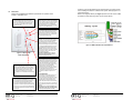
The following components (in addition to a suitable power supply) are typically
utilized to make up the inQuire™ 1000 Intercom System (see Figure 1).
Door Unit
.
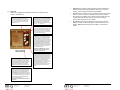
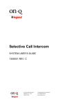
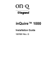
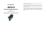
Please refer to Figure 16 to familiarize yourself with the operation of the
inQuire™ 1000 Door Unit.
Door Chime Button: When a visitor
pushes this button, the Door Chime
will be neard throughout the home at
each active intercom unit. The
occupants of the home can then press
the Door button at any intercom unit
to answer the door. The visitor will
hear the occupant over the Door Unit
speaker and be able to talk to them
over the Door Unit microphone. The
occupant may also choose to release
the electronic door latch (if equipped)
and let the visitor in.
Microphone
Speaker
Figure 16 - inQuire™1000 Door Unit Operation
Figure 1 - inQuire™ 1000 Intercom System Components
•
•
Intercom Module: This module is typically installed in the On-Q
enclosure and is considered the "brains" of the system. All Room Units,
Door Units, Patio Units and the Main Console Unit are connected directly
to the Intercom Module via "home run" style Cat 5e cabling. The
Intercom Module also supplies power to the entire inQuire™ 1000
Intercom System.
Main Console Unit: In addition to providing the same basic intercom
features found with Room Units, the Main Console Unit also includes a
bank of status LEDs which show, at a glance, Room Units that are
talking, muted, or in monitor mode. It also includes a dedicated door
release button (functional when an electronic door release device is
installed), and a talk hands free button, which allows users of Room
Units to talk without having to push their "talk" buttons.
•
Room Unit: This unit provides basic intercom communication functions
such as talk, talk to door (if Door Unit is installed), monitor and mute. Up
to 12 Room Units can be installed per system.
•
Desktop Unit: This unit provides the same functionality as a Room Unit,
but can be placed on a desktop or nightstand instead of being installed in
the wall. It is connected to any Cat 5e outlet with its supplied cable.
301 Fulling Mill Road, Suite G
Middletown, PA 17057
(800) 321-2343
© Copyright 2006 by On-Q/Legrand Inc.
All Rights Reserved
www.onqlegrand.com
Page 2
301 Fulling Mill Road, Suite G
Middletown, PA 17057
(800) 321-2343
© Copyright 2006 by On-Q/Legrand Inc.
All Rights Reserved
www.onqlegrand.com
Page 23
D.
•
Patio Unit: This unit also provides typical Room Unit functionality in a
weather resistant wall mounted package for your patio. For security
reasons, its door release functionality may be disabled.
•
Door Unit: This unit allows a visitor to the home to press the door chime
button on the unit to notify the occupants of their presence (requires
Door Chime to be installed). The occupants can then initiate a two-way
communication with the visitor and even open the door (requires
electronic door relese device, not included).
•
Door Chime: This component installs as an add-on to the Intercom
Module. It enables a chime to be heard on all the units that are not in
MUTE or MONITOR mode throughout the inQuire™ 1000 Intercom
System.
Patio Unit
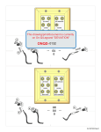
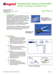
Please refer to Figure 15 to familiarize yourself with the operation of the
inQuire™ 1000 Patio Unit.
TALK: Depressing this button will allow you to
communicate with all other active units. Hold in the
TALK button while speaking, and let it go when you are
done. Your voice will be heard on the Main Console
Unit, as well as any active Room, Patio, or Desktop
Unit within the system.
ANSWER LED: This LED is located at the top of the
keypad of the Patio Unit. When lit, the LED indicates
that the microphone in the unit is active and anything
you say will be communicated through the system.
This LED will light when you are depressing the
TALK or DOOR buttons. The LED will be constantly
lit when the unit is in MONITOR mode.
DOOR: Depressing this button will allow you to
communicate with all Door Units that are part of your
system. Hold in the DOOR button while speaking
and let it go when you are done. Your voice will be
heard on any active Room, Patio, or Desktop Units
and all Door Units within the system.
Figure 15 - inQuire™
Patio Unit Operation
MUTE: Press this button once to put the Unit in MUTE
mode. Press the button again to return the Unit back to
normal mode. While in MUTE mode, both the speaker
and microphone of the unit will be inactive and the LED
to the right of the MUTE button will glow red. MUTE
mode is useful for maintaining privacy on the patio.
Multiple units can be in MUTE mode at the same time.
MONITOR: Press this button once to put the Unit in
MONITOR mode. Press the button again to return
the Unit back to normal mode. While in MONITOR
mode, the microphone is constantly active, the
speaker is disabled and any voice or noise within the
room will be heard throughout the system. The LED
to the right of the MONITOR button will glow green
when in MONITOR mode. Multiple Units can be in
MONITOR mode at the same time. This function is
useful for baby monitoring or other types of situations
which require any voice or noise in a room to be
heard throughout the system.
NOTE: When in MONITOR mode, a door bell
button push at a Door Unit will not result in a
door chime ring at the Patio Unit.
VOLUME: There are two volume control buttons
with an associated volume level LED bar. There are
20 different volume levels which are adjusted up and
down using these two buttons. Pressing the volume
up button once will increase the volume one level
higher. You may not see the LEDs change until you
press the volume up or down multiple times
(approximately every sixth button press). You can
also hold in the volume up or down button until you
have reached the desired volume level. It is
recommended that you keep the volume level in the
middle position (3 LEDs lit) for optimum sound
quality.
PATIO UNIT DISABLE: If security mode was enabled
by removing the shunt on J3 on the rear of the Intercom
Module, the Patio Unit can be disabled temporarily by
simultaneously pressing and releasing the TALK and
DOOR RELEASE buttons on the Main Console Unit. The
Patio Unit Status LED should blink slowly Red and then
Green. To re-enable the Patio Unit, again simultaneously
press and release the TALK and DOOR RELEASE
buttons on the Main Console Unit.
NOTE: There is no Door Release function enabled on
the Patio Unit.
301 Fulling Mill Road, Suite G
Middletown, PA 17057
(800) 321-2343
© Copyright 2006 by On-Q/Legrand Inc.
All Rights Reserved
www.onqlegrand.com
Page 22
301 Fulling Mill Road, Suite G
Middletown, PA 17057
(800) 321-2343
© Copyright 2006 by On-Q/Legrand Inc.
All Rights Reserved
www.onqlegrand.com
Page 3
III.
Wiring Specifications
A.
•
B.
C.
C.
Specifications
•
Minimum cable rating: Category 5 UTP, 4 pair solid conductors (24
AWG),
100 ohm, 100 Mhz, General Purpose (CM), UL listed Maximum length
per run: 325 feet
•
•
•
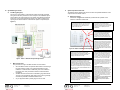
Termination standard: T568A
Terminating plug type (where necessary): Solid Conductor RJ45
Terminating block type (where available): 110-style IDC
Please refer to Figure 14 to familiarize yourself with the operation of the
inQuire™ 1000 Desktop Unit.
TALK: Depressing this button will allow you to
communicate with all other active units. Hold in the
TALK button while speaking, and let it go when you are
done. Your voice will be heard on the Main Console
Unit, as well as any active Room, Patio, or Desktop
Unit within the system.
•
•
•
Do not exceed 25 lbs. of force when pulling cable.
Do not splice cables.
Do not staple cables. Use wire ties with screw mounts to loosely secure
cabling.
•
Avoid running Cat 5 cable parallel to 120V/240V AC wiring or fixtures
within 12 inches.
•
Avoid "ganging" any intercom unit with a lighting dimmer switch. Maintain
at least 12 inches of separation from dimmer switches.
•
If you must cross AC wiring, do so at a 90 degree angle with at least 2
inches of separation.
•
•
•
Maintain a minimum 1" bend radius.
Do not untwist Cat 5 conductors more than 1/2" at any termination point.
Keep cables away from HVAC ducts, or anything with sharp edges that
could cause damage.
•
Clearly label all cabling runs at both ends. Use the distance between
your hand and your elbow as a guide to determine how far from the end
of the cable to place the label.
Unit Placement Tips
•
•
•
To minimize the likelihood of any feedback issues avoid placing units
back to back on a common wall. If units must be placed on both sides of
a common wall, then do so in a manner which avoids feedback
problems.
Do not place intercom units within the same room in the home.
Avoid any situations where the speaker of a unit points to and has a
clear line of sight to another unit's microphone.
Termination Instructions
.
All termination can be correctly completed by following the T568A pin
assignments. It is important that you accurately terminate using T568A at all
301 Fulling Mill Road, Suite G
Middletown, PA 17057
(800) 321-2343
© Copyright 2006 by On-Q/Legrand Inc.
All Rights Reserved
www.onqlegrand.com
Page 4
ANSWER LED: This LED is located at the top of the
keypad of the Room Unit. When lit, the LED indicates
that the microphone in the unit is active and anything
you say will be communicated through the system.
This LED will light when you are depressing the
TALK or DOOR buttons. The LED will be constantly
lit when the unit is in MONITOR mode.
DOOR: Depressing this button will allow you to
communicate with all Door Units that are part of your
system. Hold in the DOOR button while speaking
and let it go when you are done. Your voice will be
heard on any active Room, Patio, or Desktop Units
and all Door Units within the system.
Guidelines
Carefully plan the placement of Room Units and the Main Console Unit before
rough-in to avoid any feedback issues that are associated with audio devices.
D.
Desktop Unit
Figure 14 - inQuire™ 1000
Desktop Unit Operation
MUTE: Press this button once to put the Unit in MUTE
mode. Press the button again to return the Unit back to
normal mode. While in MUTE mode, both the speaker
and microphone of the unit will be inactive and the LED
to the right of the MUTE button will glow red. MUTE
mode is useful for maintaining privacy in a particular
room. Multiple rooms can be in MUTE mode at the same
time.
DOOR RELEASE: There is no specific button on the
Desktop Unit for the DOOR RELEASE function.
However, by depressing both the TALK and the DOOR
buttons at the same time, the Unit will engage the door
release device (not included with the Intercom System) if
a door release device is installed in conjunction with the
Intercom System. Once you let go of the TALK and
DOOR buttons, the door release device will be
disengaged, which will lock the door again.
301 Fulling Mill Road, Suite G
Middletown, PA 17057
(800) 321-2343
MONITOR: Press this button once to put the Unit in
MONITOR mode. Press the button again to return
the Unit back to normal mode. While in MONITOR
mode, the microphone is constantly active, the
speaker is disabled and any voice or noise within the
room will be heard throughout the system. The LED
to the right of the MONITOR button will glow green
when in MONITOR mode. Multiple Units can be in
MONITOR mode at the same time. This function is
useful for baby monitoring or other types of situations
which require any voice or noise in a room to be
heard throughout the system.
NOTE: When in MONITOR mode, a door bell
button push at a Door Unit will not result in a
door chime ring at the Room Unit.
VOLUME: There are two volume control buttons
with an associated volume level LED bar. There are
20 different volume levels which are adjusted up and
down using these two buttons. Pressing the volume
up button once will increase the volume one level
higher. You may not see the LEDs change until you
press the volume up or down multiple times
(approximately every sixth button press). You can
also hold in the volume up or down button until you
have reached the desired volume level. It is
recommended that you keep the volume level in the
middle position (3 LEDs lit) for optimum sound
quality.
KEYPAD BRIGHTNESS:
If the default Dim level of the backlit buttons is not
adequate for the user, then press both Volume
buttons at the same time and release them. Use the
Up or Down Volume button to brighten or dim the
default backlight level. When the desired level is
reached, either push both buttons at the same time
again to resume normal operation, or just let the Unit
time out (after about 10 seconds) to return to normal
operation.
NOTE: When in use, the Unit’s backlight level is
at full brightness and returns to the set backlight
Dim level upon timeout (about 10 seconds).
© Copyright 2006 by On-Q/Legrand Inc.
All Rights Reserved
www.onqlegrand.com
Page 21
B.
Room Unit
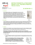
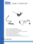
locations. There are two different types of terminations you will encounter
when installing the inQuire™ 1000 Intercom System: RJ45 plugs and 110
punchdown blocks.
Please refer to Figure 13 to familiarize yourself with the operation of the
inQuire™ 1000 Room Unit.
Refer to the diagrams below (see Figure 2) which show the correct T568A
termination for both RJ45 plugs and 110 punchdown blocks.
TALK: Depressing this button will allow you to
communicate with all other active units. Hold in the
TALK button while speaking, and let it go when you are
done. Your voice will be heard on the Main Console
Unit, as well as any active Room, Patio, or Desktop
Unit within the system.
ANSWER LED: This LED is located at the top of the
keypad of the Room Unit. When lit, the LED indicates
that the microphone in the unit is active and anything
you say will be communicated through the system.
This LED will light when you are depressing the
TALK or DOOR buttons. The LED will be constantly
lit when the unit is in MONITOR mode.
DOOR: Depressing this button will allow you to
communicate with all Door Units that are part of your
system. Hold in the DOOR button while speaking
and let it go when you are done. Your voice will be
heard on any active Room, Patio, or Desktop Units
and all Door Units within the system.
Figure 13 - inQuire™ 1000
Room Unit Operation
MUTE: Press this button once to put the Unit in MUTE
mode. Press the button again to return the Unit back to
normal mode. While in MUTE mode, both the speaker
and microphone of the unit will be inactive and the LED
to the right of the MUTE button will glow red. MUTE
mode is useful for maintaining privacy in a particular
room. Multiple rooms can be in MUTE mode at the same
time.
DOOR RELEASE: There is no specific button on the
Room Unit for the DOOR RELEASE function. However,
by depressing both the TALK and the DOOR buttons at
the same time, the Unit will engage the door release
device (not included with the Intercom System) if a door
release device is installed in conjunction with the Intercom
System. Once you let go of the TALK and DOOR buttons,
the door release device will be disengaged, which will lock
the door again.
301 Fulling Mill Road, Suite G
Middletown, PA 17057
(800) 321-2343
© Copyright 2006 by On-Q/Legrand Inc.
All Rights Reserved
www.onqlegrand.com
MONITOR: Press this button once to put the Unit in
MONITOR mode. Press the button again to return
the Unit back to normal mode. While in MONITOR
mode, the microphone is constantly active, the
speaker is disabled and any voice or noise within the
room will be heard throughout the system. The LED
to the right of the MONITOR button will glow green
when in MONITOR mode. Multiple Units can be in
MONITOR mode at the same time. This function is
useful for baby monitoring or other types of situations
which require any voice or noise in a room to be
heard throughout the system.
NOTE: When in MONITOR mode, a door bell
button push at a Door Unit will not result in a
door chime ring at the Room Unit.
Figure 2 - T568A Termination Color Code Reference
VOLUME: There are two volume control buttons
with an associated volume level LED bar. There are
20 different volume levels which are adjusted up and
down using these two buttons. Pressing the volume
up button once will increase the volume one level
higher. You may not see the LEDs change until you
press the volume up or down multiple times
(approximately every sixth button press). You can
also hold in the volume up or down button until you
have reached the desired volume level. It is
recommended that you keep the volume level in the
middle position (3 LEDs lit) for optimum sound
quality.
KEYPAD BRIGHTNESS:
If the default Dim level of the backlit buttons is not
adequate for the user, then press both Volume
buttons at the same time and release them. Use the
Up or Down Volume button to brighten or dim the
default backlight level. When the desired level is
reached, either push both buttons at the same time
again to resume normal operation, or just let the Unit
time out (after about 10 seconds) to return to normal
operation.
NOTE: When in use, the Unit’s backlight level is
at full brightness and returns to the set backlight
Dim level upon timeout (about 10 seconds).
Page 20
301 Fulling Mill Road, Suite G
Middletown, PA 17057
(800) 321-2343
© Copyright 2006 by On-Q/Legrand Inc.
All Rights Reserved
www.onqlegrand.com
Page 5
IV.
System Wiring Overview
A.
V.
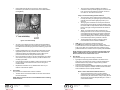
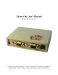
Pre-Wiring (Rough-In)
The rough-in of the inQuire™ 1000 Intercom System should be completed
during the construction phase of the home and prior to the installation by the
home builder of any wall covering such as drywall. The following section will
instruct you on the proper methods to pre-wire your cable and rough-in the
opening for the various inQuire™ 1000 Intercom System components (see
Figure 3).
System Operational Overview
The following section explains the various functions and operational features of the
components of the inQuire 1000™.
A.
Main Console Unit
Please refer to Figure 12 to familiarize yourself with the operation of the
inQuire™ 1000 Main Console Unit.
TALK: Depressing this button will allow you to
communicate with all other active units. Hold in the TALK
button while speaking, and let it go when you are done.
Your voice will be heard on any active Room, Patio, or
Desktop Unit within the system.
ANSWER LED: This LED is located at the top of the
keypad. When lit, the LED indicates that the
microphone in the unit is active and anything you say
will be communicated through the system. This LED
will light when you are depressing the TALK or
DOOR buttons.
DOOR: Depressing this button will allow you to
communicate with all Door Units that are part of
your system. Hold in the DOOR button while
speaking and let it go when you are done. Your
voice will be heard on any active Room, Patio, or
Desktop Units and all Door Units within the system.
Figure 12 - inQuire™ 1000 Main Console Operation
DOOR RELEASE: Pressing the DOOR RELEASE button will
engage the door release device (not included with the
Intercom System) if a door release device is installed. Once
you let go of the button, the door release device will be
disengaged, which will lock the door again.
Figure 3 - inQuire™ 1000 Intercom System Rough-In Phase
1.
Main Console Unit
The procedure to rough-in the Main Console Unit is as follows:
•
•
•
Since the Main Console Unit provides status LEDs for monitoring of
the entire intercom system, it is recommended that this unit is
installed in a central location. Traditionally, this unit is installed in
the kitchen area. Verify the location with the homeowner before
proceeding.
The Main Console Unit mounts in a standard 3 gang electrical box.
The use of an enclosed box rather than an open mud ring will help
minimize the potential for feedback between units.
Any UL approved metal or plastic gang box can be used.
301 Fulling Mill Road, Suite G
Middletown, PA 17057
(800) 321-2343
© Copyright 2006 by On-Q/Legrand Inc.
All Rights Reserved
www.onqlegrand.com
Page 6
PATIO UNIT DISABLE: If a Patio Unit is installed in Port #11
and security mode was enabled by removing the shunt on J3
on the rear of the Intercom Module, the Patio Unit can be
disabled temporarily by simultaneously pressing and releasing
the TALK and DOOR RELEASE buttons on the Main Console
Unit. The Patio Unit Status LED should blink slowly Red and
then Green. To re-enable the Patio Unit, again simultaneously
press and release the TALK and DOOR RELEASE buttons on
the Main Console Unit.
STATUS LEDs: Each LED indicates the status of each
Room Unit in the system. A GREEN light indicates that the
Room Unit’s Talk or Door button is depressed and someone
is talking with the unit. A RED light indicates that the Room
Unit is in MUTE mode and that all speaker and microphone
functions of the unit are disabled. An ORANGE light indicates
that the unit is in Monitor mode and its microphone is
currently active. Pre-printed and blank labels are included in
the package to identify LEDs.
301 Fulling Mill Road, Suite G
Middletown, PA 17057
(800) 321-2343
© Copyright 2006 by On-Q/Legrand Inc.
All Rights Reserved
www.onqlegrand.com
TALK HANDS FREE: Press and hold this button
while talking to put all active Room Units in Hands
Free Mode. All active (not in Mute or Monitor Mode)
Room Unit’s microphones are activated, so that
other intercom users can communicate without
pressing their TALK buttons. The Hands Free
Mode stays in effect for 20-30 seconds or until the
TALK HANDS FREE button on the Main Console is
pressed again.
VOLUME: There are two volume control buttons
with an associated volume level LED bar. There are
20 different volume levels which are adjusted up
and down using these two buttons. Pressing the
volume up button once will increase the volume one
level higher. You may not see the LEDs change
until you press the volume up or down multiple
times (approximately every sixth button press). You
can also hold in the volume up or down button until
you have reached the desired volume level. It is
recommended that you keep the volume level in the
middle position (3 LEDs lit) for optimum sound
quality.
KEYPAD BRIGHTNESS:
If the default Dim level of the backlit buttons is not
adequate for the user, then press both Volume
buttons at the same time and release them. Use the
Up or Down Volume button to brighten or dim the
default backlight level. When the desired level is
reached, either push both buttons at the same time
again to resume normal operation, or just let the
Unit time out (after about 10 seconds) to return to
normal operation.
NOTE: When in use, the Unit’s backlight level is
at full brightness and returns to the set
backlight Dim level upon timeout (about 10
seconds).
Page 19
NOTE: Only door release devices that operate using 12V DC and
have a maximum current draw of 500mA are to be used with the
inQuire™ 1000 Intercom System.
2.
Figure 11 - Install Intercom Module into Enclosure
•
•
•
•
The 3 gang box should be installed at the same height as electrical
switch boxes in the home.
•
A total of TWO Cat 5e runs are required to operate the Main
Console Unit.
•
Run TWO Cat 5e cable runs from the 3 gang box directly to the
enclosure where the Intercom Module will be installed. You must
label both ends of the cable runs for the Main Console Unit to
ensure proper termination during the trim-out. Label one cable
"Main 1" and the other cable "Main 2". Follow the wiring guidelines
listed in this manual to ensure a quality cable installation.
Room Unit(s)
•
Insert the Intercom Module into the mounting bracket and insert the
bracket into the On-Q enclosure. Secure the Intercom Module to the
bracket by depressing each plunger at each corner of the Intercom
Module.
DO NOT apply power to the Intercom Module until all RJ45 plugs
are seated in the correct jacks on the Intercom Module.
•
Plug in all RJ45 connectors for Room and Desktop Units into the
appropriate jacks on the Intercom Module according to your cable
labeling.
If utilized, plug the RJ45 connector for the Patio Unit into the jack
labeled "11/PATIO UNIT" on the Intercom Module.
•
The Main Console Unit cables should plug into the correct MAIN
jacks according the the cable labeling.
•
If 3 total Door Units will be used then the third Door Unit cable must
plug into the jack labeled 12/DOOR 3 on the Intercom Module and
you must remove a shorting block from pin #1 of JP100 on the rear
of the Intercom Module (see Figure 11).
•
Pin #2 of JP100 controls whether you want to hear the chime sound
associated with the optional Door Chime at the Door Unit or not. If
you do want to hear the Door Chime at the Door Unit when the
doorbell button is pressed, remove the jumper from pin #2 (see
Figure 11).
Pin #3 of JP100 is associated with Patio Unit functionality. If you are
using a Patio Unit, plug it into port #11/PATIO UNIT and remove the
jumper from pin #3 of JP100. This is also called “Security Mode”,
and allows the Patio Unit to be temporarily disabled from the Main
Console by simultaneously pressing the TALK and DOOR
RELEASE buttons. If the jumper on pin #3 is left on, port #11 is
configured to support a standard Room Unit.
NOTE: For obvious security reasons, there is no door release
function enabled on a Patio Unit.
•
To avoid damage from debris during or after construction, use an
enclosed gang box.
The procedure to rough-in the Room Unit(s) is as follows:
•
•
•
3.
Typically the Room Unit(s) will be installed on the same wall as the
door to the room. Verify each Room Unit location with the
homeowner before proceeding. Avoid installing Room Units in the
same stud cavity on opposite sides of the wall to prevent feedback
problems.
The Room Unit mounts in a standard 2 gang electrical box. The use
of an enclosed box rather than an open mud ring will help minimize
the potential for feedback between units.
•
•
Any UL approved metal or plastic gang box can be used.
To avoid damage from debris during construction or after
construction, use a gang box that will completely enclose the unit.
•
The 2 gang box should be installed at the same height as the
electrical switch boxes in the home.
•
•
ONE Cat 5e run is required to operate the Room Unit.
Run ONE Cat 5e cable from the 2 gang box directly to the
enclosure where the Intercom Module will be installed. Label both
ends of your cable run to indicate Room Unit number (ex: "Room
Unit 5). Follow the wiring guidelines listed in this manual to ensure a
quality cable installation.
•
Repeat these instructions for each and every Room Unit that will be
installed in the system (maximum of 12).
Desktop Unit(s)
The procedure to rough-in the Desktop Unit(s) is as follows:
•
•
•
•
Typically the Desktop Unit(s) will be connected to a Cat5e outlet on
a wall where the desk or nightstand will be placed.. Verify each
Desktop Unit location with the homeowner before proceeding
The Cat 5e outlet for the Desktop Unit typically mounts in a
standard 1 gang electrical box or mud ring.
Any UL approved metal or plastic gang box can be used.
The 1 gang box should be installed at the same height as the
electrical outlet boxes in the home.
Apply power to the Intercom Module and verify system functionality.
301 Fulling Mill Road, Suite G
Middletown, PA 17057
(800) 321-2343
© Copyright 2006 by On-Q/Legrand Inc.
All Rights Reserved
www.onqlegrand.com
Page 18
301 Fulling Mill Road, Suite G
Middletown, PA 17057
(800) 321-2343
© Copyright 2006 by On-Q/Legrand Inc.
All Rights Reserved
www.onqlegrand.com
Page 7
4.
•
•
ONE Cat 5e run is required to operate the Desktop Unit.
Run ONE Cat 5e cable from the 1 gang box directly to the
enclosure where the Intercom Module will be installed. Label both
ends of your cable run to indicate Desktop Unit number (ex:
"Desktop Unit 5). Follow the wiring guidelines listed in this manual
to ensure a quality cable installation.
•
Repeat these instructions for each and every Desktop Unit that will
be installed in the system (maximum of 12).
•
Place the Door Chime circuit board on the rear of the Intercom
Module so that the two mounting holes on the Door Chime circuit
board are seated on the Intercom Module threaded mounting studs
(see Figure 10).
Patio Unit(s)
The procedure to rough-in the Patio Unit(s) is as follows:
•
•
Typically the Patio Unit(s) will be installed on the exterior of the
home next to a patio door. Verify the Patio Unit(s) location(s) with
the homeowner before proceeding.
Since the Patio Unit will most likely be installed on the exterior of
the home and will be exposed to weather conditions, these
instructions must be followed to ensure a quality installation.
Brick or other cement-based material exteriors:
•
The recommended box to use is a 2 gang outdoor
weatherproof box. This box should be of the type that is
made of heavy die-cast aluminum. Using a heavy die-cast
aluminum box will provide adequate strength in a brick or
cement-based exterior.
Figure 10 - Install Door Chime
•
Vinyl or wood based siding material exteriors:
•
•
•
If possible, use a heavy duty die-cast aluminum 2 gang
box if it can be securely mounted to the interior framing. If
this is not possible then it is recommended that you use a
heavy duty metal 2 gang box that can be securely
mounted to the interior framing of the home.
To ensure the 2 gang box that will be used to house the Patio Unit
is roughed in correctly, communication with the building contractor
who is responsible for the exterior finish of the home is highly
recommended.
•
7.
•
•
The masonry contractor must be provided with specific
instructions as to how the 2 gang box should be installed
including location, correct positioning, and proper depth.
If possible, clearly mark this information on the home's
exterior insulation board or vapor barrier material to serve
as a reminder to the mason.
The correct positioning of the 2 gang box may not be
obvious to the masonry contractor. Ensure that the
masonry contractor knows which edge of the box is up
and which edge is down so that the Patio Unit can be
installed in the correct vertical position.
301 Fulling Mill Road, Suite G
Middletown, PA 17057
(800) 321-2343
© Copyright 2006 by On-Q/Legrand Inc.
All Rights Reserved
www.onqlegrand.com
Page 8
Use the included hex nuts and washers to secure the Door Chime
circuit board to the Intercom Module mounting studs.
Intercom Module
The procedure to install the Intercom Module is as follows:
•
Brick or other cement-based material exteriors:
•
Ensure that the Door Chime's pin array socket is properly aligned
with the pin array (labeled JP203) on the Intercom Module.
Apply slight downward pressure to the Door Chime circuit board to
securely seat the pin aaray connections together.
Terminate all cable runs from Room Units, Desktop Units, Patio
Units, Door Units, and the Main Console Unit using RJ45 plugs.
Follow the T568A wiring standard which can be found in this
manual.
NOTE: The proper termination of the RJ45 plugs is critical the
correct operation of the inQuire™ 1000 Intercom System. Incorrect
termination could result in damage or improper operation of the
system.
•
If you are using a door release device then you must terminate the
two conductors from your door release device to the Intercom
Module by routing the conductors through the mounting bracket
before inserting the Intercom Module into its mounting bracket.The
door release device conductors are to be terminated to the blue
mounting block (JP202) located on the rear circuit board of the
Intercom Module. Maintain correct polarity (see Figure 11).
301 Fulling Mill Road, Suite G
Middletown, PA 17057
(800) 321-2343
© Copyright 2006 by On-Q/Legrand Inc.
All Rights Reserved
www.onqlegrand.com
Page 17
•
•
Untwist cable pairs but be sure to leave 1/2" twist in the pairs
between the punchdown block and the start of the cable insulation
(see Figure 9).
The 2 gang box should be installed by the masonry
contractor so that it protrudes slightly from the face of the
brick. The box should protrude no less than 1/8" but no
more than 1/4" from the face of the brick.
Vinyl or wood based siding material exteriors:
•
•
Figure 9 - Trim-Out Door Unit(s)
6.
•
As shown in the diagram, the Cat 5e cable must be terminated so
that the cable is routed to the punchdown block so that the unit can
be installed into a standard gang box while maintaining proper bend
radius.
•
Following T568A wiring color code, place the pairs firmly into their
appropriate positions on the punchdown block. Ensure that the
individual conductors are seated tightly enough to allow you to
punch them down without having to hold them in place.
•
Using a punchdown tool with a 110 style cutting blade, punch down
each conductor firmly enough to allow any excess conductor to be
cut away by the blade.
•
Insert the Door Unit with the gasket in position and the Cat e5 cable
into the 2 gang box and secure the unit to the box using the 4
included screws.
•
Repeat these instruction for any additional Door Units in your
inQuire™ 1000 Intercom System.
The Door Chime circuit board installs onto the rear circuit board of
the Intercom Module.
NOTE: Remove power from the front of the Module before installing
the Door Chime.
© Copyright 2006 by On-Q/Legrand Inc.
All Rights Reserved
www.onqlegrand.com
Ideally, you would want the siding contractor to use
flashing and make use of J-channel around the perimeter
of the Patio Unit and 2 gang box to provide an attractive
and weatherproof siding installation. Siding contractors
should use flashing and J-channel around the perimeter
of the Patio Unit just as they would with a window.
•
Communication with the siding contractor is highly
recommended to ensure a smooth installation.
ONE Cat 5e run is required to operate the Patio Unit.
Run ONE Cat 5e cable from the 2 gang box directly to the
enclosure where the Intercom Module will be installed. Label both
ends of your cable run to indicate "Patio Unit". Follow the wiring
guidelines listed in this manual to ensure a quality cable installation.
5.
Door Unit(s)
The procedure to rough-in the Door Unit(s) is as follows:
•
Typically the Door Unit(s) will be installed on the exterior of the
home next to an entrance door, where you would normally find a
standard doorbell. Verify the Door Unit(s) location(s) with the
homeowner before proceeding.
Since the Door Unit will most likely be installed on the exterior of the
home and will be exposed to weather conditions, these instructions
must be followed to ensure a quality installation.
Brick or other cement-based material exteriors:
The procedure to install the Door Chime is as follows:
301 Fulling Mill Road, Suite G
Middletown, PA 17057
(800) 321-2343
•
NOTE: The Patio Unit should be connected to the RJ45 jack that is
labeled 11/PATIO UNIT. This will reduce the maximum number of
Room Units that can be installed from 12 to 11.
•
Door Chime
•
•
•
The 2 gang box can be roughed in to the exterior of the
home by first cutting an opening through the exterior base
material of the home that is slightly larger than your 2
gang box.
The 2 gang box should then be securely mounted to the
interior framing of the exterior wall and protrudes through
the exterior wall at a depth that will need to be determined
based on the type of siding that will finish the outside of
the wall.
Page 16
•
The recommended box to use is a 2 gang outdoor
weatherproof box. This box should be of the type that is
made of heavy die-cast aluminum. Using a heavy die-cast
aluminum box will provide adequate strength in a brick or
cement-based exterior.
301 Fulling Mill Road, Suite G
Middletown, PA 17057
(800) 321-2343
© Copyright 2006 by On-Q/Legrand Inc.
All Rights Reserved
www.onqlegrand.com
Page 9
•
Vinyl or wood based siding material exteriors:
•
•
If possible, use a heavy duty die-cast aluminum 2 gang
box if it can be securely mounted to the interior framing. If
this is not possible then it is recommended that you use a
heavy duty metal 2 gang box that can be securely
mounted to the interior framing of the home.
Untwist cable pairs but be sure to leave 1/2" twist in the pairs
between the punchdown block and the start of the cable insulation
To ensure the 2 gang box that will be used to house the Door Unit is
roughed in correctly, communication with the building contractor
who is responsible for the exterior finish of the home is highly
recommended.
Brick or other cement-based material exteriors:
•
•
The masonry contractor must be provided with specific
instructions as to how the 2 gang box should be installed
including location, correct positioning, and proper depth.
If possible, clearly mark this information on the home's
exterior insulation board or vapor barrier material to serve
as a reminder to the mason.
•
The correct positioning of the 2 gang box may not be
obvious to the masonry contractor. Ensure that the
masonry contractor knows which edge of the box is up
and which edge is down so that the Door Unit can be
installed in the correct vertical position.
•
The 2 gang box should be installed by the masonry
contractor so that it protrudes slightly from the face of the
brick. The box should protrude no less than 1/8" but no
more than 1/4" from the face of the brick.
Figure 8 - Trim-Out Patio Unit(s)
(see Figure 8).
•
Vinyl or wood based siding material exteriors:
•
•
•
•
•
The 2 gang box can be roughed in to the exterior of the
home by first cutting an opening through the exterior base
material of the home that is slightly larger than your 2
gang box.
The 2 gang box should then be securely mounted to the
interior framing of the exterior wall and protrudes through
the exterior wall at a depth that will need to be determined
based on the type of siding that will finish the outside of
the wall.
Ideally, you would want the siding contractor to use
flashing and make use of J-channel around the perimeter
of the Door Unit and 2 gang box to provide an attractive
and weatherproof siding installation. Siding contractors
should use flashing and J-channel around the perimeter
of the Door Unit just as they would with a window.
Communication with the siding contractor is highly
recommended to ensure a smooth installation.
•
5.
•
Using a punchdown tool with a 110 style cutting blade, punch down
each conductor firmly enough to allow any excess conductor to be
cut away by the blade.
•
Insert the Patio Unit and the Cat e5 cable into the 2 gang box and
secure the unit to the box using the 4 included screws.
Door Unit(s)
The procedure to trim-out the Door Unit(s) is as follows:
•
•
ONE Cat 5e run is required to operate the Door Unit.
•
301 Fulling Mill Road, Suite G
Middletown, PA 17057
(800) 321-2343
© Copyright 2006 by On-Q/Legrand Inc.
All Rights Reserved
www.onqlegrand.com
Page 10
As shown in the diagram, the Cat 5e cable must be terminated so
that the cable is routed to the punchdown block so that the unit can
be installed into a standard gang box while maintaining proper bend
radius.
Following T568A wiring color code, place the pairs firmly into their
appropriate positions on the punchdown block. Ensure that the
individual conductors are seated tightly enough to allow you to
punch them down without having to hold them in place.
Make sure that the included weather proofing gasket is placed over
the Door Unit circuit board and speaker before terminating the Cat
5e cable (see Figure 9).
Locate the Cat 5e cable in the roughed in 2 gang box that you
labeled as "Door Unit X" where X is the door unit number.
Strip back approximately 2" of insulation from the Cat 5e cable.
301 Fulling Mill Road, Suite G
Middletown, PA 17057
(800) 321-2343
© Copyright 2006 by On-Q/Legrand Inc.
All Rights Reserved
www.onqlegrand.com
Page 15
3.
•
Insert the Room Unit and the Cat 5e cable into the 2 gang box and
secure the unit to the box using the 4 included screws. Attach a 2
gang decor plate to the unit to complete the installation.
•
Repeat these instructions for all the Room Units in your inQuire™
1000 Intercom System.
Desktop Unit(s)
The procedure to trim-out the Desktop Unit(s) is as follows:
•
•
•
•
Run ONE Cat 5e cable from the 2 gang box directly to the
enclosure where the Intercom Module will be installed. Label both
ends of your cable run to indicate Door Unit number (ex: "Door Unit
1). Follow the wiring guidelines listed in this manual to ensure a
quality cable installation.
•
Repeat these instructions for each and every Door Unit that will be
installed in the system (maximum of 3).
NOTE: Up to three Door Units can be installed. The installation of a
third Door Unit requires that you use the RJ45 jack that is labeled
12/DOOR 3. This will reduce the maximum number of Room Units
that can be installed from 12 to 11.
Locate a Cat 5e cable in a roughed in 1 gang box labeled as
"Desktop Unit X" (X is the Desktop Unit number).
Strip approximately 2" of insulation from the Cat 5e cable.
Untwist cable pairs but be sure to leave 1/2" twist in the pairs
between the punchdown insert and the start of the cable insulation
6.
Intercom Module and Door Chime
0.
The rough-in of the On-Q Enclosure that will house the Intercom Module
and Door Chime will need to be completed per the enclosure's
installation instructions. There is no further rough-in work required for the
Intercom Module and the Door Chime since these components will
mount directly in the On-Q Enclosure during trim-out.
NOTE: The Door Chime mounts onto the back of the Intercom
Module and does not require its own, separate enclosure space.
Figure 7 - Trim-Out Desktop Unit(s)
(see Figure 7).
•
•
4.
Following T568A wiring color code, place the pairs firmly into their
appropriate positions on the punchdown insert. Ensure that the
individual conductors are seated tightly enough to allow you to
punch them down without having to hold them in place.
Using a punchdown tool with a 110 style cutting blade, punch down
each conductor firmly enough to allow any excess conductor to be
cut away by the blade.
•
Snap the insert into the wallplate or strap and secure them in the 1
gang box using the included screws. Attach a 1 gang plate (if
necessary) to complete the installation.
•
•
Plug the Desktop Unit into the installed Cat 5e outlet.
Repeat these instructions for all the Desktop Units in your inQuire™
1000 Intercom System.
Patio Unit(s)
The procedure to trim-out the Patio Unit(s) is as follows:
•
•
Locate the Cat 5e cable in the roughed in 2 gang box that you
labeled as "Patio Unit".
Strip back approximately 2" of insulation from the Cat 5e cable.
301 Fulling Mill Road, Suite G
Middletown, PA 17057
(800) 321-2343
© Copyright 2006 by On-Q/Legrand Inc.
All Rights Reserved
www.onqlegrand.com
Page 14
301 Fulling Mill Road, Suite G
Middletown, PA 17057
(800) 321-2343
© Copyright 2006 by On-Q/Legrand Inc.
All Rights Reserved
www.onqlegrand.com
Page 11
B.
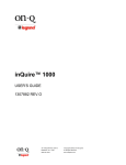
Final Wiring (Trim-Out)
.
The trim-out of the system should be completed after wall coverings have
been finalized. The following section will instruct you on the proper methods to
finish the installation of the various inQuire™ 1000 Intercom System
components.
1.
Main Console Unit
The procedure to trim-out the Main Console Unit is as follows:
•
•
•
Locate the Cat 5e cable in the roughed in 3 gang box that you
labeled as "Main 1".
Strip back approximately 2" of insulation from the Cat 5e cable.
Untwist cable pairs and place them next to each other in colorcoded order according to theT568A standard and insert the wires
into an RJ45 plug.
•
Crimp the cable into the RJ45 plug with a proper RJ45 crimp tool.
•
Plug the terminated "Main 1" cable into the RJ45 jack on the rear of
the Main Console Unit "Main 1" (see Figure 4).
Figure 5 - Label Each Location on Main Console
2.
Room Unit(s)
The procedure to trim-out the Room Unit(s) is as follows:
•
•
•
Locate a Cat 5e cable in a roughed in 2 gang box labeled as "Room
Unit X" (X is the Room Unit number).
Strip approximately 2" of insulation from the Cat 5e cable.
Untwist cable pairs and place them next to each other in colorcoded order according to theT568A standard and insert the wires
into an RJ45 plug.
•
Crimp the RJ45 plug onto the cable with a proper RJ45 crimp tool.
•
Plug the terminated "Room Unit X" cable into the RJ45 jack on the
rear of the Room Unit (see Figure 6).
Figure 4 - inQuire™ 1000 Intercom System Trim-Out Phase
•
Repeat the previous steps for the cable labeled "Main 2".
•
Insert the Main Console Unit and the Cat 5e cables into the 3 gang
box and secure the unit to the box using the 6 included screws.
Attach a 3 gang decor plate to the unit to complete the installation.
•
Terminate the other end of each labeled Cat 5e cable in the
enclosure and plug the "Main 1" cable into the jack on the Intercom
Module labeled "MAIN 1" and plug the "Main 2" cable into the jack
on the Intercom Module labeled "MAIN 2".
•
Once all Units have been trimmed-out, use the provided location
labeling sheet (R1596) to label each location in the status section
on the front of the Main Console (see Figure 5). This really helps
make your system installation much more professional.
301 Fulling Mill Road, Suite G
Middletown, PA 17057
(800) 321-2343
© Copyright 2006 by On-Q/Legrand Inc.
All Rights Reserved
www.onqlegrand.com
Page 12
Figure 6 - Plug Room Cable into Room Unit
301 Fulling Mill Road, Suite G
Middletown, PA 17057
(800) 321-2343
© Copyright 2006 by On-Q/Legrand Inc.
All Rights Reserved
www.onqlegrand.com
Page 13