1
S1080 HD™ NETWORK CAMERA User’s Guide S1080 Series: Ultra Low Light Camera BETTER VIDEO ALL DAY/ALL NIGHT Unpublished copyright @2013 GBOT Technology, Inc. All rights reserved. This document is the property of and contains information proprietary to GBOT Technology, Inc. No part of this document may be reproduced, transmitted, transcribed, stored in a retrieval system, or translated into any language or computer language, in any form or by any means, electronic, mechanical, magnetic, optical, chemical, manual or otherwise, without the written permission of GBOT Technology, Inc. GBOT TECHNOLOGY LICENSE AGREEMENT Notice to Buyer (hereafter “End User”: Carefully read the following legal agreement. Opening the software package provided with the equipment constitutes your acceptance of these terms. If you do not agree to the terms of this agreement, promptly return the software and the equipment unopened and unused (including written materials and containers) to the location where you obtained them for a full refund. United States Offices and Customer Service GBOT Technology (US) Incorporated Address: 1150 Bayhill Drive Suite 111 San Bruno, CA 94066 USA Phone: +1 650 200 3838 E-mail: [email protected] [email protected] S1080 User’s Manual U/M-2013-1000 Revision B TABLE OF CONTENTS Section/Title 1.0 1.1 1.2 2.0 2.1 2.2 2.3 3.0 4.0 5.0 5.1 5.2 5.3 6.0 6.1 6.2 7.0 7.1 7.2 7.3 7.4 8.0 8.1 8.2 8.3 8.4 8.5 Page READY CAMERA FOR INSTALLATION ............................................................................................................ 1 Configure GBOT S1080 IP Network Camera for the Lens Type .......................................................................... 1 Reset Factory Default Values ............................................................................................................................... 1 1.2.1 RESET Button ............................................................................................................................................. 1 INSTALLATION ................................................................................................................................................... 3 Camera Connected Directly to a Personal Computer .......................................................................................... 3 Standalone POE Switch Installation ................................................................................................................... 11 UPNP- and DHCP-Enabled Network Installation ............................................................................................... 12 CONFIGURE INTERNET EXPLORER AFTER FIRMWARE UPDATE ............................................................. 16 IP ADDRESS PROVISIONING VIA DHCP ........................................................................................................ 20 STATIC IP ADDRESS PROVISIONING (PC SIDE)........................................................................................... 22 Manually Configure IP Address .......................................................................................................................... 22 View IP Address Setting via USBconf Utility ...................................................................................................... 22 Set Static IP Address via Web Browser GUI (Camera Side) .............................................................................. 25 WEB BROWSER GUI SCREEN ........................................................................................................................ 27 Live Video Streaming Screen ............................................................................................................................. 27 6.1.1 Select Stream Drop-Down List .................................................................................................................. 27 6.1.2 Display all Streams Checkbox ................................................................................................................... 28 6.1.3 Enable Display all streams ........................................................................................................................ 28 6.1.4 Icons .......................................................................................................................................................... 29 6.1.5 Logout Button ............................................................................................................................................ 33 navigation panel ................................................................................................................................................. 33 ADD/EDIT USERS ............................................................................................................................................. 34 Change Password .............................................................................................................................................. 34 User Information ................................................................................................................................................. 35 Edit/Delete User ................................................................................................................................................. 35 Access Control Settings ..................................................................................................................................... 36 VIDEO IMAGE SETTINGS ................................................................................................................................ 37 Playback Latency ............................................................................................................................................... 37 Video Screen Settings ........................................................................................................................................ 37 8.2.1 Camera ...................................................................................................................................................... 38 8.2.2 Stream Type .............................................................................................................................................. 38 8.2.3 Codec Combo ............................................................................................................................................ 38 8.2.4 Resolution .................................................................................................................................................. 38 8.2.5 H.264 Profile .............................................................................................................................................. 39 8.2.6 Local Display Video ................................................................................................................................... 39 8.2.7 Mirror ......................................................................................................................................................... 39 Video File ........................................................................................................................................................... 39 8.3.1 Stream ....................................................................................................................................................... 39 8.3.2 Video File Size ........................................................................................................................................... 39 Stream 1, 2, and 3 Screens ................................................................................................................................ 40 8.4.1 Frame Rate ................................................................................................................................................ 40 8.4.2 Bit Rate ...................................................................................................................................................... 40 8.4.3 Rate Control .............................................................................................................................................. 40 8.4.4 Quality Factor ............................................................................................................................................ 41 Overlay Setting ................................................................................................................................................... 41 8.5.1 Date ........................................................................................................................................................... 41 8.5.2 Time........................................................................................................................................................... 41 8.5.3 Logo........................................................................................................................................................... 41 August 22, 2013 Company Proprietary Page i of viii U/M-2013-1000 Revision B S1080 User’s Manual 8.5.4 Text............................................................................................................................................................ 41 8.5.5 Detailed Info .............................................................................................................................................. 41 8.6 Save Changes .................................................................................................................................................... 41 9.0 VIDEO SCREEN’S ADVANCED SETTINGS ..................................................................................................... 42 9.1 Stream 1, 2, and 3 Screens ................................................................................................................................ 42 9.1.1 IP Ratio ...................................................................................................................................................... 43 9.1.2 Force I Frame ............................................................................................................................................ 43 9.1.3 QP Value ................................................................................................................................................... 43 9.1.4 Encode Preset ........................................................................................................................................... 43 9.1.5 Packet Size ................................................................................................................................................ 43 9.2 Enable Region of Interest ................................................................................................................................... 44 9.2.1 Face Detection........................................................................................................................................... 44 10.0 ADVANCED FEATURES SETTINGS ................................................................................................................ 45 10.1 Motion Detection Setting .................................................................................................................................... 45 10.1.1 Zone Selection ........................................................................................................................................... 46 10.1.2 Sensitivity .................................................................................................................................................. 46 10.1.3 Customized Threshold ............................................................................................................................... 46 10.1.4 Enable Motion Window OSD Indication ..................................................................................................... 46 10.2 Region of Privacy Setting ................................................................................................................................... 48 10.2.1 Zone Selection – Region of Privacy ........................................................................................................... 48 10.3 Face Detect Setting ............................................................................................................................................ 49 10.4 Region of Interest ............................................................................................................................................... 49 10.4.1 Confidence Level ....................................................................................................................................... 49 10.4.2 Direction .................................................................................................................................................... 50 10.5 Privacy Mask Setting .......................................................................................................................................... 50 11.0 CAMERA SETTINGS ......................................................................................................................................... 51 11.1 Lighting Conditions ............................................................................................................................................. 51 11.1.1 Brightness .................................................................................................................................................. 51 11.1.2 Contrast ..................................................................................................................................................... 51 11.1.3 Saturation .................................................................................................................................................. 51 11.1.4 Sharpness ................................................................................................................................................. 51 11.1.5 Backlight .................................................................................................................................................... 52 11.1.6 Flicker Control............................................................................................................................................ 52 11.1.7 White Balance ........................................................................................................................................... 52 11.1.8 Day/Night ................................................................................................................................................... 52 11.1.9 Histogram .................................................................................................................................................. 52 11.1.10 Video Stabilization ..................................................................................................................................... 52 11.2 Lens Distortion Correction .................................................................................................................................. 53 12.0 CAMERA – ADVANCED SETTINGS ................................................................................................................ 54 12.1 De-noise ............................................................................................................................................................. 54 12.2 EV -/+ ................................................................................................................................................................ 54 12.3 Dynamic Range Enhancement ........................................................................................................................... 54 12.4 Frame Rate Base ............................................................................................................................................... 55 12.5 Capture Frame Rate Priority .............................................................................................................................. 55 12.5.1 Max Gain ................................................................................................................................................... 55 12.6 Quality Priority .................................................................................................................................................... 55 12.7 Manual Mode ..................................................................................................................................................... 56 12.7.1 Gain ........................................................................................................................................................... 56 13.0 PAN/TILT ........................................................................................................................................................... 57 13.1 Pan Speed ......................................................................................................................................................... 57 13.2 Tilt Speed ........................................................................................................................................................... 57 13.3 Zoom Speed ....................................................................................................................................................... 57 13.4 Focus Speed ...................................................................................................................................................... 57 Page ii of viii Company Proprietary August 22, 2013 S1080 User’s Manual U/M-2013-1000 Revision B 13.5 13.6 13.7 13.8 13.9 Baud Rate .......................................................................................................................................................... 58 Center ................................................................................................................................................................ 58 Clear................................................................................................................................................................... 58 Store................................................................................................................................................................... 58 Back ................................................................................................................................................................... 58 14.0 AUDIO SETTINGS ............................................................................................................................................. 59 14.1 Enable Audio ...................................................................................................................................................... 59 14.2 Audio Mode ........................................................................................................................................................ 59 14.3 Audio Input ......................................................................................................................................................... 60 14.3.1 Input Gain .................................................................................................................................................. 60 14.3.2 Encoding.................................................................................................................................................... 60 14.3.3 Sample Rate .............................................................................................................................................. 60 14.3.4 Bit Rate ...................................................................................................................................................... 60 14.3.5 Alarm Level ................................................................................................................................................ 60 14.4 Audio Output ...................................................................................................................................................... 61 14.4.1 Output Volume ........................................................................................................................................... 61 15.0 SET THE DATE AND TIME ............................................................................................................................... 62 15.1 Set Time Zone and Formats ............................................................................................................................... 62 15.1.1 Date Format and Position .......................................................................................................................... 62 15.1.2 Time Format and Position .......................................................................................................................... 62 15.2 Set Manually ...................................................................................................................................................... 63 15.3 Synchronize with Computer Time....................................................................................................................... 63 15.4 Synchronize with SNTP Server .......................................................................................................................... 63 15.4.1 Enter SNTP Server Data at the Network and Port Screen......................................................................... 64 15.5 Time in Camera .................................................................................................................................................. 64 15.5.1 Date and Time ........................................................................................................................................... 64 16.0 NETWORK AND PORT SETTINGS .................................................................................................................. 65 16.1 Keep Network Settings While Reset Parameters to Default Checkbox .............................................................. 65 16.2 Network Tab ....................................................................................................................................................... 65 16.3 FTP Tab ............................................................................................................................................................. 66 16.4 SMTP Tab .......................................................................................................................................................... 67 16.5 RTSP Tab .......................................................................................................................................................... 67 16.6 SNTP Tab .......................................................................................................................................................... 67 16.7 Port Setting Tab ................................................................................................................................................. 68 17.0 ALARM .............................................................................................................................................................. 69 17.1 Enable Alarm Checkbox ..................................................................................................................................... 69 17.2 Alarm Duration ................................................................................................................................................... 69 17.3 Alarm Trigger ..................................................................................................................................................... 69 17.3.1 Motion Detection ........................................................................................................................................ 70 17.3.2 Ethernet Lost ............................................................................................................................................. 70 17.3.3 Audio Alarm ............................................................................................................................................... 70 17.3.4 Tamper Detection ...................................................................................................................................... 70 17.4 External Triggers ................................................................................................................................................ 70 17.4.1 External Triggers - Input ............................................................................................................................ 70 17.4.2 External Triggers - Output ......................................................................................................................... 70 17.5 On Alarm (Save Files to Storage Device)........................................................................................................... 71 17.5.1 Upload via FTP .......................................................................................................................................... 71 17.5.2 Upload via SMTP ....................................................................................................................................... 71 17.5.3 Save Into Local Storage ............................................................................................................................ 71 17.6 Play Audio .......................................................................................................................................................... 72 17.6.1 Select Alarm Audio Files ............................................................................................................................ 72 18.0 STORAGE SETTINGS ....................................................................................................................................... 73 18.1 Save into Local Storage ..................................................................................................................................... 73 August 22, 2013 Company Proprietary Page iii of viii U/M-2013-1000 Revision B S1080 User’s Manual 18.2 Upload Via FTP .................................................................................................................................................. 73 18.2.1 File Format ................................................................................................................................................ 73 18.2.2 Storage Location........................................................................................................................................ 73 18.3 Schedule Expires After ....................................................................................................................................... 74 18.4 Run Infinite Times .............................................................................................................................................. 74 18.5 Add Schedule ..................................................................................................................................................... 74 18.6 Remove All Schedules ....................................................................................................................................... 75 19.0 SD CARD EXPLORER SCREEN ...................................................................................................................... 76 19.1 Format Button .................................................................................................................................................... 77 19.2 Unmount/Mount Button ...................................................................................................................................... 77 19.3 Filelist of Memory Card Table ............................................................................................................................ 77 19.4 No SD Card Installed.......................................................................................................................................... 78 20.0 MAINTENANCE PAGE ...................................................................................................................................... 79 20.1 Event Logs ......................................................................................................................................................... 79 20.1.1 System Logs .............................................................................................................................................. 79 20.1.2 Access Logs .............................................................................................................................................. 81 20.2 Camera Status ................................................................................................................................................... 82 20.2.1 Active Connection List ............................................................................................................................... 82 20.2.2 Current Settings ......................................................................................................................................... 82 20.3 Camera Maintenance ......................................................................................................................................... 84 20.4 Restart Camera Button....................................................................................................................................... 84 20.5 Update Firmware Button .................................................................................................................................... 84 20.6 Watchdog Timer ................................................................................................................................................. 85 21.0 SUPPORT SCREEN .......................................................................................................................................... 86 21.1 About IP Camera ................................................................................................................................................ 86 21.2 License Details ................................................................................................................................................... 86 21.3 Support Info........................................................................................................................................................ 87 21.4 Credits ................................................................................................................................................................ 87 21.5 Copyright ............................................................................................................................................................ 87 APPENDIX A DEFINITIONS ........................................................................................................................................... A-1 Page iv of viii Company Proprietary August 22, 2013 S1080 User’s Manual U/M-2013-1000 Revision B TABLE OF FIGURES Figure/Title Figure 1.1 Figure 1.2 Figure 1.3 Figure 2.1 Figure 2.2 Figure 2.3 Figure 2.4 Figure 2.5 Figure 2.6 Figure 2.7 Figure 2.8 Figure 2.9 Figure 2.10 Figure 2.11 Figure 2.12 Figure 2.13 Figure 2.14 Figure 2.15 Figure 2.16 Figure 2.17 Figure 2.18 Figure 2.19 Figure 2.20 Figure 2.21 Figure 2.22 Figure 2.23 Figure 2.24 Figure 2.25 Figure 3.1 Figure 3.2 Figure 3.3 Figure 3.4 Figure 3.5 Figure 3.6 Figure 4.1 Figure 4.2 Figure 4.3 Figure 4.4 Figure 4.5 Figure 4.6 Figure 5.1 Figure 5.2 Figure 5.3 Figure 5.4 Figure 5.5 Figure 5.6 Figure 5.7 Figure 5.8 Figure 5.9 Figure 6.1 Figure 6.2 Figure 6.3 Figure 6.4 Figure 6.5 Figure 6.6 Figure 6.7 Figure 6.8 Figure 6.9 Figure 6.10 Page Example of a DC Iris Lens and its Cable .........................................................................................................1 Back of Camera Showing DIP #1 in Position 2 ...............................................................................................1 Location of RESET Button and LAN LED on Camera Back ............................................................................2 OnVIF Device Manager Icon ...........................................................................................................................3 Camera Connected Directly to PC...................................................................................................................3 12V DC Power Supply Cable Inserted into Receptacle in Camera Back .........................................................4 Location of LAN and Power LEDS on Camera Back .......................................................................................4 OnVIF Main Screen .........................................................................................................................................5 Log In Screen ..................................................................................................................................................5 Wrench Icon and Application Settings Screen .................................................................................................6 Internet Explorer Screen ..................................................................................................................................7 Internet Options Screen ...................................................................................................................................7 OnVIF Main Screen (2) ....................................................................................................................................8 Allow Add-ons Screen .....................................................................................................................................8 GBOT IP Network Camera Log In Screen .......................................................................................................9 Completed Log In Screen ................................................................................................................................9 Web Browser GUI Screen (Live Video Screen) .............................................................................................10 Set Browser Window Size .............................................................................................................................10 PC to Standalone POE Switch to Camera .....................................................................................................11 Back of Camera and POE Switch ..................................................................................................................11 PC to POE Switch to Cameras ......................................................................................................................12 Ethernet Cable Inserted into Back of Camera ...............................................................................................12 UPnP Icon for GBOT IP Network Camera .....................................................................................................13 Permission Screen (1) ...................................................................................................................................13 Permission Screen (2) ...................................................................................................................................14 Permission Screen (3) ...................................................................................................................................14 GBOT IP Network Camera Log In Screen(2).................................................................................................14 Web Browser GUI Screen (Live Video Screen 2) ..........................................................................................15 Internet Explorer Screen – Tools – Manage add-ons ....................................................................................16 Manage Add-ons Screen ...............................................................................................................................17 Manage Add-ons Screen (2)..........................................................................................................................17 More Information Screen ...............................................................................................................................18 Manage Add-ons Screen (3)..........................................................................................................................18 More Information (2) ......................................................................................................................................19 Ethernet Icon .................................................................................................................................................20 Control Panel Dialog Box ..............................................................................................................................20 Network and Internet Dialog Box ...................................................................................................................20 Network and Sharing Center Dialog Box .......................................................................................................20 Network Connections Dialog Box ..................................................................................................................21 Ethernet Properties and Internet Protocol Dialog Boxes ..............................................................................21 Internet Protocol Version 4 (TCP/IPv4) Properties Dialog Box (2).................................................................22 Connect PC to GBOT IP Network Camera with Mini-A-to-USB Cable ..........................................................23 Mini-A Cable Receptacle on Camera Back Panel .........................................................................................23 AutPlay Dialog Box ........................................................................................................................................23 Starting USBconfi Utility to Set IP Address ....................................................................................................24 Detailed Network Settings .............................................................................................................................24 Location of LAN LED on Camera Back .........................................................................................................24 Network and Port Screen ..............................................................................................................................25 Network Settings Change Confirmation .........................................................................................................26 Web Browser GUI Screen (Live Video Screen) .............................................................................................27 Live Video Screen Controls ...........................................................................................................................27 Select Stream Drop-Down List ......................................................................................................................27 Display All Streams Checkbox– Enabled ......................................................................................................28 Settings→Video→StreamType ......................................................................................................................28 Updating Message.........................................................................................................................................28 Video Setting Saved Message.......................................................................................................................28 Live Video > All Streams Screen ...................................................................................................................29 Icons ..............................................................................................................................................................29 1X Display Icon..............................................................................................................................................30 August 22, 2013 Company Proprietary Page v of viii U/M-2013-1000 Revision B Figure 6.11 Figure 6.12 Figure 6.13 Figure 6.14 Figure 6.15 Figure 6.16 Figure 6.17 Figure 6.18 Figure 6.19 Figure 6.20 Figure 6.21 Figure 7.1 Figure 7.2 Figure 7.3 Figure 8.1 Figure 8.2 Figure 8.3 Figure 9.1 Figure 9.2 Figure 10.1 Figure 10.2 Figure 10.3 Figure 10.4 Figure 10.5 Figure 10.6 Figure 10.7 Figure 10.8 Figure 10.9 Figure 11.1 Figure 12.1 Figure 13.1 Figure 13.2 Figure 14.1 Figure 14.2 Figure 14.3 Figure 15.1 Figure 15.2 Figure 16.1 Figure 16.2 Figure 17.1 Figure 17.2 Figure 18.1 Figure 18.2 Figure 18.3 Figure 18.4 Figure 19.1 Figure 19.2 Figure 19.3 Figure 19.4 Figure 19.5 Figure 20.1 Figure 20.2 Figure 20.3 Figure 20.4 Figure 20.5 Figure 20.6 Figure 20.7 Figure 20.8 Figure 20.9 Figure 20.10 Figure 20.11 Figure 21.1 Page vi of viii S1080 User’s Manual Expanded Live Video Streaming Screen .......................................................................................................30 Close 1X Mode Button ...................................................................................................................................30 Snapshot Icon................................................................................................................................................30 File Information Screen .................................................................................................................................31 Settings na e arm S reen .....................................................................................................................31 Alarm Status Icon – Alarm Inactivated and Alarm Activated ..........................................................................31 Record Status Icon – Inactive State to Active State ......................................................................................32 Audio Icon – Toggle OFF to ON ....................................................................................................................32 SD Card Explorer Icon ...................................................................................................................................32 SD Card and SD Card Inserted into Camera Receptacle ..............................................................................32 Profile Drop-down List ...................................................................................................................................33 Add/Edit Users Screen ..................................................................................................................................34 Message Dialog Box......................................................................................................................................34 User Information Chart- New User Added .....................................................................................................35 Video Screen .................................................................................................................................................37 Stream Screens ............................................................................................................................................40 Detailed Camera Information Shown on Video Screen .................................................................................41 Video >Advanced Screen ..............................................................................................................................42 Advanced Video and Region of Interest Screens ..........................................................................................44 Advanced Features Screen ...........................................................................................................................45 Configure Motion Detection Screen ...............................................................................................................45 Motion Detection Setting Screen ...................................................................................................................46 Enable Motion Window OSD Indicaton Screen .............................................................................................47 Setting Saved to Camera Message ...............................................................................................................47 Motion Detected – Visual Notification on Live Video Screen .........................................................................47 Region of Privacy Setting Screen ..................................................................................................................48 Live Video Screen Showing Privacy Zones ...................................................................................................48 Region Of Interest Screen .............................................................................................................................49 Camera Settings Screen ...............................................................................................................................51 Camera > Advanced Screen .........................................................................................................................54 Camera > Pan/Tilt Screen .............................................................................................................................57 Alignment Controls ........................................................................................................................................58 Audio Setting Screen .....................................................................................................................................59 Enable Audio Checkbox ................................................................................................................................59 Alarm Screen – Enable Alarm .......................................................................................................................60 Date/Time Screen..........................................................................................................................................62 Calendar ........................................................................................................................................................63 Network and Port Screen ..............................................................................................................................65 Keep Network Settings while Reset Parameters to Default Checkbox ..........................................................65 Alarm Setting Screen .....................................................................................................................................69 Back of Camera ShowingAudio Line Out Port and Cable ..............................................................................72 Storage Screen..............................................................................................................................................73 Add and Remove Schedule Buttons ..............................................................................................................74 Setting a Recording Schedule Screen ...........................................................................................................74 Schedule Screen Showing Selected Times and Days for Recording ............................................................75 Location of the SD Card Explorer Icon ..........................................................................................................76 SD Card Explorer Screen ..............................................................................................................................76 SD Card and SD Card Inserted into Camera Receptacle ..............................................................................77 Icon List on Live Video Screen ......................................................................................................................78 Storage Screen..............................................................................................................................................78 Maintenance Screen ......................................................................................................................................79 Event: System Log .......................................................................................................................................80 Log html and Save as Screens ......................................................................................................................80 Windows Security Dialog Box ........................................................................................................................81 Event: Access Log ........................................................................................................................................81 Event: Connection List ..................................................................................................................................82 Current Parameter List ......................................................................................................................................83 Reset Button ..................................................................................................................................................83 Message Dialog Box ......................................................................................................................................83 Message Dialog Box ......................................................................................................................................84 Upgrading Firmware Notification ...................................................................................................................85 Support Screen..............................................................................................................................................86 Company Proprietary August 22, 2013 S1080 User’s Manual U/M-2013-1000 Revision B LIST OF TABLES Table/Title Table 1-1 Table 7-1 Table 7-2 Table 8-1 Table 8-2 Table 8-3 Table 8-4 Table 8-5 Table 8-6 Table 9-1 Table 9-2 Table 10-1 Table 10-2 Table 11-1 Table 12-1 Table 12-2 Table 12.3 Table 12-4 Table 12-5 Table 12.6 Table 13-1 Table 14-1 Table 16-1 Table 16-2 Table 16-3 Table 16-4 Table 16-5 Table 17-1 Table 20-1 Table 21-1 Page Factory Default Values ....................................................................................................................................2 Add/Edit User Information .............................................................................................................................35 Access Control Settings ................................................................................................................................36 Stream Type Options .....................................................................................................................................38 Codec Options ...............................................................................................................................................38 Resolution......................................................................................................................................................38 Local Display Options ....................................................................................................................................39 Mirror Options ................................................................................................................................................39 Rate Control Options .....................................................................................................................................40 QP Value Options ..........................................................................................................................................43 Encode Preset Options .................................................................................................................................43 Face Detect Options ......................................................................................................................................49 Face Detection Directions .............................................................................................................................50 White Balance Mode Options ........................................................................................................................52 Maximum Shutter Speed Options ..................................................................................................................55 Minimum Shutter Speed Options ...................................................................................................................55 Maximum Gain Options .................................................................................................................................55 Quality Priority Maximum Gain Options .........................................................................................................55 Shutter Time for Manual Mode ......................................................................................................................56 Manual Mode Gain Options ...........................................................................................................................56 Baud Rate......................................................................................................................................................58 Audio Mode Options ......................................................................................................................................59 Network Tab Settings ....................................................................................................................................66 FTP Tab Settings...........................................................................................................................................66 SMTP Tab Settings .......................................................................................................................................67 RTSP Tab Settings ........................................................................................................................................67 Port Setting Tab Settings ...............................................................................................................................68 Alarm Duration Options .................................................................................................................................69 Upgrading Firmware ......................................................................................................................................84 Release Version Information .........................................................................................................................86 August 22, 2013 Company Proprietary Page vii of viii U/M-2013-1000 Revision B S1080 User’s Manual Touch Screen Users: The instructions in this manual are written for regular personal computers. For touch screen computers, simply substitute the word "touch" for "click on" or "select". Page viii of viii Company Proprietary August 22, 2013 S1080 User’s Manual 1.0 READY CAMERA FOR INSTALLATION 1.1 CONFIGURE GBOT S1080 IP NETWORK CAMERA FOR THE LENS TYPE U/M-2013-1000 Revision B The two most commonly used types of lenses on the GBOT S1080 IP Network Camera are the manual iris lens and the DC Iris (direct control iris) lens. The factory-set default is for the manual iris lens If a manual iris lens is being used, the camera is pre-configured and requires no action. If a DC Iris lens is being used, a DIP switch setting on the back of the camera needs to be changed. Figure 1.1 Example of a DC Iris Lens and its Cable At the back of the camera there are two DIP switches, #1 and #2. Flip DIP switch #1 into position 2 when using a DC Iris lens (as shown in Figure 1.2). DIP Switch #1 in position 2 Figure 1.2 1.2 1.2.1 Back of Camera Showing DIP #1 in Position 2 RESET FACTORY DEFAULT VALUES RESET Button 1. While the camera is powering up, either via the POE switch or through its power supply cable, use the end of a bent paperclip to press and hold the RESET Button in the camera’s back panel for approximately 5 (five) seconds and then let go (see Figure 1.3). August 22, 2013 Company Proprietary Page 1 of 87 S1080 User’s Manual U/M-2013-1000 Revision B Camera’s power supply cable LAN LED Recessed RESET button Figure 1.3 Location of RESET Button and LAN LED on Camera Back 2. The LAN LED first turns red and then orange to show you that the camera is rebooting. This causes the camera to revert all of its settings, including its IP address, to factory default values. This provides the cleanest boot, sometimes called a “stone age” boot. Table 1-1 Factory Default Values RESET Button (Factory Default Values) Default Static IP Address 192.168.1.168 Netmask 255.255.255.0 Default Gateway Page 2 192.168.1.1 Company Proprietary August 22, 2013 S1080 User’s Manual 2.0 U/M-2013-1000 Revision B INSTALLATION There are three ways to install the GBOT S1080 IP Network Camera: (1) By connecting the camera directly to your personal computer (PC). See Section 2.1, Camera Connected Directly to a Personal Computer. (2) By connecting the camera to a standalone Power-over Ethernet (POE) switch that is connected to your PC. See Section 2.2, Standalone POE Switch Installation. (3) By connecting it to a network via a POE switch. See Section 2.3, UPNP- and DHCP-Enabled Network Installation. 2.1 CAMERA CONNECTED DIRECTLY TO A PERSONAL COMPUTER These instructions describe how to use the OnVIF Device Manager application to interface with the camera’s software with the camera connected directly to a standalone PC. Step 1 Download “OnVIF Device Manager” From the internet, download the OnVIF Device Manager application from http://sourceforge.net/projects/onvifdm/. After the application has down-loaded, the OnVIF icon displays on your desktop. Figure 2.1 Step 2 OnVIF Device Manager Icon Power On Standalone PC Before connecting the GBOT S1080 IP Network Camera, first power on the standalone PC without the Ethernet cable connection, and, second ensure that the PC’s Ethernet interface is configured to use DHCP to obtain an IP address automatically. In this case, because there is no DHCP server running on the network, the PC will obtain an Auto-IP address in the 169.254.0.0 class B subnet. See Section 4.0, IP address Provisioning via DHCP, for detailed information on required PC settings. Step 3 Connect Camera to Your Computer Using an Ethernet cable, connect one end of the cable to the LAN/POE slot in the back of the camera and the other end to your computer (see Figure 2.2). Ethernet Cable LAN/POE/slot Standalone PC August 22, 2013 Figure 2.2 Camera Connected Directly to PC Company Proprietary Camera Page 3 of 87 S1080 User’s Manual U/M-2013-1000 Revision B Step 4 Power On Camera with DC Power Supply 3. Insert the connector end of the camera’s power supply cable into the DC 12V receptacle located on the back of the camera. Use care to insert it with the slots in the correct position (see Figure 2.3). Plug the electrical end of the power supply cable into a power outlet. Orient slots correctly in receptacle! DC 12V receptacle Camera’s power supply cable Figure 2.3 12V DC Power Supply Cable Inserted into Receptacle in Camera Back 4. Wait until the two camera LEDs light up. Initially they are red in color, then change to orange; when they both turn green, the camera is “on” and working correctly (see Figure 2.4). LAN LED Power LED Figure 2.4 Step 5 Location of LAN and Power LEDS on Camera Back Open “OnVIF Device Manager” 5. Open the OnVIF application by double-clicking on its icon on your desktop and its Main Screen opens. Page 4 Company Proprietary August 22, 2013 S1080 User’s Manual Figure 2.5 U/M-2013-1000 Revision B OnVIF Main Screen 6. At the OnVIF Main Screen, check the Remember (see Figure 2.6). 7. Enter your Name and Password: Name: admin Password: 9999 Remember Name Password Log in button Your camera’s IP Address Figure 2.6 Log In Screen 8. Click on the Log in button. 9. Your camera’s IP address is shown in the gray box as Address. August 22, 2013 Company Proprietary Page 5 of 87 S1080 User’s Manual U/M-2013-1000 Revision B Step 6 Change Settings 10. Click on the wrench icon located at the top right side of the OnVIF Main Screen. The Application settings dialog box opens. Video rendering fps Wrench icon Open web in external browser UDP Apply button Figure 2.7 Wrench Icon and Application Settings Screen 11. Change the Video rendering fps to 15. 12. Click on Open web in external browser. 13. Change Video streaming transport to UDP from the drop-down list. 14. Click on the Apply button and wait for the changes to take effect. Step 7 Open Web Page 1. At the OnVIF Main Screen (see Figure 2.5), click on Web page and a black screen opens with a message that asks you to allow add-ons before the GBOT IP Network Camera Log In Screen can be opened (see Figure 2.11). 2. Click on the Allow button, and the GBOT IP Network Camera Log In Screen opens with the same question at the bottom of the screen (see Figure 2.12). 3. Click on the Allow button again, and you can log in (see Step 10, Log In). Skip Step 7 and Step 8. NOTE: If the GBOT IP Network Camera Log In Screen does not open after approximately one minute, the default Home Page setting on your browser may be causing a long timeout. Follow the instructions in Step 8, Set Browser Default to Blank, below, to correct this. Page 6 Company Proprietary August 22, 2013 S1080 User’s Manual Step 8 U/M-2013-1000 Revision B Set Browser Default to Blank 1. At your Internet Explorer screen, click on the Settings icon corner of the screen. Figure 2.8 located in the upper right-hand Internet Explorer Screen 2. Click on Internet options and the Internet Options Screen opens. Delete this text Figure 2.9 Internet Options Screen 3. Delete the text in the Home Page text box and click on the OK button. August 22, 2013 Company Proprietary Page 7 of 87 U/M-2013-1000 Revision B Step 9 S1080 User’s Manual Open Web Page – After Changing Browser Setting 1. Back at the OnVIF Main Screen, click on Web Page again. Figure 2.10 OnVIF Main Screen (2) 2. Click on the Allow button (see Figure 2.11), and the GBOT IP Network Camera Log In Screen opens with the same question at the bottom of the screen (see Figure 2.12). 3. Click on the Allow button again, and you can log in (see Step 10, Log In). Allow button Figure 2.11 Page 8 Allow Add-ons Screen Company Proprietary August 22, 2013 S1080 User’s Manual U/M-2013-1000 Revision B Step 10 Log In 1. Enter the User Name (admin) and Password (9999), and then click on the Submit button. Figure 2.12 GBOT IP Network Camera Log In Screen Figure 2.13 Completed Log In Screen 2. After successful login, a live video from the camera starts streaming in the Live Video section of the Web Browser GUI Screen (see Figure 2.14). In this documentation, this screen is also identified as the Live Video Screen. August 22, 2013 Company Proprietary Page 9 of 87 S1080 User’s Manual U/M-2013-1000 Revision B Figure 2.14 Web Browser GUI Screen (Live Video Screen) CAUTION: If your Browser screen size is not set to 100%, the bottom of some buttons may be cut off. Follow the instructions in Step 10, Set Browser Size, to set your Browser to the correct size. Step 11 Set Browser Size 1. At the Internet Explorer screen, click on the Settings icon corner of the screen. located in the upper right-hand 2. Select Zoom (100%) from the drop-down menu, and then select 100% from the second drop-down menu (see Figure 2.15). Your Browser window will now be the correct size. Figure 2.15 Page 10 Set Browser Window Size Company Proprietary August 22, 2013 S1080 User’s Manual 2.2 U/M-2013-1000 Revision B STANDALONE POE SWITCH INSTALLATION This installation requires the camera and your PC to be connected to a standalone POE switch via two Ethernet cables. It uses the OnVIF Device Manager application to interface with the camera’s software. Ethernet Cable Ethernet Cable Standalone POE Switch Standalone PC Step 1 Figure 2.16 PC to Standalone POE Switch to Camera Camera Connect PC to POE Switch Using an Ethernet cable, connect one end to the POE switch and the other to your PC (see Figure 2.16). Step 2 Power-On PC First, power-on the PC, and second, ensure that the PC’s Ethernet interface is configured to use DHCP to automatically obtain an IP address. In this case, because there is no DHCP server running on the network, the PC will obtain an Auto-IP address in the 169.254.0.0 class B subnet. See Section 4.0, IP address Provisioning via DHCP, for detailed information on required PC settings. Step 3 Connect Camera to Standalone POE Switch Using an Ethernet cable, connect one end of the cable to the LAN/POE slot in the back of the camera and the other end to the POE switch (see Figure 2.17). The POE switch provides DC power to the camera so that the camera’s DC power cable is not needed. Ethernet Cable LAN/POE/slot POE Switch Back of Camera Figure 2.17 Back of Camera and POE Switch Wait until the two camera LEDs light up. Initially they are red/orange in color; when they both turn green, the camera is “on” and working correctly (see Figure 2.4). Step 4 Use “OnVIF Device Manager” Follow Steps 4-10 of Section 2.1, Camera Connected Directly to a Personal Computer. August 22, 2013 Company Proprietary Page 11 of 87 S1080 User’s Manual U/M-2013-1000 Revision B 2.3 UPNP- AND DHCP-ENABLED NETWORK INSTALLATION The GBOT IP Network Camera is designed to be used on an IP network and needs an IP address. Most networks have a DHCP server that automatically assigns an IP address to a connected device. Step 1 Connect Camera(s) to PC Using Ethernet Cable(s) and POE Switch 1. Using a standard Ethernet cable, connect the power-over-Ethernet (POE) switch to your PC (see Figure 2.18). 2. Using standard Ethernet cable(s) connect the POE switch to the camera(s) through the LAN/POE receptacle(s) located on the back of the camera(s) (see Figure 2.19). Ethernet Cables Ethernet Cable POE Switch Networked PC Figure 2.18 PC to POE Switch to Cameras Cameras LAN/POE/slot Figure 2.19 Step 2 Ethernet Cable Inserted into Back of Camera Power On Camera Through POE The camera is powered-up through the POE 802.3af-enabled network switch. (If POE support is not available, an external 12V DC power supply is required. See Step 3, Power On Camera with DC Power Supply, in Section 2.1, Camera Connected Directly to a Personal Computer. Page 12 Company Proprietary August 22, 2013 S1080 User’s Manual Step 3 U/M-2013-1000 Revision B Starting the Web Browser GUI Using UPnP By default, the GBOT S1080 IP Network Camera has the User Plug and Play (UPnP) functionality enabled. See that the Enable UPNP is checked in the Network and Port Screen (Figure 5.8). To start the Web Browser GUI, browse to the PC’s Network dialog box. Under Other Devices, double-click the GBOT_DD:EE:FF icon, where DD:EE:FF represents the last three bytes of the camera’s media access control (MAC) address. UPnP GBOT S1080 icon Camera’s MAC address Figure 2.20 UPnP Icon for GBOT IP Network Camera 3. Internet Explorer needs the user’s permission to run the camera Web Browser GUI. As the following three dialog boxes display, select first Install (see Figure 2.21), then select Install again (see Figure 2.22), and then Allow (see Figure 2.23), to proceed. Figure 2.21 August 22, 2013 Permission Screen (1) Company Proprietary Page 13 of 87 S1080 User’s Manual U/M-2013-1000 Revision B Step 4 Figure 2.22 Permission Screen (2) Figure 2.23 Permission Screen (3) Log In via Web Browser GUI 1. The GBOT IP Network Camera Log In screen displays when the connection to the GBOT S1080 IP Network Camera has been successful. Enter the User Name (admin) and Password (9999), and then click on the Submit button (see Figure 2.24). Figure 2.24 Page 14 GBOT IP Network Camera Log In Screen(2) Company Proprietary August 22, 2013 S1080 User’s Manual U/M-2013-1000 Revision B 2. After successful installation and login, a live video from the camera starts streaming in the Live Video section of the Web Browser GUI Screen, which has two sections: (1) the Live Video Section, and (2) the Navigation Panel. At the top of the screen are control icons, drop-down lists, a , and the Logout button (see Figure 2.25). (1) Live Video Section (2) Navigation Panel Figure 2.25 August 22, 2013 Web Browser GUI Screen (Live Video Screen 2) Company Proprietary Page 15 of 87 S1080 User’s Manual U/M-2013-1000 Revision B 3.0 CONFIGURE INTERNET EXPLORER AFTER FIRMWARE UPDATE NOTE: These steps need to be performed whenever the camera firmware is updated. It is assumed that a previous version of the camera firmware has been uploaded. 1. From Internet Explorer menu, select Tools -> Manage add-ons. Figure 3.1 Internet Explorer Screen – Tools – Manage add-ons 2. When the Manage add-ons Screen opens, select Currently loaded add-ons -> All add-ons. Page 16 Company Proprietary August 22, 2013 S1080 User’s Manual Figure 3.2 U/M-2013-1000 Revision B Manage Add-ons Screen 3. When the Manage Add-ons Screen opens, scroll to find GoDB Class, right-click on it, and then select More Information from the drop-down list. Figure 3.3 August 22, 2013 Manage Add-ons Screen (2) Company Proprietary Page 17 of 87 U/M-2013-1000 Revision B S1080 User’s Manual 4. When the More Information Screen opens, click on Remove all sites, click on Remove, and then click on Close. Figure 3.4 More Information Screen 5. Back at the Manage Add-ons Screen, scroll down to find GFFMpeg Class, right-click on it, and then select More Information. Figure 3.5 Page 18 Manage Add-ons Screen (3) Company Proprietary August 22, 2013 S1080 User’s Manual U/M-2013-1000 Revision B 6. At the More Information Screen, click on Remove all sites, click on Remove, and then click on Close. Figure 3.6 More Information (2) 7. Close Internet Explorer to complete the removal of the old version of the GBOT S1080 Web Browser GUI. August 22, 2013 Company Proprietary Page 19 of 87 S1080 User’s Manual U/M-2013-1000 Revision B 4.0 IP ADDRESS PROVISIONING VIA DHCP The GBOT S1080 IP Network Camera uses DHCP to obtain its IP address automatically. Using DHCP allows the user to add more cameras with minimal or no manual configuration changes. To verify that your computer Ethernet interface is configured to automatically obtain an IP address, follow the steps below. 1. On your desktop, right-click on the Ethernet icon and the Network and Sharing Center dialog box opens (see Figure 4.4). Go to step 3. Figure 4.1 Ethernet Icon 2. Or, open your Control Panel and click first on Network and Internet, and when the Network and Internet dialog box opens, click on Network Sharing Center. Figure 4.2 Figure 4.3 Control Panel Dialog Box Network and Internet Dialog Box 3. When the Network and Sharing Center dialog box opens, click on Change adapter settings, and the Network Connections dialog box opens (see Figure 4.5). Figure 4.4 Page 20 Network and Sharing Center Dialog Box Company Proprietary August 22, 2013 S1080 User’s Manual U/M-2013-1000 Revision B 4. Right-click first on Ethernet, and then on Properties. The Ethernet Properties dialog box opens. Figure 4.5 Network Connections Dialog Box 5. Scroll down and double-click on Internet Protocol Version 4 (TCP/IPv4), and the Internet Protocol Version 4 (TCP/IPv4) Properties dialog box opens. Figure 4.6 Ethernet Properties and Internet Protocol Dialog Boxes 6. Ensure that both Obtain an IP address automatically and Obtain DNS server address automatically radio buttons are checked. 7. Click on the OK button to close the dialog box. August 22, 2013 Company Proprietary Page 21 of 87 U/M-2013-1000 Revision B S1080 User’s Manual 5.0 STATIC IP ADDRESS PROVISIONING (PC SIDE) 5.1 MANUALLY CONFIGURE IP ADDRESS If DHCP support is not available, the GBOT S1080 IP Network Camera can be manually configured to use a static IP address. 1. Follow Steps 1-5 described in Section 4.0, IP address Provisioning via DHCP. 2. At the Internet Protocol Version 4 (TCP/IPv4) Properties dialog box, de-select the Obtain an IP address automatically radio button and select Use the following IP address radio button. Figure 5.1 Internet Protocol Version 4 (TCP/IPv4) Properties Dialog Box (2) 3. Obtain information from your local IT personnel to complete the IP address, Subnet mask, and Default gateway fields. 4. After entering this information, click on the OK button to save the changes and close the dialog box. 5.2 VIEW IP ADDRESS SETTING VIA USBCONF UTILITY Another way to view the IP address is to use USBconf Utility. To use this utility, connect the GBOT S1080 IP Network Camera to the PC being used via a USB-to-Mini A cable. Follow the steps below. 1. Using a USB to Mini-A cable, insert the Mini-A end of the cable into the receptacle located on the back panel of the camera (see Figure 5.3). Page 22 Company Proprietary August 22, 2013 S1080 User’s Manual U/M-2013-1000 Revision B USB-to-Mini-A Cable Figure 5.2 Connect PC to GBOT IP Network Camera with Mini-A-to-USB Cable Mini-A Cable Receptacle Figure 5.3 Mini-A Cable Receptacle on Camera Back Panel 2. Connect the universal serial bus (USB) end of the cable to the PC. 3. Allow a short time for the PC to detect the new USB storage device from the GBOT S1080 IP Network Camera; the AutoPlay dialog box opens. Figure 5.4 AutPlay Dialog Box 4. Click on Open folder to view files and the folder opens. August 22, 2013 Company Proprietary Page 23 of 87 S1080 User’s Manual U/M-2013-1000 Revision B Figure 5.5 5. Starting USBconfi Utility to Set IP Address Click on usbconf.exe to open the folder and start usbconf.exe. A screen opens showing detailed network settings. Figure 5.6 Detailed Network Settings 6. Enter the desired network configuration information, including the IP address. 7. Click the Exit(E) button to quit the USBconf Utility and disconnect the USB cable. 8. The settings will not take effect until the USB cable is detached from the camera. When the LAN LED changes color from red to orange, and then to green, the network connection is ready. LAN LED (green if network connection is ready) Figure 5.7 Page 24 Location of LAN LED on Camera Back Company Proprietary August 22, 2013 S1080 User’s Manual 5.3 U/M-2013-1000 Revision B Set Static IP Address via Web Browser GUI (Camera Side) NOTE: The Web Browser GUI must first be set up before this procedure can performed. See Section 2.3, UPNP- and DHCP-Enabled Network Installation, Step 3, Starting the Web Browser GUI Using UPnP, for more detailed information. The camera’s static IP address can be changed via the Web Browser GUI. Follow the steps below. 1. Obtain the existing IP address using one of the three methods: a. Documentation from prior configuration. b. Factory default. Refer to Section 1.2, Reset Factory Default Values for details of how to reset the camera. c. USBconf utility. Refer to Section 5.2, View IP Address Setting via USBconf Utility, for details on how to obtain current settings. 2. Ensure that the PC is in the same subnet and open the camera Web Browser GUI screen (see Section 5.1, Manually Configure IP Address). 3. At the Web Browser GUI Screen (see Figure 2.25), select Settings Network and Port and go to the Network tab. 4. Enter the desired IP address, Netmask, Default Gateway, and DNS Server in their respective fields. Figure 5.8 Network and Port Screen 5. Select Static IP from the IP Address Configuration drop-down list. August 22, 2013 Company Proprietary Page 25 of 87 S1080 User’s Manual U/M-2013-1000 Revision B 5. Click on the Ok button and wait for the confirmation Message dialog box (approximately 60 seconds). When the LAN LED changes color from red to orange, and then to green, the network connection is ready. Figure 5.9 Network Settings Change Confirmation 6. Close Internet Explorer and follow the steps listed in Section 2.3, UPNP- and DHCP-Enabled Network Installation, Step 3, Starting the Web Browser GUI Using UPnP, to re-connect using the new IP address. Page 26 Company Proprietary August 22, 2013 S1080 User’s Manual 6.0 U/M-2013-1000 Revision B WEB BROWSER GUI SCREEN The Web Browser GUI Screen or Live Video Screen, has two sections: (1) the Live Video Section, and (2) the Navigation Panel. At the top of the screen are control icons, drop-down lists, and the Logout button, that are described in the sections below. (1) Live Video Section (2) Navigation Panel Figure 6.1 6.1 Web Browser GUI Screen (Live Video Screen) LIVE VIDEO STREAMING SCREEN At the top of the Live Video Streaming Screen are the icons, drop-down lists, checkbox, and Logout button (see Figure 6.2). Figure 6.2 6.1.1 Live Video Screen Controls Select Stream Drop-Down List From the Select Stream drop-down list, select either the live stream (H264x720) or a JPEG (Joint Photographic Experts Group) version of the stream (see Figure 6.1). Figure 6.3 August 22, 2013 Select Stream Drop-Down List Company Proprietary Page 27 of 87 S1080 User’s Manual U/M-2013-1000 Revision B 6.1.2 Display all Streams Checkbox To view any, or all, of the three available video streams in the same view, click on the Display all streams checkbox. This must be enabled at the Settings → Video → Stream Type screen before it is available to the user. Figure 6.4 6.1.3 Display All Streams Checkbox– Enabled Enable Display all streams To enable this checkbox, at the Live Video Screen, click on Settings →Video and when the Video Screen opens, select Single, Dual, or Tri-Stream from the StreamType drop-down list (see Figure 6.5). Figure 6.5 6.1.3.1 Settings→Video→StreamType SAVE CHANGES Click the Ok button at the Video Screen to save any changes. The message, “Updating . . .,” displays in the video window. The Ok button changes color to red to give the user a visual notification that the changes are being saved, and changes color back to silver when the changes have taken effect (see Figure 6.6 and Figure 6.7). Changes being made message and visual notification Figure 6.6 Updating Message When the change is complete, a message displays at the bottom of the screen to notify the user. Completed message Figure 6.7 Page 28 Video Setting Saved Message Company Proprietary August 22, 2013 S1080 User’s Manual U/M-2013-1000 Revision B NOTE: Making this change automatically disables the 1X Display icon (see Figure 6.10). JPEG Live Video Figure 6.8 6.1.4 Live Video > All Streams Screen Icons These icons allow the user to: expand the size of the streaming video screen make a snapshot of the live video stream set recording choices toggle the audio at the camera location set the alarm play a warning view files on the SD card (if installed in the camera) Figure 6.9 August 22, 2013 Icons Company Proprietary Page 29 of 87 S1080 User’s Manual U/M-2013-1000 Revision B 6.1.4.1 1X DISPLAY ICON Figure 6.10 1X Display Icon 1. Click on the 1X Display icon to expand the streaming video to the whole screen. A scroll bar allows the user to move up and down the screen. 2. Click on the Close 1X Mode icon to revert to the Live Video Screen. Close 1X Mode Button Scroll Bar Figure 6.11 Expanded Live Video Streaming Screen Figure 6.12 6.1.4.2 Close 1X Mode Button SNAPSHOT ICON 1. Click on the Snapshot icon to capture and store the first resolution JPEG image of whatever the camera is “seeing” right now. The File information screen opens (see Figure 6.14). Figure 6.13 Snapshot Icon 2. Enter the File Name in the field, select SD/MMC, USB, or NAND radio button to Save to, depending on the desired format. The radio button blinks to notify the user that the change has not yet been saved. Click on the Ok button to save the format type. Page 30 Company Proprietary August 22, 2013 S1080 User’s Manual U/M-2013-1000 Revision B Radio button blinks until change is saved Figure 6.14 6.1.4.3 File Information Screen ALARM STATUS ICON The Alarm Status icon has to be enabled at the Settings →Alarm screen. Also, an alarm trigger must be selected, i.e., Motion Detected, Ethernet Lost, or Audio Alarm. See Section 17.0 and Figure 6.15 for more information about the alarm settings. Figure 6.15 Settings Enable Alarm Screen When any of the preset conditions are met, the alarm is triggered and the alarm icon changes from inactive to activate. The alarm icon changes color from white to orange to give the user a visual signal that the alarm state has changed. Figure 6.16 6.1.4.4 Alarm Status Icon – Alarm Inactivated and Alarm Activated RECORD STATUS ICON The Record Status icon indicates whether the camera is actively recording, or if it is in an inactive state. Recording may be initiated for a specified period of time or for whenever an alarm is triggered. The conditions can be set at the Settings →Alarm or Settings →Storage screens. For more detailed information, see Section 17.5, On Alarm. When recording, the icon changes color from white to orange to give the user a visual signal that the recording state has changed. August 22, 2013 Company Proprietary Page 31 of 87 S1080 User’s Manual U/M-2013-1000 Revision B Figure 6.17 6.1.4.5 Record Status Icon – Inactive State to Active State AUDIO TOGGLE ICON Press the Audio icon to toggle the sound at the camera location from OFF to ON. A pre-selected Warning signal may be initiated. The conditions are set at the Settings → Audio screen. For more detailed information, see Section 14.1, Enable Audio. When audio is on, the icon changes color from white to orange to give the user a visual signal that the audio state has changed. Figure 6.18 6.1.4.6 Audio Icon – Toggle OFF to ON SD CARD EXPLORER ICON This icon is only available if an SD card has been previously inserted into the SD receptacle in the camera. Otherwise, it is missing. Refer to Section 19.0, SD CARD Explorer Screen, for detailed information about the SD Card files. Figure 6.19 Figure 6.20 6.1.4.7 SD Card Explorer Icon SD Card and SD Card Inserted into Camera Receptacle PROFILE The Profile Drop-down List allows the user to select the default camera or a previously created profile they have created and named and want to return to. The profile name will be listed. Click on it to reset to these pre-selected settings. Page 32 Company Proprietary August 22, 2013 S1080 User’s Manual Figure 6.21 6.1.5 U/M-2013-1000 Revision B Profile Drop-down List Logout Button Click on the Logout button to close the Web Browser GUI (Live Video) Screen. 6.2 NAVIGATION PANEL The Navigation Panel for the S1080 IP Network Camera is located on the left-hand side of the Live Video Screen. The button functions are described in detail in subsequent paragraphs. August 22, 2013 Company Proprietary Page 33 of 87 U/M-2013-1000 Revision B 7.0 S1080 User’s Manual ADD/EDIT USERS At this screen, new user information may be entered or current information may be modified. Select the Add/Edit Users button and the Add/Edit User Screen displays. The fields, drop-down lists, and radio buttons on this screen are described in the sections below. 7.1 CHANGE PASSWORD You may wish to change your password as soon as possible since the default password is the same for For example, you may want to add Admin 1, Admin 2,etc. 1. At the Web Browser GUI Screen (see Figure 6.1), click on Add/Edit Users and the Add/Edit Users Screen opens. Figure 7.1 Add/Edit Users Screen 2. Enter a User Name and Password. Enter the password again in the Confirm Password field. Click on the Admin radio button for Authority. 3. Click on the Ok button and a Message dialog box opens asking, “User already exists. Do you want to replace?” 4. Click on the Yes button and wait for the change to take effect. Figure 7.2 Page 34 Message Dialog Box Company Proprietary August 22, 2013 S1080 User’s Manual 7.2 U/M-2013-1000 Revision B USER INFORMATION Table 7-1 Add/Edit User Information New/Modified User Information User Name: Enter the user name to add/modify Password: Enter the password to change the existing data Confirm Password: Re-enter the same user password that was entered in the Password field Authority: Admin: Has permission for all operations in Web interface. Also, can add or delete any user’s account. Operator: Has permission for all operations in Web interface except User Add/Delete. Viewer: Has permission to monitor the Web interface, but cannot use any function, or set any parameters. The user information displayed in the Add/Edit Users Screen may be edited or deleted. After entering any new information, click the Ok button for the change(s) to take effect. A message displays with the name of the new user. Click on the Message dialog’s Ok button, and the name is added to the list. Figure 7.3 User Information Chart- New User Added NOTES: 1. Admin is the default account and cannot be deleted. 2. Maximum of 16 accounts can be created. 3. Maximum length of username is limited to 32 characters. 4. Maximum length of password is limited to 16 characters with a minimum of 4 characters. 7.3 EDIT/DELETE USER Select the user’s name in the Edit column to change User Name/ Password/Authority. Click on the Ok button to save any changes made in the User Information Chart. August 22, 2013 Company Proprietary Page 35 of 87 S1080 User’s Manual U/M-2013-1000 Revision B 7.4 ACCESS CONTROL SETTINGS The Access Control Settings Table, below, lists which features/settings/windows are enabled for each Authority granted to each user. Table 7-2 Access Control Settings Authority Feature Page 36 Admin Operator Viewer Live Video (Main Screen) Yes Yes Yes Video/Image Settings Yes Yes No Advanced Features Settings Yes Yes No Camera Settings Yes Yes No Audio Settings Yes Yes No Date/Time Settings Yes Yes No Network & Port Settings Yes Yes No Alarm Settings Yes Yes No Storage Settings Yes Yes No User Settings Yes No No Maintenance Yes Yes No Support Yes Yes No SD Card Explorer Yes Yes No Example Modes Yes Yes Yes Company Proprietary August 22, 2013 S1080 User’s Manual 8.0 VIDEO IMAGE SETTINGS 8.1 PLAYBACK LATENCY U/M-2013-1000 Revision B The selections made at the Video Screen determine how you view and control the video stream. An important factor in determining these settings is playback latency. Playback latency is the length of time between when the camera sends video data and when you see it on the Live Video Screen. The length of time depends on the power of your CPU/GPU and the quality of the throughput reliability and the jitter of the network transport, and the settings you make at the Video Screen regarding H.264 encoding. To reduce playback latency on a less powerful computer, consider reducing the resolution, frame rate, and bit rate, setting the Codec Combo to H.264, setting the Stream Type to Single, and the H.264 profile to Base. Base is the least CPU intensive setting, while High is the most CPU intensive setting. The bit rate is the rate at which bits are transferred from one location to another. In other words, it measures how much data is transmitted in a given amount of time. A higher bit rate gives a better quality image. Bit rate is commonly measured in bits per second (bps), kilobits per second (Kbps), or megabits per second (Mbps). The frame rate is the number of frames or images that are transmitted over the network. Resolution is image quality and is measured in megapixels. Pixels are the tiny light capturing elements on the camera’s sensor. The higher the number of pixels (or megapixels), the higher is the resolution of the camera. 8.2 VIDEO SCREEN SETTINGS Select the Settings button and then select Video, and the Video screen displays. The fields, drop-down lists, buttons, and checkboxes on this screen are described in the sections below. Figure 8.1 August 22, 2013 Video Screen Company Proprietary Page 37 of 87 S1080 User’s Manual U/M-2013-1000 Revision B 8.2.1 Camera The camera’s name is shown in the field. 8.2.2 Stream Type Select the stream type from the drop-down list, as described in the table below. Depending on which tab is selected, Stream 1, 2, or 3 screens display. The Stream 1 and Stream 3 screens are the same. The Stream 2 screen does not have either a Bit Rate or a Rate Control drop-down list, but has a Quality Factor drop-down list. Refer to APPENDIX A, Definitions, for more information on these terms. Table 8-1 Stream Type Options Stream Type 8.2.3 Single: This is for single stream use cases only. Dual: This enables the dual stream use cases with second resolution. Triple: This enables the triple stream use cases. Codec Combo Refer to APPENDIX A, Definitions, for more information on codecs. Select the desired Codec from the drop-down list, described in the table below. Table 8-2 Type 8.2.4 Single/Dual/Triple Codec Options Type Single/Dual/Triple H264 Single Dual H.264 Dual MPEG4 Single Dual MPEG4 Dual MJPEGl JPEG Single H264+MPEG4 Dual H.264+JPEG Dual Dual H264+JPEG Triple MPEG4+JPEG Dual Dual MPEG4+JPEG Triple Resolution Select the desired resolution (number of pixels) from the drop-down list, as described in the table below. The options vary, depending on the combination of Stream Type and Codec Combo. The higher the number of pixels, the crisper is the image. Table 8-3 Resolution Stream Type Codec Combo Stream Type Codec Combo Stream Type Codec Combo 1080 1920 x1080 SXVGA 1280 x 960 VGA 640 x480 720 1280 x720 D1 720 x480 QVGA 320 x240 Page 38 Company Proprietary August 22, 2013 S1080 User’s Manual 8.2.5 U/M-2013-1000 Revision B H.264 Profile Select the H264 profile from the drop-down list: High, Main, or Base. Refer to APPENDIX A, Definitions, for more information on H.264 Profile settings. 8.2.6 Local Display Video Select one of the following options for the display device from the drop-down list, described in the table below. In PAL countries, use a multiple of 50; in NTSC countries, use a multiple of 60. Table 8-4 Local Display Options Options OFF Switches OFF the display NTSC Switches to National Transmission Standards Committee (NTSC) display @ 30fps (frames per second) PAL Switches to Phase Alternating Line(PAL) display @ 25fps 8.2.7 Mirror Select one of the following required options from the drop-down list, described in the table below. Table 8-5 Mirror Options Mirror Options 8.3 8.3.1 OFF Turns OFF option. VERTICAL Flips the data in the vertical direction. HORIZONTAL Flips the data in the horizontal direction. BOTH Flips the data in both directions; equivalent to 180° rotation. VIDEO FILE Stream From the drop-down list, select the stream to be saved in the AVI file. The available options are based on the combo used. 8.3.2 Video File Size From the drop-down list, select the length of the AVI file to be saved for either a scheduled recording or an Alarm Trigger: 5 or 10 seconds. NOTE: If an SD card is installed in the camera, the Video Size option cannot be selected because it is set to Auto. The Stream size is defined by the length of the preset schedule and alarm duration (see Section 17.2, Alarm Duration) for setting the alarm. Recording does not stop until the SD card runs out of space. August 22, 2013 Company Proprietary Page 39 of 87 S1080 User’s Manual U/M-2013-1000 Revision B 8.4 STREAM 1, 2, AND 3 SCREENS The Stream 1 and Stream 3 screens are the same. The Stream 2 screen does not have either a Bit Rate or a Rate Control drop-down list, but has a Quality Factor drop-down list. Refer to APPENDIX A, Definitions, for more information on these terms. Streams 1 and 3 Stream 2 Figure 8.2 8.4.1 Stream Screens Frame Rate Select the required frame rate for JPEG, MPEG4 and H.264. This selection changes, depending on the selected Codec Combo. Options include 1, 8, 15, 24, or 30 frames per second. 8.4.2 Bit Rate Enter the required bit-rate for both the MPEG4 Setting and the H.264 Setting. Bit-rate values range from 64 to 12000 for Stream 1, and 64 to 8000 for Stream 2/Stream 3. 8.4.3 Rate Control Select the required option from the drop-down list, as described in the table below. Refer to APPENDIX A, Definitions, for more information. Table 8-6 Rate Control Options Rate Control Options This switches off the rate control and encodes the frame in constant QP mode for all MBs (MacroBlocks) OFF MPEG4 is encoded with QP = 4 H264 is encoded with QP = 28 VBR Variable Bitrate (max_delay set is for 1000msec) CBR Constant Bitrate. This has frame skips to maintain bitrate with specified VBV buffer (max_delay set is for 1000 msec). Page 40 Company Proprietary August 22, 2013 S1080 User’s Manual 8.4.4 U/M-2013-1000 Revision B Quality Factor The Stream 2 screen has a Quality Factor drop-down list instead of the Bitrate and Rate Control dropdown lists shown in Streams 1 and 3 (see Figure 8.2). Refer to APPENDIX A, Definitions, for more information on quality factor. Enter the desired Quality Factor in the field. 8.5 8.5.1 OVERLAY SETTING Date Click on Enable Date checkbox to activate the date function. 8.5.2 Time Click on Enable Time checkbox to activate the time function. 8.5.3 Logo Click on Enable Logo checkbox to activate the logo function. This enables/disables insertion of a preselected logo onto a specified position of the captured image. Select from the drop-down list: TopLeft or Top-Right. 8.5.4 Text Click on Enable Text checkbox to activate the text function. This enables/disables insertion of a preselected text onto a specified position of the captured image. Select from the drop-down list: Top-Left or Top-Right. 8.5.5 Detailed Info Click on the Detailed Info checkbox to activate the detailed information function. This enables/disables insertion of camera information onto a specified position of the captured image (see Figure 8.3). Figure 8.3 8.6 Detailed Camera Information Shown on Video Screen SAVE CHANGES Click on the Ok button to save any changes. The message, “Updating . . .,” displays in the video window. The Ok button changes color to red to give the user a visual notification that the changes are being saved, and changes color back to silver when changes have taken effect. If you do not save your changes, a dialog box will prompt you. August 22, 2013 Company Proprietary Page 41 of 87 S1080 User’s Manual U/M-2013-1000 Revision B 9.0 VIDEO SCREEN’S ADVANCED SETTINGS At this screen, you can set additional video features. Also, you can set Regions of Interest, where faces can be detected. Select the Settings button and then select Video, and the Video screen displays (see Figure 8.1). Select the Advanced button (bottom right-hand side of screen) and the Video > Advanced screen opens (see Figure 9.1). The fields, drop-down lists, and radio buttons on this screen are described in the sections below. NOTES: 1. To use Advanced Options, the user needs to know the Codec interfaces and implications of these settings. 2. The Region of Interest feature is supported only for H264 Codec, and has no significance for MPEG4 or JPEG options. Figure 9.1 9.1 Video >Advanced Screen STREAM 1, 2, AND 3 SCREENS The Stream 1 and Stream 3 screens are the same. The Stream 2 screen contains a message, “No Advanced Setting for JPEG is available in this version.” Refer to APPENDIX A, Definitions, for more information on the terms on this screen. Page 42 Company Proprietary August 22, 2013 S1080 User’s Manual 9.1.1 U/M-2013-1000 Revision B IP Ratio Enter the IP Ratio that needs to be set for the codec; the default value is 30. This means that once every 30 frames, one I frame is inserted. The value range is between 1 and 30. 9.1.2 Force I Frame By clicking on this checkbox, the indicated stream (Stream 1, in this example) is enabled to insert an I frame at that instant. Once an I frame is inserted, this flag has no significance. In the GUI, this shows as checked (if selected), to show the user the last setting. 9.1.3 QP Value The Quantization Parameter (QP) Value options described in the table below are supported. Table 9-1 QP Value Options QP Value Options Init Value with which Codec starts encoding the Macro Blocks. When Rate Control is in OFF position, this value is used to encode all the frames. Min Minimum Value of QP with which Codec encodes the Macro Blocks. Max Maximum Value of QP with which Codec encodes the Macro Blocks 9.1.4 Encode Preset The Encode Preset options described in the table below are supported. Table 9-2 Encode Preset Options Encode Preset Options Auto This automatically sets the value based on the Codec combo used for the best tradeoff between performance and quality. This enables a custom preset based on the Codec used: Custom 9.1.5 For H264, this enables a legacy version Codec For MPEG4, this switches all the tools and puts the Codec to maximum quality. Tools enabled are intra Algo, UMV, Skip MB and ME is put to High Quality mode. Packet Size The percentage value entered splits the frame into slices, and the packet header is introduced at row level slice boundaries. Please refer to Codec Datasheet supplied with the software release. August 22, 2013 Company Proprietary Page 43 of 87 S1080 User’s Manual U/M-2013-1000 Revision B 9.2 ENABLE REGION OF INTEREST Enabling the Region of Interest checkbox at this screen, allows the user to select three (3) Regions of Interest, where faces can be detected. 9.2.1 Face Detection 1. Click on the Enable Region of Interest (ROI) checkbox and a Configure Table opens on top of the Stream 1 section of the Video>Advanced screen (see Figure 9.2). 2. Click on the Configure button and the Region of Interest screen opens (see Figure 9.2). Regions of interest Figure 9.2 Advanced Video and Region of Interest Screens 3. Drag the mouse to draw the Region. Clicking on the Delete button removes the region. 4. Optionally, the user can enter the value directly into the X, Y, W and H text boxes. X and Y are the starting coordinates of the region, and W and H are the width and height of the region. The entire region is selected by default. 5. Click on the OK button to save your selections and wait for the changes to take effect. 6. Click on the Back button to return to the Video Screen. If you have not saved your changes, a dialog box will ask if you want them saved. Click Yes to save. NOTE: After the regions have been selected, Codec assigns better video quality to these regions by varying the QP value. Page 44 Company Proprietary August 22, 2013 S1080 User’s Manual U/M-2013-1000 Revision B 10.0 ADVANCED FEATURES SETTINGS At this screen, the user can assign areas to detect motion to trigger a preset alarm, and assign blackout areas. Select the Settings button, and then select Advanced Features, and the Advanced Features screen opens (see Figure 10.1). The fields, drop-down lists, and radio buttons on this screen are described in the sections below. Figure 10.1 Advanced Features Screen 10.1 MOTION DETECTION SETTING To preset an area of the live video screen to trigger an alarm whenever motion is detected in that area, click on the Motion Detection Configure button (see Figure 10.2), and the Motion Detection screen opens. Motion Detection Configure Button Figure 10.2 August 22, 2013 Configure Motion Detection Screen Company Proprietary Page 45 of 87 S1080 User’s Manual U/M-2013-1000 Revision B NOTES: 1. The Motion Detection feature is disabled for MJPEG mode. The user needs to ensure that the primary Codec is H.264 or MPEG4. 2. Click Enable Alarm to select the save type (see Section 17.0, Alarm). The user may save the recording files through FTP and SMTP, or save it to the local SD card, if one has been installed in the camera (see Section 6.1.4.6. 3. In addition, the user can use Alarm Duration to specify the length of the recording file (see Section 17.0, Alarm). 10.1.1 Zone Selection The video frame (screen) is divided into 48 zones (8 horizontal and 6 vertical). Place the mouse cursor on the video frame and left-click on the desired section, and the striped-red zone rectangles display. The user can set more than one targeted zone. Click a second time on a zone to de-select it. 8 Zones Selectable Zones 6 Zones Figure 10.3 10.1.2 Motion Detection Setting Screen Sensitivity Select the sensitivity of the motion detection from the drop-down list: Low, Medium, or High. 10.1.3 Customized Threshold Click on the Customized Threshold radio button to enter a customized threshold for the motion detection. The range is from 1 to 100. 10.1.4 Enable Motion Window OSD Indication 1. Click on the Enable Motion Window OSD indication checkbox to enable the on-screen display (OSD) feature (see Figure 10.4). The user receives visual feedback when motion is detected (see Figure 10.6). Page 46 Company Proprietary August 22, 2013 S1080 User’s Manual Figure 10.4 U/M-2013-1000 Revision B Enable Motion Window OSD Indicaton Screen 2. Click on the Ok button to save settings. A Message dialog notifies the user that the setting has been saved. Click the Ok button to close dialog. Figure 10.5 Setting Saved to Camera Message 3. At the Live Video Screen, the selected area blinks to alert the user to motion in that area and the alarm icon turns orange. Icon color is orange to indicate alarm Flashing red boxes indicate region of alarm Motion detected here Figure 10.6 Motion Detected – Visual Notification on Live Video Screen NOTE: To enable motion detection in the specified regions, the Motion Detection Alarm Trigger must first be enabled (see Section 17.0, Alarm, for more detailed information). August 22, 2013 Company Proprietary Page 47 of 87 S1080 User’s Manual U/M-2013-1000 Revision B 10.2 REGION OF PRIVACY SETTING To preset an area of privacy (blacked out) on the live video screen, click on the Region of Privacy Configure button (see Figure 10.1) and the Region of Privacy screen opens. Figure 10.7 10.2.1 Region of Privacy Setting Screen Zone Selection – Region of Privacy The video frame (screen) is divided into 48 zones (8 horizontal and 6 vertical), the same as the Motion Detection Setting Screen (see Figure 10.3). 1. Click the Enable Region of Privacy checkbox to activate the privacy blocking feature. 2. Place the mouse cursor on the video frame and left-click on the desired section, and the striped-red zone rectangles display. The user can set more than one region of privacy. 3. Click a second time on a zone to de-select it. 4. Click on the Ok button to save settings. A Message dialog notifies the user that the setting has been saved. 5. Click the Ok button to close dialog. The areas marked for privacy are shown as black boxes in the Live Video Screen. Region of Privacy Zones Figure 10.8 Page 48 Live Video Screen Showing Privacy Zones Company Proprietary August 22, 2013 S1080 User’s Manual U/M-2013-1000 Revision B 10.3 FACE DETECT SETTING Select the desired face detect option from the drop-down list, as described in the table below, and then click on the Configure button. The Region of Interest screen opens (see Figure 10.9). Table 10-1 Face Detect Options Face Detect Options Off Keeps the face detect feature turned off. Detect Draws a rectangle around the detected faces in the frame. Enhanced Detect Enables tracking of faces when the face-detect hardware is not able to detect them in certain frames. 10.4 REGION OF INTEREST Clicking on the Configure button enables the region-of-interest-based face detection/mask feature. Faces are detected or masked only in the region specified by the user. The user can drag the mouse to draw the Region. Clicking on the Clear button removes the region. Optionally, the user can enter the value directly into the X, Y, W and H text boxes. X and Y are the starting coordinates of the region, and W and H are the width and height of the region. The entire region is selected by default. Area selected for face detection or masking Figure 10.9 10.4.1 Region Of Interest Screen Confidence Level The user can specify the accuracy of the face detection algorithm. Values range from 1 to 100, with 100 being highly confident. The default value is 75. August 22, 2013 Company Proprietary Page 49 of 87 S1080 User’s Manual U/M-2013-1000 Revision B 10.4.2 Direction Several direction orientations are supported for faces to be detected. Table 10-2 Face Detection Directions Direction Options UP detects faces in upward direction(default) LEFT detects faces in left direction RIGHT detects faces in right direction 10.5 PRIVACY MASK SETTING When enabled, or turned ON, this setting draws a black box on detected faces in the frame. Click on the Ok button to save any changes and wait for the changes to take effect. Page 50 Company Proprietary August 22, 2013 S1080 User’s Manual U/M-2013-1000 Revision B 11.0 CAMERA SETTINGS At this screen, the user can set the camera parameters. Select the Settings button and then select Camera, and the Camera screen displays. The fields, drop-down lists, and radio buttons on this screen are described in the sections below. Figure 11.1 Camera Settings Screen 11.1 LIGHTING CONDITIONS 11.1.1 Brightness Use the slider to specify the desired brightness level from 1 to 255, or enter a value in the field. A higher value of the brightness gives a brighter scene. 11.1.2 Contrast Use the slider to specify the desired contrast level from 1 to 255, or enter a value in the field. 11.1.3 Saturation Use the slider to specify the desired saturation level from 1 to 255, or enter a value in the field. A higher value of the saturation results in a more vivid scene. 11.1.4 Sharpness Use the slider to specify the desired sharpness level from 1 to 255, or enter a value in the field. August 22, 2013 Company Proprietary Page 51 of 87 S1080 User’s Manual U/M-2013-1000 Revision B 11.1.5 Backlight Specify the desirable metering modes from the drop-down list: 1. Min Whole image average 2. Mid Center weighted 3. Max Spot mode 11.1.6 Flicker Control Specify the desired frequency of flicker control from the drop-down list. In PAL countries, use a multiple of 50; in NTSC countries, use a multiple of 60. 1. NTSC/60Hz: This setting compensates for 60Hz flicker and affects the display in NTSC mode. 2. PAL/50Hz: This setting compensates for 50Hz flicker and affects the display in PAL mode. 11.1.7 White Balance Specify one of the following white balance modes from the drop-down list, as described in the table below. The default value is Auto Normal. Refer to APPENDIX A, Definitions, for more information on white balance. Table 11-1 White Balance Mode Options White Balance Mode Options 11.1.8 Auto Normal Sunny Indoor FL1 Auto Wide Shadow Lamp FL2 Day/Night Specify one of the following mode options: 1. Auto 2. Day/Color 3. Night/Mono 11.1.8.1 THRESHOLD Use the slider to specify the desired threshold level from 1 to 16, or enter a value in the field. 11.1.9 Histogram Enable/disable histogram on the primary video stream: ON, or OFF. 11.1.10 Video Stabilization Enable/disable video stabilization: ON, or OFF. Page 52 Company Proprietary August 22, 2013 S1080 User’s Manual U/M-2013-1000 Revision B 11.2 LENS DISTORTION CORRECTION Enable/disable lens distortion: ON, or OFF. NOTE: Video Stabilization and Lens Distortion Correction are not supported for resolutions above 720P. Click on the Ok button to save any changes and wait for the changes to take effect. August 22, 2013 Company Proprietary Page 53 of 87 U/M-2013-1000 Revision B S1080 User’s Manual 12.0 CAMERA – ADVANCED SETTINGS At the Camera Settings Screen (see Figure 11.1), click on the Advanced Button, located at the bottomright side of the screen, and the Camera->Advanced Screen opens. The fields, drop-down lists, and radio buttons on this screen are described in the sections below. Figure 12.1 Camera > Advanced Screen 12.1 DE-NOISE Use the slider to specify the desired noise filter level from 1 to 255. A higher value provides higher strength of the noise filter. 12.2 EV -/+ Use the slider to specify the desired exposure compensation level from 1 to 255. A higher value implies higher target brightness of the auto exposure. The image becomes brighter when the value is higher than 128. 12.3 DYNAMIC RANGE ENHANCEMENT Click on the appropriate radio button to specify the dynamic range enhancement as: 1. NONE: 2. WDR Level: Enables the WDR function and sets the strength level from 0 to 10; use the slider to set value. 3. Defog: Page 54 Disables the wide dynamic range (WDR) function. Enables the defog function. Company Proprietary August 22, 2013 S1080 User’s Manual U/M-2013-1000 Revision B 12.4 FRAME RATE BASE Select 25 or 30 frames per second (fps) for the drop-down list. 12.5 CAPTURE FRAME RATE PRIORITY Specify the maximum and minimum shutter times in seconds from the drop-down lists, as described in the tables below. 1/30 is the default value for the maximum and the minimum. Table 12-1 Maximum Shutter Speed Options Maximum Shutter Speed Options 1/2 1/15 1/120 1/750 1/2000 1/4 1/30 (default) 1/250 1/1000 1/10000 1/8 1/60 1/500 1/1500 1/100000 Table 12-2 Minimum Shutter Speed Options Minimum Shutter Speed Options 12.5.1 1/30 (default) 1/120 1/500 1/1000 1/2,000 1/60 1/250 1/750 1/1500 1/10000 1/100000 Max Gain Select the maximum gain from the drop-down list, described in the table below. 36db is the default value. Table 12.3 Maximum Gain Options Maximum Gain Options (db) 0 db 12 db 24 db 6 db 18 db 30 db 36 db 12.6 QUALITY PRIORITY Specify the desirable maximum gain from the drop-down menu, as described in the table below. Table 12-4 Quality Priority Maximum Gain Options Maximum Gain Options (db) August 22, 2013 0 db 12 db 24 db 6 db 18 db 30 db Company Proprietary 36 db Page 55 of 87 S1080 User’s Manual U/M-2013-1000 Revision B 12.7 MANUAL Mode Specify the manual mode shutter time (in seconds) from the drop-down list, as described in the table below. Table 12-5 Shutter Time for Manual Mode Manual Mode Options (seconds) 12.7.1 1/2 1/15 1/120 1/750 1/2000 1/4 1/30 1/250 1/1000 1/10000 1/8 1/60 1/500 1/1500 1/100000 Gain Select the gain from the drop-down list, described in the table below. 36db is the default value. Table 12.6 Manual Mode Gain Options Gain Options (db) 0 db 12 db 24 db 6 db 18 db 30 db 36 db Click on the Ok button to save any changes and wait for the changes to take effect. Page 56 Company Proprietary August 22, 2013 S1080 User’s Manual U/M-2013-1000 Revision B 13.0 PAN/TILT At this screen, you can set the pan and tilt parameters. At the Camera Settings Screen (see Figure 11.1), click on the Pan/Tilt Button, located at the bottom-right side of the screen, and the Camera > Pan/Tilt Screen opens. The fields, drop-down lists, and radio buttons on this screen are described in the sections below. Figure 13.1 Camera > Pan/Tilt Screen 13.1 PAN SPEED Use the slider to specify the desired pan speed from 0 to 64; the default is 32. A higher value gives a faster pan speed. 13.2 TILT SPEED Use the slider to specify the desired tilt speed from 0 to 63; the default is 32. A higher value gives a faster tilt speed. 13.3 ZOOM SPEED Specify the zoom speed from the drop-down list, from 0 to 3. 13.4 FOCUS SPEED Specify the focus speed from the drop-down list, from 0 to 3. August 22, 2013 Company Proprietary Page 57 of 87 S1080 User’s Manual U/M-2013-1000 Revision B 13.5 BAUD RATE Specify the baud rate from the drop-down list, as described in the table below. Table 13-1 Baud Rate Baud Rate 110 1200 9600 38400 230400 300 2400 14400 57600 460000 600 4800 19200 115200 921600 Click on the Store button to save any changes and wait for the changes to take effect. 13.6 CENTER Click first on the Center button, and then click on the Store button to center the camera on the desired location. Or, use the directional arrows to move the camera in the direction indicated, and then click on the Store button to save the camera position. Figure 13.2 Alignment Controls 13.7 CLEAR Click on the Clear button to clear all position settings. 13.8 STORE Click on the Store button to save position changes. 13.9 BACK Click on the Back button to return to the Camera Settings Screen (see Figure 11.1). Page 58 Company Proprietary August 22, 2013 S1080 User’s Manual U/M-2013-1000 Revision B 14.0 AUDIO SETTINGS At this screen, you set the conditions for the speaker and microphone. Select the Settings button and then select Audio, and the Audio screen displays. The fields, drop-down lists, and radio buttons on this screen are described in the sections below. Figure 14.1 Audio Setting Screen 14.1 ENABLE AUDIO Click the Enable Audio checkbox to enable/disable audio functionality in the camera. Figure 14.2 Enable Audio Checkbox 14.2 AUDIO MODE Specify one of the following audio modes from the drop-down list, as described in the table below. Table 14-1 Audio Mode Options Audio Mode Options MIC Only: Enables audio capture only from camera Line-In Speaker Only: Enables audio playback only to camera Line-Out MIC & Speaker: Enables both audio playback & capture in camera August 22, 2013 Company Proprietary Page 59 of 87 U/M-2013-1000 Revision B S1080 User’s Manual 14.3 AUDIO INPUT 14.3.1 Input Gain Use the slider to specify the input capture gain from 1-100. Setting this value to minimum does not mute the camera. The gain value depends on how loud you want the sound to be before you are notified. 14.3.2 Encoding Specify audio encoding code from the drop-down list. Both G711 and AAC LC are supported. 14.3.3 Sample Rate Specify audio capture sampling rate from the drop-down list. Both 8Khz and 16Khz are supported. 14.3.4 Bit Rate The bitrate is in Auto mode 64kbps. 14.3.5 Alarm Level Use the slider to specify the Audio Level that must be captured by the camera in order to trigger an audio alarm, from 0 to 100. The Enable Alarm checkbox must be checked at the Alarm Screen before the alarm level can be set. Enable alarm checkbox Figure 14.3 Alarm Screen – Enable Alarm For example, if the Alarm Level is set to 50% and the Audio Alarm is enabled at the Alarm Screen, any captured audio samples that have a value larger than causes the alarm to be triggered. Page 60 Company Proprietary August 22, 2013 S1080 User’s Manual U/M-2013-1000 Revision B 14.4 AUDIO OUTPUT 14.4.1 Output Volume Using the slider, specify the audio playback volume from 1-100. Click on the Ok button to save any changes and wait for the changes to take effect August 22, 2013 Company Proprietary Page 61 of 87 U/M-2013-1000 Revision B S1080 User’s Manual 15.0 SET THE DATE AND TIME At this screen, you can set the date and time in three different ways: manually, synchronized with your computer time, or synchronized with your SNTP server. These settings must be accurate so that the recordings have validity. Select the Settings button and then select Date/Time, and the Date/Time screen displays. The fields, drop-down lists, and radio buttons on this screen are described in the sections below. Figure 15.1 Date/Time Screen 15.1 SET TIME ZONE AND FORMATS Before you make any selections, select your Time Zone from the drop-down list. There are 25 time zones for the user to select. If this is not set, the camera time may be incorrect. 15.1.1 Date Format and Position From the Date Format drop-down list, select one of the options to specify the date format where MM is Month, DD is Day and YYYYY is Year. From the Date Position drop-down list, select either bottom-left or bottom-right to specify the position of the date on the video frame: 15.1.2 Time Format and Position From the Time Format drop-down list, select one of the following options to specify the time format on the video frame: 12-hour or 24-hour format. Page 62 Company Proprietary August 22, 2013 S1080 User’s Manual U/M-2013-1000 Revision B From the Time Position drop-down list, select either bottom-left or bottom-right to specify the position of the time on the video frame: 15.2 SET MANUALLY Select this option to enter the Date and Time in hours, minutes, and seconds in the appropriate fields. 1. Click in the Date field and a calendar opens on the screen. Figure 15.2 Calendar 2. Use the left and right arrows to find the correct year, click on the correct month, and then click on the correct day. 3. Click on the Ok button to close the calendar. 4. Enter the hour, minutes, and seconds from their drop-down lists. 5. Click on the Automatically Adjust for Daylight Saving Time checkbox so that the camera software can automatically adjust when the time changes twice a year. NOTE: Daylight Savings Time is implemented for several of the zones given in the drop-down list, but not all. 6. Click on the OK button and wait for the changes to take effect. 15.3 SYNCHRONIZE WITH COMPUTER TIME 1. Select this option to use your computer as the time source for the camera. 2. Click on the Automatically Adjust for Daylight Saving Time checkbox so that the camera software can automatically adjust when the time changes twice a year. 3. Click on the OK button and wait for the changes to take effect. 15.4 SYNCHRONIZE WITH SNTP SERVER In order for the SNTP server synchronization to automatically set the date and time on the camera, a valid functioning Primary Name Server (PNS) address (one that is capable of translating the IP address) must be entered into the SNTP Sever field. Depending on the software version installed on your August 22, 2013 Company Proprietary Page 63 of 87 U/M-2013-1000 Revision B S1080 User’s Manual camera, you can enter the SNTP server address at either the Date/Time Screen or the Network and Port Screen. 1. Click on the Synchronize with SNTP server radio button. NOTE: The SNTP Server field in the Date/Time Screen is read-only for software versions prior to V3.0.0.29. For these older versions, enter the SNTP Server information at the Network and Port Screen (see Section 15.4.1, Enter SNTP Server Data at the Network and Port Screen). 2. Enter the address of your SNTP Server into the SNTP Server field. Obtain the address from your IT personnel. 3. Click on the Automatically Adjust for Daylight Saving Time checkbox so that the camera software can automatically adjust when the time changes twice a year. 4. Click on the Ok button to save the changes and wait for them to take effect. The time and date are automatically synched with your SNTP server. 15.4.1 Enter SNTP Server Data at the Network and Port Screen 1. AT the Web Browser GUI Screen (see Figure 2.14), click on Settings and then click on Network and Port and the Network and Port Screen opens (see Figure 16.1). 2. At the SNTP tab, enter the address of your SNTP Server into the field. Obtain the address from your IT personnel. 3. Click on the Ok button to save the changes and wait for the changes to take effect. 15.5 TIME IN CAMERA 15.5.1 Date and Time These fields show the current date and time in the GBOT S1080 IP Network Camera. Page 64 Company Proprietary August 22, 2013 S1080 User’s Manual U/M-2013-1000 Revision B 16.0 NETWORK AND PORT SETTINGS At this screen, you enter the various parameters for the networks you use, and enable OnVIF, UPNP, and multicast, and other functions. Select the Settings button and then select Network and Port, and the Network and Port screen displays. The fields, drop-down lists, and radio buttons on this screen are described in the sections below. Figure 16.1 Network and Port Screen 16.1 KEEP NETWORK SETTINGS WHILE RESET PARAMETERS TO DEFAULT CHECKBOX When using the Maintenance screen (see Figure 20.1) to RESET all camera settings to the factory default values, click on the Keep Network Settings While Reset Parameters to Default checkbox if you want to keep the Network and IP address settings. Figure 16.2 Keep Network Settings while Reset Parameters to Default Checkbox 16.2 NETWORK TAB The Enable UPNP (User Plug and Play) checkbox is located in this tab. Click on it to enable its functionality. The Network Tab lists the settings for the network your camera is currently connected to. To modify/change any of the settings, follow the instructions in the table below. August 22, 2013 Company Proprietary Page 65 of 87 U/M-2013-1000 Revision B S1080 User’s Manual NOTE: These fields are read only for DHCP and can be edited only if IP address Configuration is changed to Static IP. Table 16-1 Network Tab Settings Network Tab Settings IP Address Enter the required 4-byte IP Address. The value can be from 0 to 255. Each network camera needs a unique IP address in order for it to be identified on the network. Netmask Enter the required 4-byte Subnet Mask. The value can be from 0 to 255. It is used to identify the subnet where the network camera is located. Default Gateway Enter the required 4-byte Gateway IP address. Each unit value can be from 0 to 255. Primary Name Server Enter the required 4-byte DNS server IP address. Each value can be from 0 to 255. The DNS Server translates the domain name to an IP address. 16.3 FTP TAB NOTE: 1. Before setting all the parameters, first build the FTP server. For more information about the settings, consult a qualified IT/MIS administrator or your ISP. 2. FTP functions only when all the settings are accurately configured. The FTP Tab lists your FTP information. To modify/change any of the FTP Tab settings to upload recorded videos and images, follow the instructions in the table below. Table 16-2 FTP Tab Settings FTP Network Settings FTP Server: Enter the required FTP server domain name. Port: Enter the FTP network port number. User Name: Password: File Upload Path Page 66 Enter the required FTP login user name. A warning message is displayed if the data is not provided. Enter the required FTP login password. A warning message is displayed if the data is not provided. Enter the required FTP file upload path. Company Proprietary August 22, 2013 S1080 User’s Manual U/M-2013-1000 Revision B 16.4 SMTP TAB The My Server Requires Authentication checkbox is located in this tab. Click on this checkbox to enable/disable this function. NOTE: SMTP does not work until all the settings are correctly configured. To modify/change any of the SMTP Tab settings, follow the instructions in the table below. Table 16-3 SMTP Tab Settings SMTP Tab Settings Account Name: Enter the required account name. Password: Enter the password. Sender: Enter valid e-mail address of the sender. SMTP Server Enter the required SMTP server domain name. Email Address Enter the required e-mail address of the recipient. 16.5 RTSP TAB The Enable Multicast checkbox is located in this tab. Click on this checkbox to enable/ disable the multicast function. To modify/change any of the RTSP Tab settings, follow the instructions in the table below. Table 16-4 RTSP Tab Settings RTSP Tab Settings Name: Enter the required user name used for RTSP basic authentication. Password: Enter the password used for RTSP basic authentication. 16.6 SNTP TAB Enter the required SNTP server domain name. August 22, 2013 Company Proprietary Page 67 of 87 U/M-2013-1000 Revision B S1080 User’s Manual 16.7 PORT SETTING TAB To modify/change any of the Port Setting Tab settings, follow the instructions in the table below. Table 16-5 Port Setting Tab Settings Port Setting Tab Settings HTTP Port: Output(ALARM OUT): Input(ALARM IN): Enter the Hyper Text Transfer Protocol (HTTP) Port # for the Web Server running inside the camera. The default value is 80. This is an alarm output trigger. Connect it to external devices, such as buzzers or lights. It can be programmed to active low or active high. This is an alarm input and can be triggered with a digital signal. It can be programmed to active low or active high. Active Type means level triggered as input and level driven as output. Click on the Ok button to save any changes and wait for the changes to take effect. Page 68 Company Proprietary August 22, 2013 S1080 User’s Manual U/M-2013-1000 Revision B 17.0 ALARM At this screen, you set the conditions for the alarm to be triggered and the location where the files are saved to. Select the Settings button and then select Alarm, and the Alarm screen displays. The fields, drop-down lists, and radio buttons on this screen are described in the sections below. Figure 17.1 Alarm Setting Screen 17.1 ENABLE ALARM CHECKBOX Click on the Enable Alarm checkbox to enable/disable the alarm function of the camera. 17.2 ALARM DURATION Select the duration for the alarm from the drop-down list, as described in the table below. This option determines/sets how long the ALARM should be ON after it is triggered Table 17-1 Alarm Duration Options Alarm Duration Options 10 sec 1 min 10 min 30 sec 5 min Non-stop 17.3 ALARM TRIGGER Select how the alarm is to be triggered by enabling/disabling the following Alarm Triggers. August 22, 2013 Company Proprietary Page 69 of 87 U/M-2013-1000 Revision B 17.3.1 S1080 User’s Manual Motion Detection When enabled, this checkbox triggers an alarm when motion is detected. 17.3.2 Ethernet Lost When enabled, this checkbox triggers an alarm when the Network Connection is lost. 17.3.3 Audio Alarm When enabled, this checkbox triggers an alarm if the audio level exceeds the alarm level set in the Audio Screen (see Section 14.3.5). 17.3.4 Tamper Detection When enabled, this checkbox triggers an alarm if the lens is out of the current reference focus, if the scene is too dark, or if the camera has been vandalized. 17.3.4.1 DARK THRESHOLD From the Dark Threshold drop-down list, select a threshold for the dark scene from 20 to 100. A lower value means that the detection is triggered on a darker scene. 17.3.4.2 RESET TAMPER When Tamper Detection is enabled/checked, this button is visible. It resets the reference focus value based on the current scene. If the current focus value of the scene deviates too much from the reference value, a tamper alarm is triggered. When rebooting, the camera performs a “Reset Tamper” automatically. 17.4 EXTERNAL TRIGGERS Select how the alarm is to be triggered by enabling/disabling the External Triggers checkbox. 17.4.1 External Triggers - Input From the Input Triggers drop-down list, enable/disable the trigger alarm that is based on the level of sound that is triggered by external sources. ON: Enable. Corresponding to the ALM-IN on the back of the camera OFF: Disable 17.4.2 External Triggers - Output From the Output Triggers drop-down list, enable/disable the trigger alarm to drive the alarm level to external sources. ON: Enable. Corresponding to the ALM-OUT on the back of the camera OFF: Disable Page 70 Company Proprietary August 22, 2013 S1080 User’s Manual U/M-2013-1000 Revision B 17.5 ON ALARM (SAVE FILES TO STORAGE DEVICE) Enable/disable the On Alarm buttons to specify where the files are saved. NOTES: 1. The FTP, SMTP server settings have to be configured first at the Network and Port Screen (see Section 16.0). 2. Limit the size of outgoing video clips via email. For more information, consult a qualified IT/MIS administrator or your ISP. 3. Access is based on the SD card’s speed. Use a high-speed SD card to increase the access efficiency. 4. To enable Alarm Audio Playback, the user needs to enable Audio with Speaker mode (see Section 14.2, Audio Mode). 5. For H.264 and MPEG4 files, the number of files attached for SMTP is one, even though it is set for higher values. For the number of attachments, a number higher than one is valid only for JPEG streams. 17.5.1 Upload via FTP Enable the Upload Via FTP checkbox in order to be able to upload a recording to FTP. 17.5.1.1 FILE FORMAT Specify the supported file format: AVI or JPEG. 17.5.2 Upload via SMTP Enable the Upload Via SMTP check box in order to send an email with a recording as an attachment. 17.5.2.1 FILE FORMAT Specify the supported file format: AVI or JPEG. 17.5.2.2 NUMBER OF FILES TO ATTACH Enter the number of images per email. The maximum is 20. 17.5.3 Save Into Local Storage Enable the Save into Local Storage checkbox to save the recording to the SD card in the camera (only if an SD card is currently installed in the camera). August 22, 2013 Company Proprietary Page 71 of 87 S1080 User’s Manual U/M-2013-1000 Revision B 17.5.3.1 FILE FORMAT Specify the supported file format: AVI or JPEG. 17.5.3.2 STORAGE LOCATION Select SD/MMC card, which is supported in the installed software. 17.6 PLAY AUDIO Enable the Play Audio checkbox in order to play audio via the Audio Line Out on the back of camera. Insert one end of the cable into the A/V slot and the other end into the desired audio device. Audio/Video Cable Audio/Video Line Out Port Figure 17.2 17.6.1 Back of Camera ShowingAudio Line Out Port and Cable Select Alarm Audio Files Select from the drop-down list, which Alarm Audio plays when the alarm is triggered. Click on the Ok button to save any changes and wait for the changes to take effect. Page 72 Company Proprietary August 22, 2013 S1080 User’s Manual U/M-2013-1000 Revision B 18.0 STORAGE SETTINGS At this screen, you create a recording Schedule and select to upload the files to FTP or save them on the SD card (local storage). Select the Settings button and then select Storage, and the Storage screen displays. The fields, drop-down lists, and radio buttons on this screen are described in the sections below. Figure 18.1 Storage Screen 18.1 SAVE INTO LOCAL STORAGE Enable the Save into Local Storage checkbox to save the recording to the SD card in the camera (only if an SD card is currently installed in the camera). 18.2 UPLOAD VIA FTP Click on the Upload Via FTP checkbox to activate/deactivate recording to the FTP server. NOTE: Ensure that the FTP server settings are configured at the Network and Port Screen (see Figure 16.1) before selecting that option. 18.2.1 File Format Specify the supported file format for both storage choices: AVI or JPEG. 18.2.2 Storage Location Select SD/MMC card. August 22, 2013 Company Proprietary Page 73 of 87 S1080 User’s Manual U/M-2013-1000 Revision B 18.3 SCHEDULE EXPIRES AFTER Click on the Schedule Expires After checkbox, and then enter the number of weeks from 1 to 99. 18.4 RUN INFINITE TIMES Click on the Run Infinite Times radio button to enable a loop that runs until the schedule is RESET by the user. 18.5 ADD SCHEDULE 1. The Add Schedule button is located at the bottom left-hand side of the Storage screen. Add Schedule Button Remove All Schedules Button Figure 18.2 Add and Remove Schedule Buttons 2. Click on this button to open or add a recording schedule, and the Schedule screen opens. Weekday Checkboxes Figure 18.3 Setting a Recording Schedule Screen 3. Click on any of the seven weekday checkboxes to enable/disable the programmed recording. Select the From and To times from the drop-down lists from 00 to 23. 4. Click on the Ok button to save the schedule and return to the Storage Screen. The Schedule Screen now shows the recording schedule you just created (see Figure 18.4). Page 74 Company Proprietary August 22, 2013 S1080 User’s Manual Figure 18.4 U/M-2013-1000 Revision B Schedule Screen Showing Selected Times and Days for Recording 18.6 REMOVE ALL SCHEDULES The Remove All Schedules button is located at the bottom right-hand side of the Storage screen (see Figure 18.2). Click on this button to clear the fields in the Setting a Recording Schedule screen and remove the entire schedule. After entering any new information, click the Ok button for the change(s) to take effect. August 22, 2013 Company Proprietary Page 75 of 87 U/M-2013-1000 Revision B S1080 User’s Manual 19.0 SD CARD EXPLORER SCREEN At this screen, you can view the files on the SD card, download them, and delete them. At Web Browser GUI Screen (see Figure 2.14), click on the SD Card Explorer icon, and the SD Card Explorer screen displays. The fields, drop-down lists, and radio buttons on this screen are described in the sections below. SD Card Explorer Icon Figure 19.1 Location of the SD Card Explorer Icon Unmount button Format button Delete button SD Card capacity and percentage used space Figure 19.2 Page 76 SD Card Explorer Screen Company Proprietary August 22, 2013 S1080 User’s Manual U/M-2013-1000 Revision B 19.1 FORMAT BUTTON CAUTION: Clicking on the Format button DELETES ALL files on the SD Card. Click on the Format Button to DELETE ALL files on the SD card and format the card. 19.2 UNMOUNT/MOUNT BUTTON Click on the Unmount Button to release the SD Card before it is removed from the camera. The button changes to the Mount button. Figure 19.3 SD Card and SD Card Inserted into Camera Receptacle The SD card can be inserted directly into your PC via a compatible card reader, and the files can be viewed or deleted. 19.3 FILELIST OF MEMORY CARD TABLE The Filelist of Memory Card table shows the Filename, Date, Time, Size and available Action of the files stored on the SD Card. Beneath the table is shown the total size of the SD card and how much space is still available. Use the scrollbar to browse through the list. Click on Delete to remove any file. NOTE: The access throughput depends on the SD card speed. Use a high-speed SD card to increase the performance. August 22, 2013 Company Proprietary Page 77 of 87 S1080 User’s Manual U/M-2013-1000 Revision B 19.4 NO SD CARD INSTALLED If no SD card has been installed in the camera, the SD card icon will not show in the icon list. Figure 19.4 Icon List on Live Video Screen And, you will not be able to select it at the Storage Screen. Figure 19.5 Page 78 Storage Screen Company Proprietary August 22, 2013 S1080 User’s Manual U/M-2013-1000 Revision B 20.0 MAINTENANCE PAGE At this screen, you can view event logs, the status of the camera, and upgrade the camera’s firmware. Select the Maintenance button, and the Maintenance screen displays. The fields, drop-down lists, and radio buttons on this screen are described in the sections below. Figure 20.1 Maintenance Screen NOTE: Some of the operations on this screen ask the user to re-authenticate with username and password. 20.1 EVENT LOGS There are two types of Event logs: System logs and Access logs. The user can View, Save and Clear these logs using the adjacent buttons. 20.1.1 System Logs 20.1.1.1 VIEW Click on the View button and the Events: System Log Screen (see Figure 20.2) opens. The table shows detailed system related logs from the camera, including date, time and events. Click on the Back button to return to the Maintenance screen. August 22, 2013 Company Proprietary Page 79 of 87 U/M-2013-1000 Revision B S1080 User’s Manual Figure 20.2 20.1.1.2 Event: System Log SAVE Right-click on the Save button, and the log html screen opens. Click on Save Target As. Enter the file name and click on the Save button. Figure 20.3 20.1.1.3 Log html and Save as Screens CLEAR Click on the Clear button to delete all of the log entries. Enter User name and Password into the Security dialog box and click on the Ok button to complete the procedure. Page 80 Company Proprietary August 22, 2013 S1080 User’s Manual Figure 20.4 20.1.2 Access Logs 20.1.2.1 VIEW U/M-2013-1000 Revision B Windows Security Dialog Box Click on the View button and the Events: Access Log Screen (see Figure 20.5) opens. The table shows detailed access related logs from the camera, including date, time and events. Click on the Back button to return to the Maintenance screen. Figure 20.5 20.1.2.2 Event: Access Log SAVE Right-click on the Save button, and the Log html Screen opens (see Figure 20.3). Click on Save Target As. Enter the file name and click on the Save button. 20.1.2.3 CLEAR Click on the Clear button to delete all of the log entries. Enter User name and Password into the Security dialog box (see Figure 20.4) and click on the Ok button to complete the procedure. August 22, 2013 Company Proprietary Page 81 of 87 S1080 User’s Manual U/M-2013-1000 Revision B 20.2 CAMERA STATUS There are two types of Camera status logs: Active Connection List and Current Settings logs. The user can View, Save, Clear, and Reset these logs using the adjacent buttons. 20.2.1 Active Connection List 20.2.1.1 VIEW The table shown in the Event: Connection List Screen (see Figure 20.6) shows connection related logs from the camera, including Item Number, Date and Time, and Events. Click on the Back button to return to the Maintenance screen. Figure 20.6 20.2.1.2 Event: Connection List SAVE Right-click on the Save button, and the Log html Screen opens (see Figure 20.3). Click on Save Target As. Enter the file name and click on the Save button. 20.2.1.3 CLEAR Click on the Clear button to delete all of the log entries. Enter User name and Password into the Security dialog box (see Figure 20.4) and click on the Ok button to complete the procedure. 20.2.2 Current Settings 20.2.2.1 VIEW The table shown in the Current Parameter List (see Figure 20.7 ), shows logs from the camera, including Parameter Name, Current Value, and Default Value. Click on the Back button to return to the Maintenance screen. Page 82 Company Proprietary August 22, 2013 S1080 User’s Manual Figure 20.7 20.2.2.2 U/M-2013-1000 Revision B Current Parameter List SAVE Right-click on the Save button, and the Log html Screen opens (see Figure 20.3). Click on Save Target As. Enter the file name and click on the Save button. 20.2.2.3 RESET CAUTION! In order to keep the IP address settings when the RESET option is used, ensure that the Keep Network Settings while reset parameters to default checkbox is checked (enabled) on the Network and Port screen (see Figure 16.2). Click on the Reset button to use the RESET option. A Message dialog box opens asking, “It wil restart the camera. Are you Sure?” Click on the OK button to proceed with the reset. Figure 20.8 Figure 20.9 August 22, 2013 Reset Button Message Dialog Box Company Proprietary Page 83 of 87 S1080 User’s Manual U/M-2013-1000 Revision B 20.3 CAMERA MAINTENANCE To upgrade the New Kernel or Root File System, click on the appropriate Browse button, browse to the folder and select it. Then click on the Upgrade button to upload the file. A Message dialog box opens stating, “All scheduled recordings will be stopped. Do you really want to upgrade?” Click on the OK button to proceed with the reset. Close and re-open your browser whenever the camera firmwre is updated. Figure 20.10 Message Dialog Box NOTES: 1. When specifying the new kernel image for upgrade, the file name must start with “uImage_”, otherwise this process will fail. When specifying the new root file system for upgrade, the file name must start with “ipnc_”, otherwise this process will fail. 2. During the upgrade process, ensure that there are no user interactions with the camera Web Browser GUI and that no other camera settings are being changed. Performing either one of these two actions can cause the camera to abort the upgrade process, and the subsequent reboot can result in erratic behavior. Table 20-1 Upgrading Firmware Upgrading Firmware New Kernel: New ulmage file for upgrade. Root File System New root file system file for upgrade. 20.4 RESTART CAMERA BUTTON Click on the Restart Camera button to reboot the camera. It takes 30 seconds to complete this process. The user is asked to re-authenticate with their Username and Password. 20.5 UPDATE FIRMWARE BUTTON Click on the Update Firmware button to automatically update the firmware. The Updating message displays during this process. Page 84 Company Proprietary August 22, 2013 S1080 User’s Manual Figure 20.11 U/M-2013-1000 Revision B Upgrading Firmware Notification 20.6 WATCHDOG TIMER The camera automatically recovers if the system hangs up for the user-specified length of time (10 seconds is the default). Enter the time in seconds, up to 30 seconds. Click on the Ok button to save any changes and wait for the changes to take effect. August 22, 2013 Company Proprietary Page 85 of 87 U/M-2013-1000 Revision B S1080 User’s Manual 21.0 SUPPORT SCREEN At this screen, you see a listing of the camera information. Select the Support button, and the Support screen displays. The fields, drop-down lists, and radio buttons on this screen are described in the sections below. Figure 21.1 Support Screen 21.1 ABOUT IP CAMERA Release Version information is shown in the table below. Table 21-1 Release Version Information Release Version Information Kernal Version specifies the version of the Linux Kernel running in the camera UBoot Version specifies the version of the u-boot running in the camera Software Version specifies the version of the application software running in the camera Video Player Version specifies the version of the in-browser player running on the PC GUI Version specifies the version of the Web UI running on the PC 21.2 LICENSE DETAILS User can scroll through this section for details on the License. Page 86 Company Proprietary August 22, 2013 S1080 User’s Manual U/M-2013-1000 Revision B 21.3 SUPPORT INFO User can scroll through this section for all Support-related information. 21.4 CREDITS User can scroll through this section for the Credits-related information. 21.5 COPYRIGHT User can scroll through this section for the copyright information. August 22, 2013 Company Proprietary Page 87 of 87 S1080 User’s Manual APPENDIX A U/M-2013-1000 Revision B DEFINITIONS Table A-1 Definitions Acronym/ Abbreviation Definition 16-bit WDR 16-bit Wide Dynamic Range ActiveX Controls ActiveX is a technology introduced by Microsoft in 1996 as part of the OLE framework. It includes a collection of prewritten software components that developers can implement within an application or webpage. This provides a simple way for programmers to add extra functionality to their software or website without writing code from scratch. AES Auto Electronic Shutter AVI Audio Video Interleave multimedia container format bitrate Bitrate describes the rate at which bits are transferred from one location to another. In other words, it measures how much data is transmitted in a given amount of time. Bitrate is commonly measured in bits per second (bps), kilobits per second (Kbps), or megabits per second (Mbps). For example, a DSL connection may be able to download data at 768 kbps, while a Firewire 800 connection can transfer data up to 800 Mbps. CMOS Complementary Metal Oxide Semiconductor (CMOS) Codec “Codec" is short for "coder-decoder," which is what a codec does. Most audio and video formats use some sort of compression, so that they don't take up a huge amount of disk space. Audio and video files are compressed with a certain codec when they are saved, and then decompressed by the codec when they are played back. Common codecs include MPEG and AVI for video files and WAV and AIFF for audio files. Codecs can also be used to compress streaming media (live audio and video) which makes it possible to broadcast a live audio or video clip over a broadband Internet connection. DC IRIS Direct Control Iris An automatically adjustable iris opening that responds to changes in light levels. It uses an analog signal (often analog video signal) to control the iris opening. DHCP Dynamic Host Configuration Protocol DIP switch Dual Inline Package Switch One of a set of small on-off switches mounted in computer hardware; used in place of jumpers to configure the machine for a user Ethernet Ethernet is the most common type of connection computers use in a local area network (LAN). An Ethernet port looks much like a regular phone jack, but it is slightly wider. This port can be used to connect your computer to another computer, a local network, or an external DSL or cable modem. FPGA Field-Programmable Gate Array fps Frames per second August 22, 2013 Company Proprietary Page A-1 S1080 User’s Manual U/M-2013-1000 Revision B Acronym/ Abbreviation Definition Frame rate In the PAL and SECAM world (Europe), TV works at 25 frames per second. In the NTSC world (USA) TV works at 29.97 frames per second. Movies work at 24 frames per second in the PAL/SECAM world, and at 23.976 frames per second in the NTSC world. FTP File Transfer Protocol GUI Graphical user interface H.264 H.264 is a next-generation video compression format. H.264 is also known as MPEG-4 AVC. Developed for use in high-definition systems, such as HDTV, Blu-ray and HD DVD, as well as low-resolution portable devices, such as Sony’s PSP and Apple’s iPod. H.264 offers better quality at lower file sizes than both MPEG-2 and MPEG-4 ASP (DivX or XviD). H.264 Profile Base H.264 supports some encoding profiles (Base, Main, High). These profiles represent a sub-set of the encoding techniques available in H.264. This is useful to target decoders with very different decoding capabilities (memory and processing power in primus). Main High The base profile supports only a limited subset of techniques, so it is simpler to design, requires less code and less processing power, and is aimed at low power devices. The Main profile supports the majority of encoding techniques, so it need more code, more memory and more processing power on the decoder side. The High profile supports virtually all the H264′s encoding techniques. It is designed for HD and Full HD (Blueray and HD Satellite broadcast) and it’s usually supported by software decoders, too. histogram A statistical bar graph of a frequency distribution in which vertical rectangles of different heights are proportionate to corresponding frequencies. HTTP Hyper Text Transfer Protocol This is the protocol used to transfer data over the World Wide Web. I frame In the field of video compression a video frame is compressed using different algorithms with different advantages and disadvantages, centered mainly around amount of data compression. These different algorithms for video frames are called picture types or frame types. The three major picture types used in the different video algorithms are I, P and B. They are different in the following characteristics: I-frames are the least compressible, but don't require other video frames to decode. P-frames can use data from previous frames to decompress and are more compressible than I-frames. B-frames can use both previous and forward frames for data reference to get the highest amount of data compression icon An icon is a visual representation of something on your computer. IP Internet Protocol IP ratio One I frame is inserted Page A-2 Company Proprietary August 22, 2013 S1080 User’s Manual Acronym/ Abbreviation U/M-2013-1000 Revision B Definition IR-cut filter Infrared cut-off filters are used in digital optical equipment, such as cameras, video recorders and astronomical telescopes, to limit the amount of infrared radiation that reaches their delicate CCD and CMOS imagers. These imagers are very sensitive to infrared radiation, which can cause a color shift in the final image. Using an infrared cutoff filter will reduce or prevent this color shift. LAN/POE Local Area Network/Power Over Ethernet LED Light emitting diode Low latency Low latency allows human-unnoticeable delays between an input being processed and the corresponding output providing real-time characteristics. lux The lux (symbol: lx) is the SI (International System of Units) unit of illuminance and luminous emittance, measuring luminous flux per unit area. It is equal to one lumen per square meter. In photometry, this is used as a measure of the intensity, as perceived by the human eye, of light that hits or passes through a surface. It is the standardized model of human visual brightness perception, MAC address Media Access Control address is a hardware identification number that uniquely identifies each device on a network. The MAC address is manufactured into every network card, such as an Ethernet card or Wi-Fi card, and therefore, cannot be changed. MBs Macro Blocks MJPEG In multimedia, Motion JPEG (M-JPEG or MJPEG) is a video format in which each video frame or interlaced field of a digital video sequence is separately compressed as a JPEG image. Originally developed for multimedia PC applications, M-JPEG is now used by video-capture devices such as digital cameras, IP cameras, and webcams; and by nonlinear video editing systems. MPEG4 Moving Picture Experts Group refers to a type of multimedia file, which is denoted by the file extension ".mpg" or ".mpeg." These files are compressed movies that can contain both audio and video. Though they are compressed, MPEG files maintain most of the original quality of the uncompressed movie. NAND Logic gate NAND - AND followed by NOT: False only if A and B are both True ND Shutter In photography and optics, a neutral density filter or ND filter is a filter that reduces or modifies intensity of all wavelengths or colors of light equally, giving no changes in hue of color rendition. It can be a colorless (clear) or grey filter. The purpose of a standard photographic neutral density filter is to allow the photographer greater flexibility to change the aperture, exposure time and/or motion blur of subject in different situations and atmospheric conditions. The use of an ND filter allows the photographer to utilize a larger aperture that is at or below the diffraction limit, that varies depending on the size of the sensory medium (film or digital) and for many cameras, is between f/8 and f/11, with smaller sensory medium sizes needing larger sized apertures, and larger ones able to use smaller apertures. ND filters can also be used to reduce the depth of field of an image (by allowing the use of a larger aperture) where otherwise not possible due to a maximum shutter speed limit. August 22, 2013 Company Proprietary Page A-3 S1080 User’s Manual U/M-2013-1000 Revision B Acronym/ Abbreviation Definition NTSC National Transmission Standards Committee In NTSC countries, use a multiple of 60; in PAL countries, use a multiple of 50. NVR Network Video Recorder ONVIF v1.02 compliance Open Network Video Interface Forum OSD On-screen Display PAL Phase Alternating Link The updated Test Tool (v1.02.4) and the accompanying Test Specification represents the continuing work of ONVIF’s Technical Services Committee to enhance and refine the ONVIF specification and the testing parameters by which products are declared to conform to the ONVIF specification. In PAL countries, use a multiple of 50; in NTSC countries, use a multiple of 60 (also see NTSC). PC Personal Computer POE 802.3af Power-over Ethernet standard Profile See H.264 profile QP mode Quantization Parameter Rate control: by means of a "virtual buffer", sets the reference value of the quantization parameter for each macro block. Quality Factor A multiplication factor used to ensure that graphics or image file size i.e., amount of information is sufficient for requisite quality. The normal requirement is that file size should be sufficient for 1.25 to a maximum of 2 times the screen or output frequency. QVGA Quarter Video Graphics Array (320 x 240) Rate control Frame rate control allows the network camera to send images only at the specified frame rate. Page A-4 Company Proprietary August 22, 2013 S1080 User’s Manual Acronym/ Abbreviation U/M-2013-1000 Revision B Definition RGB Stands for "Red Green Blue." It refers to the three hues of light (red, green, and blue, that can mix together to form any color. When the highest intensity of each color is mixed together, white light is created. When each hue is set to zero intensity, the result is black. RTSP Real Time Streaming Protocol SD/MMC SD (Secure Digital) memory is a small card, most commonly the size of a postage stamp, which is used in a wide variety of multimedia devices. SD cards are a form of solid-state memory device known as Flash memory. Because it is solid-state memory, as opposed to the magnetic memory used in normal hard drives, it is much more durable and is not damaged when it comes in close proximity to a magnet. SD cards were developed to be competition for MMCs (MultiMediaCards ). SDHC card Secure Digital High Capacity cards are high-capacity flash memory cards. Shutter speed Shutter speed is the effective length of time a camera's shutter is open. Shutter speed is a parameter that controls how long light is hitting the sensor. It is usually measured in parts of a second (30 means 1/30s, that is, "a thirtieth of a second"). Shutter time A shutter cycle is a process in which the shutter doors will open, close and reset. After resetting, the shutter will be ready to open again. There is a lag time between pressing the shutter release and the camera responding to your command. SMPT Simultaneous MAC Packet Transmission SNTP Standard Network Time Protocol SXVGA Super Extended Video Graphics Array (1280 x 960) UPnP User Plug and Play USB Universal Serial Bus VGA Video Graphics Accelerator (320x240) Video codec See codec VMS Video Management System White balance White balance is the process of removing unrealistic color casts, so that objects that appear white in person are rendered white in a photo. Proper camera white balance has to take into account the "color temperature" of a light source, which refers to the relative warmth or coolness of white light. Our eyes are very good at judging what is white under different light sources, but digital cameras often have great difficulty with auto white balance (AWB) — and can create unsightly blue, orange, or even green color casts. August 22, 2013 Company Proprietary Page A-5


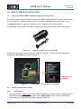
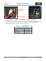
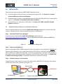
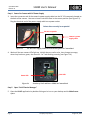
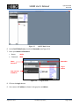
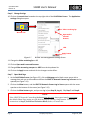
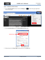
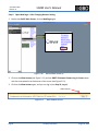
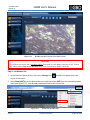
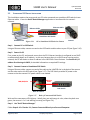
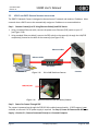
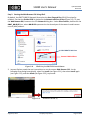
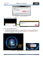
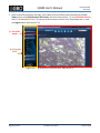
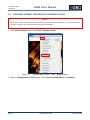
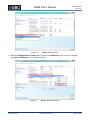

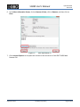
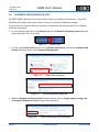
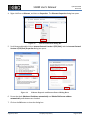
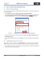
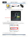
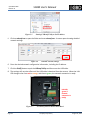
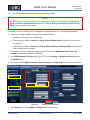
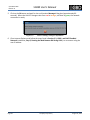
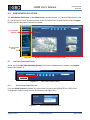
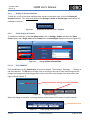
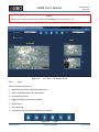
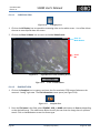
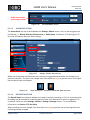
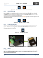

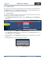
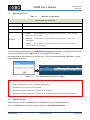
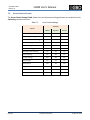
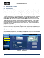
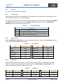
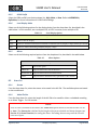
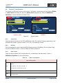
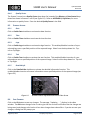
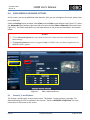

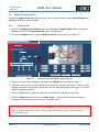
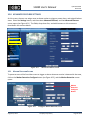
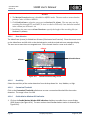
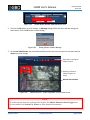

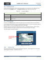
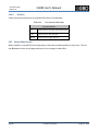
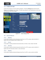
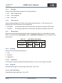
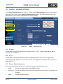

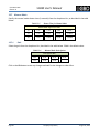
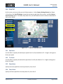

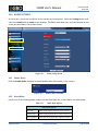
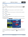

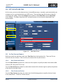
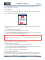
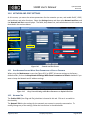

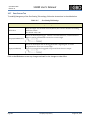
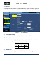
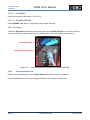
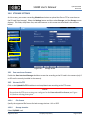
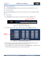
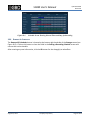
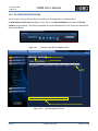
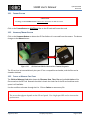
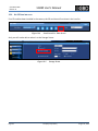
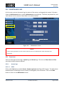
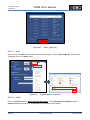
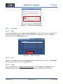
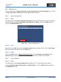
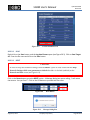

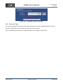
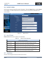

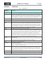
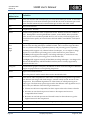
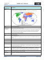


![FLM HD18 [v08]](http://vs1.manualzilla.com/store/data/005664321_1-9e0d84f2b9cac33a4ebfb5904f0dafa1-150x150.png)