1
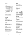
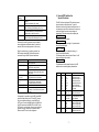
MIF3
midi time code
interface
TABLE OF CONTENTS
1
Front Panel
2
2
Back Panel
3
3
Unit Operation
4
I. LTC and MTC Generation from MTC
II. LTC and MTC Generation from LTC
III. MMC Controlled LTC and MTC
Generator
4
5
5
Internal DIP Switches for
Special Functions
7
I. DIP 1-3, Midi Cue Mode
8
II. DIP 4, Hold Off Value
III. DIP 5, Calibration Display
IV. DIP 6-7, Electronic Gear Box
V. DIP 8, Default Standard
9
9
9
9
user manual
4
5
14
Specifications
10
-1-
(7) Mode Switch
Switches between the three operation modes:
„mtc“ (MTC input, LTC and MTC generation)
„generate“ (MMC input, LTC and MTC generation)
„ltc“ (LTC input, LTC and MTC generation)
1 Front Panel
(8) „ltc level“
The „ltc level“ potentiometer allows you to adjust the
LTC output level from 0-3 Vpp.
2
Back Panel
(1) LED display
The display shows incoming and generated time code
as well as calibration status, locked status and the
internal dip switch settings. In this manual all display
messages are represented in this style:
8.8.8.8.8.8.8.8.
(2) „on“ Switch
Turns the power to the MIF3 on and off.
Each time the MIF3 is powered up, it runs through the
display test, shows the software version and the internal
dip switch settings.
(3) „on“ indicator
Indicates proper function of the built-in power supply.
(4) „24“ Indicator
Indicates correct receiving of 24 fps MTC or LTC time
code as well as generation of 24 fps time code.
(5) „25“ Indicator
Indicates correct receiving of 25 fps MTC or LTC time
code as well as generation of 25 fps time code.
(6) „30“ Indicator
Indicates correct receiving of 30 fps MTC or LTC time
code as well as generation of 30 fps time code.
29,97 and 30 fps drop frame time code are indicated by
simultaneous lightning of indicators „25“ and „30“.
-2-
(9) „MIDI IN“ Connector
This 5-pin DIN connector accepts an MTC and MMC
Midi signal. For reliable operation use only shielded MIDI
cables.
(10) „LTC input“ Connector
This RCA connector accepts an unbalanced LTC time
code signal. The input circuit exhibits a wide range of
sensitivity: -40 to +20 dBu. This allows reliable operation
of the unit also with low level LTC sources.
(11) „LTC output“ Connector
This RCA connector outputs unbalanced LTC time code.
The output level can be adjusted with the „ltc level“
potentiometer at the front panel. The MIF3 outputs
running time code at play speed as well as positional
time code for cueing and locating.
(12) „MIDI OUT“ Connector
This 5-pin DIN connector outputs Midi Time Code
(MTC). The MTC signal can be applied to any MIDI
interface. For reliable operation use only shielded MIDI
cables.
(13) VAC input
Use the provided AC power cord to connect the MIF3 to
the AC power supply through this connector.
-3-
3
The „locked indicator“ shows you proper synchronized
time code regeneration also at non-nominal master time
code speed.
Unit Operation
I. LTC and MTC Generation from MTC
Set the mode switch (7) to positon „mtc“ and connect an
MTC source to the „MIDI IN“ connector (9). The MIF3
shows the incoming MTC on the LED display and the
used time code standard according to the three time
code standard indicators (4), (5), (6).
If the incoming MTC runs at nominal play speed (100%),
the MIF3 will start synchronized LTC and MTC
regeneration immediately (typically after 4 frames).
This „locked“ regeneration status is indicated on the LED
display by the last decimal point.
.
This decimal point segment is called the „locked
indicator“ in this manual.
Rosendahl sync algorithms supress time code jitter and
drop outs to allow the use of unstable, jittery MTC
sources produced by most PC and MAC based audio
workstations.
If the incoming MTC does not run at nominal play speed,
the MIF3 starts the calibration procedure.
Then the display changes from the time code mode into
the calibtation mode and shows the current calibration
factor related to nominal play speed.
Cb
When the MIF3 is receiving a MTC Full Message as well
as an MMC locate command it will stop the time code
generator and generate a positional LTC and MIDI
message according to the selected MIDI cue mode.
II. LTC and MTC Generation from LTC
Set the „Mode Switch“ (7) to positon „ltc“ and connect
the master LTC source to the „LTC input“ connector
(10). The MIF3 shows the incoming LTC on the LED
display and the used time code standard according to
the three time code standard indicators (4),(5),(6).
If the incoming LTC runs at +-10% of nominal play
speed the MIF3 will start synchronized LTC and MTC
regeneration immediately (typically after 4 frames).
This locked regeneration is indicated by the locked
indicator.
If the incoming LTC is running slower or faster than +10% of nominal play speed, or is running reverse, or is
positional time code, the MIF3 stops the time code
generator and generates a positional LTC and MTC
burst according to the selected MIDI cue mode.
III. MMC Controlled LTC and MTC
Generator
1. 00 00
The calibration procedure will take some seconds while
the display is indicating the current calibration factor. If
the display changes back into the time code mode the
calibration procedure is done.
Do not stop the master time code as long as the
calibration procedure has not been finished.
The time code generator is started by switching the
mode switch to position „generate“.
It depends on the status of the synchronizer, when you
are switching to the generator mode, how the following
time code generation will be performed.
If you stop and restart the „non-nominal speed“ MTC
again, the MIF3 starts now synchronized LTC and MTC
regeneration immediately with the new „learned“ nonnominal speed. Once the non-nominal speed has been
calibrated, the unit works as fast as you are used from
working at nominal play speed.
-4-
-5-
Status when
switching
Generator mode
mtc, unlocked
generates from last read mtc value and time code
standard
with nominal Calibration (Cb 1.0000)
keeps on generating running time code,
holds and shows actual Calibration (Cb x.xx xx)
starts generating TC from 59:40:00:00
at nominal Calibration (Cb 1.0000) with default
standard 25fps or 30fps (dip switch 8)
keeps on generating running time code,
holds and shows actual Calibration (Cb x.xx xx)
mtc, locked
ltc, unlocked
ltc, locked
Whenever you switch to generator mode, the display
shows the generator calibration window for about two
seconds. But the time code generator is still running.
When the mode switch is in position „generate“, the
MIF3 accepts several MMC (midi machine control)
commands through its MIDI input as listed below:
Command
Description
F0 7F 7F 06 01 F7
MMC „stop“
stops the generator
MMC „play“
starts the time code generator
MMC „deferred play“
starts the time code generater after active
MCP (locate)
MMC „locate“
sets generator to time code position
MMC „write time standard“
sets generator time code standard
at nominal Calibration (CB 1.0000)
MMC „reset“
Rosendahl exclusive „dip switch“
dd sets dip1-7 soft until the unit is powered
up again.
F0 7F 7F 06 02 F7
F0 7F 7F 06 03 F7
F0 7F 7F 06 44 06 01 hr
mn sc fr ff F7
F0 7F 7F 06 40 03 45
01 tt F7
F0 7F 7F 06 0D F7
F0 2C 7F dd F7
Consequently it is possible to use the MIF3 as an MMC
controlled virtual machine with LTC and MTC outputs.
Set your workstation software to „output MMC“ and
„MTC slave“. Connect the MMC output to the MIDI IN of
the MIF3 and connect the MIDI OUT of the MIF3 to the
MTC input of your workstation. Now you can remote the
generator from your sequencer or workstation which
follows as an MTC slave in this configuration.
-6-
4
Internal DIP Switches for
Special Functions
The MIF3 unit has eight internal DIP switches to preset
the synchronizer to special functions. To get the
information how these eight internal swiches are set, it is
not necessary to open the box, because in the power up
routine the display shows the current settings as
abbreviations.The routine starts with the display test
8.8.8.8.8.8.8.8.
and shows the firmware version
SoFt
3.10
followed by the midi cue mode (dip 1-3) and the default
time code standard (dip 8).
FuLL
25
If the gear box (dip 6-7) is enabled the letter „g“ is
in front of the default standard.
The following window shows the hold off value: 5 or 50
frames, according to dip switch 4.
Hoff
5
The table below lists the special functions of the DIP
switches and the according display abbreviations:
DIP-No.
Settings
Abbreviation.
0-0-0
1-0-0
0-1-0
1-1-0
0-0-1
1-0-1
1-1-1
0
1
q.L.
q.L.-2
q.b.
q.b.-2
FuLL
Loc
oFF
Hoff
5
Hoff 50
0
1
0-0
1-0
0-1
1-1
0
1
hr.mn.sc.fr
Cb x.xxxx
25, 30
g25
g24
g30
25
30
1-2-3
4
5
6-7
8
-7-
Function
midi cue mode
quarter frame loops
quarter frame loops -2
quarter frame bursts
quarter frame bursts-2
MTC Full Message
MMC locate command
no output
Hold off = 5 frames
Hold off = 50 frames
LED Display mode
TC and Calibration (auto)
only Calibration
electronic gear box off
gear box 25 fps output
gear box 24 fps output
gear box 30 fps output
default standard 25 fps
default standard 30 fps
I. DIP 1-3, Midi Cue Mode
II. DIP 4, Hold Off Value
Midi Time Code is the standard used to translate
SMPTE time code into MIDI messages. There are two
basic types of messages, described as Quarter Frame
and Full message. The Quarter Frame message is used
for normal running status at play speed. The Full
message communicates a specific time for locating or
cueing.
Most digital audio workstations can be synchronised with
MTC midi time code to perform a trigger start of the
playback function in combination with an external video
or word clock reference to hold the system in continious
sync. Master time code (e.g. from analog tape
machines) which ramps up and down can cause a
continious offset error because the MTC trigger start has
been executed to early.
The hold off value defines the number of passed frames
until the MTC signal is output when the MIF3 is locked to
the external time code source. A hold off value of 50
frames (dip 4 = on) will delay the synchronisation
process for 2 seconds, but also prevents „too fast“ MTC
trigger starts.
Unfortunately many devices which are using MTC do not
have implemented the Full message.
For that reason the MIF3 supports some other midi cue
modes for locating or cueing your sequencer / audio
workstation frame accurately to a master time code. One
of these methods to cue up a DAW is the use of the
MMC „Locate“ command, if the slaved DAW supports
MMC slave mode together with MTC slave mode.
Therefore set the midi cue mode to Locate. (for example
with Digidesign ProTools 4.2, Roland VS-880, Fostex
FD8...) Then the MIF3 outputs an MMC locate command
instead of the Full message.
Other recording software can be located by a loop or a
burst of several quarter frames. The Creamware Triple
DAT Software, for example, works fine with the midi cue
mode q.b.-2.
Because the MIF3 MIDI input accepts all these different
cue modes and the MIDI output can output any midi cue
mode the MIF3 is able to interface a Full message, for
example, into a MMC locate command.
The match on the LTC side is called positional time
code. This is a continuous loop of one frame for cueing
or locating. The MIF3 detects positional time code and
translates the positional frame into the selected midi cue
mode message. CB electronics SR-4, FEG v-mod or
Doremi V1, for example do produce positional LTC.
The MIF3 also translates incoming MTC Full messages,
MMC Locate commands or Quarter Loops into positional
LTC.
III. DIP 5, Calibration Display
DIP switch 5 causes the display to show always the
calibration factor.
Cb 1. 00 00
This allows you to use the MIF3 as an LTC and MTC
speed meter with 100 ppm resolution. All other functions
of the MIF3 synchronizer remain working.
IV. DIP 6-7, Electronic Gear Box
The electronic gear box performs time code standard
conversion. If the 24 fps gear box function, for example,
is enabled, the MIF3 will read any incoming time code
standard (24, 25, 30 fps) and regenerate synchronized
24 fps time code.
Note: Drop frame standards are not supported by the
electronic gear box!
The time code standard indicator of the incoming time
code is lighting continuously and the indicator of the
generated time code standard is flashing each „zero“
frame. The gear box can be used to transfer Film to
Video time code and vice versa. The „locked“ indicator is
still indicating proper synchronization.
V. DIP 8, Default Standard
The default standard setting defines the time code
standard when the unit is powered up and also the
preset standard for the generator mode „ltc, unlocked“.
-8-
-9-
5
Specifications
LTC input
RCA female -40! to 20 dBu, 10k ohms
0,5 to 200% of playspeed, reverse and positional,
format auto-detection (24, 25, 30 drop, 30 fps)
LTC output
RCA female 0-3 Vpp adjustable, 500 ohms
positional time code output for cueing
(24, 25, 30 drop, 30 fps)
MIDI input
5-pin DIN, The Complete MIDI 1.0
MTC quarter frame and full messages
MMC stop, play, defplay, locate, write standard field,
Rosendahl system exclusive
MIDI output
5-pin DIN, The Complete MIDI 1.0
MTC quarter frame and full messages
MTC quarter loops, MMC locate
Power
Euro EN 60.320, 230 VAC, 50 Hz, 30 mA
115 VAC, 60 Hz, 60 mA (US-version)
LED Display
8 x HP 7503, 6mm (0,3“) red
Dimensions
11,4 cm W x 3,1 cm H x 16,8 cm D,
1U-19“ rackmount kit available
Declaration of Conformity
Rosendahl Studiotechnik GmbH
Isoldenstraße 26
D-80804 München
herewith confirm that the product:
Type:
Audio and Video Sync Generator
Model:
Nanosyncs
meets the requirements of the council of the European communities
relating to electromagnetic compatibility (Council Directive
89/336/EEC)
Technical Data:
CENELEC EN 50 081-1
CENELEC EN 50 082-1
The CE symbol is awarded to high-quality appliances which comply
with the European Directive 89/336/EEC or the EMVG (law relating
to electromagnetic compatibility of appliances) and which offer the
following significant benefits:
*Simultaneous and interference-free operation of adjoining
appliances
*No unpermitted interference signals
*High resistance to electro-smog
Weight
0,7 kg
- 10 -
1/1992
1/1992
- 11 -