1
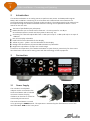
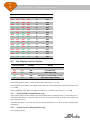
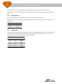
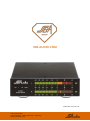
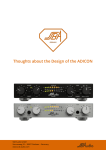
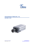
Audio Level Meter Connecting and Operating SSB Audio GmbH Sonnenweg 25 – 30827 Garbsen – Germany www.ssb-audio.com Page 1 Audio Level Meter – Connecting and Operating Contents 1 SAFETY GUIDELINES – READ BEFORE USING! ................................................................................. 2 2 Introduction ........................................................................................................................................ 3 3 Connection .......................................................................................................................................... 3 3.1 Power Supply ........................................................................................................................... 3 3.2 Line Input/Output.................................................................................................................... 4 4 Settings ................................................................................................................................................ 4 4.1 PPM and VU Mode Selection ................................................................................................. 4 4.2 Input Sensitivity ....................................................................................................................... 4 4.3 Bar Display and Dot Display .................................................................................................. 5 4.3.1 Peak Hold (Bar Display Mode only) ....................................................................................... 5 4.3.2 Yellow Dot (Dot Display Mode only) ..................................................................................... 5 4.4 Background .............................................................................................................................. 6 4.5 Brightness ................................................................................................................................ 6 5 Technical Data .................................................................................................................................... 7 5.1 Measurements ......................................................................................................................... 7 5.2 Connections ............................................................................................................................. 7 5.2.1 Inputs ........................................................................................................................................ 7 5.3 Power Supply ........................................................................................................................... 7 5.4 Housing ..................................................................................................................................... 7 Page 2 1 Audio Level Meter – Connecting and Operating SAFETY GUIDELINES – READ BEFORE USING! The device meets protection class 2 and has left the factory in a technically faultless state. In order to assure this state and to insure riskless operation the user must obey the notes and warnings which are part of this manual. SAFETY, RELIABILITY AND PERFORMANCE OF THIS DEVICE ARE GUARANTEED ONLY WHEN: Installation, expansions, modifications and repairs are accomplished only by the manufacturer or by personal authorized by the manufacturer. The electrical installations of the relevant room meet the corresponding IEC (ANSI) requirements. The device is used in accordance with this user manual. POWER SUPPLY The device is designed for continuous operation. The power supply’s operating voltage must meet the local line voltage. Avoid connections to the power supply system in junction boxes together with many other devices. The electrical outlet needs to be installed close to the device and easily accessible. Use the supplied power supply unit. Other power supplies may cause malfunctions or even damage the device. INSTALLATION SITE The device should stand only on clean horizontal work surfaces or be installed in a suitable rack. During operation the device must not be exposed to vibration. Humidity, liquids of all kinds and dust must be kept away as far as possible. Sufficient ventilation needs to be provided. Avoid direct sunshine and the proximity of radiators and radiant heaters. Page 3 Audio Level Meter – Connecting and Operating 2 Introduction This Audio Level Meter is an analog stereo VU (Volume Unit) meter and PPM (Peak Program Meter) with 2 LED bars containing 51 bi-color LEDs each. PPM and VU measurements are performed widely meeting the according studio standards. The analog signals to be metered can be looped through the Audio Level Meter. Different settings can be performed with a 10-fold switch on the rear side. Two sets of paralleled input jacks (RCA) PPM evaluation (10 ms attack time to 90% and 1.5 s decay time for -20 dB) or VU evaluation (300 ms attack and decay time to 99% resp. 1%) Sensitivity for 0 dB scale adjustable from +5 dBu (1377 mV) to -10 dBu (245 mV) in 16 steps of 1 dB each Dot or bar display selectable Peak hold function selectable for bar display Yellow or green - yellow - red dot selectable for dot display Background illumination (all passive LEDs dimmed on) selectable Brightness adjustable in 4 steps over a wide range Connection and operation of the Audio Level Meter is quite obvious, particularly for those users who have been concerned for many years with the technology of their equipment. 3 Connection 3.1 Power Supply The included 12-volt power adapter can be connected to the Audio Level Meter with a lockable connector. Rotate the plug clockwise so that that it cannot be accidentally disconnected. The Audio Level Meter is turned on by pressing the POWER switch. The operation is indicated by the illumination of one of the two LEDs VU or PPM on the front panel. Page 4 Audio Level Meter – Connecting and Operating 3.2 Line Input/Output The audio signals can be connected to any of both RCA stereo jack pairs and looped to another device through the other RCA stereo jack pair. They ought to have a level between -10 dBu (245 mV) and +5 dBu (1377 mV) for a reading of 0 dB and they are loaded very weakly by 133 kΩ only. 4 Settings 4.1 PPM and VU Mode Selection Switch 1 Mode OFF PPM ON VU The selected mode is also indicated on the front panel. Some background information about VU and PPM measurements: In both modes, a constant sine wave tone is indicated with the same level. But as soon as it is no constant sine wave any more, the measured values in both modes are very different. For VU meters the ballistic characteristic is specified as follows: The attack time is 300 ms for a value of 99% of the final value with a succeeding overshoot of 1 to 1.5%. The decay behavior is identical. Thus VU measurements are quite slow and do not respond quickly to peaks in the signal. VU measurements were in early times used in broadcast studios. Also in HiFi equipment the meters are called VU meters, but usually do not feature the specified ballistic behaviors. The PPM attack time is specified as 10 ms for a value of 90% of the final value. This is quite fast, much faster than VU. For good reasons the decay behavior is completely different: It is specified as -20 dB in 1.5 seconds. Otherwise the level of a short peak would be invisible. PPMs were introduced much later and due to their much better responsitivity, they displaced the VU meters in studios completely. In practice, for real audio programs, measured PPM values are a couple of dB higher than those of VU meters. In the Audio Level Meter for both modes the specified ballistic characteristics are precisely met. For the scale a compromise is chosen in order to achieve a common scale for both modes: VU meters shall have a linear scale ranging from approx. -20 dB to +3 dB while the scales of PPMs are logarithmic and, moreover, scale ranges are internationally differently standardized. As the Audio Level Meter can work in both modes the compromise is that the scale for both modes is logarithmic and reaches from -31 dB to +5.5 dB. 4.2 Input Sensitivity The input sensitivity for a reading of 0 dB can be adjusted in 16 steps of 1 dB each from -10 dBu (245 mV) to +5 dBu (1377 mV): Page 5 Audio Level Meter – Connecting and Operating Switch Position Sensitivity for 0 dB 2 3 4 5 dBu mV OFF OFF OFF OFF +5 1377 ON OFF OFF OFF +4 1228 OFF ON OFF OFF +3 1094 ON ON OFF OFF +2 975 OFF OFF ON OFF +1 869 ON OFF ON OFF 0 775 OFF ON ON OFF -1 690 ON ON ON ON -2 615 OFF OFF OFF ON -3 548 ON OFF OFF ON -4 489 OFF ON OFF ON -5 436 ON ON OFF ON -6 388 OFF OFF ON ON -7 346 ON OFF ON ON -8 308 OFF ON ON ON -9 275 ON ON ON ON -10 245 4.3 Bar Display and Dot Display Switch Position Display Option 6 7 OFF OFF Bar No Peak Hold OFF ON Bar With Peak Hold ON OFF Dot Dot Color Corresponding to Value ON ON Dot Dot Color Always Yellow In bar display mode, when no LED is illuminated, the level is < -31 dB. In dot display mode always one LED is illuminated, thus the leftmost LED indicates that the level is < -30 dB. In both display modes, when the rightmost LED is lit, it means that the level is > +5.5 dB. 4.3.1 Peak Hold (Bar Display Mode only) Often a peak hold function where a measured peak value is displayed over a certain time by an illuminated LED proves to be useful. Because you do not have to look so closely, short peaks can be recognized easier. The peak hold time is 1 second and can be enabled with switch 7 on when the bar display mode is activated. 4.3.2 Yellow Dot (Dot Display Mode only) In dot display mode: Page 6 Audio Level Meter – Connecting and Operating When switch 7 is on, the dot appears in yellow independent of its position on the scale. When switch 7 is off, the dot appears either in green, yellow or red depending on the measured value. 4.4 Background Without background only the LEDs for the measured values are illuminated. With background all other LEDs are illuminated weakly, too, so that the full scale is visible even in darkness. Switch 8 Background OFF Off ON On 4.5 Brightness The LEDs can be adapted in their brightness to the user’s individual preferences in 4 relatively big steps so that even in very bright environments the display is clearly readable or, vice versa, in very dark environments the display will not be annoying. Switch Position Brightness 9 10 OFF OFF 100% ON OFF 25% OFF ON 6% ON ON 1.5% Page 7 5 Audio Level Meter – Connecting and Operating Technical Data (Errors and technical modification subject to change) 5.1 Measurements PPM 10 ms attack time to 90%, 1.5 s decay time for -20 dB VU 300 ms attack and decay time to 99% resp. 1%, 1.25% over- and undershoot Scale Logarithmic, -31 dB to +5.5 dB Sensitivity Adjustable from +5 dBu (1377 mV) to -10 dBu (245 mV) for 0 dB scale display 5.2 Connections 5.2.1 Inputs LINE I/O Two pairs of RCA jacks, paralleled for loop-through of stereo signals Impedance 133 kΩ Max. input voltage 10 VPP for undistorted measurements 5.3 Power Supply Connector: Low-voltage connector (barrel jack) 5.5/2.1 mm, lockable Operating voltage: 12 VDC Current consumption: Less than 1.5 A 5.4 Housing Material: Steel, powder-coated surface, front panel 5 mm aluminum Dimensions: Depth: Width: Height: Height: Weight: Audio Level Meter: Power supply: 172 mm 140 mm 40 mm 50 mm 875 g 160 g without connectors without stands with stands SSB-AUDIO.COM SSB-Audio, 2015-07-26 SSB Audio GmbH Sonnenweg 25 – 30827 Garbsen – Germany www.ssb-audio.com