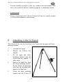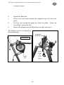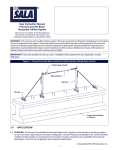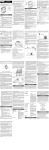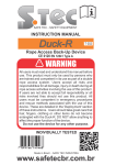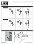
1
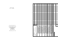
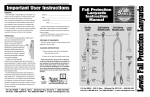
USER INSTRUCTION MANUAL G-SAVER II Retractable Fall Arrest Lifeline & Retrieval System EN 360 EN 1496: Class B GLOBESTOCK MILE OAK INDUSTRIAL ESTATE, MAESBURY ROAD, OSWESTRY, SHROPSHIRE SY10 8GA TEL: 01691 654966 FAX: 01691 661726 EXAMINATION RECORD Notified Body No: 0120 SERVICE DUE NEXT Cable locks when pulled sharply Cable extracts fully Cable retracts fully Cable No broken strands or kinks Free of severe corrosion Eyelet / Thimble present Karabiner Gate functions freely Swivel action operates Free of damage & corrosion Case / Free of damage & cracks Housing Fasteners present & secure Labels present & Legible Rescue Engages / Disengages Mechanisms Winds down & up Function Smooth, firm operation Rescue pull & twist to lock out Mechanisms Holds winch arm in engagement locking trigger No damage/satisfactory operation General No Damage / Severe Corrosion Condition Fasteners present & secure Additional Points: EC Type Examination by: Function Date First Used: Serial No: Manufacture Date: SIGN DATE SGS United Kingdom Ltd. Weston-Super-Mare BS22 6WA United Kingdom G-SAVER II, 407 to 434 Series. Issue No: 006 Date: 30.6.2005 The G-Saver II Retractable Fall Arrest Lifeline & Retrieval System USER INSTRUCTION MANUAL Contents Page 1. Important Notice 1 2. G-Saver II Fall Arrest & Retrieval Device 2 3. Before Use Checks 3 4. Installation 4 4.1 Anchorage Points / Devices 5 4.2 Connectors 5 4.3 Attaching the User 5 5. Instructions for Use 6 6. Assessing the Working Environment 7 6.1 Fall Arrester Anchored Vertically Overhead 7 6.2 Fall Arrester Anchored Horizontally 8 6.3 G-Tripod Anchorage for Confined Space work 10 7. Retrieving the User after a Fall 11 8. Inspection & Maintenance 12 8.1 Periodic Examination 12 8.2 Service & Re-Certification 12 8.3 Cleaning, Storage and Transportation 12 9. Attaching to the G-Tripod 13 -0- The G-Saver II Retractable Fall Arrest Lifeline & Retrieval System 1. IMPORTANT NOTICE READ EQUIPMENT LABELS AND USER INSTRUCTION MANUAL BEFORE USE. BEFORE USING THIS EQUIPMENT IT IS ESSENTIAL THAT USERS ARE FULLY AWARE OF HOW TO OPERATE THE EQUIPMENT, WHERE IT SHOULD BE USED, WITH A PREDETERMINED ACTION PLAN FOR BOTH THE USE AND RECOVERY SHOULD A FALL OCCUR. These products have been produced to reduce the risk of injury or death occurring as a result of a fall. INCORRECT USE could lead to SERIOUS or FATAL INJURY. Only one person should be attached to the G-Saver II. The equipment user should never be left to work on their own. There must always be another person present to initiate the chosen method of retrieving the user should a fall occur. The safe use and method of retrieving the user after a fall, must be determined during Risk Assessment. PRIOR TO USE: The appropriate ‘Risk Assessments’ should be carried out, considering use and emergency rescue procedure. Users should be fully conversant with the operation of the equipment. The ‘Before Use Checks’ should be performed (see section 3 and the Front Label). -1- The G-Saver II Retractable Fall Arrest Lifeline & Retrieval System 2. G-Saver II Fall Arrest & Retrieval Device The G-Saver II has a tough aluminium housing. Internal components are manufactured from aluminium alloys, stainless steel, steel, bronze, and plastics. Shackle Crank Arm Safety Hook / Karabiner The G-Saver II’s anchorage shackle must be attached to a suitable anchorage that meets the strength requirements (see section 4.1) and positioned so as to minimise the fall distance. The G-Saver II must be used in conjunction with a Full Body Harness. The lifelines safety hook must be fitted to the attachment point of the full body harness. The G-Saver II should be used with the retrieval mechanism disengaged. The lifeline is spring tensioned so that it extracts and retracts from the unit, ensuring that there is no slack rope. This enables the user to move freely while helping to keep the potential fall distance to a minimum. In the event of a fall, rope is pulled out of the unit at an accelerating rate. On reaching the activation speed of approximately 1.5m/s, the braking mechanism will engage. The energy of the fall is dissipated and the user brought to a halt. There must be adequate clearance below the user to safely stop a fall. See sections 6 to 6.2. Once a fall has been arrested, the user remains suspended until rescued to a safe platform or the ground. The crank arm can be engaged to raise or lower a person. To lower a person after a fall, the crank arm must first be ‘Raised’ half a turn to release the fall arrest brake. Once the brake is released, the operator may lower or raise to retrieve the user. -2- The G-Saver II Retractable Fall Arrest Lifeline & Retrieval System 3. Before Use Checks Inspection Inspect the fall arrest system for any signs of damage, wear or malfunction. The rope should be extracted from, and allowed to retract back into the fall arrest unit as it is being inspected. The rope should freely return into the unit with no obstructions such as kinks, excessive build-up of dirt or other fouling preventing retraction. Check the safety hook and it’s gate locking function. Test Test the Fall Arrest Function With the retrieval arm disengaged, test the fall arrest function by pulling sharply on the safety hook. The unit’s brake must lock positively, and remain locked until released. Test the Retrieval Mechanism 1. Pull out/up and hold locking trigger ring. Push crank arm into body to engage mechanism. Align gears if necessary by slight rotation of Crank Arm. 2. Release locking trigger ring. Ensure it seats within the slot. 3. Attempt to pull crank arm away from the body of the unit to check gearing is locked in position. 4. Rotate Crank Arm. 5. Lift up locking trigger ring, pull out Crank Arm and release locking trigger ring to disengage mechanism. -3- Crank Arm Locking Trigger Ring The G-Saver II Retractable Fall Arrest Lifeline & Retrieval System 4. Installation Connect the G-Saver II to an anchor point by it’s shackle. The fall arrest brake mechanism will activate in any orientation. When used lying ‘Crank Arm’ down some premature activation may occasionally be experienced. Following are some examples of installation configurations. The G-Saver II can be used; a) b) mounted vertically overhead. with a diverter pulley to provide safe overhead fall protection and provision for rescue. for roofing applications in conjunction with a suitable roof anchor, where determined appropriate by a formal risk assessment. (Section 6.2.) mounted on a temporary anchorage device, such as the G-Tripod, for protection in confined space applications. (Section 6.3 & 9) c) d) a) b) The anchorage for the G-Saver II should be positioned so as to: 1. 2. Minimise the fall distance. Avoid any obstacles. Fall away from, rather than into, any obstacles that may harm the user. -4- The G-Saver II Retractable Fall Arrest Lifeline & Retrieval System 4.1 Anchorage Requirements 4.2 Connectors 4.3 Anchorages to EN 795 may be used. Anchor points must have a minimum static strength of 1225kg (12kN) per attached G-Saver II. Connectors used with the GSaver II should be to EN 362 or equivalent. Metal connectors must have a minimum strength of 1530kg (15kN), in the direction of loading. Webbing products or non-metallic connectors must have a minimum strength of 2240kg (22kN). These must not be used in contact with sharp edges or rough abrasive surfaces that may cause damage. Lanyards must not be used to extend the length of the wire rope. Where deemed suitable by the harness manufacturer, a short strap (0.5m maximum length) may be fitted, to extend the attachment point of the full body harness allowing easier connection of the safety hook. Attaching to the User The User must wear a Full Body Harness that meets the requirements of EN361. Connect the G-Saver II’s Safety Hook Karabiner directly to the fall arrest attachment point of the Harness. Ensure that the gate is closed and locked. -5- The G-Saver II Retractable Fall Arrest Lifeline & Retrieval System 5. Instructions for Use Should any doubt arise about the safe condition of this device - DO NOT USE. Return to manufacturer or a manufacturer authorised servicing agency for attention. Protect your hands when inspecting or handling the wire rope. A rescue plan must be in place and ready to be implemented should a fall occur. Never use as a restraint or positioning device For protecting one user only, as a fall arrester, when attached to that user’s full body harness attachment point. Never use the fall arrester for protection on or above unstable materials such as grain mounds, powders etc. where the user runs the risk of slowly sinking into the material, below the fall arrest brake activation speed. The retractable fall arrester may only be used by a trained and/or otherwise competent person or the user should be under the direct supervision of such a person. The Retractable Fall Arrester should only be used or subjected to temperatures within the range of 50˚ to -30˚ centigrade. Always position the anchorage or choose an anchorage point that minimises the fall distance. Ensure there is enough clearance below the work area to safely arrest a fall. The user’s potential fall path should be free of obstructions that could cause injury, or limit the fall to below the fall arrest brake activation speed. Does fall protection necessitate the use of further Personal Protective Equipment such as Helmets, knee pads, gloves etc. for that environment. When the rope is extended do not release and allow the wire rope to run freely back into the device. Never cross another person’s lifeline Never allow the rope to pass under or get wrapped around a person, their arms or legs. When working never allow the rope to become slack, never clamp off or stand on the wire rope. Do not allow the rope to pass over sharp edges, electrical items/cables, become frayed or to kink as this weakens the rope. Be aware of any medical condition that may affect the safety of the equipment user in normal and emergency use. If there is any doubt seek medical advice or do not use the equipment. -6- The G-Saver II Retractable Fall Arrest Lifeline & Retrieval System 6. Assessing The Working Environment For use in any requirement for working at height, that demands mobility over a large working area. The fitness for purpose must be verified by formal risk assessments. These notes are for guidance purposes only. It is essential that a person who is trained or otherwise competent to do so, assesses applications. An assessment to determine the safe use and emergency retrieval plan should only be carried out after reading this manual. Each application may be different. These instructions are produced as a guide only. They can never replace the requirement for a formal assessment of each application by a suitably competent person. A plan of work and emergency rescue procedure must be in place. The work / emergency rescue procedures must be continually considered to suit any changes in the working environment. 6.1 Fall Arrester Anchored Vertically Overhead Working with the fall arrester anchored vertically overhead is the ideal arrangement for use as the potential fall distance is kept to a minimum. There must always be adequate clearance below the working area to allow a fall to be stopped safely. Allow 2 metres plus the Height of the User, for clearance below the working area. See figure 1. Be aware of any form of obstruction that may injure the user should a fall occur. Implement measures to remove any risk. -7- The G-Saver II Retractable Fall Arrest Lifeline & Retrieval System Where there is the possibility of a swing fall occurring: Additional clearance below is required if working out from underneath the fall arrester. See figure 2. Beware of swinging into obstructions. Figure 1. – Clearance Below Figure 2. –Additional Swing Clearance 6.2 Fall Arrester Anchored Horizontally The fall arrest brake mechanism will operate with the unit mounted in any orientation. There must be adequate clearance below the working area to stop a fall safely. See figure 3. Be aware of working sideways out from the fall arrester. Additional clearance is required where there may be a swinging fall. Figure 3. -8- The G-Saver II Retractable Fall Arrest Lifeline & Retrieval System In the event of a fall, the rope must not pass over; sharp or abrasive edges. masonry or steelwork. electrical wires or components that may harm the user. Anything that may catch, trap or shear the wire rope. The User could be in MORTAL DANGER if the above points are ignored. The anchorage must be situated so as to minimise the potential fall distance, taking special notice of swing falls. See figure 4. Should the user fall, the brake mechanism will activate at an approximate speed of 1.5 m/s. If the fall does not reach this speed then the brake may not activate. Figure 4 – Anchorage to minimise Swing Fall. Figure 5 – Anchorage to minimise Fall Distance. -9- The G-Saver II Retractable Fall Arrest Lifeline & Retrieval System 6.3 G-Tripod Anchorage for Confined Space Work The G-Saver II may be used with the G-Tripod for protection when entering or working in confined spaces. See section 9 for set-up instructions. There must always be someone ‘top-side’ to operate the G-Saver II and retrieve the user in an emergency or after a fall. Training is essential for those involved with confined spaces work. Figure 6 – Confined Space Entry Figure 7 – Retrieving a User. - 10 - The G-Saver II Retractable Fall Arrest Lifeline & Retrieval System 7. Retrieving the User After a Fall Once a fall has been arrested, the user will remain suspended until rescued to a safe platform or the ground. It is important that the rescue procedure is carried out quickly after a fall. In order to release the fall arrest brake mechanism, the suspended person must be raised, allowing the rope to retract a little way into the G-Saver II. The rope can then extract from the unit, allowing the user to be rescued to a safe place. The retrieval destination and the manner of retrieval must be determined during a pre-use assessment. The user must not be left suspended for extended periods of time. The G-Saver II’s retrieval mechanism may be engaged to retrieve the user. Instructions to Engage the Retrieval Mechanism are also situated on the rear label. 1. Pull out/up and hold locking trigger ring. Push crank arm into body to engage mechanism. Align gears if necessary by slight rotation of Crank Arm. 2. Release locking trigger ring. Ensure it seats within the slot. 3. Attempt to pull crank arm away from the body of the unit to check gearing is locked in position. 4. Rotate Crank Arm up half a turn to disengage Fall Arrest brake. 5. The User can now be Raised or Lowered to safety. - 11 - The G-Saver II Retractable Fall Arrest Lifeline & Retrieval System 8. Inspection & Maintenance Like all complex mechanical safety devices, the G-Saver II requires regular inspection and maintenance to ensure that the unit functions correctly. Repairs or servicing should never be carried out on site or in the field. Do not tamper with or modify the unit. 8.1 Periodic Examination. The G-Saver II should be periodically examined by a competent person, other than those using the equipment, at least once in every 6 months dependant upon the frequency of use and the operating environment. The ‘Examination Record’ found on the rear of this manual, outlines the main examination criteria. On passing this examination the record can be completed, signed off and the unit returned for use. Any observed faults must be rectified. If necessary, return the G-Saver II for service and re-certification. 8.2 Service & Re-Certification. The G-Saver II must be returned for servicing annually and in the event of a fall arrest. Only a Globestock approved servicing agency can be used for this. On completion of a service and retest, a new Test Certificate will be issued which validates the unit for a further year of use. 8.3 Cleaning, Storage and Transportation The G-Saver II’s exterior may be cleaned using warm water with a mild detergent. It should then be hung, by it anchorage shackle, to dry in a warm environment. In order to maintain the wire rope, extract the rope from the unit, removing any soiling. Apply a little light oil to a cloth. Hold the cloth around the rope, allowing the rope to slowly retract back into the unit. This will leave the rope lightly oiled, while ensuring the internal mechanism is not oil contaminated. - 12 - The G-Saver II Retractable Fall Arrest Lifeline & Retrieval System The unit should be stored in a clean, dry, chemical free environment. The unit is best stored off the floor, ideally hanging by it’s anchorage shackle. Transportation During transportation the G-Saver II should be boxed or suitably retained so as to prevent damage or deterioration. 9. Attaching to the G-Tripod The G-Saver II fits onto the fixed leg of the Tripod with an upper and lower mounting bracket. 1. Assemble the tripod. 2. Remove the G-Saver II’s shackle. 3. Fit the upper and lower mounting brackets onto the tripod fixed leg, approx ½ metre apart. 4. Remove the Hand Nut from the lower mounting bracket. Fit the G-Saver II anchorage hole onto the threaded stud. Replace the Hand Nut. 5. Lower the upper mounting bracket onto the G-Saver II - 13 - The G-Saver II Retractable Fall Arrest Lifeline & Retrieval System to secure in place. 6. Tighten the Hand Nut. 7. Extract rope and guide through the staggered rope slot above the pulley. 8. Feed the rope through the guide slot below the pulley. Rotate the Lock Ring to secure the rope. 9. Ensure all locking Levers and Hand Nuts are tight and secure. The Tripod can now be adjusted to the desired height. Staggered Rope Slot G-Saver II Rope Guide & Lock Ring Hand Nut - 14 - The G-Saver II Retractable Fall Arrest Lifeline & Retrieval System Notes - 15 - EXAMINATION RECORD Notified Body No: 0120 SERVICE DUE NEXT Cable locks when pulled sharply Cable extracts fully Cable retracts fully Cable No broken strands or kinks Free of severe corrosion Eyelet / Thimble present Karabiner Gate functions freely Swivel action operates Free of damage & corrosion Case / Free of damage & cracks Housing Fasteners present & secure Labels present & Legible Rescue Engages / Disengages Mechanisms Winds down & up Function Smooth, firm operation Rescue pull & twist to lock out Mechanisms Holds winch arm in engagement locking trigger No damage/satisfactory operation General No Damage / Severe Corrosion Condition Fasteners present & secure Additional Points: EC Type Examination by: Function Date First Used: Serial No: Manufacture Date: SIGN DATE SGS United Kingdom Ltd. Weston-Super-Mare BS22 6WA United Kingdom G-SAVER II, 407 to 434 Series. Issue No: 006 Date: 30.6.2005