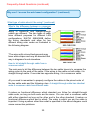
1
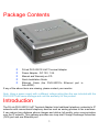
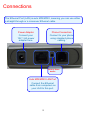
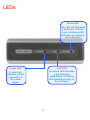
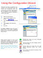
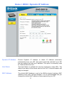
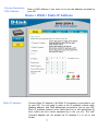
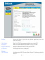
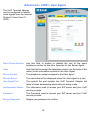
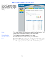
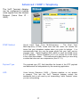
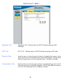
D-Link DVG-2001S VoIP Terminal Adapter Manual Building Networks for People Ver 1.00 651US2001S15 Contents Package Contents........................................................................................................... 1 Introduction ..................................................................................................................... 1 Connections .................................................................................................................... 2 LEDs ................................................................................................................................. 3 Features ........................................................................................................................... 4 Using the Configuration Wizard .................................................................................... 5 Home > WAN > Dynamic IP Address .......................................................................... 6 Home > WAN > Static IP Address ............................................................................... 7 Home > WAN > PPPoE ............................................................................................... 8 Advanced > VOIP > Server Configuration................................................................. 11 Advanced > VOIP > Provisioning .............................................................................. 13 Advanced > VOIP > STUN Configuration.................................................................. 14 Advanced > VOIP > User Agent ................................................................................ 15 Advanced > VOIP > Peer to Peer.............................................................................. 16 Advanced > VOIP > Telephony ................................................................................. 17 Advanced > Misc. ...................................................................................................... 18 Tools > Admin............................................................................................................ 19 Tools > System .......................................................................................................... 20 Tools > Firmware ....................................................................................................... 21 Tools > Config............................................................................................................ 22 Tools > Save & Reboot.............................................................................................. 22 Status > Device Info................................................................................................... 23 Status > Stats ............................................................................................................ 23 Status > Cable Tester ................................................................................................ 25 ii Help............................................................................................................................ 26 Technical Specifications .............................................................................................. 27 Frequently Asked Questions ....................................................................................... 29 iii Package Contents • • • • • D-Link DVG-2001S VoIP Terminal Adapter Power Adapter - DC 12V, 1.2A Manual and Warranty on CD Quick Installation Guide Ethernet Cable (the DVG-2001S’s Ethernet port is Auto-MDIX) If any of the above items are missing, please contact your reseller. Note: Using a power supply with a different voltage rating than the one included with the DVG-2001S will cause damage and void the warranty for this product. Introduction The D-Link DVG-2001S VoIP Terminal Adapter links traditional telephony networks to IP networks with conventional telephony devices such as analog phones or fax machines. It can reduce long distance phone charges and deliver toll-quality voice communication over the IP network. This gateway provides one loop start Foreign Exchange Subscriber (FXS) port and one Ethernet port. 1 Connections The Ethernet Port (LAN) is auto MDI/MDIX, meaning you can use either a straight-through or a crossover Ethernet cable. Power Adapter Phone Connection Connect your 12V 1.2A power adapter here. Connect to your phone using standard phone cabling. Factory Reset button Auto MDI/MDIX LAN Port Connect the Ethernet cable from computers on your LAN to this port. 2 LEDs Phone LED This LED will light when a telephone is off the hook. A blinking LED indicates an incoming call is detected Power LED LAN LED A solid light indicates a valid connection to the power supply. An active LED indicates a link has been established. A blinking LED indicates activity on the LAN port. 3 Features One Foreign Exchange Subscriber (FXS) POTS port (RJ-11 Jack) One NWay 10/100BASE-TX Fast Ethernet port for network connection Voice Activity Detection (VAD)/Comfort Noise Generation (CNG) Silence suppression to reduce bandwidth consumption Adaptive jitter buffer for smooth voice reception Lost packet recovery ability for improved voice quality Support QoS (Quality of Service) for voice quality guarantee Built-in PPPoE function to support dial-up connection for broadband technology IP address assignment using DHCP or static configuration Support Caller ID function Remote configuration and management over the Internet using web browsers 4 Using the Configuration Wizard 10.1.1.1 Whenever you want to configure your network or the DVG-2001S, you can access the Configuration Menu by opening the web-browser and typing in the IP Address of the DVG-2001S. The DVG-2001S default IP Address is shown to the right: • • • • • Open the web browser Type in the IP Address of the Router (http://10.1.1.1) Type admin in the User Name field Type admin in the Password field Click OK The Home > Wizard screen will appear. Please refer to the Quick Installation Guide for more information regarding the Setup Wizard. These buttons appear on most of the configuration screens in this section. Please click on the appropriate button at the bottom of each screen after you have made a configuration change. Clicking this button will save configured settings to the router. Note: if you have changed the default IP Address assigned to the DVG-2001S, make sure to enter the correct IP Address. Clicking Help will provide the user with helpful information about the current window. Clicking Cancel will clear changes made to the current page. Click refresh will refresh the statistics of the current window. Using the Configuration Menu (contin 5 Home > WAN > Dynamic IP Address Dynamic IP Address Choose Dynamic IP Address to obtain IP Address information automatically from your ISP. This option should be selected if your ISP has not supplied you with an IP address. This option is commonly used for Cable modem services. Host Name The Host Name is optional but may be required by some ISPs. The default host name is the device name of the VoIP Terminal Adapter and may be changed. MAC Address The default MAC Address is set to the WAN’s physical interface MAC address on the VoIP Terminal Adapter. It is not recommended that you change the default MAC address unless required by your ISP. 6 Primary/Secondary DNS Address Enter a DNS Address if you wish not to use the address provided by your ISP. Home > WAN > Static IP Address Static IP Address Choose Static IP Address if all WAN IP information is provided to you by your ISP. You will need to enter in the IP address, subnet mask, gateway address, and DNS address(es) provided to you by your ISP. Each IP address entered in the fields must be in the appropriate IP form, which are four octets separated by a dot (x.x.x.x). The VoIP Terminal Adapter will not accept the IP address if it is not in this format. 7 IP Address Input the public IP Address provided by your ISP. Subnet Mask Input your Subnet mask. (All devices in the network must have the same subnet mask.) Default Gateway Input the public IP address of the ISP to which you are connecting. Primary DNS Address Secondary DNS Address Input the primary DNS (Domain Name Server) IP address provided by your ISP This is an optional DNS Address entry to be used if the primary DNS Fails. Home > WAN > PPPoE Choose PPPoE (Point to Point Protocol over Ethernet) if your ISP uses a PPPoE connection. Your ISP will provide you with a username and password. This option is typically used for DSL services. Select Dynamic PPPoE to obtain an IP address automatically for your PPPoE connection. Select Static PPPoE to use a static IP address for your PPPoE connection. 8 PPPoE Choose this option if your ISP uses PPPoE. (Most DSL users will select this option.) User Name Enter The PPPoE user name provided to you by your ISP. Password Enter The PPPoE password provided to you by your ISP. Retype Password Retype the password entered in the previous field. IP Address This displays the current IP address. Primary DNS Address Input the primary DNS (Domain Name Server) IP address provided by your ISP. 9 Secondary DNS Address This is an optional DNS Address entry to be used if the primary DNS fails. Click Apply to set any changes made to the memory of the VoIP Terminal Adapter. Click Connect to initiate a PPPoE connection. Click Disconnect to end a PPPoE connection. 10 Advanced > VOIP > Server Configuration The VoIP Terminal Adapter can be configured to handle voice signals over the Internet Protocol (Voice Over IP − VOIP). The screen shown to the right, along with those on the following pages are used to configure your router to communicate with the devices that will send and receive telephone calls over the Internet. Server FQDN Use this drop-down menu to Enable or Disable the Server Fully Qualified Domain Name (FQDN) function. This is disabled when the SIP URL domain name is different from the SIP proxy server domain name. The phone will then use the domain name in Domain Name field as part of SIP URL but send and receive SIP messages through the SIP proxy server defined in the Service Domain field. IP Address Enter the IP address of the SIP Server in this field. Domain Name Enter the domain name corresponding to the IP address entered above in this field. Port Enter the SIP server’s listening port for the SIP in this field. Leave this field set to the default if your VoIP service provider did not give you a server port number for SIP. Service Domain Enter the SIP service domain name in this field. URL Format Select SIP-URL to have the router include the domain name with the SIP number in the SIP messages that it sends. 11 Select TEL-URL to have the router use the SIP number without a domain name in the SIP messages that it sends. User Parameter Phone You can set this to Enabled or Disabled. This determines whether or not the phone number is appended to the information forwarded to your SIP server. Your VoIP service provider will instruct you on which setting to use. Caller ID Delivery You can set this to YES or NO. This determines whether CID is received. Display CID You can set this to Enabled or Disabled. This determines whether to display Caller ID. Timer T2 Use the drop-down menu provided to select the desired time increment. Initial Unregister You can set this to Enabled or Disabled. The default is Enabled. Register Expiration Use this field to set how long the router will wait before sending a repeat registration request if a registration attempt fails or there is no response from the registration server. Session Expires This field will set the longest time that the router will allow a SIP session to remain idle (without traffic) before dropping it. Min-SE When two SIP devices negotiate a SIP session, they must negotiate a common expiration time for idle SIP sessions. This field sets the shortest expiration time that the router will accept. The router checks the session expiration values of incoming SIP INVITE requests against the minimum session expiration value that you enter here. If the session expiration of an incoming INVITE request is less than this value, the router negotiates with the other SIP device to increase the session expiration value to match the minimum session expiration value. Session Expires Refresher This determines which side of an expired call session will initiate the session refresh. uac – specifies the Caller side will initiate the session refresh. uas – specifies the Call receiver (the “Callee”) will initiate the session refresh.. 12 Advanced > VOIP > Provisioning Provisioning is a function that automatically updates your DVG-2001S’s VoIP configuration by using a TFTP server located on the Internet. If you have accesses to such a service, you will need to know the URL and Proxy Address of the Provisioning Server. Provisioning Function Use this drop-down menu to enable or disable the Provisioning Function on the VoIP Terminal Adapter. SSL Use the drop-down menu to enable Secure Shell (SSL). Server URL Enter the URL of the Provisioning Server in this field. Proxy Address Enter the IP address of the Proxy Server in this field. Proxy Port Number Enter the port number the Proxy Server will use to make the connection in this field. 13 Advanced > VOIP > STUN Configuration Simple Traversal of UDP over NAT (STUN) − is a protocol that enables a VoIP device, such as this router or an IP phone, to detect the presence and type of NAT behind which the phone is placed. This router supports STUN and can intelligently modify the private IP address and port in its SIP/SDP message by using the NAT mapped public IP address and port through a series of STUN queries against a STUN server located on the public Internet. This will allow SIP signaling and RTP media to successfully traverse a NAT without requiring any configuration changes on the NAT. STUN is useful if you need to use the DVG-2001S behind a modem or router that provides the connection to your ISP and then to the Internet and does not support symetric NAT. You will need access to a STUN server on the Internet and its IP address to use STUN on the DVG-2001S. STUN State Use this drop-down menu to Enable or Disable STUN on the router. STUN Server IP Address Enter the IP address of a STUN server in this field. STUN Server Port Enter the port number the STUN server will use in this field. If you do not have any information as to the proper port number, leave the default setting here. STUN ReqInterval This determines the amount of time, in seconds, between STUN requests. If you do not have any information as to the proper interval, leave the default setting here. STUN NAT Type Displays the result of the STUN NAT examination. 14 Advanced > VOIP > User Agent The VoIP Terminal Adapter can be configured to handle voice signals over the Internet Protocol (Voice Over IP − VOIP). Same Phone Number Use this field to enable or disable the use of the same telephone number for the User Agent as for the Server Agent. Index Use this field to assign the telephone socket (on the back of the router) to the information entered in the User Agent. Phone Number The telephone number assigned to the User Agent. Domain Name The name that will be displayed when the User Agent is in use. User Agent Port This selects the port number the VoIP Terminal Adapter will listen to when determining when calls are being made. Authentication Name The Username used to access your SIP server and your VoIP service provider. Password The Password used to access your SIP server and your VoIP service provider. Retype Password Retype your password to confirm. 15 Advanced > VOIP > Peer to Peer The VoIP Terminal Adapter can be configured to handle voice signals over the Internet Protocol (Voice Over IP − VOIP). Index This field assigns the telephone socket (on the back of the router) to the information entered in the User Agent. Phone Number The telephone number assigned to this entry. User IP Address Enter the IP address of the remote peer in this field. Port Enter the UDP port number the remote peer will use to make the connection in this field. If you do not have any information as to the proper port number, leave the default setting here. 16 Advanced > VOIP > Telephony The VoIP Terminal Adapter can be configured to handle voice signals over the Internet Protocol (Voice Over IP − VOIP). DTMF Method Out-of band Dual Tone Multi-frequency – The Dual Tone Multi-frequency (DTMF) mode sets how the router will handle the tones that your telephone makes when you push its buttons. It is recommended that you use the same mode that your VoIP service provider uses. Select Enabled (RFC 2833) to send the DTMF tones in RTP packets. Select Disabled (G.711) to include the DTMF tones in the voice date stream. This method works best when you are using a codec that does not use compression (like G.711). Payload Type The payload type (PT) field identifies the format of the RTP payload and determines its interpretation by the receiving application VAD Voice Activity Detection (VAD) – Detects whether or not speech is present. This lets the VoIP Terminal Adapter reduce the bandwidth that a call uses by not transmitting “silent Packets” when you are not speaking. 17 Advanced > Misc. Signaling ToS Signaling ToS -ToS field value in UDP IP Packets carrying a SIP Message RTP ToS RTP ToS - ToS field value in UDP IP Packets carrying a RTP data Receive Gain Used to raise or lower the gain (volume) of signals that come in from the IP and are sent to the line-side or trunk-side interface. The Rx Gain dB level may be set in 0.5 db increments from –20 dBm to 20 dBm. Transmission Gain Used to raise or lower the gain (volume) of signals that go out to the IP from the line-side or trunk-side interface. The Tx Gain dB level may be set in 0.5 db increments from –20 dBm to 20 dBm. 18 Tools > Admin Change System Password To change the password used to access the web manager, type the New Password and Confirm Password to be certain you have typed it correctly. Click the Apply button to activate the new password. The System User Name remains “admin”, this cannot be changed using the web manager interface. Be sure to save the new setting. Administrator admin is the Administrator login name. Password Enter the password here and the same password in the Confirm Password field. This will be the password that the administrator will use to gain access to the configuration menu of the device. The default password is “admin.” User user is the User login name. Password Enter the password here and the same password in the Confirm Password field. This will be the password that the users will use to gain access to the configuration menu of the device. Users will have limited privileges on this device. The default password is “admin.” Remote Management Remote management allows the VoIP Terminal Adapter to be configured from the Internet by a web browser. A username and password is still required to access the Web-Management interface. In general, only a member of your network can browse the built-in web pages to perform Administrator tasks. This feature enables you to perform Administrator tasks from the remote (Internet) host. Web Port Number The port number used to access the VoIP Terminal Adapter. The default port number for web management is 80. 19 Tools > System Reset to Factory Default Click Reset to Factory Default to restore the settings. 20 Tools > Firmware You can upgrade the firmware of the VoIP Terminal Adapter here. Make sure the firmware you want to use is on the local hard drive of the computer. Please check the D-Link Support site for firmware updates at http://support.dlink.com. You can download firmware upgrades to your hard drive from the D-Link support site. Firmware Update Click on the link in this screen to find out if there is an updated firmware; if so, download the new firmware to your hard drive. File Name Enter the firmware file name and DOS path in this field. For example, C:\firmware.had Click Apply to complete the firmware upgrade. 21 Tools > Config This screen allows you to backup and restore configuration files. Click Backup to initiate the backing up of a configuration file. Click Upload to initiate the uploading of the configuration file once you have located it by using the Browse button. Tools > Save & Reboot This screen allows you to save and reboot the VoIP Terminal Adapter. Click the Reboot button. 22 Status > Device Info This page displays the current information for the DVG-2001S. WAN MAC Address: MAC address of the DVG-2001S IP Address: WAN/Public IP Address Subnet Mask: WAN/Public Subnet Mask Default Gateway: WAN/Public Gateway IP Address Status > Stats The VoIP Terminal Adapter keeps a running log of events and activities occurring on the device. If it is rebooted, the logs are automatically cleared. You may save the log files under Log Settings. 23 The screen above displays the Traffic Statistics. Here you can view the amount of packets that pass through the DVG-2001S on the WAN port. The traffic counter will reset if the device is rebooted or can be reset by clicking the Reset button. To refresh current statistics, click the Refresh button. 24 Status > Cable Tester The VoIP Terminal Adapter offers you to conduct a Ping test by entering the IP address in the field below and then clicking the test button. . 25 Help The Help tab will give basic information referring to various screens located in the VoIP Terminal Adapter. To view a specific section, click on its hyperlinked name. A new window of information will appear. 26 Technical Specifications Standards: IEEE 802.3 IEEE 802.3u Device Management: HTTP 1.0 Web-Based - Internet Explorer v6 or later; Netscape Navigator v6 or later; or other Java-enabled browsers DHCP Client Auto-provisioning Telnet TFTP Client Performance monitoring using DSP/Ethernet statistics Operating Temperature: 32ºF to 131 ºF (0ºC to 55ºC) Humidity Range: 5% to 95% Non-condensing Safety and Emissions: FCC part15 LEDs: Power LAN Phone Physical Dimensions: L = 3.25 inches (82.46 mm) W = 3.54 inches (90 mm) 27 Technical Specifications H = 1.22 inches (31 mm) Security: User Authentication Administration – Username/Password control for Telnet and Web configuration SIP Authentication Provisioning Security using HTTPS and SSL/TLS client certificate encryption and authentication VoIP NAT Traversal – SIP/STUN Miscellaneous: PPPoE (RFC 2516) Power Input: Ext. Power Supply DC 12V, 1.2A Weight: 0.1225kg Warranty: 3 year (depends on D-Link global warranty policy) Telephony Support: Call Control Protocol – SIP (RFC 3261) CODEC – G.711 (A-law and U-law), G.723.1, G.726, and G.729A Echo Cancellation – G.168 DTMF Relay – G.711 (in band) FAX Support 28 Frequently Asked Questions Why can´t I access the web based configuration? When entering the IP Address of the DVG-2001S (10.1.1.1), you are not connecting to the Internet or have to be connected to the Internet. The device has the utility built-in to a ROM chip in the device itself. Your computer must be on the same IP subnet to connect to the web-based utility, however. To resolve difficulties accessing a web utility, please follow the steps below. S t e p 1 Verify physical connectivity by checking for solid link lights on the device. If you do not get a solid link light, try using a different cable or connect to a different port on the device if possible. If the computer is turned off, the link light may not be on. What type of cable should I be using? The following connections require a Crossover Cable: Computer to Computer Computer to Uplink Port Computer to Access Point Computer to Print Server Computer/XBOX/PS2 to DWL-810 Computer/XBOX/PS2 to DWL-900AP+ Uplink Port to Uplink Port (hub/switch) Normal Port to Normal Port (hub/switch) The following connections require a Straight-through Cable: Computer to Residential Gateway/Router Computer to Normal Port (hub/switch) Access Point to Normal Port (hub/switch) Print Server to Normal Port (hub/switch) Uplink Port to Normal Port (hub/switch) Rule of Thumb: ”If there is a link light, the cable is right.” 29 Frequently Asked Questions (continued) Why can´t I access the web based configuration? (continued) What type of cable should I be using? (continued) What´s the difference between a crossover cable and a straight-through cable? The wiring in crossover and straight-through cables are different. The two types of cable have different purposes for different LAN configurations. EIA/TIA 568A/568B define the wiring standards and allow for two different wiring color codes as illustrated in the following diagram. *The wires with colored backgrounds may have white stripes and may be denoted that way in diagrams found elsewhere. How to tell straight-through cable from a crossover cable: The main way to tell the difference between the two cable types is to compare the wiring order on the ends of the cable. If the wiring is the same on both sides, it is straight-through cable. If one side has opposite wiring, it is a crossover cable. All you need to remember to properly configure the cables is the pinout order of the two cable ends and the following rules: A straight-through cable has identical ends A crossover cable has different ends It makes no functional difference which standard you follow for straight-through cable ends, as long as both ends are the same. You can start a crossover cable with either standard as long as the other end is the other standard. It makes no functional difference which end is which. The order in which you pin the cable is important. Using a pattern other than what is specified in the above diagram could cause connection problems. 30 Frequently Asked Questions (continued) Why can´t I access the web based configuration? (continued) When to use a crossover cable and when to use a straight-through cable: Computer to Computer – Crossover Computer to an normal port on a Hub/Switch – Straight-through Computer to an uplink port on a Hub/Switch – Crossover Hub/Switch uplink port to another Hub/Switch uplink port – Crossover Hub/Switch uplink port to another Hub/Switch normal port – Straight-through 31 Frequently Asked Questions (continued) Why can´t I access the web based configuration? (continued) S t e p 2 Disable any Internet security software running on the computer. Software firewalls like Zone Alarm, Black Ice, Sygate, Norton Personal Firewall, etc. might block access to the configuration pages. Check the help files included with your firewall software for more information on disabling or configuring it. S t e p 3 Configure your Internet settings. Go to Start>Settings>Control Panel. Double-click the Internet Options icon. From the Security tab, click the button to restore the settings to their defaults. Click to the Connection tab and set the dialup option to Never Dial a Connection. Click the LAN Settings button Nothing should be checked. Click OK Go to the Advanced tab and click the button to restore these settings to their defaults Click OK. Go to the desktop and close any open windows 32 Frequently Asked Questions (continued) Why can´t I access the web based configuration? (continued) S t e p 4 Check your IP Address. Your computer must have an IP Address in the same range of the device you are attempting to configure. Most D-Link devices use either 10.0.0.1 or the 192.168.0.X range. How can I find my IP Address in Windows 95, 98, or ME? Step 1 Click on Start and then click on Run. Step 2 The Run Dialogue Box will appear. Type winipcfg in the window as shown then click OK. Step 3 The IP Configuration window will appear, displaying your Ethernet Adapter Information. Select your adapter from the drop-down menu. If you do not see your adapter in the drop-down menu, your adapter is not properly installed. 33 Frequently Asked Questions (continued) Why can´t I access the web based configuration? (continued) Step 4 After selecting your adapter, it will display your IP Address, subnet mask, and default gateway. Step 5 Click OK to close the IP Configuration window. S t e p 4 (continued) Check your IP Address. Your computer must have an IP Address in the same range of the device you are attempting to configure. Most D-Link devices use either 10.0.0.1 or the 192.168.0.X range. 34 Frequently Asked Questions (continued) Why can´t I access the web based configuration? (continued) How can I find my IP Address in Windows 2000/XP? Step 1 Click on Start and select Run. Step 2 Type cmd then click OK. Step 3 From the Command Prompt, enter ipconfig. It will return your IP Address, subnet mask, and default gateway Step 4 Type exit to close the command prompt. 35 Frequently Asked Questions (continued) Why can´t I access the web based configuration? (continued) S t e p 4 (continued) Check your IP Address. Your computer must have an IP Address in the same range of the device you are attempting to configure. Your D-Link device uses 10.1.1.1. Make sure you take note of your computer´s Default Gateway IP Address. The Default Gateway is the IP Address of the D-Link VoIP Terminal Adapter. By default, it should be 10.1.1.1. How can I assign a Static IP Address in Windows XP? Step 1 Click on Start > Control Panel > Network and Internet Connections > Network connections. Step 2 See Step 2 for Windows 2000 and continue from there. How can I assign a Static IP Address in Windows 2000? Step 1 Right-click on My Network Places and select Properties. Step 2 Right-click on the Local Area Connection which represents your network card and select Properties. Highlight Internet Protocol (TCP/ IP) and click Properties. 36 Frequently Asked Questions (continued) Why can´t I access the web based configuration? (continued) How can I assign a Static IP Address in Windows 2000? (continued) Click “Use the following IP Address” and enter an IP Address that is on the same subnet as the LAN IP Address on your VoIP Terminal Adapter. Example: If the VoIP Terminal Adapter´s LAN IP Address is 10.1.1.1, make your IP Address 10.x.x.x where x = 2-254. Make sure that the number you choose is not in use on the network. Set the Default Gateway to be the same as the LAN IP Address of your VoIP Terminal Adapter (10.1.1.1). Set the Primary DNS to be the same as the LAN IP address of your VoIP Terminal Adapter (10.1.1.1). The Secondary DNS is not needed or enter a DNS server from your ISP. Click OK twice. You may be asked if you want to reboot your computer. Click Yes. 37 Frequently Asked Questions (continued) Why can´t I access the web based configuration? (continued) How can I assign a Static IP Address in Windows 98/Me? Step 1 From the desktop, right-click on the Network Neighborhood icon (Win ME My Network Places) and select Properties. Highlight TCP/IP and click the Properties button. If you have more than one adapter, then there will be a TCP/IP “Binding” for each adapter. Highlight TCP/IP > (your network adapter) and then click Properties. 38 Frequently Asked Questions (continued) Why can´t I access the web based configuration? (continued) How can I assign a Static IP Address in Windows 98/Me? (continued) Step 2 Click Specify an IP Address. Enter in an IP Address that is on the same subnet as the LAN IP Address on your VoIP Terminal Adapter. Example: If the VoIP Terminal Adapter´s LAN IP Address is 10.1.1.1, make your IP Address 10.x.x.x where x is between 2-254. Make sure that the number you choose is not in use on the network. Step 3 Click on the Gateway tab. Enter the LAN IP Address of your VoIP Terminal Adapter here (10.1.1.1). Click Add when finished. Step 4 Click on the DNS Configuration tab. Click Enable DNS. Type in a Host (can be any word). Under DNS server search order, enter the LAN IP Address of your VoIP Terminal Adapter (10.1.1.1). Click Add. Step 5 Click OK twice. When prompted to reboot your computer, click Yes. After you reboot, the computer will now have a static, private IP Address. 39 Frequently Asked Questions (continued) Why can´t I access the web based configuration? (continued) S t e p 5 Access the web management. Open your web browser and enter the IP Address of your D-Link device in the address bar. This should open the login page for the web management. Follow instructions to login and complete the configuration. 40 Frequently Asked Questions (continued) How can I setup my router to work with a Cable modem connection? S t e p 1 Power cycle the cable modem and router: Turn the cable modem off (first). Turn the router off Leave them off for 2 minutes.** Turn the cable modem on (first). Wait until you get a solid cable light on the cable modem. Turn the router on. Wait 30 seconds. ** If you have a Motorola (Surf Board) modem, leave off for at least 5 minutes. S t e p 2 Follow step 1 again and log back into the web configuration. Click the Status tab and click the Device Info button. Static Cable Connection S t e p 3 Log into the web based configuration by typing in the IP Address of the VoIP Terminal Adapter (default:10.1.1.1) in your web browser. The username is admin (all lowercase) and the password is admin (all lowercase). S t e p 4 Click the Home tab and click the WAN button. Select Static IP Address and enter your static settings obtained from the ISP in the fields provided. If you do not know your settings, you must contact your ISP. S t e p 5 Click on Apply and then click Continue to save the changes. S t e p 6 Click the Status tab and click the Device Info button. Your IP Address information will be displayed under the WAN heading. 41 Frequently Asked Questions (continued) How can I setup my router to work with Earthlink DSL or any PPPoE connection? Make sure you disable or uninstall any PPPoE software such as WinPoet or Enternet 300 from your computer or you will not be able to connect to the Internet. S t e p 1 Upgrade Firmware if needed. (Please visit the D-Link tech support website at: http://support.dlink.com for the latest firmware upgrade information.) S t e p 2 Take a paperclip and perform a hard reset. With the unit on, use a paperclip and hold down the reset button on the back of the unit for 10 seconds. Release it and the router will recycle, the lights will blink, and then stabilize. S t e p 3 After the VoIP Terminal Adapter stabilizes, open your browser and enter 10.1.1.1 into the address window and hit the Enter key. When the password dialog box appears, enter the username admin and leave the password blank. Click OK. If the password dialog box does not come up repeat Step 2. Note: Do not run Wizard. S t e p 4 Click on the WAN button on left-hand side of the Home WAN screen. Select PPPoE. S t e p 5 In the username field enter ELN/[email protected] and your password, where username is your own username. For SBC Global users, enter [email protected]. For Ameritech users, enter [email protected]. For BellSouth users, enter [email protected]. For Mindspring users, enter [email protected]. For most other ISPs, enter username. Note: If you experience problems accessing certain websites and/or email issues, please set the MTU to a lower number such as 1472, 1452, etc. Contact your ISP for more information and the proper MTU setting for your connection. Step 6 Click Apply. When prompted, click Continue. Once the screen refreshes, unplug the power to the D-Link VoIP Terminal Adapter. 42 Frequently Asked Questions (continued) How can I setup my router to work with Earthlink DSL or any PPPoE connection? (continued) Step 7 Turn off your DSL modem for 2-3 minutes. Turn back on. Once the modem has established a link to your ISP, plug the power back into the D-Link VoIP Terminal Adapter. Wait about 30 seconds and log back into the router. Step 8 Click on the Status tab in the web configuration where you can view the device info. You should now see that the device info will show an IP Address, verifying that the device has connected to a server and has been assigned an IP Address. Can I use my D-Link VoIP Terminal Adapter to share my Internet connection provided by AOL DSL Plus? In most cases, the answer is yes. AOL DSL+ may use PPPoE for authentication bypassing the client software. If this is the case, then our routers will work with this service. Please contact AOL if you are not sure. To set up your VoIP Terminal Adapter: Step 1 Log into the web-based configuration (10.1.1.1) and configure the WAN side to use PPPoE. Step 2 Enter your screen name followed by @aol.com for the user name. Enter your AOL password in the password box. Step 3 You will have to set the MTU to 1400. AOL DSL does not allow for anything higher than 1400. Step 4 Apply settings. Step 5 Recycle the power to the modem for 1 minute and then recycle power to the router. Allow 1 to 2 minutes to connect. If you connect to the Internet with a different Internet service provider and want to use the AOL software, you can do that without configuring the VoIP Terminal Adapter’s firewall settings. You need to configure the AOL software to connect using TCP/IP. Go to http://www.aol.com for more specific configuration information of their software. 43 Technical Support You can find software updates and user documentation on the D-Link website. D-Link provides free technical support for customers within the United States and within Canada for the duration of the warranty period on this product. U.S. and Canadian customers can contact D-Link technical support through our website, or by phone. Tech Support for customers within the United States: D-Link Technical Support over the Telephone: (888) 843-6100 Hours of Operation: 8:00AM to 6:00PM PST D-Link Technical Support over the Internet: http://support.dlink.com email:[email protected] Tech Support for customers within Canada: D-Link Technical Support over the Telephone: (800) 361-5265 Monday to Friday 7:30am to 12:00am EST D-Link Technical Support over the Internet: http://support.dlink.ca email:[email protected] 44