1
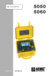
OPERATION MANUAL
TH2689/TH2689A
Capacitor Leakage Current/IR Meter
TH2689/89A Operation manual
Content
CHAPTER 1
INTRODUCTION...................................................................................... 2-1
1.1 INTRODUCTION ............................................................................................................... 2-1
1.2 CONDITION ..................................................................................................................... 2-1
1.2.1 POWER a ................................................................................................................... 2-1
1.2.2 ENVIRONMENTAL TEMPERATURE AND HUMIDITY .............................................................. 2-1
1.2.3 WARM-UP .................................................................................................................... 2-2
1.2.4 CAUTION ! ................................................................................................................ 2-2
5.1 DIMENSION AND WEIGHT .................................................................................................. 5-2
5.2 SAFETY .......................................................................................................................... 5-2
5.2.1 INSULATED RESISTANCE ................................................................................................ 5-2
5.2.2 INSULATION INTENSITY .................................................................................................. 5-3
5.2.3 LEAKAGE CURRENT ...................................................................................................... 5-3
5.3 ELECTROMAGNETIC COMPATIBILITY .................................................................................. 5-3
CHAPTER 2 INSTRUCTION OF FRONT PANEL .................................................................... 4
2.1 INSTRUCTION OF FRONT PANEL .............................................................................................. 4
2.2 INSTRUCTION OF REAR PANEL................................................................................................ 5
CHAPTER 3 OPERATION ....................................................................................................... 7
3.1 CONNECTION OF (DUT)................................................................................................... 7
3.2 OPERATION .......................................................................................................................... 8
3.2.1 MAIN INDEX.................................................................................................................... 8
3.2.2 SEQ. TEST ...................................................................................................................... 9
3.2.3 SINGLE STEP MANUAL TEST PAGE ..................................................................................... 14
3.2.4 CONTINUES AUTO TEST PAGE ........................................................................................... 16
3.2.5 NULL TEST PAGE .............................................................................................................. 17
3.2.6 ALUMINIUM FOIL WITHSTANDING VOLTAGE TEST PAGE ......................................................... 18
3.2.7 COMPARE FUNCTION SETTING PAGE .................................................................................. 23
3.2.8 FILE STORAGE PAGE ........................................................................................................ 24
3.2.9 SYSTEM CONFIGURATION PAGE ........................................................................................ 26
CHAPTER 4 TEST PERFORMANCE .................................................................................... 38
4.1(L.C./I.R. TEST) ............................................................................................................ 38
4.1.1 PARAMETER .................................................................................................................... 38
4.1.2 TEST SIGNAL ................................................................................................................... 38
4.1.3 BASIC ACCURACY ............................................................................................................ 39
4.1.4 DISPLAY RANGE ............................................................................................................... 39
4.1.5 TEST TIME ....................................................................................................................... 39
4.1.6 (NULL) .................................................................................................................... 39
-i-
TH2689/89A Operation manual
4.2(W.V. TEST).................................................................................................................. 39
4.2.1 TEST PARAMETER ............................................................................................................ 39
4.2.2 TEST SIGNAL ................................................................................................................... 39
4.2.3 DISPLAY RANGE ............................................................................................................. 39
CHAPTER 5 REMOTE CONTROL ........................................................................................ 41
5.1 RS232C INTERFACE INTRODUCTION ................................................................................... 41
5.1.1 RS232C CONNECTION..................................................................................................... 41
5.1.2 COMMUNICATION WITH A COMPUTER ................................................................................. 43
5.2 GPIB................................................................................................................................. 43
5.2.1 GPIB BUS....................................................................................................................... 43
5.2.2 GPIB FUNCTION .............................................................................................................. 45
5.2.3 GPIB ADDRESSING .......................................................................................................... 46
CHAPTER 6 COMMAND REFERENCE ................................................................................ 47
6.1 SHARING COMMAND INSTRUCTION ....................................................................................... 47
6.2 SCPI ORDER STRUCTURE................................................................................................... 48
6.2.1 ORDER STRUCTURE INSTRUCTION .................................................................................... 49
6.3 ORDER SYNTAX .................................................................................................................. 50
6.4 SCPI ORDER INSTRUCTION ................................................................................................. 51
6.4.1 ABORT ORDER SYSTEM ................................................................................................... 51
6.4.2 CALCULATE ORDER SYSTEM ............................................................................................ 51
6.4.3 DISPLAY ORDER SYSTEM ................................................................................................. 53
6.4.4 LCTEST ORDER SYSTEM .................................................................................................. 53
6.4.5 WVTEST ORDER SYSTEM ................................................................................................. 55
6.4.6 TRIGGER ORDER SYSTEM................................................................................................ 56
6.4.7 SYSTEM ORDER SYSTEM ................................................................................................. 57
6.5 ERROR INFORMATION.......................................................................................................... 58
CHAPTER 7 SORTING INTERFACE INSTRUCTION ........................................................... 59
7.1 HANDLER INTERFACE ....................................................................................................... 59
7.2 THE JUMPER SET ON HANDLER BOARD .............................................................................. 60
7.3 HANDLER INTERFACE SIGNAL DIAGRAM.............................................................................. 61
- ii -
TH2689/89A Operation manual
Chapter 1 Introduction
Thanks very much for choosing and using our product. If you have any questions after
reviewing this manual, please contact your local representative or call directly to our application
engineers for further consultation.
1.1
Introduction
Basic specification:(more in Chapter 4)
z Test parameter:
Leakage current test:L.C.(Leakage Current),I.R.(Isolated Resistance)
Withstanding voltage test:Tr,Vt
z Basic accuracy:
L.C.---------------±(0.3%+0.05uA)
z Test range:
L.C.---------------0.000 uA~ 20.00 mA
z Test voltage/charging current:
Test voltage LEV = 1.0V ~ 100V,resolution 0.1V
= 101V ~ 800V,resolurion 1V; ±(0.5%+0.2V)[TH2689]
= 101V ~ 500V,resolution 1V; ±(0.5%+0.2V)[TH2689A]
Charging current
LEV ≤ 100V:0.5 mA ~ 500 mA,resolution 0.5 mA
> 100V:0.5 mA ~ IMAX,resolution 0.5 mA; ±(3%+0.05mA)
z Correction : Null
z IEEE-488 interface (optional): this interface provides convenience for instrument
and computer or other instruments to make a automatical test system.
The command of RS-232C and IEEE-488 interface is written by SCPI format.
z HANDLER interface: the instrument is synchronized with the machinery processing
instrument in automatical test system, and the result is output to the machinery processing
instrument.
1.2 Condition
1.2.1
Power a
Voltage: 220V(1±10%)
Frequency: 50Hz/60Hz(1±5%)
Consumption: <120VA
1.2.2
Environmental temperature and humidity
Normal working temperature: 0°C~40°C,humidity: < 90%RH
2-1
TH2689/89A Operation manual
Reference working temperature: 20°C±8°C,humidity: < 80%RH
Transportation temperature:0°C~55°C,humidity:≤ 93%RH
1.2.3
Warm-up
Warm up time:≥ 20 min.
1.2.4
Caution
!
1.
Please do not operate the instrument in the places where is vibrative, dusty, under
direct sunlight, or where there is corrosive air.
2 Although the instrument has been specially designed for reducing the noise cased by
ac power, a place with low noise is still recommended. If this cannot be arranged, please make
sure to use power filter for the instrument.
3 Please store the instrument in the place where temperature is between 5℃ and 40℃,
humidity is less then 85% RH. If the instrument will not be put in use for a time, please have it
properly packed with its original box or a similar box for storing.
4 TH2816B has the cooling fan on the rear panel and cooling holes on both sides.
High temperature inside will decrease the measurement accuracy, so sufficient space must be
kept around the TH2816B to avoid obstructing the air flow of the cooling fans.
5 Don’t frequently turn on and off the instrument, doing so will lead to the loss of the
calibrated data and the data saved by users.
5.1 Dimension and weight
Dimension (W*H*D): 350mm*120mm*400mm
Weight: about 7kg
5.2 Safety
The instrument is the class I
5.2.1
Insulated resistance
Under the reference working condition,the insulated resistance between powerterminal
and shell is no less than 50MΩ;
Under transportaion condition,the insulated resistance between powerterminal and shell
is no less than 2MΩ;
5-2
TH2689/89A Operation manual
5.2.2
Insulation intensity
Under the reference working condition,the rated voltage between powerterminal and shell is
1.5kV, 50Hz AC voltage is 1 Min.,no arc phenomenon.
5.2.3
Leakage current
Leakage current is no larger than 3.5mA.
5.3 Electromagnetic compatibility
Power instaneous sensitivity is based on GB6833.4
Transmmission sensitivity is based on GB6833.6
Radiated interference is based on GB6833.10
5-3
TH2689/89A Operation manual
Chapter 2 Instruction of front panel
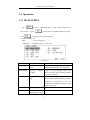
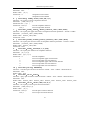
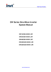
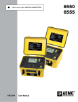
2.1 Instruction of front panel
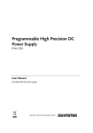
Figure 2-1
Figure 2-1 Instruction of front panel
No.
Name
Instruction
1
Brand and model
TH2689 or TH2689A
Capacitor Leakage Current/IR Meter
2
POWERa
Switch on and off 220V/110V power
3
LCD
4
SOFTKEYs
The five keys have different functions in
different menus
No.
Name
Instruction
5
DISPLAY
6
MAIN
7
SYSTEM
For entering system setup page
8
CURSOR
For controlling the movement of cursor on the
screen, the selected parameter is displayed
240*64 dot-matrix LCD
For entering the prevous page
For entering the main function page
4
TH2689/89A Operation manual
with highlight.
9
10
UNKNOW
Voltage
terminal
INPUT:current sampling terminal
output
HV(-):negative voltage output terminal;a
HV(+):voltage positive terminal;
11
Ground
Connect with shielding layer of the component
to be tested , in order to separate the
electromagnetic interface to improve the
accuracy and stability.
12
number/letter
keyboard
For inputting number or character if desired(file
name).
13
BACKSPACE
For deleting numbers or letters if desired.
14
ENTER
Confirm the inputed numbers .etc
15
DISCHARGE
The instrument enters discharging status.
16
CHARGE/TEST
Trigger test,when setting manual trigger,press
the key to trigger a test.
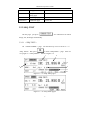
2.2 Instruction of rear panel
Figure 2-2
5
TH2689/89A Operation manual
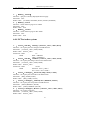
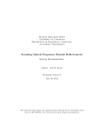
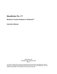
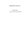
Figure 2-2 Instruction of rear panel
No.
1
2
3
Name
Instruction
RS232C
Provide the universal serial communication
interface for instrument and external device. All
parameter setup and command are set and
obtained by computer to realize the remote
control.
Provide universal parallel communication
IEEE488(optioanl) interface for instrument and external device,the
function is the same as 1
Ground
4
HANDLER
The instrument outputs compare result viathis
interface,and obtains “setup”signal via sorting
interface.
5
Label plate
Record the date, model, manufacturer .etc
6
3-cable power
socketa
Connect the 220V/50Hz or 110V/60Hz AC
power.
6
TH2689/89A Operation manual
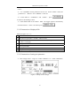
Chapter 3 Operation
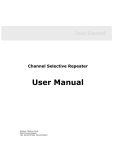
3.1 Connection of (DUT)
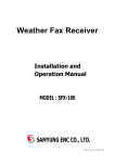
Figure 3-1
Note:
INPUT terminal is connected with positive terminal,
HV(-)outputs negative voltage,and connects the negative terminal of DUT.
7
TH2689/89A Operation manual
3.2 Operation
3.2.1 MAIN INDEX
Press
to enter <MAIN INDEX> page,use direction key to
move cursor ,press
press
to enter the corresponded subfunction page,
to return to the previous test page.
Shown as figure 3-2:
FILE
: file storage page;
Calibration : calibration page,not for user.
Figure 3-2
Page
Explaination
SEQ. TEST
In-turn
page
STEP TEST
One-step
test page
auto
Instruction
test
The process of charge, test, discharge is
finished automatically after triggering
manual
Trigger to enter charging status, and
enters test status after charging, manual
discharge is requried
CONT TEST
Sequence atuo test
page
Charge after triggering, enter test
status,once the external capacitor without
electricity is connected to the test
terminal, then discharge manually in auto
trigger charge, test.
NULL
Null test page
W.V. TEST
Aluminium
foil
withstanding voltage
8
TH2689/89A Operation manual
test page
COMPARE
Compare function
setting page
FILE
File storage page
Calibration
Calibration page
Not for user
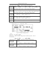
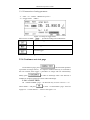
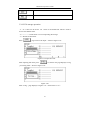
3.2.2 SEQ. TEST
On this page,just press
,the instrument can finish
charge, test, discharge automatically.
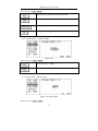
3.2.2.1 <SEQ.TEST>
On <MAIN INDEX> page,use direction key to move cursor to“(1)
SEQ. TEST”,then press
to enter<SEQ.TEST> page,there are
two pages on <SEQ.TEST>,shown as figure 3-3:
1
2
3
7
4
5
6
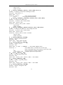
Figure 3-3(a)SEQ.TEST page 1
Figure 3-3(b)SEQ.TEST page 2
9
TH2689/89A Operation manual
※Note:
(1) In(CHARGE)status, parameter can’t be set,and in(TEST)status, the
parameter of (RANG)and(SPEED)can be set.
(2) In the status of (CHARGE) and (TEST), press
to return to the discharge status.
(3)when TRIG mode is set as BUS、EXT,the trigger signal is controlled by
external interface,and it is invalid to press
.
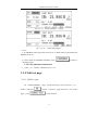
3.2.2.2 Instruction of displayed file
Shown as figure 3-3(a):
1
Name
2
Test function parameter(LC/IR)and test result
3
Compare result:
(√PASS),
(×HIGH),
(×LOW);if compare function is off,
there is no display
4
Voltage monitor
5
Current procedure
6
Softkey zone
7
Test parameter setup
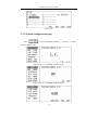
3.2.2.3 Instruction of setting test parameter
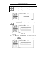
(1)Test voltage(LEV),range 1V~800V(TH2689)/ 1V~500V(TH2689A)
Figure 3-4 Setup of test voltage
10
TH2689/89A Operation manual
Move cursor to “LEV:100.0V”,operate according to the table below:
Coarse
urning
,
from
small
to
large
:
6.3→10.0→16.0→25.0→35.0→50.0→63.0→100.0→160.0→200.0→250.0→3
50.0→400.0→450.0→500.0(→550.0→600.0→630.0→800.0)
Coarse
turning
,
from
large
to
small
:
6.3←10.0←16.0←25.0←35.0←50.0←63.0←100.0←160.0←200.0←250.0←3
50.0←400.0←450.0←500.0(←550.0←600.0←630.0←800.0)
Fine turning,when LEV ≥ 100.0V,stepper is +1V;
When LEV < 100.0V,stepper is +0.1V
Fine turning,when LEV ≥ 100.0V,stepper is -1V;
When LEV < 100.0V,stepper is -0.1V
Numberic
key
Input test voltage value directly(default unit is V),press ENTER to confirm
(2)Charging current(CC),range 0.5mA~500mA
Figure 3-5 Setup of charging current
※Note:
When LEV ≤ 100V, Imax = 500mA;
When LEV > 100V,the Max. charge current is limited by power,and use
P=UI to obtain
Imax = P / LEV
— — —(P = 50W)
Move cursor to “CC: 15.0mA”,and operate according to the table below:
Coarse turning. When CC ≥ 100.0mA , stepper is
+50.0mA;
When CC < 100.0mA,stepper is +5.0mA;
Coarse turning. When CC > 100.0mA , stepper is
-50.0mA;
When CC ≤ 100.0mA,stepper is -5.0mA;
11
TH2689/89A Operation manual
Fine turning. Stepper is +0.5 mA;
Fine turning. Stepper is -0.5 mA;
Numberic key
Input charging current value directly(default unit is mA),
press ENTER to confirm
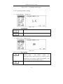
(3)(RANG),small character A means AUTO,H means HOLD
Figure 3-6 setup of range gear
Move cursor to“RANG: 2uA A”,operate according to the table below:
Auto range gear,‘A’is displayed in the current range
Lock range gear,‘H’is displayed in the current range
Select range gear,2uA→20uA→200uA→2mA→20mA
Select range gear,20mA→2mA→200uA→20uA→2uA
(4)(SPEED)
Figure 3-7 Setup of test speed
Move cursor to “SPEED: FAST”,operate according to the table below:
12
TH2689/89A Operation manual
Fast
Middle
Slow
Note:the speed is slower and the test result is more stable.
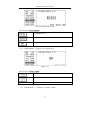
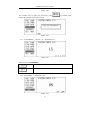
(5)(CHG T),range 0Sec~999Sec,
Figure 3-8 setup of charging time
Move cursor to “CHG T: 30S”, operate according to the table below:
Coarse turning. When CHG T ≥ 100Sec , stepper is
+100Sec;
When CHG T < 100Sec,stepper is +10Sec;
Coarse turning when CHG T > 100Sec,stepper is
-100Sec;
When CHG T ≤ 100Sec,stepper is -10Sec;
Fine turning. Stepper is +1 Sec;
Fine turning. Stepper is -1Sec;
Numberic key
Input charging time directly(default unit is Sec),press
ENTER to confirm
(6)delay test time(D T)
,range 0.2Sec~999.0Sec,the time is the one from
charge finishing to test starting, which is stable.
13
TH2689/89A Operation manual
Figure 3-9 Setup of delay test time
Move cursor to“D T: 0.2S”, operate according to the table below:
Coarse turning. When D T ≥ 100Sec,stepper is +10Sec;
When D T < 100Sec,stepper is +1Sec;
Coarse turning. When D T > 100Sec,stepper is -10Sec;
When D T ≤ 100Sec,stepper is -1Sec;
Fine turning. Stepper is +0.1 Sec;
Fine turning. Stepper is -0.1Sec;
Numberic key
Input charging time directly(default unit is Sec),press
ENTER to confirm
(7)Turn page(NEXT 1/2 and NEXT 2/2)
Figure 3-10
As figure 3-10 press
or
to enter the second page on <
SEQ.TEST>(as figure 3-3).
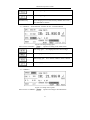
3.2.3 Single step manual test page
Oh the page,press
,the instrument enters charging
14
TH2689/89A Operation manual
step;and press
to tes;finally press
to
return to discharge status.
3.2.3.1 <STEP TEST>
On <MAIN INDEX> page,use direction key to move cursor to“(2)
STEP TEST”,press
to enter <STEP TEST>,there are 2 pages on
<STEP TEST>,shown as figure 3-11:
Figure 3-11(a) STEP TEST page 1
Figure 3-11(b) STEP TEST page 2
※Note:
(1)In CHARGE status, parameter can’t be set,in TEST status, only RANG and
SPEED can be set.
(2)In the status of CHARGE and TEST,press
to return to
discharge status.
(3)TRIG mode is set as BUS、EXT,trigger signal is controlled by external
interface,it is invalid to press
.
15
TH2689/89A Operation manual
3.2.3.2 Instruction of setting parameter
(1)LEV、CC、RANG、SPEED see §3.2.2.3
(2)Trigger mode (TRIG)
Figure 3-12 setup of trigger mode
Move cursor to“TRIG: INT”, operate according to the table below:
Internal auto trigger
Manual trigger
External trigger
※Note:BUS(bus trigger)is set by bus command
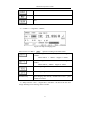
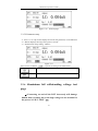
3.2.4 Continues auto test page
On the function page, press
,the instrument performs
a procedure of charge and test;if a capacitor without electricity is connected to
the test terminal, then trigger a procedure of charge and test automatically.
Finally press
to return to discharge status. The function is
suitable for continues manual test status without discharge.
3.2.4.1 <CONT TEST>
On <MAIN INDEX>page,use direction key to move cursor to “(3)
CONT TEST”,and press
to enter <CONT TEST>page,there are
2 pages on <CONT TEST>,shown as the figure 3-13:
16
TH2689/89A Operation manual
图 3-13(a) CONT TEST 第一页选项
图 3-13(b) CONT TEST page 2
※Note:
(1)In CHARGE status, parameter can’t be set,in TEST status, only RANG and
SPEED can be set.
(2)In the status of CHARGE and TEST,press
to return to
discharge status.
3.2.4.2 Set parameter instruction
(1)LEV、CC、RANG、SPEED, see §3.2.2.3
3.2.5 Null test page
3.2.5.1 <NULL> page
On <MAIN INDEX> page,use direction key to move cursor to “(4)
NULL”,and press
page,press
to enter <NULL> page(shown as 3-14).on this
to start null test.
17
TH2689/89A Operation manual
Figure 3-14 Null test page
3.2.5.2 Parameter setup
(1)LEV,CC is only used to display the current test parameter, no modification
(2)RANG displays the range in the process of null.
(3)Null function setup setting(OPEN)
Move cursor to“OPEN:
Figure 3-15
ON”,operate according to the table below:
Turn on null function
Turn off null function
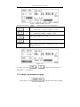
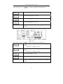
3.2.6 Aluminium foil withstanding voltage test
page
a Connecting on and off the DUT incorrectly will damage
human body seriously due to the high voltage on test terminal in
the process of “W.V. TEST”!!!
18
TH2689/89A Operation manual
The correct connection method is to make the instrument in
the discharging status.
3.2.6.1 <W.V. TEST>
On <MAIN INDEX>,use direction key to move cursor to“(5) W.V.
TEST”,and press
to enter <W.V. TEST> page(shown as figure
3-16).
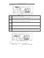
2
1
Figure 3-16 W.V. TEST
3.2.6.2 Set parameter and instruction of displayed parameter
Vf: rated leather withstanding voltage.
CC:W.V charging current.
Tend: Tr+ identificated withstanding voltage time.
ChgTD: set charge high limit time.
Tr:display the rising time when test voltage reaches 90%Vf.
Vt:display the voltage when test time reaches Td(Tend);
1:monitor the voltage value at output terminal;
2:display the final tested voltage and time when test ends;
3:if the test is cancelled in the process,only press
to enter
discharge status at anytime.
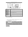
3.2.6.3 Parameter setting
(1)Rated feather withstanding voltage(Vf):range 1V~800V(TH2689)/ 1V~
19
TH2689/89A Operation manual
500V(TH2689A)
Figure 3-17
Move cursor to“Vf: 100.0V”,operate according to the table below:
Coarse turning,from small to large:
6.3→10.0→16.0→25.0→35.0→50.0→63.0→100.0→160.0→200.0→250.0→350.0→
400.0→450.0→500.0(→550.0→600.0→630.0→800.0)
Coarse turning,from large to small:
6.3←10.0←16.0←25.0←35.0←50.0←63.0←100.0←160.0←200.0←250.0←350.0←
400.0←450.0←500.0(←550.0←600.0←630.0←800.0)
Fine turning,stepped is +0.1V
Fine turning,stepper is -0.1V
Numer
ic key
Input rated feather withstanding voltage value directly, and press ENTER to confirm
(2)W.V charge current(CC),range 0.5mA~IMAX
Figure 3-18 charge current setting
※Note:
Max. charge current in limited by power,according to P=UI
Imax = P / VMAX
— — —(P = 65W,VMAX see Vf)
20
TH2689/89A Operation manual
Move cursor to “CC: 15.0mA”,operate according to the table below:
Coarse turning. Stepper is +5.0mA;
Coarse turning. Stepper is -5.0mA;
Fine turning. Stepper is +0.5 mA;
Fine turning. Stepper is -0.5 mA;
Numeric key
Input W.V charge current value directly, press ENTER to
confirm
(3)W.V test time(Td)
,range 0Sec~600Sec
Figure 3-19
Move cursor to“Td:Tr+ 30S”,operate according to the table below:
Coarse turning. When set value ≥100Sec , stepper is
+100Sec;
Otherwise,stepper is +10S;
Coarse turning. When set value ≥100Sec , stepper is
-100Sec;
Otherwise,stepper is -10Sec;
Fine turning. Stepper is +1Sec;
Fine turning. Stepper is -1Sec;
Numeric key
Input W.V charge current value directly, press ENTER to
confirm
(4)W.V charge time high limit(ChgTd),range 5Sec~600Sec
21
TH2689/89A Operation manual
Figure 3-20 charge time high limit setup
Move cursor to “ChgTd: 50S”,operate according to the table below:
Coarse turning. Stepper is +30Sec;
Coarse turning. Stepper is -30Sec;
Fine turning. Stepper is +5Sec;
Fine turning. Stepper is -5Sec;
Numeric key
Input W.V charge current value directly, press ENTER to
confirm
3.2.6.4 <W.V. TEST> notes
The correct method of cancelling test:when the instrument is in the status
of discharge, the DUT can be connected on and off.
Press
, the instrument is in the status of
discharge, now the DUT can be connected off;when the
DUT is connected, the instrument should be in the status
of discharge .
22
TH2689/89A Operation manual
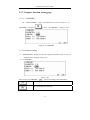
3.2.7 Compare function setting page
3.2.7.1 <COMPARE>
On <MAIN INDEX> page,use direction key to move cursor to“(6)
COMPARE”,and press
to enter <COMPARE>(shown as 3-21).
Figure 3-21 COMPARE
3.2.7.2 Parameter setting
(1)PARAMETER:display the current compare parameter mode, it can’t be
modified here, if modify see §3.2.9.1 。
(2)(COMPARE)
Figure 3-22
Move cursor to“COMPARE: ON”,operate according to the table below:
Turn on comparator function
Turn off comparator function
(3)(UPPER)
23
TH2689/89A Operation manual
Figure 3-23
Turn on the comparator upper limit function
Turn off the comparator upper limit function
Numeric key
Input comparator upper limit function value directly
(4)(LOWER)
Refer to comparator upper limit setting.
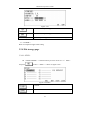
3.2.8 File storage page
3.2.8.1 <FILE>
On <MAIN INDEX>,use direction key to move cursor to“(7) FILE”,
and press
to enter <FILE>(shown as figure 3-24).
Figure 3-24 FILE
Load file
Save file
24
TH2689/89A Operation manual
Rename file
Delete file
3.2.8.2 File storage operation
(1)0~9 files can be saved,No. 10 file is the default file which is used to
recover the default status.
(2)“----------”means there is no corresponding file storage
(3)Stored file flowchart
Press
,page turns to file input,shown as figure 3-25:
Figure 3-25 Input file name
After inputting file name,press
to confirm,the page displays saving
processing table,shown as figure 3-26:
Figure 3-26
After saving,page displays as figure 3-27(if file name is“A”):
25
TH2689/89A Operation manual
Figure 3-27
3.2.9 System configuration page
Press
,enter<SYSTEM CONFIG>,there are 3 pages ,
shown as figure 3-28:
Figure 3-28(a)SYSTEM CONFIG page 1
Figure 3-28(b)SYSTEM CONFIG page 2
26
TH2689/89A Operation manual
Figure 3-28(c)SYSTEM CONFIG page 3
3.2.9.1 System parameter setting
(1)(PARAMETER),default is L.C.
Figure 3-29
Move cursor to “PARAMETER”:
Parameter is set as(I.R.)
Parameter is set as(L.C.)
(2)(KEY LOCK),default is OFF
Figure 3-30
Move cursor to“KEY LOCK”:
Turn on key lock,when the page is switched to test
function
page , the
former
softkey
zone
displays“KeyLock” which means key is locked. If unlock
the function,it is necessary to input(PASS WORD),refer
to the instruction of PASS WORD on page 3.
Turn off key lock
27
TH2689/89A Operation manual
(3)(CHG TIME),default is Vm=Vs
Figure 3-31
Move cursor to “CHG
TIME”:
Calculate the charge time fron Vm=Vs
Calculate the charge time from Vm=0V
※According to JIS(Japanese Industrial Standards,
),after the DUT is charged to
the rated working voltage,calculate the charge time, so please select Vm=Vs in
order to meet the rules of JIS.
(4)Switch range interval time(RNG DWELL),range 0.0Sec~9.9Sec,default
is 0.0Sec
Figure 3-32
Move cursor to “RNG DWELL”:
+0.1Sec
-0.1Sec
Numeric key
Input switch range interval time directly, default unit is
Sec
(5)Test average time(AVERAGE),range 1~8,default is 1。
28
TH2689/89A Operation manual
Figure 3-33
Move cursor to “AVERAGE”:
+1
-1
Numeric key
Input average time directly
(6)(BEEP SET),default is ON
Figure 3-34
Move cursor to “BEEP SET”:
Sound
Silence
(7)(BEEP MODE),default is FAIL
Figure 3-35
29
TH2689/89A Operation manual
Move cursor to“BEEP MODE”:
Alarm when the test result is pass in COMPARE
Alarm when the test result is fail in COMPARE
Turn to the second page of SYSTEM
CONFIG
(8)HANDLE(HDL SET),default is ON
Figure 3-36 HANDLER
Move cursor to “HDL SET”:
HANDLER interface is allowed
HANDLER interface is forbidden
Turn back to the first page of SYSTEM CONFIG
(9)HANDLER(HDL MODE),default is CLEAR
Figure 3-37 HANDLER
Move cursor to“HDL MODE”:
30
TH2689/89A Operation manual
CLEAR mode,when using HANDLER interface,before
testing,clear out the output signal of last test(PASS or
FAIL)
HOLD mode,when using HANDLER,the output signal
(PASS or FAIL)will be changed until the next result
being changed
(10)(TRIGDELAY),range 0~9999mSec,default is 0mSec
Figure 3-38
Move cursor to “TRIGDELAY”:
Numeric key
Input delay time directly,default value is mSec
(11)(TRIG EDGE),default is FALLING
Move cursor to“TRIG
Figure 3-39
EDGE”:
(FALLING)
(RISING)
(12)(BUS MODE),default is RS232
31
TH2689/89A Operation manual
Figure 3-40 Bus mode setting
Move cursor to“BUS
MODE”:
Use GPIB interface
Use RS232 interface
No bus control
(13)(GPIB ADDR),range 00~30,default is 08
Figure 3-41
Move cursor to“GPIB
ADDR”:
+1
-1
Numeric key
Input GPIB address directly
(14)(BAUD RATE),6 selections,default is 19200
32
TH2689/89A Operation manual
Figure 3-42(a)
Move cursor to“BAUD
Figure 3-42(b)
RATE”:
Switch as figure 3-42
Select 600,1200,4800,9600,19200,28800 baud rate
……
Turn to the third page of SYSTEM CONFIG
(15)(EOS CODE),default is ASCII code 0AH
Figure 3-43
33
TH2689/89A Operation manual
Move cursor to“EOS
CODE”:
The selection of Eos data is ended with 0AH
The selection of Eos data is ended with 0DH
The selection of Eos data is ended with 0DH0AH
Back to the second page of SYSTEM CONFIG
(16)(LINE FREQ),default is 50Hz
Move cursor to “LINE
Figure 3-44
FREQ”:
Power frequency is 50Hz
Power frequency is 60Hz
(17)EXTV DISP,default is OFF
Figure 3-45 EXTV DISP
Move cursor to“EXTV DISP”:
34
TH2689/89A Operation manual
When waiting for the external trigger signal, the tested
voltage is displayed immediately
When waiting for the external trigger signal, the tested
voltage is not displayed
(18)(PASS WORD),the default password is “2689”
Move cursor to “PASS
Figure 3-46
WORD” , if you modify the password, press
,then you should input your old password,shown as figure 3-47:
Figure 3-47
Press
to cancel the modification , use numeric key to input
password,the press
to confirm,if you input correctly, you can
input the new password shown as figure 3-48:
35
TH2689/89A Operation manual
Figure 3-48
Use numeric key to input new password, press
reinput the new password can be saved.
Figure 3-49
(19)(CONTRAST),range 0~31,the default is 15
Figure 3-50
Move cursor to“CONTRAST”:
+1
-1
(20)(KEY BEEP),the default is ON
Figure 3-51
36
to confirm and
TH2689/89A Operation manual
Move cursor to“KEY BEEP”:
Sound
No sound
37
TH2689/89A Operation manual
Chapter 4 Test performance
4.1(L.C./I.R. TEST)
4.1.1 Parameter
Leakage current test:L.C.(Leakage Current),I.R.(Isolated Resistance)
4.1.2 Test signal
Test voltage
LEV = 1.0V ~ 100V,resolution is 0.1V
= 101V ~ VMAX,resolution is 1V; ±(0.5%+0.2V)
Charge current
LEV ≤ 100V:0.5 mA ~ 500 mA,resolution is 0.5 mA
> 100V:0.5 mA ~ IMAX,resolution is 0.5 mA;
±(3%+0.05mA)
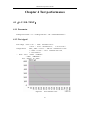
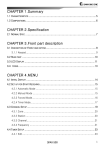
※ Note:VMAX = 800V;(TH2689)
= 500V;(TH2689A)
IMAX = P/LEV;P = 50VA
Figure 4-1
IMAX and LEV curve
38
TH2689/89A Operation manual
4.1.3 Basic accuracy
L.C.---------------±(0.3%+0.05uA)
4.1.4 Display range
L.C.---------------0.000uA~20.00 mA
I.R.---------------0.01kΩ~99.99GΩ
4.1.5 Test time
Parameter
Fast
Medium
Slow
L.C.
53mSec
70mSec
139mSec
I.R.
53mSec
70mSec
139mSec
※Test condition is range hold,trigger mode is EXT,external trigger(EXTV DISP)displays
OFF。
4.1.6
(NULL)
Clear out the leakage current in the whole return circuit.
4.2(W.V. TEST)
4.2.1 Test parameter
Rising time Tr
Feather withstanding voltage Vt
unit:Sec
unit:V
4.2.2 Test signal
Charge current
4.2.3
0.5 mA ~ 80 mA;(TH2689)
0.5 mA ~ 130 mA;(TH2689A)
step 0.5mA
Display range
Tr --------------- 110mSec~600Sec
39
TH2689/89A Operation manual
Vt --------------- 1.0V~VMAX
VMAX = 800V(TH2689)
= 500V(TH2689A)
40
TH2689/89A Operation manual
Chapter 5 Remote Control
TH2689 has the RS232C serial interface and the parallel GPIB (optional) interface. Both interfaces
can be used to remotely control TH2689, but they can not be used at the same time. The two
interfaces share the same program commands, but they have different hardware configurations and
different communication protocols. This chapter provides the information about the two interfaces
and how to use the interfaces.
5.1 RS232C Interface Introduction
The RS232C interface can be used to remotely control the TH2689, and all operations from the
front panel can be performed by a computer via the serial interface.
5.1.1 RS232C connection
RS232C Standard now is widely used as the serial communication standard. RS232 stands for
Recommend Standard number 232 and C is the latest revision of the standard. The serial ports on
most instruments use a subset of the RS-232C standard. The full RS-232C standard specifies a
25-pin "D" connector of which 22 pins are used. Most of these pins are not needed for normal serial
communications, and the common RS232 signals are listed as follows.
41
TH2689/89A Operation manual
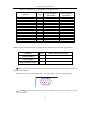
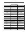
Table 5-1 Definition of common RS232 serial interface pin
25 Pin Connector
9 Pin Connector
Pin Number
Pin Number
RTS
4
7
Clear To Send
CTS
5
8
Data Set Ready
DSR
6
6
Data Carrier Detect
DCD
8
1
Data Terminal Ready
DTR
20
4
Transmitted Data
TXD
3
3
Received Data
RXD
2
2
Signal Ground Common
GND
7
5
Function
Code
Request To Send
TH2689 only uses the smallest subset of the RS232C standard, the signal are listed as follows.
Function
Code
9 Pin Connector Pin Number
Transmitted Data
TXD
3
Received Data
RXD
2
Signal Ground Common
GND
5
LNote:The definition of serial interface pin is basically the same as that of the connector of
standard 9-core RS232C.
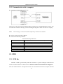
RS232C connecter uses 9 core DB jacket,the order of pin is shown as the figure below:
5 4 3 2 1
9 8 7 6
Warning:please turn off the power when connecting on or off the connecter to avoid
electrical shock;
!
42
TH2689/89A Operation manual
5.1.2 Communication with a computer
Diagram of connection to a controller:
There may be the same between TH2689’s RS232 interface and a standard RS232C interface. You
can make the connection cable by yourself according the diagram or order one from our company.
Note:
Pin 4 and 6, pin 7 and 8 are shorted respectively at the end of controller.
Firstly, set the bus mode as RS232
Main serial interface parameter
Transmitted mode
Baud Rate
Data Bits
Stop Bits
Calibration
End of Sequence
Connection mode
Connecter
Serial Interface Specifications
Dual asynchronous communication including start and stop
bit
Pre-set 19200 bps
8 BIT
1 BIT
None
NL(ASCII code 10)
Software
DB9
5.2 GPIB
5.2.1 GPIB Bus
IEEE488(GPIB)general-used parallel bus interface is a general intelligent instrument bus
interface standard. IEEE is the abbreviation of Institute of Electrical and Electronics Engineers,
488is the standard number. Through this interface, the communication between computer and other
43
TH2689/89A Operation manual
intelligent instruments can be collected, as well as an auto test system can be composed
conveniently with other test instrument. In the same bus, many test instruments can be connected
simultaneously. In this instrument, the IEEE488.2standard is adopted, and the interface board can
be selected and bought by user. The control instruction system is open, so user can use the
computer operation interface, also can write a program based on this system to achieve the goal.
The control instruction system supports most function that is to say; all function can be operated on
controlling the computer to realize the remote control.
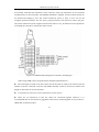
Figure 5-3 GPIB Structure Diagram of Connector Assembly/pin
When using GPIB system, the points below should be paid attention to:
z
The total length of cable in one bus system must be less than or equal to two meters times the
number of devices connected on the bus (the GPIB controller counts as one device) and the total
length of cable must not exceed 20 meters.
z
A maximum of 15 devices can be connected in one bus system.
z
There are no restrictions on how the cables are connected together. However, it is
recommended that no more than four piggyback connectors be stacked together on any one device.
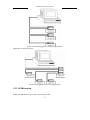
GPIB cable connection mode-1
44
TH2689/89A Operation manual
Figure 5-4 Double-piggyback Connector Superposition
GPIB cable connection mode-2:
Figure 5-5 4-piggyback Connector Superposition
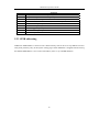
5.2.2 GPIB function
TH2689's GPIB functions are listed in the following table.
45
TH2689/89A Operation manual
Code
SH1
AH1
T3
L3
RL1
DC1
DT1
C0
E1
Function
Complete Source Handshake capability
Complete Acceptor Handshake capability
Basic Talker; Talk-Only; unaddressed if MLA; no serial poll
Basic Listener; unaddressed if MTA; no Listen Only
Remote/Local capability
Device Clear capability
Device Trigger capability
No Controller capability
Drivers are open-collector
5.2.3 GPIB addressing
TH2825A's GPIB address is stored in non-volatile memory and can be set to any address from 0 to
30 by front panel key entry in the System Config page. When TH2825A is shipped from the factory,
the default GPIB address is 8. For more information, refer to “§3.2.9GPIB Address”.
46
TH2689/89A Operation manual
Chapter 6 Command reference
There are two types of command:GPIB sharing command and SCPI(standard command
ofprogrammable instrument) command. GPIB sharing command is defined by IEEE488.2-1987,
these commands are available in all devices, but TH2689 dosen’t support all sharing commands.
SCPI command is a tree structure.
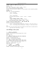
6.1 Sharing command instruction
1. *RST
Function:restart the instrument.
2. *IDN?
Function:query the information about 4 field( separated by comma)。
Return value:company,model, version number
Example : TH2689 is“TongHui,2689,800,Ver0.1 2008”;
TH2689A is“TongHui,2689A,500,Ver0.1 2008”;
3. *TRG
Function:in the bus trigger mode,
4. *SAV
Function:Save file
Parameter:<numeric_value>
Instruction:<numeric_value> is the file ordinal number from 0~9
Example:
*SAV 1
Attention:There is no clue when the existed file records are covered.
5. *RCL
Parameter:<numeric_value>
Function:Load the existed file records
Instruction:<numeric_value> is the file ordinal number from 0~9.
Example:
*RCL 1
47
TH2689/89A Operation manual
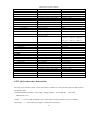
6.2 SCPI Order structure
Figure 6-1 SCPI command table
Command
ABORt
CALCulate
:LIMit
:FORMat
:BEEPer
:CONDition
:STATe
:CLEar
:FAIL?
:STATe
:UPPer
[:DATA]
:LOWer
[:DATA]
:ONOFf
:NULL
[:IMMediate]
:DATA?
:STATe
DISPlay
:STATe?
:LCTest
:WVTest
LCTest
:SOURce
:VOLTage
:CURRent
:CONFigure
:FUNCtion
:SPEed
:RANGe
:AUTO
:CHGTime
:DWELl
:MEASure
:STATe?
:FETCh?
:IR?
:LC?
:VMON?
Command
Parameter
Return value
[无查询]
{IR | LC}
{IR | LC}
{FAIL | PASS}
{OFF | ON | 0 | 1}
[only for query]
{OFF | ON | 0 | 1}
{FAIL | PASS}
{0 | 1}
[no query]
{0(PASS)| 1(FAIL)}
{0 | 1}
{ <numeric_value> | MAX | MIN}
<numeric_value> | OFF
{ <numeric_value> | MAX | MIN}
{0 | 1 | 2 | 3}
<numeric_value> | OFF
{0 | 1 | 2 | 3}
[only for query]
{OFF | ON | 0 | 1}
[no query]
{NR3},{NR3},{NR3},{NR3},
{NR3}
{0 | 1}
[only for query]
{LCTEST | WVTEST | NULL |
MAIN | SYSTEM}
[no query]
[no query]
{ <numeric_value> | MAX | MIN}
{ <numeric_value> | MAX | MIN}
<numeric_value>
<numeric_value>
{SEQ | STEP | CONT}
{FAST | MEDium | SLOW}
{<range> | MAX | MIN}
{OFF | ON | 0 | 1}
{ <numeric_value> | MAX | MIN}
{ <numeric_value> | MAX | MIN}
{SEQ | STEP | CONT}
{FAST | MEDIUM | SLOW}
<range>
{0 | 1}
<numeric_value>
<numeric_value>
[only for query]
[only for query]
{CHG | TEST | DCHG}
{0(OK) | 1(ERROR)},
{NO | PASS | HIGH | LOW }
{NR3}
{NR3}
{NR3}
[only for query]
[only for query]
[only for query]
Parameter
48
Return value
TH2689/89A Operation manual
WVTest
:SOURce
:VOLTage
:CURRent
:CONFigure
:TEND
:CHGTEND
:MEASure
:STATe?
:TRise?
:VTerminate?
:TEnd?
:VEnd?
[:DATA]
:DATA?
:DATA:POINts
TRIGger
[:IMMediate]
:SOURce
:DELay
:EDGE
SYSTem
:BEEPer
[:IMMediate]
:STATe
:LFRequency
:HANDler
:STATe
:CONTrast
:RANGEDwell
:AVErage
:PRESet
:ERRor?
{ <numeric_value> | MAX | MIN}
{ <numeric_value> | MAX | MIN}
<numeric_value>
<numeric_value>
{ <numeric_value> | MAX | MIN}
{ <numeric_value> | MAX | MIN}
<numeric_value>
<numeric_value>
[only for query]
[only for query]
[only for query]
[only for query]
[only for query]
{CHG | TEST | DCHG}
{NR3}
{NR3}
{NR3}
{NR3}
[only for query]
<start>,<end>
<set1_N>,<set1_T>,<set1_V>;
<set2_N>,<set2_T>,<set2_V>;
……
<setn_N>,<setn_T>,<setn_V>;
<numeric_value>
{INT | MAN | EXTernal | BUS}
{ <numeric_value> | MAX | MIN}
{FALLing | RISIng}
[noquery]
{INT | MAN | EXT | BUS}
<numeric_value>
{FALL | RISI}
{OFF | ON | 0 | 1}
{50 | 60}[HZ]
{CLEAR | HOLD}
{OFF | ON | 0 | 1}
<numeric_value>
{ <numeric_value> | MAX | MIN}
{ <numeric_value> | MAX | MIN}
[only for query]
[no query]
{0 | 1}
{50 | 60}[HZ]
{CLEAR | HOLD}
{0 | 1}
<numeric_value>
<numeric_value>
<numeric_value>
[no query]
<numeric_value>,<string>
6.2.1 Order structure instruction
The top of tree structure order is root command, or called root. The specified path can help reach to
the bottom order.
Command ending character:order input ending character, for example NL(line break
,ASCIIcode is 10)。
Colon(:):Colon is the command level, which means entering the next level of command.
Semicolon(;
):semicolon means begin a mulNotele command.
49
TH2689/89A Operation manual
interrogation(?):interrogation means query。
Comma(,):Comma is break of multi-parameter
Space( ):Space is the break of command and parameter
Quote mark(‘ ’):Single quotes means the content quoted by original sample, and the command
analyze program doesn’t process on it
Asterisk(*)
:The command after asterisk is the sharing command.
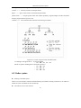
Figure 6-1 Correct Usage of Colon and Semicolon
According to the figure above,if send command
:AA:BB:EE;FF;GG
Which is equal to sending three commands as below?
:AA:BB:EE
:AA:BB:FF
:AA:BB:GG
6.3 Order syntax
z
Sharing command syntax
There is no tree structure of SCPI command sharing command in sharing command, so no matter in
which level, the command can be sent directly.
z
The letters are not case sensitive
50
TH2689/89A Operation manual
z
Ending character
There are three kinds of ending character:
[CARRIAGE RETURN](0Dh),
(0Ah)and [CARRIAGE RETURN](0Dh)+[NEW LINE](0Ah).
6.4 SCPI order instruction
6.4.1 ABORt order system
1.
:ABORt
parameter:None
Return value:None
Function:Breakout the processing system instantly, and reset the trigger
6.4.2 CALCulate order system
1. :CALCulate:LIMit:FORMat {IR | LC}
Function:set or query the current test main parameter
Parameter:{IR | LC}
Return value:{IR | LC}
Instruction:IR
the parameter is the resistance value
LC
the parameter is the current value
2. :CALCulate:LIMit:BEEPer:STATe { OFF | ON | 0 | 1}
Function:set or query the beeper
Parameter:{ OFF | ON | 0 | 1}
Return value:{ 0 | 1 }
instruction:OFF | 0
turn on beeper
ON | 1
turn off beeper
3. :CALCulate:LIMit:BEEPer:CONDition {FAIL | PASS}
Function:set or query the compare output of beeper
Parameter:{FAIL | PASS}
Return value:{FAIL | PASS}
Instruction:FAIL
Alarm when comparator result is FAIL
PASS
Alarm when comparator result is PASS
4. :CALCulate:LIMit:CLEar
Function:Delete:CALCulate:LIMit:FAIL?command
Parameter:none
Return value:no
5. :CALCulate:LIMit:FAIL?
51
[NEW LINE]
TH2689/89A Operation manual
Function:send the comparator result
Parameter:none
Return value:{ 0 | 1 }
Instruction:0
comparator result is FAIL
1
comparator result is PASS
6. :CALCulate}:LIMit:STATe { OFF | ON | 0 | 1}
Function:set or query if set up comparator function
Parameter:{ OFF | ON | 0 | 1}
Send-back vale:{ 0 | 1 }
Instruction:OFF | 0
turn off comparator function
ON | 1
turn on comparator function
7. :CALCulate:LIMit:UPPer[:DATA] {<numeric_value> | MIN | MAX}
Function:set or query the upper limit value of comparator function parameter,format is <NR3>
Parameter:{<numeric_value> | MIN | MAX}
Return value:numeric_value | OFF
Instruction:OFF
8. :CALCulate:LIMit:LOWer[:DATA] {<numeric_value> | MIN | MAX}
Function:set or query the low limit value of comparator function parameter,format is <NR3>
Parameter:{<numeric_value> | MIN | MAX}
Return value:numeric_value | OFF
Instruction:OFF
9. :CALCulate:LIMit:ONOFf {0 | 1 | 2 | 3|4|5}
Function:set or query the selection of comparator function
Parameter:{0 | 1 | 2 | 3}
Return value:{0 | 1 | 2 | 3}
Instruction:0
turn off comparator
1
turn on comparator upper limit function
2
turn on comparator low limit function
3
turn on comparator upper and low limit function
4
turn on comparator low limit function
5
turn on comparator low limit function
10. :CALCulate:NULL[:IMMediate]
Function:excecute open correction of each bin(20mA、2mA、200uA、20uA and 2uA)
Parameter:none
Return value:none
11. :CALCulate:NULL:DATA?
Function:query open correction value of each bin(20mA、2mA、200uA、20uA and 2uA)
Parameter:none
Return value:numeric_value,numeric_value,numeric_value,numeric_value,numeric_value
12. :CALCulate:NULL:STATe { OFF | ON | 0 | 1}
Function:set or query if set on open correction function
Parameter:{ OFF | ON | 0 | 1}
Return value:{ 0 | 1 }
Instruction:OFF | 0
turn off open correction function
ON | 1
turn on open correction function
52
TH2689/89A Operation manual
6.4.3 DISPlay order system
1. :DISPlay:STATe?
Function:query the currently-displayed function page
Parameter:none
Return value:{LCTEST | WVTEST | NULL | MAIN | SYSTEM}
2. :DISPlay:LCTest
Function:switch function page as LC TEST
Parameter:none
Return value:none
3. :DISPlay:WVTest
Function:switch function page as WV TEST
Parameter:none
Return value:none
6.4.4 LCTest order system
1. :LCTest:SOURce:VOLTage {<numeric_value> | MIN | MAX}
Function:set or query the test voltage of LC/IR function
Parameter:{<numeric_value> | MIN | MAX}
Return value:numeric_value
Instruction:MIN
1V
MAX
800V(TH2689)
500V(TH2689A)
2. :LCTest:SOURce:CURRent {<numeric_value> | MIN | MAX}
Function:set or query the charge current of LC/IR function
Parameter:{<numeric_value> | MIN | MAX}
Return value:numeric_value
Instruction:MIN
0.5mA
MAX
500.0mA(LEV ≤ 100V)
PMAX / LEV(PMAX=50W)
3. :LCTest:CONFigure:FUNCtion {SEQ | STEP | CONT}
Function:set or query the test mode of LC/IR function
Parameter:{SEQ | STEP | CONT}
Return value:{SEQ | STEP | CONT}
4. :LCTest:CONFigure:SPEed {FAST | MEDium | SLOW}
Function:set or query the test speed of LC/IR function
Parameter:{FAST | MEDium | SLOW}
Return value:{FAST | MEDium | SLOW}
5. :LCTest:CONFigure:RANGe {<numeric_value> | MIN | MAX}
Function:set or query range bin
Parameter:{<numeric_value> | MIN | MAX}
Return value:numeric_value
53
TH2689/89A Operation manual
Instruction:numeric_value is 4(20mA)、3(2mA)、2(200uA)
、1(20uA)及 0(2uA)
MIN 为 2uA
MAX 为 20mA
6. :LCTest:CONFigure:RANGe:AUTO { OFF | ON | 0 | 1}
Function:set or query if set on auto switching bin mode
Parameter:{OFF | ON | 0 | 1}
Return value:{ 0 | 1}
Instruction:OFF | 0
select range bin manually
ON | 1
select range bin automatically
7. :LCTest:CONFigure:CHGTime {<numeric_value> | MIN | MAX}
Function:set or query the charge time
Parameter:{<numeric_value> | MIN | MAX}
Return value:numeric_value
Instruction:numeric_value 为 0Sec~999Sec
MIN is 0Sec
MAX is 999Sec
8. :LCTest:CONFigure:DWELl {<numeric_value> | MIN | MAX}
Function:set or query the delay time value of SEQ test mode
Parameter:{<numeric_value> | MIN | MAX}
Return value:numeric_value
Instruction:numeric_value 为 0.2Sec~999.0Sec
MIN is 0.2Sec
MAX is 999.0Sec
9. :LCTest:MEASure:STATe?
Function:query the current test status
Parameter:none
Return value:{CHG | TEST | DCHG}
10. :LCTest:MEASure:FETCh?
Function:query test result
Parameter:none
Return value:{0(OK)| 1(ERROR)},{NO | PASS | HIGH | LOW}
Instruction:0
not in TEST status, or in TEST not over the range
1
select a unsuitable range, can not obtain a correct test result
NO
not use comparator to make comparision
PASS | HIGH | LOW
comparator performs compare result
11. :LCTest:MEASure:IR?
Function:query IR value of test result
Parameter:none
Return value:numeric_value,format is <NR3>,unit is OHM
12. :LCTest:MEASure:LC?
Function:query LC value of test result
Parameter:none
Return value:numeric_value,format is <NR3>,unit is AMP
13. :LCTest:MEASure:VMON?
Function:query the voltage test value
Parameter:none
54
TH2689/89A Operation manual
Return value:numeric_value,format is <NR3>,unit is VOLT
6.4.5 WVTest order system
1. :WVTest:SOURce:VOLTage {<numeric_value> | MIN | MAX}
Function:set or query the test voltage of WV function
Parameter:{<numeric_value> | MIN | MAX}
Return value:numeric_value
Instruction:MIN
1V
MAX
800V(TH2689)
500V(TH2689A)
2. :WVTest:SOURce:CURRent {<numeric_value> | MIN | MAX}
Function:set or query charge current of WV function
Parameter:{<numeric_value> | MIN | MAX}
Return value:numeric_value
Instruction:MIN
0.5mA
MAX
PMAX / VfMAX(PMAX=65W,VfMAX)
3. :WVTest:CONFigure:TEND {<numeric_value> | MIN | MAX}
Function:set or query the test ending time of WV function
Parameter:{<numeric_value> | MIN | MAX}
Return value:numeric_value
Instruction:MIN
0Sec
MAX
600Sec
4. :WVTest:CONFigure:CHGTEND {<numeric_value> | MIN | MAX}
Function:set or query the Max. charging time of WV function
Parameter:{<numeric_value> | MIN | MAX}
Return value:numeric_value
Instruction:MIN
5Sec
MAX
600Sec
5. :WVTest:MEASure:STATe?
Function:query the current test status
Parameter:none
Return value:{CHG | TEST | DCHG}
6. :WVTest:MEASure:TRise?
Function:query the rising time when test voltage reaches 0.9Vf(working voltage)
Parameter:none
Return value:numeric_value,format is <NR3>,unit is Sec
7. :WVTest:MEASure:VTerminate?
Function:query the test voltage value when test time reaches to Tend
Parameter:none
Return value:numeric_value,format is <NR3>,unit is V
8. :WVTest:MEASure:TEnd?
Function:query the total test time of WV:rising time(Tr)+test time
Parameter:none
Return value:numeric_value,format is<NR3>,unit is Sec
55
TH2689/89A Operation manual
9. :WVTest:MEASure:VEnd?
Function:query the test voltage value when WV ends.
Parameter:none
Return value:numeric_value,format is <NR3>,unit is V
10. :WVTest:MEASure:DATA[:DATA]?
Function:return the data saved in buffer area,and the number of data is defined by POINTs
command
Parameter:none
Return value:query the responded data is
<set1>:first group
<set2>:second group
‥
<setn>:the last group
Each group includes parameter:<point>,<time>,<voltage>
Where
<point>is number,format is <NR1>,
<time> is time data,format is <NR3>,unit is S
<voltage>is voltage data,format is <NR3>,unit is V
11. :WVTest:MEASure:DATA:POINts <start>,<end>
Function:set or query the amount of data
Parameter: set the amount of returned data, where
<start>:set the start amount of returned data,set range as 1~220(pre-set value is 1)
<end>:set the ending amount of returning data,set range as 1~220(pre-set value is
220)
Return value:query the amount of data saved in buffer area. If return value is 0, which means no
data saved, return value format is <NR1>
6.4.6 TRIGger order system
1. :TRIGger[:IMMediate]
Function:set on test function when the trigger mode is(BUS)
Parameter:none
Return value:none
2. :TRIGger:SOURce {INT | MAN | BUS | EXTernal}
Function:set or query trigger mode
Parameter:{INT | MAN | BUS | EXTernal}
Return value:{INT | MAN | BUS | EXTernal}
3. :TRIGger:DELay {<numeric_value> | MIN | MAX}
Function:set or query the delay time of external trigger source
Parameter:{<numeric_value> | MIN | MAX}
Return value:numeric_value
Instruction:MIN
0mSec
MAX
9999mSec
4. :TRIGger:EDGE {FALL | RISI}
Function:set or query the external trigger signal mode
56
TH2689/89A Operation manual
Parameter:{FALL | RISI}
Return value:{FALL | RISI}
Instruction:FALL
fall trigger
RISI
rise trigger
6.4.7 SYSTem order system
1. :SYSTem:BEEPer[:IMMediate]
Function:alarm once
Parameter:none
Return value:none
2. :SYSTem:BEEPer:STATe {OFF | ON | 0 | 1}
Function:set or query if beeper has been set on
Parameter:{OFF | ON | 0 | 1}
Return value:{ 0 | 1 }
Instruction:OFF | 0
turn off beeper
ON | 1
turn on beeper
3. :SYSTem:LFRequency {50 | 60}
Function:set or query the power frequency.
Parameter:{50 | 60 }
Return value:{50 | 60 |,unit is Hz
4. :SYSTem:HANDler {CLEAR | HOLD}
Function:set or query the clear mode of HANDLER interface
Parameter:{CLEAR | HOLD}
Return value:{CLEAR | HOLD}
Instruction:CLEAR
clear the last test result before testing
HOLD
the test result holds unitl the next test result changes
5. :SYSTem:HANDler:STATe {OFF | ON | 0 | 1}
Function:set or query if set on HANDLER interface
Parameter:{OFF | ON | 0 | 1}
Return value:{ 0 | 1 }
Instruction:OFF | 0
turn off HANDLER interface
ON | 1
turn in HANDLER interface
6. :SYSTem:CONTrast {<numeric_value>}
Function:set or query the contrast of LCD
Parameter:<numeric_value>
Return value:<numeric_value>,0~31
7. :SYSTem:RANGEDwell {<numeric_value> | MIN | MAX}
Function:set or query LC/IR range bin switch delay time
Parameter:{<numeric_value> | MIN | MAX}
Return value:numeric_value
Instruction:MIN
0.0Sec
MAX
9.9Sec
8. :SYSTem:AVErage {<numeric_value> | MIN | MAX }
Function:set or query average time
57
TH2689/89A Operation manual
Parameter:{<numeric_value> | MIN | MAX}
Return value:numeric_value
Instruction:MIN
1
MAX
8
9. :SYSTem:PRESet
Function:reset to preset status
Parameter:none
Return value:none
10. :SYSTem:ERRor?
Function:query the error information
Parameter:none
Return value:numeric_value string
Instruction:numeric_value error code
string
error string
6.5 Error information
Common error table:
Code
String
0
“No error”
-1
“Unknow message”
-2
“Syntax error”
-3
“Parameter error”
-4
“Data type error”
-5
“Data too long”
-6
“Invalid data”
-7
“Suffix error”
-8
“Can’t executed”
-9
“No record”
-10
“Too many errors“
58
TH2689/89A Operation manual
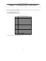
Chapter 7 Sorting interface instruction
When using COMPARE, HANDLER is connected with external device and its connector is 24
core,the instruction of pin is as below.
7.1 HANDLER interface
Pin
1
2
3,20
5-7
4,24
8
9
10
11
12-14
15
16
17
18
19
21
22
23
Figure 7-1 HANDLER interface
Name
/EXT TRIG
/DISCHARGE
/TEST
COM1
X
GND
X
VEXT
VINT
X
/PASS
/CHARGE
/FAIL
/EOT
/HI
/LO
/ACQ
/FAIL_CHARGE
※Note:in figure 7-1,“/”means low level is valid.
59
TH2689/89A Operation manual
7.2 The jumper set on HANDLER board
The jumper on HANDLER board is used to select internal or external power in outputting
signal and controlling signal.
!
warning:
Be sure the power jack has been removed
and operate after internal capacitor is discharged
)Note:In figure 7-2 and 7-1,“N”means the default jumper setting.
Figure 7-2
Jumper
Description
No.
Position
Left
Use internal ground
J901
Right
Use external ground
(N)
Use internal DC voltage source VCC(+5V),set
Left
J901 to left
J902
Right
Use external DC voltage EXV1(5V-24V),set
(N)
J901to right
Figure 7-1
60
TH2689/89A Operation manual
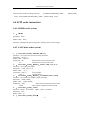
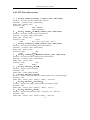
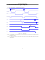
7.3 HANDLER interface signal diagram
(1)when in SEQ.TEST,HANDLER signal diagram
/EXT TRIG
Note 2
/CHARGE
/TEST
/DISCHARGE
/ACQ
/EOT
Note 1
/PASS
/FAIL
/LO
/HI
Figure 7-2 SEQ.TEST
※Note 1:HANDLER is in CLEAR mode,enter test status to clear out the last compare result of
PASS/FAIL signal.
Note 2:confirm how long to enter charge status after receiving /EXT TRIG signal by setting
TRIGDELAY.
61
TH2689/89A Operation manual
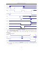
(2)when in STEP TEST,HANDLER interface signal diagram
/EXT TRIG
Note 2
/CHARGE
/TEST
/DISCHARGE
/ACQ
/EOT
/PASS
Note 1
/FAIL
/LO
/HI
Figure 7-3 STEP TEST
※Note 1:When HANDLER is in HOLD mode,comparator result of PASS/FAIL signal is turned
after the next result changes.
Note 2 : when in discharge status , receive /EXT TRIG signal , the instrument charges
automatically.
(3)Charge fail diagram
/CHARGE
/TEST
/DISCHARGE
/FAIL CHARGE
Figure 7-4
※Note :As for the /FAIL CHARGE signal generated by charge failing,clear out the signal in the
next charge
62