1
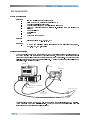
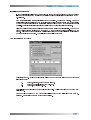
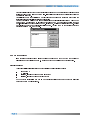
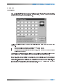
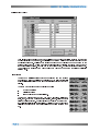
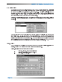
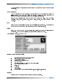
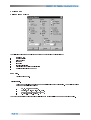
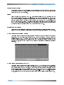
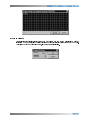
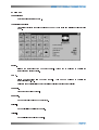
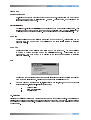
OPERATING MANUAL BARRETT 977 VEHICLE TRACKING SYSTEM © Barrett Communications Pty. Ltd. Version 1.2 BARRETT 977 VEHICLE TRACKING SYSTEM . x OVERVIEW .......................................................................................................................................1 GETTING STARTED ..........................................................................................................................2 System Requirements ...........................................................................................................2 Hardware .................................................................................................................2 Software...................................................................................................................2 Map Data..................................................................................................................2 Setting Up Base Station .........................................................................................................2 Software Installation ..............................................................................................................3 Software Security ..................................................................................................................3 Setting Up Mobiles.................................................................................................................3 Map Registration...................................................................................................................4 Co-ordinate System .......................................................................................................4 Default Map Level ..........................................................................................................4 Image Preparation .........................................................................................................4 Installing the map images ...............................................................................................5 Add to Register...............................................................................................................5 Remove from Register ...................................................................................................6 Display Register.............................................................................................................6 Radio Network Setup.............................................................................................................7 Channel Setup ...............................................................................................................7 Polling List......................................................................................................................8 Icon Library ....................................................................................................................8 Polling Groups ...............................................................................................................9 Poll Times ......................................................................................................................10 Group Settings ...............................................................................................................10 Zone Settings.................................................................................................................11 Global Zones..................................................................................................................11 Quick Poll.......................................................................................................................12 Single Poll ......................................................................................................................12 Follow Only ....................................................................................................................12 Follow & Poll...................................................................................................................12 TRACKING MENU .............................................................................................................................13 Start / End..............................................................................................................................13 Quick Poll ..............................................................................................................................13 Follow....................................................................................................................................13 Playback ...............................................................................................................................13 Map Level..............................................................................................................................14 Area ......................................................................................................................................14 Load/Default Areas................................................................................................................15 Save......................................................................................................................................15 Delete....................................................................................................................................15 Tracking Information..............................................................................................................15 Register.................................................................................................................................15 OPTIONS MENU ...............................................................................................................................16 Options Window ....................................................................................................................16 Show Grid..............................................................................................................................16 Grid Interval...........................................................................................................................16 Tracking Mode.......................................................................................................................17 Tracking Display ....................................................................................................................17 Enable/Disable Track Memory...............................................................................................17 Clear Track Memory ..............................................................................................................17 Polling List .............................................................................................................................17 Polling Groups.......................................................................................................................18 Playback Interval ...................................................................................................................17 Follow when Requested ........................................................................................................18 Follow when Polled................................................................................................................18 Follow All ...............................................................................................................................18 Show Distance ......................................................................................................................18 Set and Clear XY- Shift ..........................................................................................................18 Mobile Icon Size ....................................................................................................................19 Show Mobile Icon ID ..............................................................................................................19 Show Mobile Icon Description................................................................................................19 Show All Mobile Labels ..........................................................................................................19 SAFETY MENU..................................................................................................................................20 Collision Detection.................................................................................................................20 ZONES ..............................................................................................................................................20 Zone Management ................................................................................................................21 Create Zones.........................................................................................................................22 Display All Zones ...................................................................................................................22 Hide All Zones .......................................................................................................................23 Event Log..............................................................................................................................23 Clear Log ..............................................................................................................................23 Print Log ...............................................................................................................................24 Display Position from Log File ..............................................................................................24 WAYPOINTS MENU ..........................................................................................................................25 Show Waypoints....................................................................................................................25 Veiw Waypoints .....................................................................................................................25 Move .....................................................................................................................................25 Create ...................................................................................................................................25 Create at Current Location.....................................................................................................26 Delete....................................................................................................................................26 Enable Proximity Checking....................................................................................................25 Mobile Assignment (Proximity Checking)...............................................................................26 Mobile Assignment (Proximity PAGECALL)...........................................................................26 Proximity Distance.................................................................................................................27 TELEMETRY MENU ..........................................................................................................................28 Search...................................................................................................................................29 Options..................................................................................................................................29 FILE MENU ......................................................................................................................................30 Print Setup.............................................................................................................................30 Exit .......................................................................................................................................30 RADIO MENU ....................................................................................................................................31 Transceiver Functions ...........................................................................................................31 Current Transceiver Settings .................................................................................................31 VIEW MENU ......................................................................................................................................33 Refresh Current Map .............................................................................................................33 Zoom In .................................................................................................................................33 Zoom Out ..............................................................................................................................33 Pan .......................................................................................................................................33 Grey Scale.............................................................................................................................33 Colour Palette........................................................................................................................33 SETUP ...............................................................................................................................................35 GPS Co-ordinate Conversion ................................................................................................35 Communications ...................................................................................................................35 Auto Tracking Start ................................................................................................................35 UTC OFFSET.....................................................................................................................................35 OVERVIEW The Barrett 977 Location and Tracking System was designed to provide a turn key solution to real time tracking of vehicles or vessels using an HF network as the communications medium. The tracking system comprises of the following:A base station comprising:* Barrett HF Vehicle Tracking System 977 PC Software * Barrett 550L / 950L Transceivers fitted with the RS-232 control option * Computers, power supplies and suitable antennas Mobiles/Vessels comprising:* Barrett 550R / 950R Transceiver connected to an external GPS via the NMEA 0183 port or fitted with the internal GPS receiver module * Barrett 910/510 Automatic Tuning Mobile Antenna or Barrett 911/511 Automatic Antenna Tuner and HF Marine Whip for Vessels. The Barrett 977 Software, designed to run on a Microsoft Windows 3.1, 3.11, 95 and NT, controls the Barrett 550 / 950 Base Transceiver, (via the serial cable provided). The software controls the channel that the base transceiver interrogates the mobiles on and commands the base transceiver to send the interrogation selective call sequence to the mobiles. This selective call sequence, based on the CCIR 493-2 maritime format, contains the mobile number to be interrogated and a control byte indicates the call is a GPS position request sequence identifying it from a normal selcall or telcall sequence. The mobile transceiver responds to the selective call by sending a selcall sequence back to the base transceiver containing its self ID number and position information decoded from its GPS receiver. This position information is subsequently decoded by the base transceiver and communicated to the Barrett 977 Tracking Software, the position information is then used to locate the mobile visually on the loaded maps. Returned status codes from the Barrett 550 / 950 Transceiver allow Barrett 977 to know the status of every location request command. Codes are also provided to indicate if the GPS receiver has lost its fix or the mobile receiver is no longer responding. Barrett 977 Software interprets the status codes and displays them as verbose messages in a status window. This allows the operator to see the system status as well as quickly diagnosing any problems. GETTING STARTED SystemRequirements Hardware - IBM compatible 486 Personal Computer - Minimum 8Mb RAM or higher (preferably 16 Mb) - One high density floppy disk drive - Hard disk with at least 2 Mb of available hard disk space - Super VGA graphics card and monitor (min. resolution 800 x 600 pixels x 256 colours) - RS232 serial port - 1 parallel port - Mouse - Sound card and speakers Software - Map Data - Microsoft Windows (3.1, 3.11, 95, NT) 1 800 x 600 pixel 256 colour image in any of the following formats BMP, PCX,TIF, TGA,JPG,GIF or DIB SettingUp Base Station The computer is connected to the Barrett 550L/950L Transceiver using the cable Barrett P/N BCA55003 supplied with the Barrett 977 Tracking Software. The 25 way male "D" connector is connected to the auxiliary connector of the Barrett 550L/950L Transceiver. The other end of the cable is connected one of the computers serial ports. A 9 pin to 25 pin adaptor is supplied for 25 pin serial ports. (See diagram below) DESKTOP PC TO ANTENNA 550 TRANSCEIVER 522 POWER SUPPLY COM PORT 1 OR COM PORT 2. 9 OR 25 PIN 9 PIN TO 25 PIN CONNECTOR 9 PIN CONNECTOR POWER TO AC MAINS BARRETT CABLE P/N: BCA 55003 The transceiver must be programmed with the necessary channels required for GPS tracking. These channels must have selcall enabled. (Refer to the user manual supplied with the transceiver for programming channel instructions) Software Installation Barrett 977 Software is supplied on a 3.5" high density diskette containing a standard Windows installation setup program. Installation requires the following steps:1. Start Windows. 2. Insert the disk labeled 3. Choose File, Run. 4. Type 5. Barrett977 into drive A: (or B: if appropriate). a:\setup and press Enter. The installation program will copy the program, configuration files, help file and icon files into the selected drive and directory (default C:\INTERNAV) and INTERNAV.INI to the WINDOWS directory. SoftwareSecurity The software will not run without a Sentinel, a module supplied with the software that must be plugged into the parallel printer port LPT1. The Sentinel is marked with the serial number of the software it is supplied with and will not operate Barrett 977 Software with a different serial number. The Sentinel should not be removed during a Barrett 977 session as the application will terminate. If a printer is also connected to the Sentinel, as the Sentinel provides a connection for the printer, ensure that the printer is turned on. SettingUp Mobiles The mobiles should be programmed for the channels to be used for vehicle tracking. These channels should have selcall and scanning enabled (Refer to the user manual supplied with the transceiver for programming channel instructions). Once the transceivers have been installed, check that the GPS receiver is operating using the send GPS position function as described in the user manual. The display on the transceiver will show the position in latitude and longitude. If the GPS receiver is not operating correctly the display will show an error message. MAP REGISTRATION (RegistrationMenu) Installingthe map imagesin the Barrett977 TrackingSystem. The following instructions refer to first scanning a map and then registering the digital image into the Barrett 977 System by the user. Note:- Pre-registered digitised maps, scanned from maps supplied by the end user, can ben provided by Barrett Communications Pty Ltd. These are supplied on disks with simple installation instructions. After installation the digitised maps supplied by Barrett Communications Pty Ltd must be given map levels, (See Map Level). Co-ordinateSystem All positioning information is shown and entered in latitudes and longitudes, in accordance with the following convention: - longitudes East of Greenwich must be entered as positive values and longitudes West of Greenwich must be entered as negative values. - latitudes North of the Equator must be entered as positive values and latitudes South of the Equator must be entered as negative values. DefaultMap Level The system reserves one default map level called _DEFAULT. This map level holds an index map of the world which is supplied as part of the standard Barrett 977 installation. This map cannot be used for accurate tracking and should only be used for general location purposes. ImagePreparation Before you can register a map image you must first scan the image(s) of the map(s), or alter an existing image you have, to ensure compatibility with the Barrett 977 Software. This map must have two or four known points, identifiable on the map and defined using latitude and longitude or AMG co-ordinatesto enableregistrationinto the Barrett977 System. The map must be scanned in using an external graphics package. The map images may be in the following file formats; BMP, PCX, TIF, TGA, JPG, GIF or DIB. These file formats are identified by their extension. Note that PCX, TIF, GIF and JPG employ some form of image compression and may take longer to display. The smallest of these is JPG and picture quality can be lost with this format. Images should be saved as 256 colours. Images with more than 256 colours may not display correctly. Large maps can be scanned in sections and then registered with the same map level. For example, each state of Australia can be scanned in separately at the same resolution, registered with 977 and set to the map level AUST STATES. The size (in pixels) of the maps is very important as the maps are displayed in their normal resolution (or greater) on the screen, ie. if your screen is 800 x 600 pixels and your map is 1600 x 1200pixels you will only see ¼ of the map, you cannot zoom out. It is advised that you scan the map in at the maximum resolution that you will require, then resize the map in your graphical editor to create the resolutions you need for the different mapping levels, ie. have the first level at 800 x 600 pixels, the second at 1600 x 1200pixels and so on until you reach the resolution you require. This will allow you to see the entire map at the first map level and to increase the resolution if need be. Store the images in the Internav directory.Run the Barrett 977 Internav program. Now it is necessary to register the map images as useable map-levels using the registration process described below. Installingthe map images Image registration is relating (geo-referencing) an image (produced using the process described in Image Preparation) to two or four known positions defined using latitude and longitude or AMG co-ordinates. From the Registration Menu select either Add to Register - 2 points or 4 points. For best 2 point results select the points from the bottom left and top right corners of the image, respectively. For best 4 point results select the registration points as close to the 4 corners of the image as possible. Four point registration is selected mainly when working with conic coordinates. Click on Load Image button and select a map image from the image selection file. The map you wish to register is then displayed on the screen. A cross hair cursor is then displayed on the screen. Place these cross hairs in the position of the first known point of latitude and longitude and press the left mouse button. The following screen will then appear: Add to Register (2 or 4 points) Select input format. Latitude and longitude values can be processed using any one of the three following formats: 1. Degrees, minutes, seconds (deg/min/sec). 2. Degrees, decimal minutes (deg/min.dec). 3. Degrees, decimal (deg.dec). Enter in latitude and longitude for the selected first point. This information may be taken from original map. When completed select OK and cross hairs will reappear for the selection of the next coordinates. Repeat this procedure for subsequent points. When conic is selected then the four registration points must be entered in the following order; top left, top right, bottom right and bottom left. If conic is not selected then registration points can be entered in any order. After all points have been digitised a map level must be assigned to the image after which the registration is automatically stored in the register file. After successful completion of the image registration a map level selection window will show up on the screen. Designate a map-level name for this new map. Note that images all on the same map-level should be assigned the same map-level name. Exit image registration menu. The last map displayed before map registration will be shown. To view the map just registered refer to section "Tracking Menu - Map Level". Removefrom Register If an entry in the register is no longer required then it can be removed from the register by selecting the appropriate image name. The image can then be deleted from the disk drive. DisplayRegister This option will list all registered images and display the following information: - image name - map level - latitude, longitude of image bottom left corner - latitude, longitude of image top right corner Now the system is installed and has its maps registered it is necessary to setup the following parameters of the mobile stations:- RADIOMENU ChannelSetup Each mobile unit is allocated to one of the channel groups and this determines which transceiver channels will be used when the mobile units are being polled. There are 5 groups of channels and one group can hold up to 6 channel numbers. To allow for differences in HF networks the following parameters have been made user definable:- a b) - number of retry's on the last successful channel (parameter ) - number of retry's on subsequent channels (parameter - no response from transceiver timeout in seconds. The timeout for HF systems should be no less than 25 seconds The Barrett 977 Tracking Software will always record the last successful channel number for each mobile and use that channel first when that mobile is polled the next time around. If however, during the next poll, the connection fails on a previously successful channel, the system will retry again on that same channel (the number of retrys defined by parameter a) before selecting the next channel from the channel group (the number of retrys defined by parameter b). If all attempts fail Barrett 977 will move on to poll the next mobile unit. The response timeout is the maximum time between a request for a GPS position being sent to the time when the GPS position has been completely received. PollingList (Ctrl + P) This list is designed to allow entry of the polling group, mobile description, the icon type that the mobile will display when tracked, the selcall number of the mobile and the radio channel group the mobile is assigned to. Polling group assignment is made by clicking the mouse button on the desired colour square. Polling group is enabled/disabled by clicking the right mouse button on the desired colour square. Each ID has an associated group, mobile description and icon type. The scroll bar to the left of the window allows to view and change the remaining vehicle ID assignments. Icon Library There are 4 mobile icon sizes that can be selected from the options menu: large, medium, small icons or a single dot. The selected size will apply to all mobile unit icons and also determine the width of the track display. There are 3 types of icons used to display a mobile: - green square icon - blue locator icon - icons selected from an icon library. There are 8 different shapes (car, van, truck, air plane, helicopter, train, boat, yacht) and 4 different colours (blue, green, yellow and red) giving a total of 32 icons. Double clicking on the Icon Type box from the polling list will display the icon library. Clicking on the desired icon will select and insert the appropriate icon number into the icon type box. Clicking on the mobiles icon when its GPS location is displayed on the screen will display the assigned database entry for it (description text held in a .txt file, image filename in .txp file). From here a description of the mobile and a picture of the operator/mobile unit can be saved. PollingGroups (control+ G) Mobile units can be assigned to 5 different polling groups (A, B, C, D or E). These groups, when selected for polling, automatically select the appropriate mobiles from the polling list and tracking commences at the auto start time. When the current time is the same as the auto stop time then polling stops and mobiles from that group are deselected from the polling list. - Interval- the time in seconds/minutes or hours between position update requests of mobiles in a particular group. If this option is set to 0, polling will be done continuously. - Auto Start - The time at which the system will automatically start polling all vehicles - Auto Stop - The time when automatic polling is to be stopped. in the appropriate polling group. Poll Times Select poll times from within polling groups window. Group polling can also be set up in such a way that polling of all mobiles belonging to a particular group will take place at specified times. Five poling times can be defined for each polling group. The system will poll and display positions of all mobile units belonging to a group only once when the polling time occurs. For example group A (mobiles 1, 2 and 3) has one poll time defined (09:45:00am), which means that mobiles 1, 2 and 3 will display only once at 09:45:00am. GroupSettings Clicking on Group Settings brings up a window that allows ranges of mobiles to be assigned to a polling group. (Eg. Mobiles 5 to 8 will be assigned to polling group C)These polling group settings, which includes interval between polls, delays and automatic start and stop times can be accessed by clicking on Polling Groups whilst in the group setting window. Alternatively Polling Groups can be selected separately within the Options pull down menu. To input Polling times, click on the "Polling Times" window associated with the polling group being programed. Enter time, hour, minutes, seconds. Click on down window cursor, then click on first zero line entry. Enter the next polling time and click on the next zero line entry. It is possible to select either "Polling Time" or "Polling Interval", but not both. Zone Settings If the zone facility is to be used, follow the procedure below. To display and assign safety zone types to an individual mobile unit click the mouse on the ID in the Direct Polling Control window. Checking the Alarm Zone check box for mobile 3 (as shown above) will cause the system to sound an audible warning and display a Warning message whenever mobile 3 enters into any Active alarm zone. (To create an alarm zone, refer to page 19) Checking the Blind Zone check box will disable Safety Circle (collision warning) checks with mobile 3. This means that mobile 3 will not be visible to other mobiles for collision detection. An example of a blind zone may be a bus depot within which many mobiles are close to one another but collision warning is not required. (To create a Blind Zone, refer to page 19) Checking the Corridor Zone check box will cause the system to sound an audible warning and display a Warning message whenever the mobile finds itself outside the Active corridor zones. (To create a Blind Zone, refer to page 19) Any combination of alarm, blind and corridor zones can be selected for the particular mobile. GlobalZones For global zone settings select the Zone Settings button from Direct Polling Control window, which allows zone assignment for a range of mobiles or all mobile units. Eg. Enable Alarm Zones on mobiles 1 to 5. Ready For Tracking Once the above parameters have been set the system can be tested. To do this it will be necessary to have a mobile entered into the system above, scanning with its GPS receiver online. Then use the Quick Poll as described below. For the purposes of this system test, select "Poll Times" and click on the right hand check box for the radio group for the mobile to be tracked. See page 10 QuickPoll The Quick Polling option allows an insertion of a one-off poll into the current polling sequence. This option is only available during live tracking. There are 3 alternatives available. Start tracking as indicated in the Tracking section, then initiate a single poll (as described below), this causes the system to poll a single vehicle. Select the test vehicle. The system will then transmit a position request, the mobile then transmitting its position reply. The mobiles position should be displayed numerically at the bottom of the screen and be plotted on the map selected. Clicking on the "Quick" icon displays the Poll a Mobile window. - SinglePoll - To perform a single poll, select the desired selcall number and channel and press the OK button. The received position is displayed after which polling from the polling list resumes. - FollowOnly - Does not require selection of channel. An additional poll rate can be entered in seconds. The rate for HF systems should be no less than 25 seconds, and should be at least one second higher than "No response from radio" timeout as set in Radio Channel Setup - See page 7. The selected mobile will be polled continuously at the specified poll rate until i n t e r r u p t e d , after which normal polling resumes. - Follow& Poll - Does not require selection of channel.An additional poll rate can be entered in seconds. The selected mobile will be polled continuously at the specified poll rate. If the selected mobile is due to be polled from the polling list, a position is also requested after which single polling resumes. TRACKINGMENU Start / End -shortcut keys (F5 / F6) To commence tracking click "Start" from the Tracking Menu, or press F5 on the keyboard, or click the right mouse button onto the red traffic light smart icon. Note that this function works differently depending on the selected tracking mode. In 'direct GPS input' tracking mode the amber light will display and a locator will be used to display the current mobile position. When 'transceiver polling' is selected the amber light will turn on invoking 'monitoring'. In this mode the system does not poll, but will detect any incoming requests or distress signals. Clicking the left mouse button on the traffic light will turn it to green and the system will enter into 'live tracking' mode. To turn to live tracking (green light) straight from standby (red light) click the left mouse button on the traffic light. To turn off tracking click the right mouse button on the traffic light. To stop tracking press F6 or click on the traffic light once again. QuickPoll The Quick Polling option allows an insertion of a one-off poll into the current polling sequence. This option is only available during live tracking. There are 3 alternatives available. Follow (F4) This function is only available if "Follow when Requested" is selected from the options menu. A specific mobile unit ID can be selected for continuous display on the screen. on the Clicking follow smart icon with the left button or pressing F4 displays a small window, where the mobile ID to be followed can be entered. Clicking on the follow smart icon with the right button displays a selection window, where the mobile ID to be followed can be selected. If nothing is selected the currently displayed map will remain on the screen and the system will only show mobiles in the current display area. Playback - (Ctrl+B) Selects previously recorded tracking data, which is stored in playback files (*.plb). Set the month and year. Select the day required. (Note, only those days when recording activity ` took place are highlighted in bold). Select the time for playback. Click OK. Map Level (Ctrl+M) Once the images have been registered in the system the map level section is used to logically separate image data. For example images with the same scale (1:1000, 1:2500, etc.) and/or the same type of map (state maps, district map, street maps, etc.). A default map level (_DEFAULT) contains a registered index map of the world which should be used for general orientation purposes only. The system will automatically change from one map level to another once the zooming order and the number of zooms have been defined. To set the zooming level order for a new map select the Register menu or press Ctrl + M. Click on map level. Choose map level settings according to the maps criteria and save setting for each map level. The zooming order (1 to 9) determines the order in which the map levels are chosen when zooming in or out. The number of zooms (1 to 9) determines how many times the operator can zoom before the map level changes (to the next highest zooming order when zooming in or the next lowest zooming order when zooming out). For example state maps would have zooming order 1, district maps an zooming order of 2 and street maps an zooming order of 3. The number of map levels is unlimited and map levels can be added or deleted as required. Area - (Ctrl+A) A new or existing area definition can be created or changed by entering the latitude, longitude or easting, northing (AMG) values for the bottom left and top right corners. Latitude, longitude entry formats are shown below: - degrees, minutes, seconds (deg/min/sec) - degrees, decimal minutes (deg/min.dec) - degrees,decimal (deg.dec) The entered latitudes and longitudes should relate to the relevant images and their respective map levels. Load/DefaultAreas Loads a previously saved area definition. This area will become the default area and will be the initially selected area when the system is started. Default predefined areas can be selected by pressing the 'default areas' button from the 'load area' window. Nine areas are available which will cover almost every part in the world. These are Africa, Australia, China, Europe, Middle East, North America, Russia, South East Asia and South America. Save Allows to save the currently loaded area to an area definition file for future use. The area is saved together with an area reference which is used in the Load and Delete options. Delete Allows to remove an entry from the area definition file. A list of area references will be displayed for selection. Removed area definitions are no longer accessible by the system. TrackingInformation - shortcut key (F12) Displays the following tracking details: - current date (taken from the computer clock) - time (taken from the computer clock) - operation (live or direct) - display type (Location or Track) - GPS format type - tracking mode (Direct GPS Input or Transceiver Polling - communications parameters - area - map level - followed ID - recording file - current screen extends (latitude/longitude-degrees.minutes.decimal) Register Defines an area by extracting selected entries from the image register. OPTIONSMENU OptionsWindow (Ctrl+W) The following options can be selected and set from the Tracking Options window: - tracking mode - tracking display - follow options - icon type - icon size - icon label selection - grid display and grid interval selection - enable or disable track memory ShowGrid Toggles grid on or off. Grid Interval A grid can be displayed on an image as an additional means of orientation. The grid interval can have one of the following values: - 30, 15, 10, 5 and 1 degree, - 30 min, 15 min, 10 min, 5 min, 1 min, - 30 sec, 15 sec, 10 sec, 5 sec, 1 sec, - 0.5 sec, 0.25 sec, .01 sec. The rest of the tracking options are also available on the options pull down menu as described below. TrackingMode Radiopolling Uses a Base station transceiver connected to the serial communications port of the PC to receive GPS data requested by Barrett 977. DirectGPS input This is used when a GPS unit is connected to the PC instead of a transceiver. TrackingDisplay LocationClick on "Location" or use shortcut key (Ctrl+L) to select an icon to be displayed at the current mobile location. When transceiver polling is selected the relevant mobile unit number or label is displayed when moving the mouse over each icon. TrackClick on "Track" or use shortcut key (Ctrl+T) to select a line segment to be displayed from the previous to the current mobile location thus showing the path traveled by each mobile. This information is held in memory. The system will retain a maximum of 32,000 last locations (user selectable option). The width of the track is set by the mobile icon size option. (See page 18) Point Click on "Point" or use shortcut key (Ctrl+O) to select a point to be displayed at the current mobile location leaving a trail of point. This information is held in memory and the system will retain a maximum of 32,000 last locations. Whilst in point display mode the mobile ID, date, time, latitude and longitude can be displayed by clicking the right mouse button on the desired point. The size of the point is set by the mobile icon size option. Enable/DisableTrack Memory Allows to store in memory a selected number of most recent mobile positions. The last location of each mobile is added to the track memory every time a poll response is received in both Location or Track display modes. The memory information is used to redraw the selected number of most recent positions in the form of a track after a zoom or pan function has been performed. If the track memory is disabled tracks will notbe redrawn after a zoom or pan operation. When enabling the track memory it is possible to store the last 10, 100, 1 000, 10 000 or 32 000 points. When a selection is made or changed all currently held memory information is cleared. Clear Track MemoryRemoves all previously stored track information held in memory. PollingList - (Ctrl + P) Described in the GettingStarted section. (See page 8) PollingGroups - (Ctrl + G) Described in the GettingStarted section. (See page 9) PlaybackIntervalA value in seconds, which represents how often the position of a mobile will be updated.This interval determines the speed at which data is retrieved from the playback file Followwhen RequestedThe system only follows one mobile manually nominated by the operator. The mobile will be followed until the operator cancels the Follow function or requests another mobile to be followed. The selected mobile is activated upon entering the desired mobile ID number (Select F4). Eg. If mobile ID 25 is entered, then upon receipt of positional information the appropriate map will be displayed and the mobile icon will become green. Followwhen PolledUpon receipt of positional information from polled mobile units the system will move the map to the appropriate location and display the surrounding area. FollowAllUpon receipt of positional information from polled mobile units, and manual sent positions by mobile operators, the system will move the map to the appropriate location and display the surrounding area. ShowDistance (Ctrl+D) Calculates and displays the distance between two or more points on the screen (map). Click on the first point and then move to the second point. The distance and bearing are displayed on the status bars at the bottom of the screen. The displayed distance can be in metres, kilometres or nautical miles. (For two or more points, click on each sequential point. Each bearing will be displayed together with cumulative distance). Select required measurement of distance. Clicking the Right mouse button cancels this function. Set and Clear XY- Shift A variation between satelite generated GPS data and conventional mapping co-ordinates is not unusual. Therefore a constant correction factor can be applied to offset this variation. The set XY-shift applies a constant offset to all currently displayed mobile unit positions. Firstly from the Tracking Options menu, select "Point" from the "Display" section and "Small" from the Icon Size section. To define the offset select Set XY-Shift. The pointer changes to cross hairs. Then point and click on to the current locator position which is the reference location to move from. Next point and click on the position where the locator should be. Click on the "Refresh" button, or select "Refresh Current Map' from the view menu. This option can be used for 'fine-tuning' the display positions of mobiles on a map. The "Clear XY-shift" option removes any previously applied offsets. MobileIcon Size/Type There are four mobile icon sizes that can be selected from the options menu: large, medium, small and dot. The selected size will apply to all mobile unit icons, (library and locator icons excepted) and also determines the width of the track display. There are three types of location icon available - square, library icon (eg, car, boat, truck, etc) and locator. Select library icon or locator type. Note, all three types can be selected from the Tracking Options - Icon Type menu. ShowMobileIcon IDUpon receipt of positional information from a mobile unit a label containing the ID number is displayed next to the icon. ShowMobileDescriptionUpon receipt of positional information from a mobile unit a label containing the description is displayed next to the icon. ShowAll MobileLabelsUpon receipt of positional information from mobile units all labels containing the description are displayed next to the icons and remain visible. SAFETYMENU CollisionDetection- SafetyCircles For every mobile ID a radius (m) can be defined, that creates an area around the mobile unit. This area is called a safety circle. If any mobile position falls inside another mobiles safety circle then an audible alarm is activated. Each mobile radius is entered individually or one radius can be assigned for all mobile units. Eg. Above IDs 1 and 3 have 250 metre radius. ZONES The number of safety zones is 100. There are three types of safety zones: alarm, blind and corridor. The alarm zone is used where you wish to be alerted if a mobile enters a defined area. This gives an audible and warning when a mobile selected for that area enters the area. The corridor zone is used when you wish to be warned if a mobile leaves a specific area. This gives an audible and the Alarm Window Display when a mobile selected for that area leaves the area. The blind zone is used when you do not wish to see or hear warnings within a defined area. All warnings are disabled within this area. This is used when collision or other types of warnings are in place and multiple mobile are likely to be in the area. This is useful in depots, ports and the like. Zone Management(ctrl +Z) The following options must be defined to take full advantage of safety zones: a) b) c) To Active or Non-active zone status - a zone must selected as active during the tracking or replay session. Zone Settings - mobile units must be made sensitive to alarm, blind or corridor zones. Mobiles can be assigned individually or globally. Mobile Assignment - mobile units can be individually assigned to an individual zone. One mobile can be assigned to many zones. activate or deactivate an individual zone double click on the desired zone reference. The status column will change to active or non active indicating the current status. To delete one zone click on and highlight the desired zone to be deleted and then press the deleteall defined zones in the system press the delete all zones button. delete zone button. To To assign mobiles to a zone first click on the desired zone reference and then press the assign mobiles button. The window for mobile assignment will have a grid representing the mobiles. The top line of the grid identifies mobile ID's 1 to 20, the second line of the grid identifies mobile ID's 21 to 40, etc. Placing crosses on the grid will assign the corresponding mobile IDs to the previously selected zone. On completion of grid assignment, click "Accept" The grid colour is red for a selected alarm zone, blue for a blind zone and green for a corridor zone. The system will sound an alarm if a mobile unit (that has appropriate zone settings defined) is: - inside an active designated alarm zone - outside an active designated corridor zone All collision and safety zone warnings are displayed in a message window together with the mobile IDs, local time and distances. CreateZones Select the required zone type from the zone creation window and enter a reference describing the zone and click the Create button. To save the zone press <Enter> or the right mouse button. The maximum number of points in a zone is 50. The pointer changes to cross-hairs,(+). Using the left mouse button click on all of the points which define the perimeter of the zone to be created. To delete the previous point press the back space key. DisplayAll Zones This option will display all the defined zones that are active or non-active and are loaded into memory. Hide All Zones This option will remove all zones from the screen. If zones have been previously displayed then they will still remain in memory, therefore mobile units positions will be checked with active zones. Auto TrackingStart A Zone Toolbar is provided for fast zone display and hide operations and safety circle definitions. A/X - Display/Hide Alarm Zones. B/X - Display/Hide Blind Zones. C/X - Display/Hide Corridor Zones. OO - Display Safety Circles Window. Auto PlaybackManagement During live tracking sessions safety events are recorded into an event log file. These can be analysed and printed at a later time. The following events are logged: - entering an alarm zone; - leaving a corridor zone; - collision detection for 2 or more mobiles; - waypoint proximity warning; - emergency warnings. Clear Log All information displayed in the event log window will be deleted. Print Log (ctrl + p) The entire log file can be printed or selected events can be analysed by specifying the date range, time range and selecting the required event types that are of interest. The log file (or parts of it) can be first printed to the screen for viewing before sent to a printer. DisplayPositionfrom Log File Every event that is logged can be located on any registered map simply by clicking on the desired log entry from the 'Event Window'. The positions are displayed as squares in different colours depending on the Event Log - red for alarm zones; - green for corridor zones; - black for collisions; - blue for waypoint proximity; WAYPOINTSMENU(alt + w) Waypoints are user specified places of interest. They are depicted on the map by colour filled circles and have notepad attributes attached to them. Different colours may be used to create an visual index eg. traffic lights - red, delivery locations - green, pickup points - blue, doctors surgeries - white, etc. ShowWaypoints Waypoints are automatically displayed after zooming and panning operations. Note that "Waypoint Display" has to be enabled on the current map-level. (See Tracking (alt + t) and Map Level - (ctrl M) View Attributes To view and/or change the database entry attached to a waypoint, after selecting View Attributes from the Waypoint menu, the mouse pointer will change shape to a vertical arrow. Point to the required waypoint and click the left mouse button. This will display the currently attached database entry (description text held in a .txt file, image filename in .txp file), which can be changed or just viewed. Move To relocate a waypoint from one location on the map to another, after selecting Move from the Waypoint menu, the mouse pointer will change shape to a vertical arrow. Point to the Waypoint to relocate, (the status bar will display the text Click on Waypoint and move to new location), click on the existing location, then click on the new map location with the left mouse button (the status bar will display the text Click on new location for Waypoint) after which the waypoint will be re- displayed at the new location. Create To place a new Waypoint on the map and attach a database entry to it. Select menu. ( F11) Create from the The mouse pointer will change shape to a vertical arrow (the status bar will display the text Point to Waypoint location), click on the desired location with the left mouse button, then choose a colour from the colour menu and then click the OK button. You will be prompted to create a database entry. Click on the "Location Description" box and then enter in a textual description for this Waypoint plus an optional picture by double mouse clicking in the picture area. Select Save and Exit to save the database entry for this Waypoint. The Waypoint is then displayed on the map. Createat CurrentLocation This function creates a waypoint at the last mobile location. It can be accessed from the menu or by pressing shortcut key F12. without the Follow the same procedure as above in the point and click operation. Create function Delete Delete from the Waypoint menu the Click on Waypoint to delete), to cancel this operation at this stage choose Exit from the menu, otherwise Allows to delete a waypoint from the map. After selecting mouse pointer will change shape to a vertical arrow (the status bar will display the text place the pointer on the waypoint and click the left mouse button. removed without further warning. The The waypoint will then be Delete option will not delete the database entry file(s), this can be done by using file manager, Windows Explorer, any other disk management software or by typing the relevant operating system command at the system prompt. EnableProximityChecking This option enables or disables proximity checking for all assigned mobiles. If enabled the system will prompt when a particular mobile is within the defined Proximity Distance from any waypoint. Mobile Assignment (Proximity Checking) This option allows to select or deselect proximity checking for chosen mobiles by checking or un-checking the appropriate grid selection box. When the selected mobile is within the proximity distance from a waypoint, a message window will be displayed indicating that the mobile is within proximity and the distance from the waypoint. To asign a mobile from the Waypoint menu, select Mobile Assignment (Proximity Checking) and the following grid will be displayed. MobileAssignment(ProximityPAGECALL) This option allows to select or deselect proximity PAGECALL checking for chosen mobiles by checking or unchecking the appropriate grid selection box. When the selected mobile is within the proximity distance from a waypoint, a message window will be displayed indicating that the mobile is within proximity and the distance from the waypoint, and a PAGECALL will also be sent to the mobile indicating the distance from the waypoint. Eg. .34Km from waypoint. To assign a mobile, follow the same proceedure as in "Mobile Assignment (Proximity Checking)" as above. ProximityDistance After selecting "Proximity Distance" from the Waypoint menu, the system will display a window indicating when a particular mobile is within the defined Proximity Distance from any waypoint. This distance can be defined in metres, kilometres or nautical miles. TELEMETRY MENU (alt + L) Displays various telemetry and navigational information for example the mobile speed, distance and bearing to a selected location or other mobile. Information about which mobile is the nearest ,next nearest or furthest to a particular location can be displayed. The following parameters and options are shown in the Telemetry window: Sellcall the currently monitored mobile unit ID is displayed. Speed calculates and displays the speed of the monitored mobile in the currently selected units. The speed is calculated based using position change and UTC Time. Distancecalculates and displays the distance from the monitored mobile to a nominated destination, shown in the currently selected units. Bearingcalculates and displays the bearing to a nominated destination, shown in degrees. ArrivalTimecalculates and displays the estimated time based on the current speed and distance. The Location is a target point (displayed as a yellow circle with a red border) which can be either a fixed point (digitised on the map or selected from a destination database) or a floating point (other mobile ID). Search Nearest finds a mobile which is located nearest to the destination location, currently followed by the system or currently polled by the system. Furthest to finds a mobile which is located furthest from the destination location, currently followed by the system or currently polled by the system. As Polled displays the currently polled (or followed) mobile by the system. Options Units allow to specify km/h, mph or knots for speed, and metres, Km and NM for distance. Location enables one to specify the destination location. This can be a map location, another mobile ID or a location specified in the destination database. To specify a map location, select Map Location and press the Accept button. The mouse pointer will change shape to a vertical arrow. Select the map location on the screen. To specify/create a destination database location, select Destination Database. A window will be displayed showing database locations. New database locations can also be created here. To create a new database location, enter a new location name and click the Add Location button. The mouse pointer will change shape to a vertical arrow. Select the map location on the screen. Click the Save Location button to store it in the database. Select the new location from the list box and press the Accept button. To specify another mobile ID, select Other ID and enter the mobile ID in the edit box. Table displays the mobile ID, Speed, Distance, Bearing, Destination and Arrival Time for all polled vehicles. Reports allows to create reports at user defined intervals. If reporting is required at even clock intervals then the clock sync option must be selected (Eg. 12:00, 12:30 etc.). The following parameters are printed: - mobile ID - time (UTC + GMT offset) - speed - distance to a destination - bearing to a destination - destination name (or map location) - latitude (ddmm.mmm) - longitude (ddmm.mmm) FILE MENU Print Setup Standard Printer selection and setup. Exit - shortcut key (Ctrl+X) End of 977 session. If any of the system parameters have been changed during the Barrett 977 session you will be given a choice to save them before exiting the program. RADIOMENU ChannelSetup Refer to "getting started" on page 7. TransceiverFunctions Transceiver functions can only be selected when 977 software is in monitoring or live tracking mode. Radio release the transceiver from computer control. This must be selected to control the transceiver from its front panel. Comp places the transceiver into computer control. This must be selected to control the transceiver via RS-232. Whilst the transceiver is in 'computer control' the following functions are available: Channel change the transceiver channel. Pagecall make a page call (maximum 32 characters). Selcall make a selcall on the selected channel. Telcall make a telcall on the selected channel. Statustransmit status request to an individual mobile and display/print status information: - software version - transceiver type - receive battery level - transmit battery level - signal strength level - SWR level - last caller selcall ID Mode toggle mode (AM/LSB/USB). SCR ON Turn scrambler on (if installed). SCR OFF Turn scrambler off (if installed). Mute toggle mute (Audio / Signal Strength / Selcall / None). RF High set RF power level high. RF Low set RF power level low. Reset re-boot the transceiver system. CurrentTransceiverSettings The following transceiver parameters are updated and displayed on the transceiver functions window: - control (computer or transceiver) - transceiver software version - current channel number - current frequency - mode (AM/LSB/USB) - mute state (audio/signal strength/selcall/none) VIEW MENU RefreshCurrentMap Re-displays background graphics for the current map area. This function can be accessed through the menu system by selecting View - Refresh - Current Screen, or by clicking on the 'Refresh' smart icon (Spray Can). DisplayInitial Map Recalls and re-displays the initially loaded default area or the most recently selected area. This function can be accessed through the menu system by selecting View - Refresh - Initial map, or by clicking on the appropriate smart icon. The currently selected zoom factor will be reset. Zoom In Enables enlargement of the selected area using a zoom factor of 2. This function can be accessed from the menu system or by clicking on the 'zoom in' smart icon (magnifying glass with a 'plus'). ZoomOut Enables reduction of the selected area using a zoom out factor of 2. to perform a 2 times reduction beyond the original image area. accessed from The system allows This function can be the menu system or by clicking on the 'zoom out" smart icon (magnifying glass with a 'minus'). Pan Enables to move to a different area of the currently loaded image without changing the selected zoom factor and loaded image. Panning can be performed in the following ways: - keyboard driven by pressing keys l, r, u or d (to pan left, right, up or down) across all registered images. Alternatively, select "Pan" and then; - Point and Click - Telemetry destination - Mobile location Co-ordinates Displays the calculated Latitude and Longitude for the current mouse pointer position. These values are displayed in the 2 rightmost sections of the status bar located at the bottom of the screen, with the Latitude on the left and Longitude on the right. The values are updated whenever the mouse pointer is moved over the image area. Date/Time Displays the date and time on the bottom right hand side of the screen. AlarmWindow This option will enable or disable the display of the Alarm Window during live tracking or when running a Playback file. The following events are displayed: - entering an alarm zone; - leaving a corridor zone; - collision detection for 2 or more mobiles; - emergency warnings. Messagewindow This option will enable or disable the display of the Message Window during live tracking or when running a Playback file. The following events are displayed: - receiving Pagecalls; - receiving Selcalls; - receiving Telcalls; - waypoint proximity warning. Grey Scale - shortcut key (F2) Converts the currently displayed background image to a greyscale image. The resultant image is always the same bit depth as the original colour image, unless the original is 24 bits/pixel, in which case the displayed greyscale image is 8 bits/pixel. ColourPalette - shortcut key (F3) Restores image colours using the original images colour palette. SETUP GPS Co-ordinateConversion No Conversion Use this option when the latitude/longitude given by the GPS and the image registration points are calculated using the same geodetic datum. WGS 84 to ANS Shortcut key (Ctrl+W) allows the system to accept mobile unit positions in WGS 84 (World Geodetic Spheroid)and convert their position to be shown on map images registered using the ANS (Australian National Spheroid). Communications Allows setup communications to base transceiver, does not require changing as is defaulted to suit Barrett 550/950 Transceivers. Auto TrackingStart Starts tracking automatically after initial entry into the system without need to click on the red traffic light icon. UTC OFFSET A time offset in hours which is added to the GPS UTC clock time giving local time, eg. WST = UTC + 8 where 8 is the UTC Offset of 8 hours. . (Head Office Only) Head Office: European Office: 10 Port Kembla Drive, Bibra Lake WA 6163 19 Lenton Street Barrett Communications Pty Ltd Barrett Europe Limited P O Box 1214, Bibra Lake WA 6163 Alton, Hampshire AUSTRALIA GU34 1HG Toll Free Tel: 1800 999 580 UNITED KINGDOM Tel: (61-9) 434 1700 Tel: (44) 1420 542254 Fax: (61-9) 418 6757 Fax: (44) 1420 543373 Internet: [email protected] Internet: [email protected]


![hank yo_fo buyil_gaSamsung (}a_Te_a ]hs](http://vs1.manualzilla.com/store/data/005691502_1-2e8e29ffb67d0c8f7d0d701e3cb644b7-150x150.png)