1
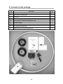
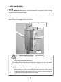
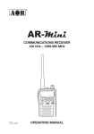
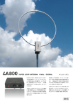
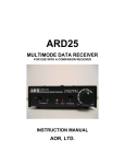
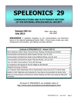
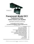
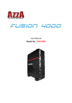
SUPER LOOP ANTENNA
LA800
Instruction manual
AOR Ltd.
Authority On Radio Communications
Table of contents
1. Introduction
.........................................
1
2. Included in this package . . . . . . . . . . . . . . . . . . . . . . . . . . . . . . . . .
2
3. Hardware setup
3
......................................
4. Operating instructions
.................................. 6
5. Directivity of a loop antenna
.............................
6. Characteristics of a “shielded” loop antenna
7. Options
7
................
8
.............................................
9
8. Specifications
........................................
10
1. Introduction
Thank you for purchasing the LA800 SUPER LOOP ANTENNA.
LA800 is AOR’s new and first OUTDOOR and WATERPROOF shielded loop antenna for
reception between 10kHz and 500MHz!
To get the best possible results from your LA800, we recommend that you read this manual
and familiarize yourself with the antenna.
First, a word of caution: LA800 is a RECEIVE ONLY antenna. Do not transmit with it or its
circuitry will be severely damaged, maybe even beyond repair.
In recent years, the increase in man-made local noise (typical city noise) poses a problem
for the reception of distant signals in the long wave, medium wave and shortwave bands.
LA800 is our latest product based on the technology we developed since the original LA320
indoor loop antenna. In addition to its exceptional directivity in order to minimize the effects
of local noise, the revolutionary LA800 offers, with its REMOTE TUNING SYSTEM, the
perfect solution to keep the antenna away from noise sources by setting it up in quiet areas!
While the control (tuning) box stays at hand’s reach, the WATERPROOF loop element can
be permanently setup outdoors.
10kHz to 500MHz, 6 position band switch to peak only on the wanted signal. Built-in low
noise amplifier for exceptional 20dB gain. Loop element diameter of 80cm for maximum
reception performance.
Remote tuning – The supplied 10m control and coaxial cables, separating the antenna
from the control box, allow to conveniently operate band switching and fine tuning controls
placed on the control box..
A relay system is used for band switching, providing excellent isolation characteristics.
The relay is efficiently placed inside the loop element, while you can operate it through the
control box via the control cable.
Electronic tuning from 150kHz〜 30MHz allows very sharp tuning to the desired
frequency. Shift the aligning point slightly to attenuate unwanted signals while amplifying
the wanted signal.
Waterproof – The loop element’s electronic circuitry is housed in a ABS plastic box, water
and dust proof to IP65 standard.
1
2. Included in this package
No.
Description
Qty
①
Loop element
1
②
Two U-bolts for mast mount
1
③
Control box
1
④
Control cable (LAN type) 10m
1
⑤
BNC (F)/BNC (F) RG-58U coaxial cable 10m
1
⑥
AC power supply
1
⑦
Printed instruction manual
1
⑧
(for Japanese market only)
1
⑨
Product sticker for the loop element box
1
4
8
7
9
5
6
3
2
1
2
3. Hardware setup
Caution!
LA800 is a RECEIVE ONLY antenna. Do not transmit with it or its circuitry will be severely
damaged, maybe even beyond repair.
As pictured below, mount the LA800 loop element to a (non-supplied) antenna mast, using
the supplied U-bolts.
Antenna masts are typically sold at home centers.
Antenna mast
(use 30 to 60mm diameter)
U-bolt
U-bolt
SAFETY PRECAUTIONS
If you are installing an antenna for the first time, for your own safety as well as
others, seek professional assistance.
Installation of this antenna near power lines is dangerous. Do not work on the
system or connect or disconnect cables during periods of lightning activity.
Do not work on a wet or windy day.
Do not locate the antenna near overhead power lines or other electric light or
power circuits, or where it can come into contact with such circuits. When
installing the antenna, take extreme care not to come into contact with such
circuits, as they may cause serious injury or death.
3
For balcony mount, you can also use typical satellite dish balcony mounts, as pictured below.
Such mounts are not supplied by AOR but are usually sold at home-centers.
The loop element’s electronic circuitry is housed in an ABS plastic box, water and dust proof
to IP65 standard.
◎ The control and coaxial cables enter the plastic box through two rubber gaskets as
shown below. Connect these to their respective sockets “ANT OUT” and “REMOTE”.
Coaxial cable
Control cable
4
◎ Run the coaxial and control cable a bit below and
then back up to the hole into the building, thus
providing a "drip loop" to prevent rain from running
down the cable and into the building
◎ On the receiver side, connect the control cable to the control box and the coaxial
cable directly to your receiver’s antenna socket. Finally, connect the AC power
supply to the control box.
LA
LA800 Loop
(outdoors)
Indoors
Control box
Receiver’s antenna
input socket
AC power supply
To connect LA800 to an antique receiver with 600Ω antenna terminal, use the optional
MC-600 Impedance Matching Transformer.
5
4. Operating instructions
◎ Connect the AC power supply and push the red power button on the control box. A blue
LED will light up.
◎ Tune your receiver to the desired frequency.
◎ Now you need to select one of the 6 available band ranges, using the band switch
numbered from 1 to 6. Refer to the printed switch number / band range information on
the top of the control box.
Please note that position 6 is non-tunable, as the loop is wired to act as an amplified
whip antenna.
Band switch
◎ Peak the received signal by turning the TUNING knob slowly to either the left or the right.
The white dot on the tuning know helps you to see the approximate location of the tuning.
For your reference, when the dot is on top as on the above illustration, the tuning PEAK
is approximately in the middle of the selected band.
For example for band switch position 1 (150kHz to 800kHz), it would be roughly peaked
on 475kHz.
Tuning is most critical above 3MHz. For best performance of LA800 and optimal
reception conditions, make sure the selected band is appropriate for the received
frequency, and search for the signal peak with the tuning knob.
◎ A loop antenna is very directional. Reception can be improved by using a third party
antenna mast rotator, and rotate the loop element until your receiver’s signal strength
meter (S-meter) deflects to maximum and the incoming signal sounds clearest. If your
receiver does not have an S-meter, simply adjust for maximum received signal.
6
5. Directivity of a loop antenna
A significant advantage of a loop antenna is its directional pattern, a “figure 8” shape with
two null points separated by 180 degrees. The null in reception that is located at right angles
to the plane of the loop can be used for interference reduction. On the other hand, received
signal strength is greatest in the directions indicated by the arrows.
Horizontal radiation pattern of LA800
NULL
NULL
NULL: Angle from which magnitude of the radiation pattern decreases to zero. In other
words, these are the sides from which the antenna receives the least.
Maximum reception performance is achieved when these sides of the loop face the
signal.
7
6. Characteristics of a “shielded” loop antenna
A shielded loop antenna is less susceptible to nearby electrical interference sources, thanks
to the electrostatic shielding of the loop afforded by the grounded metallic conduit enclosing
the wire coils.
By these principles, LA800 responds to the magnetic field rather than the electric field, thus
efficiently isolating the low frequency electrostatic noise from the distant signal to be
received.
Shield circuit of LA800
With this design, all parts of the loop will have the same capacitance to ground. The shield
also protects the loop from the induction field created by nearby disturbances. The induction
field refers to the electric and magnetic fields in the immediate vicinity of an antenna. Those
fields decrease rapidly in strength with distance, and the induction field is usually ignored.
However, wires and other metal objects near the loop can take energy from a passing wave
and produce induction fields that can induce spurious voltages in the loop.
A shield over a loop antenna will not appreciably decrease the amount of magnetic flux that
passes through the loop when a wave goes by - as long as it does not form a complete turn.
A gap is left in the shield so that it does not become a shorted turn. Without the gap, the
shield would reduce the magnetic field linking the loop so that no signal could be received by
the internal wire. With the gap, alternating currents can be induced in the metal shield and
voltages will be induced in the internal wire.
8
7. Options
GT-1 Galvanic isolation transformer
To be connected between the receiver and the LA800 antenna.
Does greatly reduce local noise by breaking the ground loop
effect between antenna and receiver.
Supported frequency range: 40kHz to 30MHz
MC-600 Impedance matching transformer
Passive impedance matching transformer interface which allows
your LA800 to be connected to any antique receiver with a 600Ω
antenna terminal. Supported frequency range: 10kHz to 30MHz.
MC-600 has the same isolation feature than the GT-1 accessory .
9
8. Specifications
LA800 Super Loop Antenna
Loop size
Diameter: 780mm (to the pipe center)
Loop type
Aluminum pipe: 20mm (2mm thick)
Frequency range
10kHz 〜 500MHz
Aligned range
150kHz 〜 30MHz (5 band selectable)
Unaligned range
Gain
Operating temperature
10kHz 〜 150kHz, 30MHz 〜 500MHz
20dB min.
-10℃ 〜 +60℃
Power requirements
12 〜 16V DC
Approx. 14mA〜100mA (band dependent) (figures with
supplied AC adapter)
Impedance
50 Ohm
Sizes (mm), projections
Loop element
800(W)x970(H)x84(D)
included
Control box
120(W)x38(H)x101(D)
Loop element
Approx. 1.4kg (Excluding mount U-bolts)
Weight
Control box
Approx. 240g
Supported mount mast
30〜60mm
AC power supply
Control cable (LAN type) 10m
Supplied accessories
BNC (F)/BNC (F) RG-58U coaxial cable 10m
Two U-bolts for mast mount
Printed user manual
• Product specifications and design subject to change without prior notice.
Power consumption
Assembled dimensions:
97cm
80 cm
12cm (in case of a 3.3cm diameter mount mast)
10
Memo:
®
AOR Ltd.
Authority On Radio Communications
2-6-4 Misuji, Taito-ku, 111-0055 Tokyo, Japan
www.aorja.com
(Sept.25, 2013)