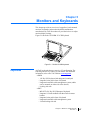
1
TAG Family of PRODUCTS
User Guide
Revision 1
January 24, 2006
P/N 1005172
22355 TAG Way, Dulles, VA 20166
Tel: (703) 406.3000 Fax: (703) 607.3853
Copyright © 2006 Technology Advancement Group (TAG)
All rights reserved. This publication and its contents are proprietary to TAG. No part of this publication may
be reproduced in any form or by any means without the written permission of TAG, 22355 TAG Way, Dulles,
Virginia 20166-9310.
TAG has made every effort to ensure the correctness and completeness of the material in this document. TAG
shall not be liable for errors contained herein. The information in this document is subject to change without
notice. TAG makes no warranty of any kind with regard to this material, including, but not limited to, the
implied warranties of merchantability and fitness for a particular purpose.
Trademarks
All trademarks, marks, names, or product names referenced in this publication are the property of their
respective owners, and TAG neither endorses nor otherwise sponsors any such products or services referred to
herein.
Important Safety Information
For your safety and protection, read this entire manual before you
attempt to use the server. In particular, read this safety section
carefully. Keep this safety information where you can refer to it if
necessary.
Types of Warnings Used
in this Manual
This section introduces the various types of warnings used in this
guide to alert you to possible safety hazards.
DANGER
Indicates an imminently hazardous situation, which, if not
avoided, will result in death or serious injury.
WARNING
Indicates a potentially hazardous situation, which, if not avoided,
could result in serious injury.
CAUTION
Indicates a potentially hazardous situation, which, if not avoided,
may result in minor or moderate injury.
CAUTION
Indicates a situation or practice that might result in property
damage.
Important Safety Information
Revision 1
i
ii
Important Safety Information
Revision 1
About This Manual
Scope and Audience
This manual provides information on the TAG family of servers
and is intended for use by system operators. TAG servers are
highly customizable; the specific components vary depending on
the mission requirements. The purpose of this document is to
provide you with an overview of the typical configuration found
in the TAG family of servers. Information is also provided on
how to identify your specific configuration. Procedural
information is included on how to remove and replace system
memory as well as hot-swappable components.
Organization
This manual is divided into the following chapters and appendix:
• Chapter 1 – TAG Server Overview provides a high-level
overview of the TAG 1U, 2U, and 4U servers.
• Chapter 2 – Server Components provides a detailed
information on the external and internal server components.
• Chapter 3 – Upgrading Memory and Replacing Hot-swap
Components provides procedures for replacing
hot-swappable components and replacing or adding system
memory.
• Chapter 4 – RAIDs provides a high-level overview that
defines RAID, the advantages and disadvantages of various
RAID levels, and guidelines to observe when implementing
RAID.
• Chapter 5 – Monitors and Keyboards provides an overview
of ruggedized, rack-mounted monitors, keyboards, and
monitor/keyboard combinations manufactured by TAG.
Procedures are provided on how to adjust monitor display
settings.
Revision Record
Revision
Date of Issue
Scope
1
January 24, 2006
Initial Release
About This Manual
Revision 1
iii
iv
About This Manual
Revision 1
About TAG
Summary of
Qualifications
Providing engineering services and solutions for our national
defense and homeland security is a responsibility that we don’t
take lightly. TAG is a recognized industry leader in developing
defense technologies and advanced electronics that support some
of the most complex solutions for battlespace information
networks and management systems in the world.
Our customers depend on our expertise to translate functional
requirements and performance objectives into specific design
criteria for individual elements and sub-systems that comprise
larger mission critical systems. For more than twenty years, we
have dedicated our experience in engineering to the design of
innovative tactical solutions for military and government, and to
providing a wide range of enterprise services and Information
Assurance in support of the Defense Information Systems
Agency’s (DISA) Net-Centric initiatives.
Core Competencies
TAG designs, manufactures, and supports advanced
communications electronics as well as integrates, operates, and
supports the users of defense communication and information
networks for several technology programs in the United States
and abroad. TAG has two operating segments consisting of the
Tactical Systems and Information and Engineering Services
business units;
Tactical Systems provides mechanical, electrical, and thermal
engineering for the design and development of MIL-STD
certified electronic data enabled systems that are built for
in-theater survivability and communication capability over joint
enterprise platforms such as DSN, GIG, STEP, GBS, and JTRS.
This includes the custom ruggedization of
commercial-off-the-shelf (COTS) and non-developmental items
(NDI). TAG’s mechanical engineering division designs and
fabricates custom hardened enclosures, using high performance
metal materials, to house and protect a variety of sensitive
devices and controls. TAG’s electrical engineering division
designs programmable power solutions and advanced sensor
technologies including digital receivers, advanced digital signal
processors and thermal detection systems. TAG’s thermal
About TAG
Revision 1
v
engineering applies survivability techniques to ensure systems
and instruments are designed to withstand harsh environmental
conditions encountered by land-based, airborne, and shipboard
system in operations.
Information and Engineering Services provides a wide range of
customer support operations, enterprise network and
communications engineering services combining the experience
and expertise required to achieve network and communication
interoperability for component hardware and software elements.
This includes design, simulation, analysis, and testing of the
components or systems for the support of command and control
operations. Our team of national security cleared network
engineering professionals provides planning support for
information systems, architectures, and networks while
developing strategies that lay the groundwork for sound technical
foundations for programmatic plans. Our expertise in analyzing,
designing, implementing, and managing network,
telecommunication and security solutions addresses the full
lifecycle approach to providing mission oriented enterprise class
services.
vi
About TAG
Revision 1
Contacting TAG
TAG provides online technical support on our Website at
www.tag.com. Here you will find:
•
•
•
•
•
Reference Guides
Drivers & Utilities
Technical Bulletins
Frequently Asked Questions (FAQs)
Shipping/Return Material Authorization (RMA) Policy
TAG’s Technical Support Call Center is manned 24-hours-a-day
by certified TAG Production Line Engineers. TAG’s global
presence extends to WORLDWIDE on-site system setup and
on-site technical support. For more information, contact TAG
Technical Coordinator’s at 1-877-TAG-TECH (824-8324).
Contacting TAG
Revision 1
vii
viii
Contacting TAG
Revision 1
Contents
Important Safety Information . . . . . . . . . . . . . . . . . . . . . i
Types of Warnings Used in this Manual . . . . . . . . . . . . . . . . . . . i
About This Manual . . . . . . . . . . . . . . . . . . . . . . . . . . . . . iii
Scope and Audience . . . . . . . . . . . . . . . . . . . . . . . . . . . . . . . . . . iii
Organization . . . . . . . . . . . . . . . . . . . . . . . . . . . . . . . . . . . . . . . . iii
Revision Record . . . . . . . . . . . . . . . . . . . . . . . . . . . . . . . . . . . . . iii
About TAG . . . . . . . . . . . . . . . . . . . . . . . . . . . . . . . . . . . . .v
Summary of Qualifications . . . . . . . . . . . . . . . . . . . . . . . . . . . . .v
Core Competencies. . . . . . . . . . . . . . . . . . . . . . . . . . . . . . . . . . . .v
Contacting TAG . . . . . . . . . . . . . . . . . . . . . . . . . . . . . . . vii
Chapter 1
TAG Server Overview . . . . . . . . . . . . . . . . . . . . . . . . . . . .1
Overview . . . . . . . . . . . . . . . . . . . . . . . . . . . . . . . . . . . . . . . . . . .1
Product Highlights . . . . . . . . . . . . . . . . . . . . . . . . . . . . . . . . . .1
1U Server . . . . . . . . . . . . . . . . . . . . . . . . . . . . . . . . . . . . . . . . . . .1
1U Server Front and Rear Panel Components . . . . . . . . . . . . .1
1U Server Internal Components . . . . . . . . . . . . . . . . . . . . . . . .3
2U Server . . . . . . . . . . . . . . . . . . . . . . . . . . . . . . . . . . . . . . . . . . .4
2U Server Front and Rear Panel Components . . . . . . . . . . . . .4
2U Server Internal Components . . . . . . . . . . . . . . . . . . . . . . . .5
4U Server . . . . . . . . . . . . . . . . . . . . . . . . . . . . . . . . . . . . . . . . . . .6
4U Server Front and Rear Panel Components . . . . . . . . . . . . .6
4U Server Internal Components . . . . . . . . . . . . . . . . . . . . . . . .8
Chapter 2
Server Components . . . . . . . . . . . . . . . . . . . . . . . . . . . . . .9
Identifying your Motherboard Model and Type. . . . . . . . . . . . . .9
Intel Motherboards . . . . . . . . . . . . . . . . . . . . . . . . . . . . . . . . .10
System Memory . . . . . . . . . . . . . . . . . . . . . . . . . . . . . . . . . . . . .11
Identifying System Memory. . . . . . . . . . . . . . . . . . . . . . . . . .11
TAG Approved BIOS. . . . . . . . . . . . . . . . . . . . . . . . . . . . . . . . .12
Common BIOS Settings . . . . . . . . . . . . . . . . . . . . . . . . . . . . .12
Printer Parallel Port-Uni., Bi-directional, Disable,
Enable, ECP, EPP. . . . . . . . . . . . . . . . . . . . . . . . . . . . . . . .12
COM/Serial Port . . . . . . . . . . . . . . . . . . . . . . . . . . . . . . . . .12
Floppy Drives . . . . . . . . . . . . . . . . . . . . . . . . . . . . . . . . . . .12
Hard Drives. . . . . . . . . . . . . . . . . . . . . . . . . . . . . . . . . . . . .13
Contents
Revision 1
ix
Boot Sector Virus . . . . . . . . . . . . . . . . . . . . . . . . . . . . . . . .13
Memory . . . . . . . . . . . . . . . . . . . . . . . . . . . . . . . . . . . . . . .13
Boot Sequence . . . . . . . . . . . . . . . . . . . . . . . . . . . . . . . . . .13
Date and Time . . . . . . . . . . . . . . . . . . . . . . . . . . . . . . . . . .13
Passwords . . . . . . . . . . . . . . . . . . . . . . . . . . . . . . . . . . . . . .14
Plug and Play BIOS . . . . . . . . . . . . . . . . . . . . . . . . . . . . . .14
Power Management . . . . . . . . . . . . . . . . . . . . . . . . . . . . . .14
Identifying your I/O Connectors . . . . . . . . . . . . . . . . . . . . . . . .14
Standard Server Components . . . . . . . . . . . . . . . . . . . . . . . . . . .15
Floppy Drives . . . . . . . . . . . . . . . . . . . . . . . . . . . . . . . . . . . . .15
Tape Drive . . . . . . . . . . . . . . . . . . . . . . . . . . . . . . . . . . . . . . .17
Optical Drives. . . . . . . . . . . . . . . . . . . . . . . . . . . . . . . . . . . . .17
Power Supply . . . . . . . . . . . . . . . . . . . . . . . . . . . . . . . . . . . . .18
Standard Non-hot-swap Power Supply. . . . . . . . . . . . . . . .18
Hot-swap Power Supply . . . . . . . . . . . . . . . . . . . . . . . . . . .19
Identifying the Power Supply Manufacturer
and Model . . . . . . . . . . . . . . . . . . . . . . . . . . . . . . . . . . . .19
Silencing the Audible Alarm . . . . . . . . . . . . . . . . . . . . .20
Additional Optional Components. . . . . . . . . . . . . . . . . . . . . . . .21
Serial Interface Cards . . . . . . . . . . . . . . . . . . . . . . . . . . . . . . .21
PC-based Card Readers . . . . . . . . . . . . . . . . . . . . . . . . . . . . .21
Time Sync Cards . . . . . . . . . . . . . . . . . . . . . . . . . . . . . . . . . .21
DDC Dual Channel MIL-STD 1553 Cards . . . . . . . . . . . . . .22
Video Capture Cards . . . . . . . . . . . . . . . . . . . . . . . . . . . . . . .22
Identifying Server Components using Device Manager . . . . . .22
Working with Device Properties . . . . . . . . . . . . . . . . . . . . . .24
Installing and Removing Hardware in Windows . . . . . . . . . . . .26
Using the Add New Hardware Wizard. . . . . . . . . . . . . . . . . .26
Installing Legacy Peripherals . . . . . . . . . . . . . . . . . . . . . . . . .27
Removing Legacy Peripherals . . . . . . . . . . . . . . . . . . . . . . . .27
Chapter 3
Upgrading Memory and Replacing Hot-swap
Components . . . . . . . . . . . . . . . . . . . . . . . . . . . . . . . . . . .31
Preventing Static Electricity . . . . . . . . . . . . . . . . . . . . . . . . . . . .31
Replacing a Hot-swap Power Supply Module . . . . . . . . . . . . . .32
Replacing a Hot-swap Hard Drive . . . . . . . . . . . . . . . . . . . . . . .33
Removing the Server Cover . . . . . . . . . . . . . . . . . . . . . . . . . . . .34
Adding or Replacing System Memory . . . . . . . . . . . . . . . . . . . .34
Chapter 4
RAIDs . . . . . . . . . . . . . . . . . . . . . . . . . . . . . . . . . . . . . . . .37
RAID Defined . . . . . . . . . . . . . . . . . . . . . . . . . . . . . . . . . . . . . .37
Reasons for RAID . . . . . . . . . . . . . . . . . . . . . . . . . . . . . . . . . . .37
x
Contents
Revision 1
RAID Level 0 . . . . . . . . . . . . . . . . . . . . . . . . . . . . . . . . . . . . . . .38
RAID Level 1 . . . . . . . . . . . . . . . . . . . . . . . . . . . . . . . . . . . . . . .38
RAID Level 5 . . . . . . . . . . . . . . . . . . . . . . . . . . . . . . . . . . . . . . .38
RAID 50 . . . . . . . . . . . . . . . . . . . . . . . . . . . . . . . . . . . . . . . . . . .39
About RAID Global and Hot Spares . . . . . . . . . . . . . . . . . . . . .40
Global and Dedicated Hot Spares. . . . . . . . . . . . . . . . . . . . . .40
Chapter 5
Monitors and Keyboards. . . . . . . . . . . . . . . . . . . . . . . . .41
. . . . . . . . . . . . . . . . . . . . . . . . . . . . . . . . . . . . . . . . . . . . . . . .41
Keyboards. . . . . . . . . . . . . . . . . . . . . . . . . . . . . . . . . . . . . . . . . .41
LCD Monitors . . . . . . . . . . . . . . . . . . . . . . . . . . . . . . . . . . . . . .42
LCD / Keyboards . . . . . . . . . . . . . . . . . . . . . . . . . . . . . . . . . . . .42
Power Requirements. . . . . . . . . . . . . . . . . . . . . . . . . . . . . . . . . .45
Display Adjustments . . . . . . . . . . . . . . . . . . . . . . . . . . . . . . . . .45
Servicing. . . . . . . . . . . . . . . . . . . . . . . . . . . . . . . . . . . . . . . . . . .50
Troubleshooting . . . . . . . . . . . . . . . . . . . . . . . . . . . . . . . . . . . . .50
No Image . . . . . . . . . . . . . . . . . . . . . . . . . . . . . . . . . . . . . . . .50
Image Position . . . . . . . . . . . . . . . . . . . . . . . . . . . . . . . . . . . .50
Image appearance . . . . . . . . . . . . . . . . . . . . . . . . . . . . . . . . . .50
Backlight. . . . . . . . . . . . . . . . . . . . . . . . . . . . . . . . . . . . . . . . .50
Continued Failure . . . . . . . . . . . . . . . . . . . . . . . . . . . . . . . . . .51
Contents
Revision 1
xi
xii
Contents
Revision 1
Chapter 1
TAG Server Overview
This chapter provides an introductory overview of the TAG
family of tactical servers. TAG servers are highly customizable;
the specific components vary depending on the mission
requirements. Your system may contain components not
described in this chapter. For detailed information on these
components, refer to the manufactures website or contact TAG
Technical Support at [email protected]. For more
information, see Contacting TAG on page vii.
Overview
TAG’s tactical servers combine Intel® Xeon® technology with
state-of-the-art mechanical, thermal and electrical engineering to
create customized systems that perform above and beyond end
user or program specifications. Our tactical servers are designed
to meet and exceed many MIL-STD requirements to ensure
survivability in the field.
Product Highlights The following list provides an overview of features incorporated
into all TAG servers.
• Available with single or dual Intel Xeon processors
• Designed to meet MIL-STD-901D, MIL-STD-810F,
MIL-STD-167, MIL-STD-461E, and MIL-STD-740
• Contains an intelligent fan controller (acoustically optimized,
environmentally aware)
• Small-form factor chassis made of environmentally protected
5052 aluminum-alloy strain hardened and stabilized chassis
• Proven to function at an operating temperature of 0°-50°C
1U Server
The 1U server utilizes a small form-factor, 17-inch deep
(short-rack) chassis.
1U Server Front and Rear Refer to Figure 1-1 and Table 1-1 for the typical 1U server front
Panel Components and rear panel components and connectors.
Chapter 1 TAG Server Overview
Revision 1
1
)URQW
5HDU
Figure 1-1: 1U Server Components and Connectors
Table 1-1: 1U Server Components and Connectors
No.
Description
1
CD/DVD ROM
2
Hard disk drive LED indicator
3
Hot-swap hard drive (2 places)
4
Reset switch
5
Power switch
6
Power LED
7
Floppy drive
8
Keyboard/mouse connector
9
USB connectors
10
Optional AGP/PCI card slot
11
AC power connector
12
Ground stud
13
SCSI connector *
14
Serial port connector
15
Video connector
16
NIC connector
17
Serial port connector
* Availability of this SCSI connector depends on the motherboard installed.
2
Chapter 1 TAG Server Overview
Revision 1
1U Server Internal Refer to Figure 1-2 and Table 1-2 for a typical configuration of
Components the 1U server internal components.
2
3
1
4
5
6
7
Figure 1-2: 1U Server Internal Components
Table 1-2: 1U Server Components and Connectors
No.
Description
1
CD/DVD ROM
2
Power supply
3
PCI card
4
Memory banks
5
Motherboard
6
Fan assembly
7
Hot-swap hard drive (2 places)
Chapter 1 TAG Server Overview
Revision 1
3
2U Server
The 2U server utilizes a small form-factor, 24-inch deep chassis
with the storage capacity of up to 1.2TB (using SCSI hard
drives).
2U Server Front and Rear Refer to Figure 1-3 and Table 1-3 for the typical 2U server front
Panel Components and rear panel components and connectors.
)URQW
5HDU
Figure 1-3: 2U Server Components and Connectors
Table 1-3: 2U Server Components and Connectors
No.
4
Chapter 1 TAG Server Overview
Revision 1
Description
1
USB connectors
2
Hot-swap power alarm
3
Power switch
4
Hard drive LED
5
Reset switch
6
Hot-swap hard disk drive (4 places)
7
Ground stud
8
Serial port connector
9
Slots for optional cards (3 PCI or 1 AGP)
10
Retention bracket
Table 1-3: 2U Server Components and Connectors (Continued)
No.
Description
11
Dual hot-swap power supply
12
Onboard SCSI connector (optional)
13
USB connectors
14
Video connector
15
Network Interface Card (NIC) connectors
16
Serial connector
17
Keyboard/mouse connector
2U Server Internal Refer to Figure 1-4 and Table 1-4 for a typical configuration of
Components the 2U server internal components.
2
3
4
1
5
6
7
8
Figure 1-4: 2U Server Internal Components
Chapter 1 TAG Server Overview
Revision 1
5
Table 1-4: 2U Server Internal Components
No.
4U Server
Description
1
Hot-swap hard drive (4 places)
2
Power supply
3
PCI riser bracket
4
Memory banks
5
Motherboard
6
Heat sink air duct system
7
Fan assemblies (6 places)
8
Fan controller board
The 4U server utilizes a small form-factor, 16.5-inch deep chassis
with specialized front-accessible fans that provide proper air flow
and extreme cooling of the CPU.
4U Server Front and Rear Refer to Figure 1-5, Figure 1-6, and Table 1-5 for the typical 4U
Panel Components server front and rear panel components and connectors.
2
1
3
4
Front
6
5
Figure 1-5: 4U Server Components and Connectors (Front View)
6
Chapter 1 TAG Server Overview
Revision 1
7
8
8
Rear
15
14
13
12
9
11
10
Figure 1-6: 4U Server Components and Connectors (Rear View)
Table 1-5: 4U Server Components and Connectors
No.
Description
1
CD/DVD ROM
2
Power alarm
3
Hard disk LED
4
Hot-swap hard drives (6 places)
5
Hot-swap fan module
6
Power switch
7
Serial port connector
8
Hot-swap fans (3 places)
9
Power supply
10
Optional PCI cards (6 places)
11
NIC connectors
12
Optional SCSI connector
13
Video connectors (2 places)
14
Keyboard / Mouse connectors
15
USB connectors
Chapter 1 TAG Server Overview
Revision 1
7
4U Server Internal Refer to Figure 1-7 and Table 1-6 for a typical configuration of
Components the 4U server internal components.
2
1
3
2
4
5
Figure 1-7: 4U Server Internal Components
Table 1-6: 4U Server Components and Connectors
No.
8
Chapter 1 TAG Server Overview
Revision 1
Description
1
Power filter boards
2
How-swap fans (3 places)
3
PCI cards (slots for 6 cards)
4
Motherboard
5
Hot-swap hard drives (6 places)
Chapter 2
Server Components
This chapter provides an overview of the most common
components installed in TAG tactical servers. Information is also
provided on how to identify specific components within your
server. For detailed information on the specific components
installed in your server, refer the manufactures website.
Identifying your
Motherboard Model and
Type
The version of an Intel server motherboard can be determined by
decoding the last three digits of the board part number.
For example: C44686-703 The number following the “-” is as
follows:
7 = Fabrication (FAB) Number
03 = Revision 3.
The board part number can be found on the motherboard. The
board part number can also be determined by using Intel Server
Management software.
Chapter 2 Server Components
Revision 1
9
Intel Motherboards Figure 2-1 shows the primary components of the Intel
SE7520JR2 motherboard. Table 2-1 lists these components. For
detailed information on this and other Intel motherboards, refer to
the Intel website at: www.intel.com.
$7,
,QWHO
(
(
,QWHO
,QWHO
;HRQ
,QWHO
;HRQ
(
,QWHO
Figure 2-1: Intel SE7520JR2 Server Board
10
Chapter 2 Server Components
Revision 1
Table 2-1: SE7520JR2 Server Board Components
No.
System Memory
Description
1
Support for two Intel Xeon processors with 800MHz system bus
2
Support for up to six DIMMs of Registered ECC DDR 266/333 or
DDR2 400 SDRAM
• Support for memory sparing and mirroring
3
Rear panel connectors. This includes:
• Two Gigabit Ethernet connectors
• PS/2 keyboard and mouse connectors
• Three USB connectors
• Video connector
• Serial connector
4
Four independent PCI buses supporting PCI Express, PCI-X, and
PCI, accessed through two riser slots:
• Two adapter slots on a 1U system
• Up to six adapter slots on a 2U system
5
Integrated graphics
• ATI RAGE* XL SVGA PCI video controller with 8 MB of video
memory
6
Optional integrated single- or dual-channel Ultra320 SCSI with
support for RAID 0 and 1
7
Intel E7520 chipset
8
One IDE connector supporting two ATA 100 IDE channels
9
Intel Management Module upgrade connector
• Support for Intel Management Module Professional Edition and
Intel Management Module Advanced Edition (optional
upgrades)
10
Intel Server Management 8
• Onboard Platform Instrumentation
The type and amount of system memory, or RAM (random access
memory), on your server depends on the motherboard installed
and how it was configured. For example, the motherboard shown
in Figure 2-1 on page 10 has six DIMMs (dual in-line memory
modules), two per channel, and is capable of support up to 12 GB
of system memory.
Identifying System Memory Refer to Identifying your Motherboard Model and Type on
page 9. Once you have identified the motherboard, TAG technical
support can assist you in determining the type and amount of
system memory in your system. See Contacting TAG on page vii
for information on how to contact Technical Support.
For information on replacing or upgrading your system memory,
refer to Adding or Replacing System Memory on page 34.
Chapter 2 Server Components
Revision 1
11
TAG Approved BIOS
The BIOS (basic input/output system) is the program stored on
the CMOS that the server’s microprocessor uses to get the system
started after you turn it on. The BIOS also manages data flow
between the computer’s operating system and attached devices
such as the hard disk, video adapter, keyboard, and mouse.
CAUTION
The BIOS installed on your server was loaded and tested with all
the devices initially installed in your system. If you desire to have
the BIOS updated, consult TAG technical support in advance as
updates to your approved BIOS may cause your system to become
unstable or inoperable.
Common BIOS Settings The following sections discuss the various CMOS settings.
Printer Parallel Port-Uni., Settings in the CMOS enable you to configure a parallel port to
Bi-directional, Disable, Enable, use Enhanced Parallel Port (EPP) or Enhanced Parallel Port
ECP, EPP (ECP). ECP. EPP and ECP are bi-directional standards, operate in
8-bit, and allow data transfer speed of approximately 2 MB/s.
Some of the main differences are that ECP supports Direct
Memory Access (DMA) and data compression, which enables
higher transfer rates.
It is also possible to completely disable the parallel port in the
BIOS. Most BIOS’ allow you to set the DMA channel, when the
port mode is set to ECP.
COM/Serial Port Most personal computers have two serial ports. In the BIOS you
can assign COM1/COM2/COM3/COM4 to serial port 1 or 2.
Most BIOS’ also allow you to set the I/O and IRQ but this is
mostly done automatically.
Floppy Drives The floppy drive(s) can be enabled or disabled in the BIOS. The
BIOS also allows you to choose the capacity of the media.
• 360 KB 5.25-inch
• 1.2 MB 5.25-inch
• 720 KB 3.5-inch
• 1.44 MB 3.5-inch
• 2.88 MB 3.5-inch
Some BIOS’ allow you to swap A: and B: and disable seeking a
floppy disk for a boot sector during startup.
12
Chapter 2 Server Components
Revision 1
Hard Drives Most modern BIOS’ allow automatic detection of disk
parameters. The settings can be individually configured for the
primary master and slave device and the secondary master and
slave device. The following are some of the primary settings that
apply to hard drives as well as CD/DVD-ROM drives, tape
backup drive, etc.
• Type
Common disk types are:
– User-defined Cylinders, Heads, Sectors (CHS) values
– Auto-automatically detects hard disks parameters at every
startup
– 1-46-predefined combinations of CHS values
– CDROM-used for AT Attachment Packet Interface
(ATAPI) CD-ROM drives
– ARMD-used for ATAPI ZIP and LS 120 drives
– DVDROM
• Size—Determines the capacity of the drive
• CHS values:
– Number of Cylinders
– Number of Heads
– Number of Sectors
• LBA (Large Block Addressing)-technology to overcome the
528 MB limit.
Boot Sector Virus A common setting related to hard drives. When enabled, the
BIOS issues a warning message/beep if an attempt is made to
write to the boot sector or partition table of a hard disk.
Memory Parity adds an extra bit (odd or even) to the 8-bit data-string to
ensure data integrity in memory modules. Its successor, ECC,
provides improved data integrity by adding information about
individual bits.
Boot Sequence This setting is used to control the order that the BIOS uses during
the boot process to look for a boot device from which to load the
operating system. For example:
1. CD
2. Floppy
3. Hard Disk
Date and Time The Date and Time is set in the BIOS, stored in CMOS, and
maintained by CMOS battery.
Chapter 2 Server Components
Revision 1
13
Passwords In most cases a user (startup) password and a supervisor (setup)
password can be set in the CMOS. When a Setup password is
required, the computer will prompt for it when you try to access
the BIOS setup. When a Startup password is configured, the
computer will prompt for it at every startup.
The CMOS password can be reset by shortening the “CMOS
restore to factory defaults jumper” or by temporarily removing
the CMOS battery.
Plug and Play BIOS Today’s BIOS’ are Plug and Play (PnP)-aware. This means they
are able to automatically assign resources such as IRQ and DMA
to PnP devices.
Information about PnP devices is stored in a separate area of
non-volatile CMOS memory, called the Extended System
Configuration Database (ESCD). Both the PnP BIOS and the
operating system can access this area and communicate with each
other about resource settings assigned to PnP devices as well as
non-PnP devices. For example, when a fixed interrupt request
(IRQ) is manually assigned to a particular device using Device
Manager, Windows will write this information to the ESCD on
shutdown thereby preventing the BIOS from assigning the same
IRQ to a PnP device at startup.
You can also reserve IRQs for non-PnP devices in the CMOS
setup, this will prevent the BIOS from assigning these reserved
resources to PnP devices, a common example is a legacy sound
card that needs IRQ 5.
Power Management Modern motherboards provide Advanced Configuration and
Power Management Interface (ACPI) settings such as wake-up,
power button function and standby/suspend timers. These
functions are configured in the CMOS Setup.
Identifying your I/O
Connectors
14
Chapter 2 Server Components
Revision 1
Figure 2-2 shows a typical configuration of I/O connectors. Your
configuration may vary depending on the motherboard installed
in your server; however, the color coding should remain
consistent. I/O connectors are color-coded in compliance with PC
99 recommendations. Table 2-2 lists the colors used.
Figure 2-2: I/O Connectors Typical Configuration
Table 2-2: I/O Connector Color Codes
Item
Standard Server
Components
Description
Color
1
PS/2 keyboard port
Purple
2
PS/2 mouse port
Green
3
Parallel port
Burgundy
4
Ethernet
Black
5
Audio line in (optional)
Light blue
6
Audio line out (optional)
Lime green
7
Microphone in (optional)
Pink
8
USB
Black
9
Serial port A
Teal
10
Serial port B
Teal
11
USB ports
Black
The following sections provide information on the standard
system components installed on TAG servers.
Floppy Drives The floppy disk drive is a removable storage component and part
of the storage subsystem. Currently TAG uses three styles of
floppy disk drives. The drive style installed in your system
depends upon the system configuration and motherboard.
Chapter 2 Server Components
Revision 1
15
The most common is the low-profile (or micro), internally
mounted 1.44MB floppy drive as shown in Figure 2-3.
Figure 2-3: Low-profile 1.44MB Floppy Disk Drive
Another popular configuration is the standard size or half-height
floppy disk drive as shown in Figure 2-4.
Figure 2-4: Standard 1.44MB Floppy Disk Drive
Some of our Tactical Hybrid Servers use the external Universal
Serial Bus (USB) floppy disk drive as shown in Figure 2-5. The
USB interface takes advantage of today’s operating systems
16
Chapter 2 Server Components
Revision 1
ability to detect dynamically installed devices and to avoid device
interrupt conflicts with other applications and devices.
Figure 2-5: USB 1.44MB Floppy Disk Drive
Tape Drive The tape drive (Figure 2-6) is a removable storage component
and part of the storage subsystem. Tape backup provides the
ability to periodically copy the contents of all or a designated
amount of data from its usual storage device to a tape cartridge
device. Tape backup can be done manually or with appropriate
software, can be programmed to run automatically.
Figure 2-6: Tape Drive
Optical Drives The type of optical drive installed in your server varies per
configuration. Figure 2-7 show an example of a CD-ROM drive.
TAG server typically come with CD-ROM (Compact Disk-Read
Only Memory). CD-ROM drives are generally used to install
Chapter 2 Server Components
Revision 1
17
software. CD-RW (Compact Disk-Re-writable) drives can be
used to store and backup data.
C
O
M
P
A
C
T
Figure 2-7: Optical Drive
Power Supply TAG offers many power supplies; each TAG server is matched
with a power supply to provide the correct load to all devices
while keeping heat within the system to a minimum.
Note: Functional system operation as well as component life can
be seriously degraded by excessive heat within your system.
WARNING
Power supplies contain dangerous voltages. Before attempting to
work on any power supply always unplug the device and drain the
power source by turning the server on after the power supply has
been disconnected. Failure to follow these instructions could result
in serious injury due to electrical shock.
Standard Non-hot-swap Power The typical TAG non-hot-swap power supply is a load-balancing,
Supply auto-switching power supply. Figure 2-8 shows a standard 1U
power supply. As with all TAG power supplies, it is designed to
provide the correct load to all devices, while not supplying
excessive heat within the system.
The power supply is secured in place with specially designed
brackets and secured with chemically coated screws to protect
your system from damage due to shock and vibration.
18
Chapter 2 Server Components
Revision 1
Field service of these power supplies is not recommended.
Contact TAG Technical Support at [email protected] to
arrange to have the power supply serviced in your server.
Detailed troubleshooting procedures, and frequently asked
questions (FAQs) can also be found on the TAG Website
(www.tag.com). For more information, see Contacting TAG on
page vii.
Figure 2-8: Standard 1U Power Supply
Hot-swap Power Supply To satisfy reliability requirements, TAG servers are designed with
hot-swappable power supplies. If in the event of a power supply
module failure or if the power source fails and only one module is
receiving power, an audible alarm sounds. For procedures on how
to hot-swap a power supply module refer to Replacing a
Hot-swap Power Supply Module on page 32.
Identifying the Power Supply Manufacturer and Model
Although most TAG power supplies for the 1U and 4U series
servers are similar in physical sizes, and physical characteristics,
some servers use smaller foot print power supplies. Figure 2-9
shows a typical 4U hot-swap power supply.
Chapter 2 Server Components
Revision 1
19
Figure 2-9: 4U Hot-swap Power Supply
If your server has two power input receptacles, then the server is
equipped with a redundant hot-swap power supply.
Silencing the Audible Alarm
To silence the audible alarm and determine its cause, do the
following:
• Press the Silence Alarm symbol (Figure 2-10) on the server
front panel.
Figure 2-10: Silence Alarm Symbol
To determine the cause of the alarm:
– Verify that the power cable is plugged into the power
source.
– Verify that the power supply module has not be removed or
unplugged.
Detailed troubleshooting procedures, and frequently asked
questions (FAQs) can also be found on the TAG Website
(www.tag.com). For more information, see Contacting TAG on
page vii.
20
Chapter 2 Server Components
Revision 1
Additional Optional
Components
The following sections provides on overview of the optional
components that may be included with your server. For detailed
information on these components, refer to the manufactures
website or contact TAG Technical Support at
[email protected]. For more information, see Contacting
TAG on page vii.
Serial Interface Cards The 7201 Peripheral Component Interconnect (PCI) serial
interface provides two serial ports, each individually configurable
for RS-232, RS-422, or RS-485. The board is capable of data
rates to 460.8K bps and automatically handles RS-485 transmitter
enable/disable. The 7201 utilizes 16C550 Universal
Asynchronous Receiver-Transmitters (UARTs) that provide
16-byte Tx/Rx first-in, first-outs (FIFO). Ordering options allow
the choice of UARTs with larger FIFOs, support for custom baud
rates, and 9-bit protocols.
PC-based Card Readers PC card readers extend a computer system’s capabilities by
providing universal access to the LYNKS Hardware Secure
Modules (HSM) and Fortezza Crypto Card.
Functions:
• Secure Messaging: e-mail, workflow, and EDI
• Electronic Wallets: Digital cash and electronic checks
• Strong Authentication: Positively verify user's identity
• Electronic Commerce: Conducted over the Internet using
Visa®/MasterCard® SET™
• Fraud Detection: Detect changes to paper and electronic
documents
• Electronic Notary: Digitally sign and time stamp legal
documents
• Secure Storage: Secure on-card storage is tamper proof
• Secure Content Delivery: CD-ROM, set-top boxes
Time Sync Cards The TPRO-PCI performs timing and synchronization functions
referenced to an input time code signal. The board synchronizes
its on-board clock to the incoming time code. The on-board
clock's time is also provided as an IRIG-B output. Other features
include a time-tag TTL input, a programmable “heartbeat” pulse
or squarewave output (with interrupt capability), and a
programmable “match” start/stop time output (with interrupt
capability).
Chapter 2 Server Components
Revision 1
21
DDC Dual Channel MIL-STD The BU-65569iX is a single-channel or multi-channel
1553 Cards MIL-STD-1553 PCI card. The BU-65569iX includes one to four
dual redundant 1553 channels. The design of the BU-65569iX
leverages the Enhanced Mini-ACE. Each channel may be
independently programmed for BC/RT/Monitor, or RT/Monitor
mode.
Video Capture Cards The Osprey-100 captures full frame video at 30 frames per
second and allows for Windows Media encoding along with
capture into other popular software packages.
Identifying Server
Components using
Device Manager
The Device Manager is one of Windows' most useful diagnostic
tools. It lets you see all of the devices attached to your computer,
and which resources they are each using. To access the Device
Manager do the following:
1. Click Start, point to Settings, and then click Control Panel.
Result: The Control Panel appears (Figure 2-11).
Figure 2-11: Control Panel
22
Chapter 2 Server Components
Revision 1
2. Double-click the System icon.
Result: The System Properties dialog box appears
(Figure 2-12).
Figure 2-12: System Properties Dialog Box
3. Click the Hardware tab, and then click the Device Manager
button.
Result: The Device Manager appears displaying a list of your
hardware devices organized by type (Figure 2-13).
Figure 2-13: Device Manager Dialog Box
Chapter 2 Server Components
Revision 1
23
After opening Device Manager, you will see a list of all the
devices Windows detected on your system. The Device Manager
display is recreated each time the computer is started, or
whenever a dynamic change to the computer configuration
occurs, such as addition of a new device while the system is
running.
Note: To include hidden devices, on the View menu, click Show
hidden devices. A check mark next to Show hidden devices
indicates hidden devices are showing. Click it again to clear the
check mark. Hidden devices include non-PnP devices and devices
that have been physically removed from the computer but have not
had their drivers uninstalled
The devices shown represent the computer's current hardware
configuration information. Any non-functioning devices are
displayed with an exclamation point, indicating that a problem
exists with the device; disabled devices are displayed with a small
red “x” over the icon.
You can use Device Manager to enable or disable devices,
troubleshoot devices, update drivers, use driver rollback, and
change resources such as interrupt requests (IRQs) assigned to
devices.
Working with Device To display a device’s properties do the following:
Properties 1. Access the Device Manager as describe in steps 1 through 3
of Identifying Server Components using Device Manager on
page 22.
Result: The Device Manager appears displaying a list of your
hardware devices organized by type (Figure 2-14).
Figure 2-14: Device Manager Dialog Box
24
Chapter 2 Server Components
Revision 1
2. In the Device manager dialog box (Figure 2-13), double-click
the device, or select the device and then click the Properties
toolbar button.
Result: The Properties dialog box for the selected device
appears (Figure 2-15)..
Figure 2-15: Properties Dialog Box
In the device’s Properties dialog box, there might be several tabs.
You can view the status and configuration information, as well as
the device manufacturer, device type, and location in the upper
portion of the General tab.
The Device status box in the middle of the General tab displays
the status of the device, including any errors. If the device has any
problems, the Device Status box briefly describes the problem,
and usually describes the appropriate course of action to correct
the problem. Click Troubleshoot... to use the built-in
mechanisms for detecting the nature of the problem.
Other tabs include the Driver tab, which displays the details of
the driver being used. This tab also lets you update or uninstall
the driver. The Resources tab displays the hardware resources
being used. This tab allows you to see and resolve any conflicts
caused by non-PnP devices. Along with these tabs, some devices
have additional advanced settings or tabs for device-specific
settings.
Chapter 2 Server Components
Revision 1
25
Installing and Removing
Hardware in Windows
Plug and Play (PnP) is a standard that makes installing new
hardware devices easier. Prior to PnP, installing new hardware
meant finding and installing peripheral drivers and making sure
the new device didn't conflict with another device. Theoretically,
if you have a computer designed for PnP and are using a PnP
operating system (like Windows), installing a printer, sound card,
modem, or other peripheral is a simple matter of plugging in the
device.
It’s not always quite this simple. Assuming you are using a PnP
computer, when you attach a PnP device, you may see a message
indicating that Windows has recognized the new device-either
immediately or the next time you start up your system. If
Windows needs a driver that is not currently installed, you may at
that point be asked to insert a disk or the Windows CD-ROM. If
you don't see a message but the device appears to be working,
you can assume that everything is fine.
Using the Add New If the device is not working properly, try using the Add New
Hardware Wizard Hardware Wizard. To run this wizard do the following:
1. From the Start menu, point to Settings and then click
Control Panel.
Result: The Control Panel dialog box appears (Figure 2-16).
Figure 2-16: Control Panel
26
Chapter 2 Server Components
Revision 1
2. Double-click the Add Hardware icon.
Result: The Add Hardware Wizard dialog box appears
(Figure 2-17).
Figure 2-17: Add Hardware Wizard
3. Follow the on-screen instructions.
Installing Legacy When you install what Microsoft calls a legacy peripheral, you
Peripherals will need to use the Add Hardware Wizard, as described Using
the Add New Hardware Wizard on page 26, to let Windows know
about the new device.
The term legacy refers to anything that’s no longer
on the cutting edge.
Note:
Removing Legacy When removing a legacy peripheral from your system, you need
Peripherals to let Windows know that the device is gone. This enables
Windows to reuse the resources (places in memory and internal
communications channels) that it previously allocated to that
device.
To tell Windows that you have removed a legacy device, perform
the following steps:
1. From the Start menu, point to Settings and then click
Control Panel.
Chapter 2 Server Components
Revision 1
27
Result: The Control Panel appears (Figure 2-18).
Figure 2-18: Control Panel
2. Double-click the System icon.
Result: The System Properties dialog box appears
(Figure 2-19).
Figure 2-19: System Properties Dialog Box
28
Chapter 2 Server Components
Revision 1
3. Click the Hardware tab.
4. Click the Device Manager button.
Result: The Device Manager appears displaying a list of your
hardware devices organized by type (Figure 2-20).
Figure 2-20: Device Manager Dialog Box
5. Click the name of the item you have removed from your
system.
If you don't see the item, look for a category heading that
describes the type of device you removed, and then click the
plus sign to its left to display a list of items in that category.
6. From the Action menu, click Uninstall.
Result: The system asks you to confirm the removal.
7. Click OK.
Chapter 2 Server Components
Revision 1
29
30
Chapter 2 Server Components
Revision 1
Chapter 3
Upgrading Memory and Replacing
Hot-swap Components
This chapter provides procedures for replacing hot-swappable
components as well as procedures for replacing or adding system
memory.
Preventing Static
Electricity
The components inside your computer are extremely sensitive to
static electricity, also known as electrostatic discharge (ESD).
ESD can permanently damage electrostatic discharge-sensitive
components in your server.
To prevent ESD damage, follow these guidelines before opening
the server case:
• Turn off the server and unplug the power cord before opening
the case.
• Wear a grounding wrist strap and attach it to a bare metal part
of the server, workbench, or other grounded connection
(Figure 3-1).
$WWDFKHQGWRJURXQGHGFRQQHFWLRQ
Figure 3-1: Attaching a Static Wrist Strap
• Do not insert any object into the vent holes on the case or the
power supply.
• Touch a bare metal surface on the back of the computer, a
bare metal surface on your workbench, or other grounded
object before handing DIMMs or other components.
Chapter 3 Upgrading Memory and Replacing Hot-swap Components
Revision 1
31
Before working with computer components, follow these
guidelines:
• Avoid static-causing surfaces such as carpeted floors, plastic,
and packing foam.
• Remove components from their antistatic bags only when
you are ready to use them. Do not lay components on the
outside of antistatic bags because only the inside of the bags
provide electrostatic protection.
• Always hold memory modules and components by their
edges or their metal mounting brackets. Avoid touching the
edge connectors and components on the cards. Never slide
memory modules or components over any surface.
Replacing a Hot-swap
Power Supply Module
Your TAG server was designed with the ability to hot-swap a
power supply module without disconnecting system power. Refer
to Figure 3-2 and the steps that follow to hot-swap a power
supply module.
Note: If you need to remove both modules, you must shutdown
the system, unplug the power source from the unit and drain the
systems onboard battery by pressing the on/off switch and holding
it in place for approximately 10 seconds to drain any charge that
might be retained by the systems motherboard.
1. Obtain certified replacement module from TAG. For more
information, see Contacting TAG on page vii.
2. Depending on the series of your server, either a retention
bracket or filtering cover that is secured with thumb screws
will need to be removed first.
Note: In some cases a screw driver (Philips head) might be
required to remove a retention bar that is screwed into the power
supply.
3. Loosen the thumb screws on the desired module to be
replaced.
32
Chapter 3 Upgrading Memory and Replacing Hot-swap Components
Revision 1
4. Depress the module safety latch and gently pull the handle as
shown in Figure 3-2.
+DQGOH
6DIHW\ODWFK
Figure 3-2: Hot-swap of 4U Server Power Supply Module
5. Slide the replacement module into the power supply. Press
firmly and evenly on the power module until you feel the
module seat in the back of the power supply.
Replacing a Hot-swap
Hard Drive
The system’s hard drive hot-swap feature enables you to remove
a hard drive without shutting down the operating system or
turning off the system power. The way in which you remove a
hard drive depends on the application you are using and whether
you are replacing a drive, adding a new one, or removing a drive
permanently.
When you remove a drive using the hot-swap operation, you need
to stop the hard drive and take it offline to remove the logical
software links to the hard drive, and to reconfigure the file system
so that it will now ignore the removed drive. You might also have
to reconfigure your application software to operate without the
removed drive. Therefore it is strongly recommended that you
contact TAG Technical Support at [email protected] before
attempting to hot-swap a hard drive. For more information, see
Contacting TAG on page vii.
Chapter 3 Upgrading Memory and Replacing Hot-swap Components
Revision 1
33
Removing the Server
Cover
The location of the mounting screws securing the server cover
varies per server model. To remove the cover, use a Phillips
screwdriver to remove all screws from the sides and top of the
cover.
Note: It is important to make note the location from which
screws are removed since different screw lengths may be used to
secure the cover.
CAUTION
It is not safe to operate TAG servers without the cover in place.
Failure to take this precaution may result in personal injury and
system damage.
Adding or Replacing
System Memory
This section lists the procedures for adding or replacing system
memory.
WARNING
Ensure that the system is powered-down and all power sources
have been disconnected from the server prior to removing or
replacing system memory. Failure to do so could result in serious
injury from electrical shock.
CAUTION
Printed circuit boards and hard drives contain electronic
components that are extremely sensitive to static electricity.
Ordinary amounts of static from your clothes or the work
environment can destroy components. Do not touch the
components or any metal parts without taking proper antistatic
precautions.
When installing or adding memory (Figure 3-3), a minimum of
two identical 128MB modules are required. Dual In-line Memory
Module (DIMMS) must be installed in pairs and must be
populated starting with DIMM Bank 1. For example, you can
34
Chapter 3 Upgrading Memory and Replacing Hot-swap Components
Revision 1
install two 128MB DIMMS in Bank 1 and two 256MB DIMMS
in Bank 2.
Note: Although the server board architecture allows you to mix
various sizes of DIMMS between banks, DIMMS must be
identical within each bank.
$7,
',00
,QWHO
(
,QWHO
(
,QWHO
;HRQ
,QWHO
;HRQ
(
,QWHO
$
%
$
%
$
%
Figure 3-3: System Memory
To install system memory, do the following:
1. Unlatch both DIMM socket levers, as shown in Figure 3-4.
/DWFK
/DWFK
$OLJQPHQWQRWFK
Figure 3-4: DIMM Module Bank
Chapter 3 Upgrading Memory and Replacing Hot-swap Components
Revision 1
35
2. Note the location of the alignment notch.
3. Align the notches on the new module with the notches on the
memory and press it firmly into the bank.
Note: The tabs on the sides of the memory module should
secure the DIMM automatically. When the DIMM locks into
place, you hear a click.
36
Chapter 3 Upgrading Memory and Replacing Hot-swap Components
Revision 1
Chapter 4
RAIDs
RAID is an acronym for Redundant Array of Inexpensive (or
Independent) Disks. This section provides a high-level overview
that defines RAID, the advantages and disadvantages of various
RAID levels, and guidelines to observe when implementing
RAID.
RAID Defined
RAID is a way of storing data on two or more physical disks for
the purpose of redundancy, improved performance, or both. The
combined physical disks make up what is called an array. This
array appears on the host system as one disk. For example, if you
have physical disk 1 and physical disk 2, those two disks appear
to the host system as one disk.
RAID consists of different levels, which determine how the data
is placed in the array. Each RAID level has specific data
protection and system performance characteristics. The following
are commonly used SCSI RAID levels:
• RAID Level 0: Striping, good performance, no redundancy
• RAID Level 1: Mirroring, one-to-one redundancy
• RAID Level 5: Striping with parity striped across all drives;
offers performance and redundancy
• RAID Level 10: Mirroring and striping; best redundancy and
best performance
• RAID Level 50: Parity striped across all drives in a mirrored
set; redundancy and performance
You can manage RAID arrays with a RAID controller (hardware
RAID) or with software alone (software RAID).
Reasons for RAID
Depending on how you implement RAID (which RAID level you
use), the benefits include one or both of the following:
• Faster performance: In RAID 0, 10, or 50 arrays, the host
system can access multiple disks simultaneously. This
improves performance because each disk in an array has to
handle only part of the request. For example, in a two-disk
array, each disk needs to provide only its part of the requested
data.
Chapter 4 RAIDs
Revision 1
37
• Data protection: In RAID 1, 10, 5, and 50 arrays, the data is
backed up either on an identical disk (mirror) or on multiple
disks (parity disks). RAID 10 and 50 also allow the host to
access disks simultaneously.
RAID Level 0
RAID Level 0 is not redundant, hence does not truly fit the
“RAID” acronym. In Level 0, data is split across drives, resulting
in higher data throughput. Since no redundant information is
stored, performance is very good, but the failure of any disk in the
array results in all data loss. This level is commonly referred to as
striping.
RAID Level 1
See Figure 4-1. RAID Level 1 is commonly referred to as
mirroring with 2 hard drives. It provides redundancy by
duplicating all data from one drive on another drive. The
performance of a Level 1 array is slightly better than a single
drive, but if either drive fails, no data is lost. This is a good
entry-level redundant system, since only two drives are required.
However, since one drive is used to store a duplicate of the data,
the cost per megabyte is high.
Figure 4-1: RAID Level 1 (Mirroring)
RAID Level 5
38
Chapter 4 RAIDs
Revision 1
RAID Level 5 maps the data across the drives and stores parity
information for each data stripe on different drives in the array.
The parity data, labeled P in Figure 4-2, is distributed. This
lessens the data congestion that occurs if all of the parity data is
written to one drive. A RAID 5 array can preserve data if one
drive fails. However, if two drives fail, all data in the array is lost.
Figure 4-2: RAID Level 5
RAID 50
See Figure 4-3. RAID Level 50, is a variation of RAID Level 5
that maps data across two Level 5 arrays. Level 50 offers the data
protection of Level 5 and, depending on the size of the data
stripes (established when you configure the array), can provide
fast throughput.
Figure 4-3: RAID Level 50
Chapter 4 RAIDs
Revision 1
39
About RAID Global and
Hot Spares
A hot spare is a drive that is on standby in case another drive
fails. Depending on how the array is configured, the drive is
either picked up automatically and the array is rebuilt, or you
manually select the drive (or insert a new drive in the same slot as
the failed drive) and rebuild the array.
How the hot spare works depends on how the array is configured.
When a drive fails, the array rebuilds automatically using the hot
spare. This is assuming that automatic rebuild is enabled If
automatic rebuild is disabled, you must manually start the rebuild
process.
During a rebuild you may notice degraded performance on the
drives.
Global and Dedicated Hot A dedicated hot spare is assigned to one or more arrays, whereas
Spares a global hot spare can be used for any array that is on the same
controller as the hot spare. Also, dedicated hot spares that reside
in the same storage enclosure typically have better performance
than global hot spares.
40
Chapter 4 RAIDs
Revision 1
Chapter 5
Monitors and Keyboards
This chapter provides an overview of ruggedized, rack-mounted
monitors, keyboards, and monitor/keyboard combinations
manufactured by TAG. Procedures are provided on how to adjust
monitor display settings.
Figure 5-1shows the 1U RLKM-15 LCD/Keyboard.
Figure 5-1: RLKM-15 LCD/Keyboard
Keyboards
All TAG keyboards drawers come in a 1U configuration. The
following lists the key features of each model. For additional
information, refer to the TAG Website (www.tag.com).
• RKM
– 121 Key PS/2 keyboard with integrated scratchpad
– Integrated wrist pad in front of keyboard
– Integrated retractable cable management system (cables
can be mounted on either side of the drawer)
– Locking side rails
• RKT
– MIL-STD 121 Key PS/2 Waterproof keyboard
– Integrated 1.5-inch trackball with three built-in mouse
buttons
– Integrated wrist pad in front of keyboard
– Integrated retractable cable management system
– 24-inch locking side rails
Chapter 5 Monitors and Keyboards
Revision 1
41
– Optional USB rugged, waterproof keyboard
42
LCD Monitors
TAG LCD Monitors come in 1U, 18-inch and 2U, duel 18-inch
configurations. The following lists the key features of each
model. For additional information, refer to the TAG Website
(www.tag.com).
• RL-18
– Locking, rack-mount slide rails
– Resolution: 1280 x 1024
– Refresh Rate: Up to 85Hz
– White Luminance: 235 cd/m2
– Support Color: 16M
– Folding 18-inch active matrix LCD
– Constant torque LCD monitor hinges
– Power Consumption: 50 Watts RMS
• RL2-18
– Locking, rack-mount slide rails
– Dual 18-inch full color LCD displays positioned
side-by-side when in operation
– Optional S-Video or RCA composite connection
– Resolution: 1280 x 1024 (each display)
– Refresh Rate: Up to 85Hz (each display)
– White Luminance: 235 cd/m2 (each display)
– Support Color: 16M (each display)
LCD / Keyboards
TAG 1U LCD / Keyboards come 15- and 18-inch configurations.
The following lists the key features of each model. For additional
information, refer to the TAG Website (www.tag.com).
• RLKM-18
– Keyboard Type: Compact 104 Intel PS/2 keyboard w/
integrated scratchpad
– Locking, rack-mount slide rails
– VGA Interface: HD15
– Resolution: 1024 x 768
– Refresh Rate: 85Hz
– White Luminance: 200 cd/m2
– Support Color: 256k
– Power Consumption: 50 Watts RMS
– Folding 15-inch active matrix LCD
– Constant torque LCD monitor hinges
– Retractable cable management system
– Also available with a USB compact keyboard
Chapter 5 Monitors and Keyboards
Revision 1
• RLKT-18
– Keyboard Type: Intel PS/2 rugged keyboard w/ integrated
trackball and three button mouse also available with a
backlight
– VGA Interface: HD15
– Resolution: 1280 x 1024
– Refresh Rate: 85Hz
– White Luminance: 235 cd/m2
– Support Color: 256k
– Power Consumption: 50 Watts RMS
– Locking, rack-mount slide rails
– Folding 18-inch active matrix LCD
– Constant torque LCD monitor hinges
– Retractable cable management system
– Also available with a USB rugged keyboard with
integrated trackball and 3 button mouse
• RLSKT-18
– Keyboard Type: Compact 104 Intel PS/2 keyboard w/
integrated scratchpad
– Locking, rack-mount slide rails
– VGA Interface: HD15
– Resolution: 1280 x 1024
– Refresh Rate: 85Hz
– White Luminance: 200 cd/m2
– Support Color: 256k
– Power Consumption: 50 Watts RMS
– Folding 18-inch active matrix LCD
– Constant torque LCD monitor hinges
– Retractable cable management system
– Also available with a USB compact keyboard
• RLKM-15
– Keyboard Type: Compact 104 Intel PS/2 keyboard w/
integrated scratchpad
– Locking, rack-mount slide rails
– VGA Interface: HD15
– Resolution: 1024 x 768
– Refresh Rate: 85Hz
– White Luminance: 200 cd/m2
– Support Color: 256k
– Power Consumption: 50 Watts RMS
– Folding 15-inch active matrix LCD
Chapter 5 Monitors and Keyboards
Revision 1
43
• RLKT-15
– Keyboard Type: Intel PS/2 rugged keyboard w/ integrated
trackball and three button mouse also available with a
backlight
– VGA Interface: HD15
– Resolution: 1280 x 1024
– Refresh Rate: 85Hz
– White Luminance: 235 cd/m2
– Support Color: 256k
– Power Consumption: 50 Watts RMS
– Locking, rack-mount slide rails
– Folding 18-inch active matrix LCD
– Constant torque LCD monitor hinges
– Retractable cable management system
– Also available with a USB rugged keyboard with
integrated trackball and 3 button mouse
• RLKT-15-A
– Locking, rack-mount slide rails
– Retractable cable management system
– Folding 15-inch active matrix LCD
– Integrated trackball with two built-in mouse buttons
– 1024 x 768 SVGA resolution
– On-screen LCD display functions
– Constant torque LCD monitor hinges
– Compact 83 Key PS/2 keyboard
– 12 function keys and numeric keypad
– Also available with integrated sound
• RLSKT-15
– Keyboard Type: Compact 104 Intel PS/2 keyboard w/
integrated scratchpad
– Locking, rack-mount slide rails
– VGA Interface: HD15
– Resolution: 1024 x 768
– Refresh Rate: 85Hz
– White Luminance: 200 cd/m2
– Support Color: 256k
– Power Consumption: 50 Watts RMS
– Folding 18-inch active matrix LCD
– Constant torque LCD monitor hinges
– Retractable cable management system
– Also available with a USB compact keyboard
44
Chapter 5 Monitors and Keyboards
Revision 1
Power Requirements
12VDC is required, this should be a regulated supply. The power
rating depends on the panel and inverter used. Normally, power
supply with 3.5 Amp current output should be enough for most
panels. Although the controller provides power regulation for the
LCD power this does not relate to the power supplied to the
backlight inverter. If an unregulated power supply is provided to
an inverter any fluctuations in power may affect operation,
performancem and lifetime of the inverter and or backlight tubes.
WARNING
The LCD is not a serviceable unit and contains dangerous voltages.
Although only 12VDC is required as ‘power-in’ a backlight
inverter for panel backlighting produces significantly higher
voltages. Do not attempt to service or repair an LCD. Failure to
follow these instructions could result in serious injury due to
electrical shock.
CAUTION
Never connect or disconnect parts of the display system when the
system is powered up as this may cause serious damage.
Display Adjustments
The video display controlled by the front panel controls,
positioned on the lower portion of the LCD. Figure 5-1 and
Figure 5-2 show and the front panel display controls. Figures 5-3
through 5-3 show the on-screen display (OSD) controls that are
accessed via the Menu button.
The controller has been designed to take a very wide range of
input signals however to optimize the PC’s graphics performance
we recommend choosing 60Hz vertical refresh rate—this will not
cause screen flicker.
SEL. UP
BRIGHTNESS
ON/OFF MENU
SEL. DN
Figure 5-2: Front Panel Video Display Controls
Chapter 5 Monitors and Keyboards
Revision 1
45
46
To turn on the OSD menu:
Press the MENU button
Move to next icon:
Press the MENU button
Select options within icon menu:
Use SEL UP/SEL DN buttons, the selected option is in yellow.
Increase/decrease setting:
Use +/- buttons
Move selection left/right:
Use +/- buttons, the selected option is in green
Chapter 5 Monitors and Keyboards
Revision 1
Brightness and Contrast :
Brightness
Increase/decrease panel brightness level, total: 100 steps
Contrast
Increase/decrease panel contrast level, total: 100 steps
Color Temperature : 9500K / 8000K / 6500K / 5000K
Adjust the warmness of the image displayed. The higher temperature the coolest image looks like. The
lower temperature the warmest image looks like.
Video Adjustment :
(DISPLAYED IN VIDEO MODE ONLY)
Color:
adjust video color level
Tint:
adjust video tint level
Sharpness:
adjust video image sharpness level
Picture Type :
Motion / Still
Select still mode to getting a stable image in displaying still
picture
Video Type:
DVD / VCR
Change brand width to match the source
Frequency and Phase :
(DISPLAYED IN PC MODE ONLY)
Frequency
Adjust the image horizontal size
Phase
Fine tune the data sampling position (adjust image quality)
Picture Type :
Motion / Still
Select still mode to getting a stable image in displaying still
picture
Video System : Select video system and input signals
AUTO
NTSC / NTSC 4.43
PAL / PAL M
SECAM
(DISPLAYED IN VIDEO MODE ONLY)
: automatic detection of NTSC and PAL system (not applicable in SECAM system)
: manual select NTSC system
: manual select PAL system
: manual select SECAM system
Status :
(DISPLAYED IN PC MODE ONLY)
Display graphic information: resolution and frequency
Position :
Image up/down
Image left/right
: Use SEL UP/SEL DN to move the image vertically
: Use +/- to move the image horizontally
Rotation :
(DISPLAYED IN VIDEO MODE ONLY)
Rotates the image from landscape format to portrait format.
Figure 5-3: OSD Menu (Sheet 1 of 3)
Chapter 5 Monitors and Keyboards
Revision 1
47
Picture in Picture :
(DISPLAYED IN PC MODE ONLY)
PIP Size
: Off / 1 / 2 / 3
PIP Source :
Auto
Composite
SVideo
YCbCr/RGB*
Select PIP window size: close, size 1, size 2 and size 3
Select video source to be display in PIP window:
– automatic detection of Composite, S-video and Component
– manual select composite video only
– manual select S-video only
– manual select YCbCr
* RGB only applicable in SV-1600
Horizontal Position
adjust the position of the PIP window horizontally
Vertical Position
adjust the position of the PIP window vertically
Advanced PIP Settings :
Brightness
adjust the image brightness of the PIP window
Contrast
adjust the image contrast of the PIP window
Sharpness
adjust the image sharpness of the PIP window
Tint
adjust the tint of the image of the PIP window
Color
adjust the color of the image of the PIP window
Video Scaling :
(DISPLAYED IN VIDEO MODE ONLY)
Use the UP and DOWN arrow keys to select the following scaling modes.
Normal
Letterbox
Letterbox with Subtitles
Nonlinear Scaling Modes : Horiz Clipping / Horiz Offset / Horiz Stretch / Vert Clipping / Vert Offset /
Vert Stretch
Graphic Scaling Modes :
(DISPLAYED IN PC MODE ONLY)
Use the up and down arrow keys to choose a scaler mode.
Use the + or - key to modify a following scaler parameters.
One to One
:
Horizontal Pan
Vertical Pan
Fill Screen
Fill to Aspect ratio
: enable full screen expansion for lower resolution Image
: enable fill screen expansion for lower resolution image according to aspect ratio.
Nonlinear Scaling Modes : Horiz Clipping / Horiz Offset / Horiz Stretch / Vert Clipping / Vert Offset /
Vert Stretch
Language : Select OSD menu language display
1. English
2. Danish
3. Chinese
Video source : Select the input video signal
Analog RGB / Component Video / Composite Video / S-Video
Figure 5-4: OSD Menu (Sheet 2 of 3)
48
Chapter 5 Monitors and Keyboards
Revision 1
Utilities :
User Setting : User Timeout
DPMS
Display Input
: adjust the OSD menu timeout period in a step of 5 seconds
: Disable / Enable the DPMS function
: Disable / Enable the input source name on screen
Auto Source Select : Off - Disable auto source select function.
Low - Auto source select enable ONLY in power up.
High - Auto source select ALWAYS enable.
Gamma
: 1.0 (Default setting)
1.6
2.2
OSD Setting : OSD Horz Position :
OSD Vert Position :
OSD Background
OSD Rotate
: Translucent / Opaque
: Normal / Rotate
Freeze
: Freeze the image (use “+” button)
Zoom
: Zoom level
move the OSD menu horizontally
move the OSD menu vertically
: enable the zoom in function on the image displayed.
Use “+” button to zoom in the image.
Use “-“ button to decrease the zoomed image.
Horizontal Pan
:
Vertical Pan
:
Direct Access #1: Define the hot key function (“+” and “-“) for one of the following
adjustments : Brightness / Contrast / Volume / Freeze / Zoom / Video Source* / PIP
Direct Access #2: Define the hot key function (“SEL UP” and “SEL DN“) for one of the following
adjustments : Brightness / Contrast / Volume / Freeze / Zoom / Video Source* / PIP
Display Orientation : Normal / Horizontal Inverse / Vertical Inverse / Inverse
Calibrate RGB Gain : Color Calibration (DISPLAYED IN PC MODE ONLY)
Load Factory Defaults : Recall factory default settings.
* By pressing the hot key, the source is in sequence of Analog RGB/Composite Video/SVideo/Component Video.
Volume :
Adjust the audio volume level (functions only if the audio add-on installed)
Exit menu
Figure 5-5: OSD Menu (Sheet 2 of 3)
Chapter 5 Monitors and Keyboards
Revision 1
49
Servicing
The LCD is not user serviceable or repairable. Warranty does not
cover user error in connecting up to the controller and is
invalidated by unauthorized modification or repairs. Contact
TAG Technical Support at [email protected] to arrange to
have your LCD / Keyboard serviced. For more information, see
Contacting TAG on page vii.
Troubleshooting
When troubleshooting a flat panel display system it is worth
considering the system as separate elements, such as:
• Controller (jumpers, PC settings)
• Panel (controller, cabling, connection, panel, PC settings)
• Backlight (inverter, cabling, backlight tubes)
• Cabling
• Computer system (display settings, operating system)
Through step by step cross checking with instruction manuals and
a process of elimination to isolate the problem it is usually
possible to clearly identify the problem area.
No Image If the panel backlight is not working it may still be possible to see
some image on the display.
A lack of image is most likely caused by an incorrect connection,
lack of power, failure to provide a signal, or incorrect graphic
card settings.
Image Position If it is impossible to position the image correctly, i.e., the image
adjustment controls will not move the image far enough, then test
using another graphics card. This situation can occur with a
custom graphics card that is not close to standard timings or if
something is in the graphics line that may be affecting the signal
such as a signal splitter (normally a signal splitter will not have
any adverse effect).
Image appearance A faulty panel can have blank lines, failed sections, flickering or
flashing display. Incorrect graphics card refresh rate, resolution or
interlaced mode will probably cause the image to be the wrong
size, to scroll, flicker badly, or possibly no image.
Sparkling on the display: faulty panel signal cable.
Backlight Items to check include: Power input, Controls, Inverter and Tubes
generally in this order.
• If half the screen is dimmer than the other half check cabling
for the inverter.
50
Chapter 5 Monitors and Keyboards
Revision 1
Continued Failure If you are still unable to isolate the problem, contact TAG
Technical Support at [email protected] to arrange to have
your LCD serviced. For more information, see Contacting TAG
on page vii.
Chapter 5 Monitors and Keyboards
Revision 1
51
52
Chapter 5 Monitors and Keyboards
Revision 1