1
I530 Motherboard
3.5” Fan/Fanless SBC w/ Intel®
Socket FC-PGA 478/FC-BGA 479
CPU, VGA, LCD, Giga Ethernet,
Mini-PCI and PCI Slot Interface.
USER MANUAL Version 1.0
IMPORTANT NOTICE : The Euro CLS I530 motherboard can be used for a large range
of panel PC's from 8.4" to 42".
In order to know the complete range of products we propose, please clic this link :
http://www.eurocls.com/product/PC_Box/
ZI de St Génault 16 rue Jean Mermoz 91080 Courcouronnes France Tél : +33 (0) 1 60 78 97 93 Fax : +33 (0) 1 60 79 14 88 Web : www.eurocls.com
FCC Statement
This device complies with part 15 FCC rules. Operation is subject to
the following two conditions :
This device may not cause harmful interference.
This device must accept any interference received including
interference that may cause undesired operation.
This equipment has been tested and found to comply with the limits for a class "a"
digital device, pursuant to part 15 of the FCC rules. These limits are designed to
provide reasonable protection against harmful int erference when the equipment is
operated in a commercial environment. This equipment generates, uses, and can
radiate radio frequency energy and, if not installed and used in accordance with the
instruction manual, may cause harmful interference to radio c ommunications.
Operation of this equipment in a residential area is likely to cause harmful
interference in which case the user will be required to correct the interference at hi m
own expense.
I530 Motherboard User Manual
II
Copyright Notice
ALL RIGHTS RESERVED. No part of this document may be reproduced, copied,
translated, or transmitted in any form or by any means, electronic or mechanical, for
any purpose, without the prior written permission of the original manufacturer.
Trademark Acknowledgement
Brand and product names are trademarks or registered trademarks of their respective
owners.
Disclaimer
We reserve the right to make changes, without notice, to any product, including
circuits and/or software described or contained in this manual in order to improve
design and/or performance. We assume no responsibility or liability for the use of the
described product(s), conveys no license or title under any patent, copyright, or masks
work rights to these products, and makes no representations or warranties that these
products are free from patent, copyright, or mask work right infringement, unless
otherwise specified. Applications that are described in this manual are for illustration
purposes only. We make no representation or warranty that such application will be
suitable for the specified use without further testing or modification.
Warranty
We warrant that each of its products will be free from material and workmanship
defects for a period of one year from the invoice date. If the customer discovers a
defect, We will, at its option, repair or replace the defective product at no charge to
the customer, provided it is returned during the warranty period of one year, with
transportation charges prepaid. The returned product must be properly packaged in its
original packaging to obtain warranty service.
If the serial number and the product shipping data differ by over 30 days, the
in-warranty service will be made according to the shipping date. In the serial numbers
the third and fourth two digits give the year of manufacture, and the fifth digit means
the month (e. g., with A for October, B for November and C for December).
For example, the serial number 1W07Axxxxxxxx means October of year 2007.
I530 Motherboard User Manual
III
Packing List
Before using this Motherboard, please make sure that all the items listed below are
present in your package:
I530 Motherboard
I530 SBC User Manual
HDD IDE Cable
User’s Manual & Driver CD
If any of these items are missing or damaged, contact your distributor or sales
representative immediately.
Customer Service
We provide service guide for any problem as follow steps:First, visit the website at to
find the update information about the product. Second, contact with your distributor,
sales representative, or our customer service center for technical support if you need
additional assistance. You may have the following information ready before you call:
Product serial number
Peripheral attachments
Software (OS, version, application software, etc.)
Description of complete problem
The exact wording of any error messages
In addition, free technical support is available from our engineers every business day.
We are always ready to give advice on application requirements or specific
information on the installation and operation of any of our products. Please do not
hesitate to call or e-mail us.
I530 Motherboard User Manual
IV
Safety Precautions
Warning!
Always completely disconnect the power cord from your chassis
whenever you work with the hardware. Do not make connections
while the power is on. Sensitive electronic components can be
damaged by sudden power surges. Only expe rienced electronic
personnel should open the PC chassis.
Caution!
Always ground yourself to remove any static charge before
touching the CPU card. Modern electronic devices are very
sensitive to static electric charges. As a safety precaution, use a
grounding wrist strap at all times. Place all electronic components
in a static-dissipative surface or static -shielded bag when they are
not in the chassis.
7
I530 Motherboard User Manual
V
Safety and Warranty
1.
2.
3.
4.
5.
6.
7.
8.
9.
10.
11.
12.
13.
14.
15.
Please read these safety instructions carefully.
Please keep this user's manua l for later reference.
Please disconnect this equipment from any AC outlet before cleaning. Do not use
liquid or spray detergents for cleaning. Use a damp cloth.
For pluggable equipment, the power outlet must be installed near the equipment
and must be easily accessible.
Keep this equipment away from humidity.
Put this equipment on a reliable surface during installation. Dropping it or letting
it fall could cause damage.
The openings on the enclosure are for air convection. Protect the equipment from
overheating. DO NOT COVER THE OPENINGS.
Make sure the voltage of the power source is correct before connecting the
equipment to the power outlet.
Position the power cord so that people cannot step on it. Do not place anything
over the power cord.
All cautions and warnings on the equipment should be noted.
If the equipment is not used for a long time, disconnect it from the power source
to avoid damage by transient over -voltage.
Never pour any liquid into an opening. This could cause fire or electrical shock.
Never open the equipment. For safety reasons, only qualified service personnel
should open the equipment.
If any of the following situations arises, get the equipment checked by service
personnel:
A. The power cord or plug is damaged.
B. Liquid has penetrated into t he equipment.
C. The equipment has been exposed to moisture.
D. The equipment does not work well, or you cannot get it to work according to
the user’s manual.
E. The equipment has been dropped and damaged.
F. The equipment has obvious signs of breakage.
Do not leave this equipment in an uncontrolled environment where the storage
temperature is below -20° C (-4°F) or above 60° C (140° F). It may damage the
equipment.
I530 Motherboard User Manual
VI
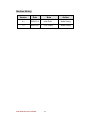
Revision History
Version
Date
Note
Author
0.1
2008.02.12
Initial Draft
Aladin Huang
1.0
2008.02.21
First Version
Aladin Huang
I530 Motherboard User Manual
VII
Contents
CHAPTER 1
GENERAL INFORMATION ................................ .....1
1.1
INTRODUCTION ............................................................................ 1
1.2
1.3
1.4
FEATURE ..................................................................................... 1
MOTHERBOARD SPECIFICATIONS .................................................. 2
FUNCTION BLOCK ....................................................................... 3
1.5
BOARD DIMENSIONS .................................................................... 4
CHAPTER 2
INSTALLATIONS ................................ ...................... 6
2.1
MEMORY MODULE(SO-DIMM)INSTALLATION ........................ 6
2.2
2.3
I/O EQUIPMENT INSTALLATION .................................................... 6
JUMPERS AND CONNECTORS ........................................................ 8
2.4
2.5
3.1
JUMPER SETTING ....................................................................... 10
CONNECTORS AND PIN ASSIGNMENT .......................................... 12
GRAPHIC DRIVER INSTALLATION ................................................ 20
CHAPTER 4
CHIPSET DRIVER INSTALLATION .................... 24
4.1
CHIPSET DRIVER INSTALLATION ................................................. 24
CHAPTER 5 ETHERNET DRIVER INSTALLATION ................. 29
5.1
INSTALLATION OF ETHERNET DRIVER ......................................... 29
CHAPTER 6
AUDIO DRIVER INSTALLATION ........................ 33
6.1
6.2
INTRODUCTION ....................................................................... 33
INSTALLATION OF AUDIO DRIVER ............................................. 33
CHAPTER 7 AWARD BIOS INSTALLATION ................................ .36
7.1
7.2
7.3
BIOS INTRODUCTION .............................................................. 36
BIOS SETUP ........................................................................... 36
STANDARD CMOS SETUP ........................................................ 37
7.4
7.5
7.6
ADVANCE BIOS FEATURE ....................................................... 39
ADVANCED CHIPSET FEATURE ................................................. 42
INTEGRATED PERIPHERALS .................................................... 45
7.7
7.8
7.9
POWER MANAGEMENT SETUP ................................................ 47
PNP / PCI CONFIGURATION .................................................... 50
PC HEALTH STATUS ............................................................... 51
7.10
7.11
LOAD FAIL-SAFE DEFAULTS .................................................. 52
LOAD OPTIMIZED DEFAULTS ................................................ 52
I530 Motherboard User Manual
VIII
7.12
7.13
7.14
SET SUPERVISOR PASSWORD .................................................. 52
SAVE & EXIT SETUP .............................................................. 52
EXIT WITHOUT SAVING ......................................................... 52
NOTE: DIGITAL I/O SAMPLE CODE ................................ ............. 53
I530 Motherboard User Manual
IX
CHAPTER
General Information
1
This chapter includes I530 Motherboard background
information.
Sections include:
Introduction
Feature
Motherboard Specification
Function Block
Board Dimensions
I530 Motherboard User Manual
1
Chapter 1
1.1
General Information
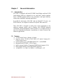
Introduction
I530 SBC is equipped with Intel 855GME North Bridge and Intel ICH4
South Bridge which are designed for use with Intel’s mobile platform.
Intel’s 855GME platform delivers the performance and high scalability
cutting-edge embedded computing application.
In peripheral connectivity, I530 SBC with one Mini-PCI I/O ports, one
PATA connector, one Digital I/O and two Hi-Speed USB connectors.
Thus, I530 SBC is designed to satisfy most of the applications in the
industrial computer market, such as Gaming, POS, KIOSK, Industrial
Automation, and Programmable Control System. It is a compact design to
meet the demanding performance requirements of today’s business and
industrial applications.
1.2
Feature
3.5-inch Form Factor ( 146mm x 101mm)
Supports Socket FC-PGA 478/FC-BGA 479 Intel® Pentium M /
Celeron M processors
System memory up to 1GB DDR 200/266/333, 1xSO-DIMM
Integrated Intel 855GME + ICH4 Chipset
Intel® extreme Graphics 2 Integrated 64MB shared supports VGA
Dual Gigabit Ethernet ( Dual Fast Ethernet optional)
1 x Mini PCI, 2 x COM, 2 x USB2.0, 1 x PATA and 1 x CF
I530 Motherboard User Manual
1
1.3
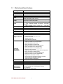
Motherboard Specifications
CPU Type
CPU FSB
CPU Socket
Chipset
BIOS
VGA
LVDS
LAN
Memory Type
LPC I/O
Keyboard/Mouse
IDE Interface
Sound
USB
Edge Connectors
On Board
Pin-Header
Connectors
Power Connector
Expansion Slots
Form Factor
Dimensions
Mechanical &
environmental
Intel l® Pentiun M/ Celeron M Processor
400 MHz
Intel Socket FC-PGA 478/ FC-BGA 479
Intel 855GME / ICH4
Award 4Mbit Flash
Intel® extreme Graphics 2
64MB shared with system memory
Intel® 82855GME built in single- or Dual-channel panel
support up to 1600 x 1200, 24bit
2 x Giga LAN (Dual Realtek RTL8110SCL Controller )
2 x Fast LAN(Dual Realtek RTL8110C L Controller)
(optional)
1 x DDR SO-DIMM socket, supports up to 1GB DDR
200/266/333 SDRAM
Winbond W83627EHG integrated hardware monitoring
1 x PS/2 Keyboard/Mouse connectors
One channels; supports Ultra DMA 33/66/100
Realtek ALC655 (Line-in, Line-out, Mic in)
6 ports, USB 2.0 (4 x USB Connector, 2 x USB pin-header )
1 x +12V DC-IN Jack
1 x PS/2 connector for keyboard/mouse
1 x VGA out connector
2 x Gigabit LAN RJ-45
1 x dual USB stack connector
1 x 44 pins box-header
1 x 10pins pin-header for Front Panel(2x5)
1 x 3pins pin-header for CPU Fan
1 x 3pins pin-header for System FAN
1 x 8pins pin-header for 5V/12V external power
1 x 2pins pin-header for 5V external power
1 x 2pins pin-header for 12V external power
1 x 4pins ATX 12V connector
1 x 10pins pin-header for Front Audio( without Amp.)(2x5)
1 x 8pins pin-header for USB 3/4(2x4)
2 x 10pins pin-header for COM1/2 (RS232)(2x5)
1 x 5pins pin-header for COM1 (RS422/485)
1 x 40pins DF13 Connector for LVDS
1 x 3pins digital panel backlight brightness controller
1 x 7pins digital panel backlight controller
1 x 10pins pin-header for DIO(2x5)
Input: 4-pin ATX 12V Power input
1 x Mini-PCI, 1 x CF Card Type I/II
3.5 inch
146mm x 101mm
Operating temperature: 0 deg. C to 60 deg. C
Operating Humidity: 30 ~ 90% Relative humidity,
non-condensing
Certification: CE, FCC, RoHS
I530 Motherboard User Manual
2
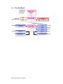
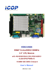
1.4
Function Block
Pentium M /
Celeron M
Processor
Mobile CPU
Banias
FSB 400
1600*1200
18/24bit Dual CH
CRT
Intel 855GME
LVDS
DIMM x 1
DDR2 533/400 Max.1GB
66MHz Hub Interface 1.5
ATA100
33MHz
1 x IDE Host
Intel ICH4
LAN
2x 1GB/s
USB
480MB/s
Mini PCI
RTL ALC655
Audio
Realtek ALC655W83267EHG
Super IO
Realtek ALC655
ROM FWH
Realtek ALC655
Secondary IO Fintek 81216D
Realtek ALC655
I530 Motherboard User Manual
3
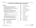
1.5
Board dimensions
I530 Motherboard User Manual
4
CHAPTER
Installations
2
This chapter provides information on how to use the
jumps and connectors on I530 Motherboard.
The Sections include:
Memory Module Installation
I / O Equipment Installation
Setting the Jumpers
Connectors on I530 Motherboard
I530 Motherboard User Manual
5
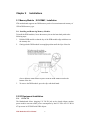
Chapter 2
Installations
2.1 Memory Module(SO-DIMM)Installation
I530 motherboard supports one DDR memory socket for a maximum total memory of
1GB in DDR memory type.
2.1.1 Installing and Removing Memory Modules
To install the DDR modules, locate the memory slot on the board and perform the
following steps:
1. Hold the DDR module so that the key of the DDR module align with those on
the memory slot.
2. Gently push the DDR module in an upright position until the clips of the slot
3.
close to hold the DDR module in place when the DDR module touches the
bottom of the slot.
To remove the DDR module, press the clips with both hands.
2.2 I/O Equipment Installation
2.2.1 12V DC-IN
The Motherboard allows plugging 12V DC-IN jack on the board without another
power module converter under power consumption by Intel FC-PGA 478/ FC-BGA
479 processor in 855GME with ICH4 chipset.
I530 Motherboard User Manual
6
2.2.2 PS/2 Keyboard and PS/2 Mouse
The Motherboard provides one PS/2 interface. The PS/2 connector supports Keyboard
and Mouse. In other cases, espec ially in embedded applications, a mouse is not used.
Therefore, the BIOS standard setup menu allows you to select* “All, But Keyboard”
under the “Halt On”. This allows no -keyboard operation in embedded system
applications without the system halting under P OST.
2.2.3 Serial COM ports
Two RS-232 connectors build in the rear I/O . one optional COM1 ports support
RS-232/422/485. When an optional touch-screen is ordered with PPC, serial com port
can connect to a serial or an optional touch -screen.
2.2.4 Internal VGA
The Motherboard has one VGA port that can be connected to an external CRT/ LCD
monitor. Use VGA cable to connect to an external CRT / LCD monitor, and connect
the power cable to the outlet . The VGA connector is a standard 15 -pin D-SUB
connector.
2.2.5 Ethernet interface
The Motherboard is equipped with Dual Realtek RTL8110SCL or ( Realtek
RTL8110CL 10/100 Mbps ) chipsets which is fully compliant with the PCI
10/100/1000 Mbps Ethernet protocol compatible. It is supported by major network
operating systems. The Ethern et ports provide two standard RJ-45 jacks.
2.2.6 USB ports
Four USB devices (two with pin headers) may be connected to the system though an
adapter cable. Various adapters may come with USB ports. USB usually connect the
external system to the system. The USB p orts support hot plug-in connection.
Whatever, you should install the device driver before you use the device.
2.2.7 Audio Jack ( Pin-header)
The Audio 5.1 channel capabilities are provided by a Realtek ALC655 chipset
supporting digital audio outputs. The audio interface includes Mic-in,: line-in and
line-out.
I530 Motherboard User Manual
7
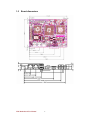
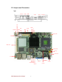
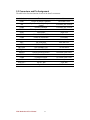
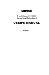
2.3 Jumpers and Connectors
TOP
LAN2
LAN1 USB
VGA
PS/2
+12V DC
JP3
CON1
JP2
PANEL1
USB2
CON3
J7
IDE1
NB_FAN1
CON2
Mini-PCI
CPU_FAN1
CON8
ATX 12V1
J4
VGA1
CON6 JP4
CON4
I530 Motherboard User Manual
8
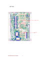
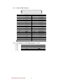
PSKBM1 CON9
CON5
BOTTOM
Memory socket
CF slot
I530 Motherboard User Manual
9
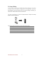
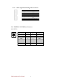
2.4 Jumper Setting
A pair of needle-nose pliers may be helpful when working with jumper s. If you have
any doubts about the best hardware configuration for your application, contact your
local distributor or sales representative before you make any changes. Generally, you
simply need a standard cable to make most connections.
The jumper setting diagram is as below. If a jumper shorts pin 1 and pin 2, the setting
diagram is shown as the right one.
1
2
3
The following tables list the function of each of the board's jumpers.
Label
Function
Note
JP3
Clear CMOS
3x1 header , pitch 2.0mm
JP4
RS232 / RS422 / RS485 Selector
2x3 header , pitch 2.0mm
CON3
LVDS VOLTAGE
2x3 header , pitch 2.0mm
I530 Motherboard User Manual
10
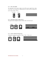
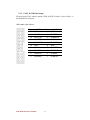
2.4.1 JP3: Clear CMOS
User must make sure the power supply to turn off the power supply before setting
Clear CMOS. Users remember to setting jumper back to Norm al before turning on the
power supply. Default: 2short3.
Clear CMOS
Normal
1
1
2
2
3
3
Pin No.
1 Short 2
2 Short 3
Functions
Clear CMOS
Normal
2.4.2 JP4: RS232 / RS422 / RS485 Selector
The jumper can be configured to operate COM1 in RS-232/422/485 mode.
RS232
RS422
RS485
1
2
1
2
1
2
3
4
3
4
3
4
5
6
5
6
5
6
Pin No.
1 Short 2
3 Short 4
5 Short 6
Functions
RS232
RS422
RS485
2.4.3 CON3: LCD Panel Voltage Select
CON3 can be configured to operate in 3.3Volts / 5Volts / 12Volts mode.
3.3Volts
5Volts
12Volts
1
2
1
2
1
2
3
4
3
4
3
4
5
6
5
6
5
6
I530 Motherboard User Manual
Pin No.
1 Short 2
3 Short 4
5 Short 6
11
Functions
3.3Volts Selected
5Volts Selected
12Volts Selected
2.5 Connectors and Pin Assignment
The table below lists the function of each of the board’s connectors.
Label
Function
Note
CON1
DF13-40DP-1.25V
3x1 header, pitch 2.54mm
CON2
LVDS LCD Output Connector
Digital Panel Backlight Brightness
Control
Inverter Connecter
PSKBM1
PS2 Keyboard/Mouse Connector
Mini-DIN
VGA1
VGA Output
15pin VGA
CON5
COM1/COM2 for RS232
2x5 header
CON6
COM1 for RS422/485
1x5 header
J4
Audio Jack
3 Audio I/O
IDE1
IDE Connector
44Pin IDE Conn.
USB2
USB PIN HEADER
4x2 Pin Header
NB_FAN1
FAN CONNECTOR
3x1 Pin Header
CPU_FAN1
FAN CONNECTOR
3x1 Pin Header
PANEL1
System Function Connector
5x2 header ,pitch 2.0mm
CON8
12V External Power
2x1 header, pitch 2.0mm
CON9
5V External Power
2x1 header, pitch 2.0mm
J7
12V/5V External Power
4x2 header ,pitch 2.54mm
ATX 12V 1
12V DC Jack
4 Pin Jack
CON4
Digital I/O
2x5 Pin header
JP2
I530 Motherboard User Manual
12
7x1 header, pitch 2.54mm
2.5.1
CON1: LVDS Connector
Pin No.
1
3
5
7
9
11
13
15
17
19
21
23
25
27
29
31
33
35
37
39
2.5.2
SYMBOL
LCDVDD
LCDVDD
LCDVDD
GND
GND
GND
GND
GND
GND
GND
GND
GND
GND
GND
GND
GND
GND
GND
GND
GND
Pin No.
2
4
6
8
10
12
14
16
18
20
22
24
26
28
30
32
34
36
38
40
SYMBOL
LVDS_LTX0LVDS_LTX0+
LVDS_LTX1LVDS_LTX1+
LVDS_LTX2LVDS_LTX2+
LVDS_LCLKLCDS_LCLK
NC
NC
LVDS_UTX0LVDS_UTX0+
LVDS_UTX1LVDS_UTX1+
LVDS_UTX2LVDS_UTX2+
LVDS_UCLKLVDS_UCLK
NC
NC
JP2: Digital Panel Backlight Brightness Control
Pin No.
1
2
3
I530 Motherboard User Manual
SYMBOL
VCC
Black Light Control
GND
13
2.5.3
CON2: Digital Panel Backlight Inverter Power
Pin No.
1
2
3
4
5
6
7
2.5.4
SYMBOL
+12V
+12V
+12V
GND
Black Light Control
GND
Black Light EN 5V
PSKBM1: PS2 K/B Mouse Connector
6-pin Mini Din
Signal Name
Keyboard
Mouse
Signal Name
Keyboard data
1
1
Mouse data
N.C.
2
2
N.C.
GND
3
3
GND
5V
4
4
5V
Keyboard clock
5
5
Mouse clock
N.C.
6
6
N.C.
I530 Motherboard User Manual
14
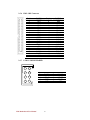
2.5.5 CON5: D-SUB Dual Output
The serial port CON5, which is option COM1 for RS232 (from 11 pin to 20 pin) , is
the Winbond I/O serial port.
10x2 header, pitch 2.0mm
Pin No.
SYMBOL
20
GND
Pin No.
SYMBOL
19
GND
18
FK NRI2
17
FK NDTR2
16
FK NCTS2
15
FK NSOUT2
14
FK NRTS2
13
FK NSIN2
12
FK NDSR2
11
FK NDCD2
10
GND
9
GND
8
FK NRI1
7
FK NDTR1
6
FK NCTS1
5
FK NSOUT1
4
FK NRTS1
3
FK NSIN1
2
FK NDSR1
1
FK NDCD1
I530 Motherboard User Manual
15
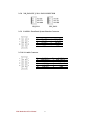
2.5.6
1
IDE1: IDE Connector
Pin No.
1
3
5
7
9
11
13
15
17
19
21
23
25
27
29
31
33
35
37
39
41
43
2
44
2.5.7
SYMBOL
RESET
DD7
DD6
DD5
DD4
DD3
DD2
DD1
DD0
GND1
DREQ
DIOW#
DIOR#
IO_RDYD
DACK#
IRQ
DA1
DA0
DCS#1
DASP#
+5V1
GND
Pin No.
2
4
6
8
10
12
14
16
18
20
22
24
26
28
30
32
34
36
38
40
42
44
SYMBOL
GND3
DD8
DD9
DD10
DD11
DD12
DD13
DD14
DD15
NC
GND4
GND5
GND6
CSEL
GND7
IOCS16#
CBL_ID#
DA2
DCS#3
GND8
+5V2
NC
USB2: USB PIN HEADER
2
1
4
3
6
5
8
7
I530 Motherboard User Manual
Pin
2
4
6
8
USB2
SYMBOL
Pin
USBVCC
1
USB_P63
USB_P6+
5
GND
7
16
SYMBOL
USBVCC
USB_P7USB_P7+
GND
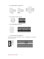
2.5.8
NB_FAN1/CPU_FAN1: FAN CONNECTOR
NB_FAN1
2.5.9
2
4
6
8
10
CPU_FAN1
PANEL1: Front Panel System Function Connector
1
3
5
7
9
Pin
2
4
6
8
10
SYMBOL
HD_LED+
HD_LEDRT_BT1
RT_BT2
5VSB
Pin
1
3
5
7
9
SYMBOL
PW_LED+
PW_LEDPW_BT1
PW_BT2
RSEV
2.5.10 J4: Audio Connector
2
4
6
8
10
1
3
5
7
9
I530 Motherboard User Manual
Pin
2
4
6
8
10
SYMBOL
LINE OUT L
GND
LINE IN L
MICVREF
VOL OUT
17
Pin
1
3
5
7
9
SYMBOL
LINE_OUT R
GND
LINE IN R
MIC1
GND
2.5.11 CON8/CON9/J7: External Power
CON8
CON9
J7
2.5.12 ATX12V1: 12V DC Connector
Pin
1
2
3
4
SYMBOL
Ground
Ground
+12V
+12V
2.5.13 CON4: Digital I/O Connector
2
4
6
8
10
Pin
2
4
6
8
10
1
3
5
7
9
SYMBOL
Vcc
Out1
Out0
IN1
IN0
Pin
1
3
5
7
9
SYMBOL
GND
Out3
Out2
IN3
IN2
2.5.13 CON6: RS-422 / RS-485 Header
Pls note that our I530 the COM1: RS232
transfer
RS422/RS485 are using different
socket and different cable
1
422 RX2-
Pin No.
2
422 RX2+
3
485TXRX2-
4
485TXRX2+
5
Gnd
1
2
3
4
5
I530 Motherboard User Manual
SYMBOL
422 RX2422 RX2+
485 TXRX2485TXRX2+
Gnd
18
CHAPTER
3
Graphic Driver Installation
This chapter offers information on the chipset software
Installation utility
Installation of Graphic Driver
Panel Resolution Setting
I530 Motherboard User Manual
19
3.1 Graphic Driver Installation
I530 Motherboard is equipped with Intel 855GME / ICH4 Companion Device.
The Intel Graphic Drivers shou ld be installed first, and it will enable “Video
Controller (VGA compatible). Follow the instructions below to complete the
installation. You will quickly complete the installation.
Step.1. Insert the CD that comes with the Motherboard. Open the file
document “Graphic Driver “.
Step.2. Click on “win2K_xp141950” to execute the setup.
I530 Motherboard User Manual
20
Step.3. Click on “Next “ to install Driver.
Step.4. Click on “Next “ to install Driver.
I530 Motherboard User Manual
21
Step.5. Click on “Yes “ to agree License.
Step.7. Click on “Yes, I want to restart this computer now “ to go on.
I530 Motherboard User Manual
22
CHAPTER
4
Chipset Driver Installation
This chapter offers information on the chipset software
Installation utility
Installation of Chipset Driver
Further information
I530 Motherboard User Manual
23
Chapter 4
4.1
Chipset Driver Installation
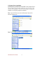
Chipset Driver Installation
Setp.1. Insert the CD that comes with the motherboard. Open the file document
“Chipset Driver”.
Setp.2. Click on “Setup“ to install driver.
I530 Motherboard User Manual
24
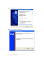
Setp.3. Click on “Next“ to install driver.
Setp.4. Click on “Yes “ to agree License
I530 Motherboard User Manual
25
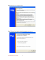
Setp.5. Click on “Next“ to install driver.
Setp.6. Click on “Next“ to install driver.
I530 Motherboard User Manual
26
Step.7. Click on “Yes, I want to restart this computer now “ to go on.
I530 Motherboard User Manual
27
CHAPTER
5
Ethernet Driver Installation
This chapter offers information on the Ethernet software
installation utility.
Sections include:
Introduction
Installation of Ethernet Driver
I530 Motherboard User Manual
28
Chapter 5
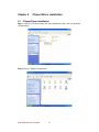
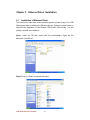
5.1
Ethernet Driver Installation
Installation of Ethernet Driver
The Users must make sure which operating system you are using in the I530
Motherboard before installing the Ethernet drivers. Follow the steps below to
complete the installation of the Realtek RTL8110SC LAN drivers. You will
quickly complete the installation.
Step.1. Insert the CD that comes with the moth erboard. Open the file
document “LAN Driver”.
Step.2 Click on “Setup” to execute the setup.
I530 Motherboard User Manual
29
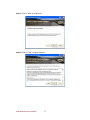
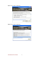
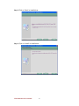
Step.3. Click on “Next“ to install driver.
Step.3. Click on “Install“ to install driver.
I530 Motherboard User Manual
30
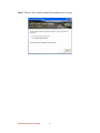
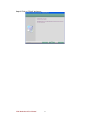
Setp.3. Click on “Finish“ and go on.
I530 Motherboard User Manual
31
CHAPTER
6
Audio Driver Installation
This chapter offers information on the Audio software
installation utility.
Sections include:
Introduction
Installation of Audio Driver
I530 Motherboard User Manual
32
Chapter 6
6.1
Audio Driver Installation
Introduction
The I530 Motherboard is equipped with the ALC655 is a 16-bit, full-duplex AC'97 Rev.
2.3 compatible six-channel audio CODEC designed for PC multimedia systems,
including host/soft audio and AMR/CNR -based designs..
The ALC655 CODEC provides three pairs of stereo outputs with 5 -bit volume control,
a mono output, and multiple stereo and mono inputs, along with flexible mixing, gain,
and mute functions to provide a complete integrated audio solution for PCs.
6.2 Installation of Audio Driver
The users must make sure which operating system you are using in the I530 Motherboard
before installing the Audio drivers. Follow the steps below to complete the installation of the
Realtek ALC655 Audio drivers. You will quickly complete the installation.
Step.1. Insert the CD that comes with the motherboard. Open the file document
“alc655_driver” and click on “WDM_A400” to execute the setup.
I530 Motherboard User Manual
33
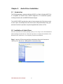
Step.2. Click on “Next“ to install driver.
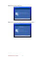
Step.3. Click on “Yes, I want to restart my computer now ” to finish installation.
I530 Motherboard User Manual
34
CHAPTER
7
Award BIOS Installation
This chapter describes the different settings available in
the Award BIOS that comes with the board. This chapter
offers information on the Award BIOS installation utility.
Sections include:
BIOS Introduction
BIOS Setup
Standard CMOS Setup
Advanced BIOS Features
Advanced Chipset Features
Integrated Peripherals
Power Management Setup
PC Health Status
Load Fail-Safe Defaults
Load Optimized Defaults
Set Supervisor/User Password
Save & Exit Setup
Exit Without Saving
I530 Motherboard User Manual
35
Chapter 7 Award BIOS Installation
7.1 BIOS Introduction
Award BIOS (Basic Input/Output System) installed in your computer system’s ROM
supports Intel processors. The BIOS provides critical low -level support for a standard
device such as disk drives, serial ports and parallel ports. It also adds virus and
password protection as well as special s upport for detailed fine-tuning of the chipset
controlling the entire system.
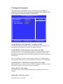
7.2 BIOS Setup
The Award BIOS provides a Setup u tility program for specifying the system
configurations and settings. The BIOS ROM of the syste m stores the Setup utility. As
you turn on the computer, the Award BIOS is immediately activated. Pressing the
<Del> key immediately allows you to enter the Setu p utility. If you are a little bit late
pressing the <Del> key, POST (Power On Self Test) will continue with its test
routines, thus preventing you from invoking the Setup. If you still wish to enter Setup,
restart the system by pressing the ”Reset” button or simultaneously pressing the
<Ctrl>, <Alt> and <Delete> keys. You can also restart by turning the system Off and
back On again. The following message will appear on the screen:
I530 Motherboard User Manual
36
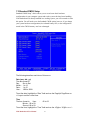
7.3 Standard CMOS Setup
Standard CMOS Setup” choice allows you to record some basic hardware
configurations in your computer system and set the system clock and error handling.
If the motherboard is already installed in a working system, you will not need to select
this option. You will need to run the Standard CMOS option, however, if you change
your system hardware configurations, the onboard battery fails, or the configuration
stored in the CMOS memory was lost or damaged.
The following describes each item of this me nu.
Date (mm : dd : yy)
The date format is:
Day :
Sun to Sat
Month : 1 to 12
Date : 1 to 31
Year : 1999 to 2099
To set the date, highlight the “Date” field and use the PageUp/ PageDown or
+/- keys to set the current time.
Time
The time format is:
Hour
:
00 to 23
Minute : 00 to 59
Second : 00 to 59
To set the time, highlight the “Time” field and use the <PgUp>/ <PgDn> or +/ I530 Motherboard User Manual
37
keys to set the current time.
IDE Channel Master/Slave
The onboard PCI-IDE connector provides one channel for connecting up to
one IDE hard disks or other IDE device .
Press <Enter> to configure the hard disk. The se lections include None, Auto,
and Manual. Select ‘Manual’ to define the drive information manually. You will
be asked to enter the following items.
Cylinder :
Number of cylinders
Head :
Number of read/write heads
Precomp :
Write precompensation
Landing Zone :
Landing zone
Sector :
Number of sectors
Video
This field selects the type of video display card installed in your system. You
can choose the following video display cards:
EGA/VGA
For EGA, VGA, SEGA, SVGA
or PGA monitor adapters. (default)
CGA 40
Power up in 40 column mode.
CGA 80
Power up in 80 column mode.
MONO
For Hercules or MDA adapters.
Halt On
This field determines whether or not the system will halt if an error is detected
during power up.
No errors
The system boot will not be halted for any error that may be
detected.
All errors
Whenever the BIOS detects a non -fatal error, the system will stop
and you will be prompted.
All, But Keyboard
The system boot will not be halted for a keyboard error; it will stop
for all other errors
I530 Motherboard User Manual
38
7.4 Advance BIOS Feature
This section allows you to configure and improve your system and allows you
to set up some system features according to your preference.
CPU Feature
Press Enter to configure the settings relevant to CPU Fea ture.
Hard Disk Boot Priority
With the field, there is the option to choose, aside from the hard disks
connected, “Bootable add -in Cards” which refers to other external devices.
Virus Warning
If this option is enabled, an alarm message will be displayed when trying to
write on the boot sector or on the partition table on the disk, which is typical of
the virus.
CPU L1 and L2 Cache
Cache memory is additional memory that is faster than conventional DRAM
(system memory). CPUs from 486 -type on up contain internal cache memory,
and most, but not all, modern PCs have additional (external) cache memory.
When the CPU requests data, the system transfers the requested data from
the main DRAM into cache memory, for even faster access by the CPU. These
allow you to enable (speed up memory access) or disable the cache function.
Quick Power On Self Test
When enabled, this field speeds up the Power On Self Test (POST) after the
system is turned on. If it is set to Enabled, BIOS will skip some items.
First Boot Device
I530 Motherboard User Manual
39
These fields determine the drive that the system searches first for an operating
system. The option available include Floppy, LS120, Hard Disk, CDROM,
ZIP100, USB-Floppy, USB-ZIP, USB-CDROM, LAN and Disable.
Boot Other Device
These fields allow the system to search for an OS from other devices other
than the ones selected in the First/Second/Third Boot Device.
Boot Up Floppy Seek
This feature controls whether the BIOS checks for a floppy drive while booting
up. If it cannot detect one (either due to i mproper configuration or its absence),
it will flash an error message.
Boot Up NumLock Status
This allows you to activate the NumLock function after you power up the
system.
Gate A20 Option
This field allows you to select how Gate A20 is worked. Gate A2 0 is a device
used to address memory above 1 MB.
Typematic Rate Setting
When disabled, continually holding down a key on your keyboard will generate
only one instance. When enabled, you can set the two typematic controls listed
next. By default, this field is set to Disabled.
Typematic Rate (Chars/Sec)
When the typematic rate is enabled, the system registers repeated keystrokes
speeds. Settings are from 6 to 30 characters per second.
Typematic Delay (Msec)
When the typematic rate is enabled, this i tem allows you to set the time interval
for displaying the first and second characters. By default, this item is set to
250msec.
Security Option
This field allows you to limit access to the System and Setup. The default value
is Setup. When you select Sys tem, the system prompts for the User Password
every time you boot up. When you select Setup, the system always boots up
and prompts for the Supervisor Password only when the Setup utility is called
up.
APIC Mode
APIC stands for Advanced Programmable Inter rupt Controller. The default
setting is Enabled.
MPS Version Control for OS
This option is specifies the MPS (Multiprocessor Specification) version for your
I530 Motherboard User Manual
40
operating system. MPS version 1.4 added extended configuration tables to
improve support for multi ple PCI bus configurations and improve future
expandability. The default setting is 1.4.
OS Select for DRAM > 64MB
This option allows the system to access greater than 64MB of DRAM memory
when used with OS/2 that depends on certain BIOS calls to access m emory.
The default setting is Non -OS/2.
I530 Motherboard User Manual
41
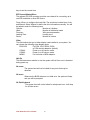
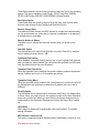
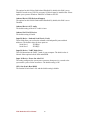
7.5 Advanced Chipset Feature
This Setup menu controls the configuration of the chipset.
Phoenix - AwardBIOS CMOS Setup Utility
Advanced Chipset Features
X
X
X
X
DRAM Timing Selectable
CAS Latency Time
DRAM RAS# to CAS# Delay
DRAM RAS# Precharge
Precharge delay (tRAS)
MGM Core Frequency
System BIOS Cacheable
Video BIOS Cacheable
Memory Hole At 15-16M
Delayed Transaction
Delay Prior to Thermal
AGP Apertrue Size
[By SPD]
2.5
3
3
8
[Auto Max 266MHz]
[Enabled]
[Disabled]
[Disabled]
Item Help
Menu Level ►
↑↓→←:Move
Enter:Select +/-/PU/PD:Value F10:Save Esc:Exit F1:Genenal Help
F5: Previous Values
F6: Fail -Safe Defaults F7: Optimized Defaults
DRAM Timing Selectable
This option refers to the method by which the DRAM timing is selected. The
default is By SPD.
CAS Latency Time
You can configure CAS latency time in HCLKs as 2 or 2.5 or 3. The system
board designer should set the values in this field, depending on the DRAM
installed. Do not change the values in this field unless you change
specifications of the installed DRAM or the installed CPU.
DRAM RAS# to CAS# Delay
This option allows you to insert a delay between the RAS (Row Address Strobe)
and CAS (Column Address Strobe) si gnals. This delay occurs when the
SDRAM is written to, read from or refreshed. Reducing the delay improves the
performance of the SDRAM.
DRAM RAS# Precharge
This option sets the number of cycles required for the RAS to accumulate its
charge before the SDR AM refreshes. The default setting for the Active to
Precharge Delay is 4.
I530 Motherboard User Manual
42
DRAM Data Integrity
This BIOS feature controls the ECC feature of the memory controller. ECC,
which stands for Error Checking and Correction , enables the memory
controller to detect and correct single-bit soft memory errors. The memory
controller will also be able to detect double -bit errors although it will not be able
to correct them. This provides increased data integrity and system stability.
However, this feature can only be en abled if you are using special ECC
memory modules.
MGM Core Frequency
This field sets the frequency of the DRA M memory installed. The default
setting is Auto Max 266MHz.
System BIOS Cacheable
The setting of Enabled allows caching of the system BIOS ROM a t
F000h-FFFFFh, resulting in better system performance. However, if any
program writes to this memory area, a system error may result.
Video BIOS Cacheable
The Setting Enabled allows caching of the video BIOS ROM at
C0000h-F7FFFh, resulting in better vid eo performance. However, if any
program writes to this memory area, a system error may result.
Memory Hole At 15M-16M
In order to improve performance, certain space in memory can be reserved for
ISA cards. This memory must be mapped into the memory spac e below 16
MB. The choices are Enabled and Disabled.
Delayed Transaction
It's highly recommended that you enable Delayed Transaction for better PCI
performance and to meet PCI 2.1 specifications. Disable it only if your PCI
cards cannot work properly with this option or if you are using an ISA card that
is not PCI 2.1 compliant.
Delay Prior to Thermal
The Delay Prior To Thermal BIOS feature controls the activation of the
Thermal Monitor's automatic mode. It allows you to determine when the
Pentium 4's Thermal Monitor should be activated in automatic mode after the
system boots. For example, with the default value of 16 Minutes, the BIOS
activates the Thermal Monitor in automatic mode 16 minutes after the system
starts booting up.
AGP Aperture Size(MB)
This BIOS feature allows you to select the size of the AGP aperture. The
aperture is a portion of the PCI memory address range dedicated as graphics
memory address space. Host cycles that hit the aperture range are forwarded
to the AGP without need for transl ation. The aperture size also determines the
maximum amount of system RAM that can be allocated to the graphics card
for texture storage. The default setting is 64MB.
I530 Motherboard User Manual
43
On-Chip VGA Setting
The fields under the On-Chip VGA Setting and their default settings are:
Enable
On-Chip Frame Buffer Size:
The default setting is 32 MB
Boot Display:
You could select Auto/CRT/LVDS1/LVDS1+CRT. The default setting is A uto
Panel Scaling:
The default setting is A uto
Panel Number
These fields allow you to select the LCD Panel type.
640*480 18bit SC
800*480 18bit SC
800*600 18bit SC
1024*768 18bit SC
1024*768 24bit SC
1280*800 18bit SC
1280*1024 24bit DC
1366*768 24 bit SC
1440*900 24bit DC
1400*1050 24bit SC
1600*1200 24bit DC
1920*1080 24bit DC
1920*1200 24bit DC
I530 Motherboard User Manual
44
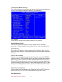
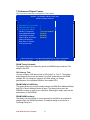
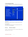
7.6 Integrated Peripherals
This section sets configurations for your hard disk and other integrated
peripherals. The first screen shows three main items for user to select. Once
an item selected, a submenu appears. Details follow.
Phoenix - AwardBIOS CMOS Setup Utility
Integrated Peripherals
OnChip IDE Device
Onboard Device
SuperIO Device
GiGA Lan Boot ROM
GiGA Lan1 Boot ROM
:Move Enter : Select
F5: Previous Values
↑↓→ ←
[ Press Enter ]
[ Press Enter ]
[ Press Enter ]
[ Enable ]
[ Enable ]
Item Help
Menu Level
+/-/PU/PD:Value
F10:Save
F6: Fail-Safe Defaults
ESC: Exit
F1:General Help
F7: Optimized Defaults
On Chip IDE Device / On Chip Primary / Secondary PCI IDE
The integrated peripheral controller contains an IDE interface with support for two
IDE channels. Select Enabled to activate each channel separately.
On Chip IDE Device /IDE Primary/Secondary Master/Sla ve PIO
These fields allow your system hard disk controller to work faster. Rather than have
the BIOS issue a series of commands that transfer to or from the disk drive, PIO
(Programmed Input/Output) allows the BIOS to communicate with the controller and
CPU directly.
The system supports five modes, numbered from 0 (default) to 4, which primarily
differ in timing. When Auto is selected, the BIOS will select the best available mode.
On Chip IDE Device / IDE Primary/Secondary Master/Slave UDMA
These fields allow your system to improve disk I/O throughput to 33Mb/sec with the
Ultra DMA/33 feature. The options are Auto and Disabled.
Onboard Device/ USB Controller
The options for this field are Enabled and Disabled. By default, this field is set to
Enabled.
Onboard Device/USB 2.0 Controller
I530 Motherboard User Manual
45
The options for this field are Enabled and Disabled. By default, this field is set to
Enabled. In order to use USB 2.0, necessary OS drivers must be installed first. Please
update your system to Windows 2000 SP4 or Windo ws XP SP1.
Onboard Device/USB Keyboard Support
The options for this field are Enabled and Disabled. By default, this field is set to
Disabled.
Onboard Device/AC97 Audio
The default setting of the AC97 Audio is Auto.
Onboard LAN/LAN1 Devices
The default setting is Enable.
SuperIO Device / Onboard Serial Port1 ( Port2)
These fields allow you to select the onboard serial and parallel ports and their
addresses. The default values for these ports are:
Serial Port 1
3F8/IRQ4
Serial Port 2
2F8/IRQ3
SuperIO Device / UART Mode Select
This field determines the UART 2 mode in your computer. The default value is
Normal. Other options include IrDA and ASKIR.
Super IO Device / Power On After Fail
The setting configures the system power on status when power is re stored to the
system after a power failure occurrence. The default setting is Off.
GiGA Lan (Lan1) Boot ROM
The function is boot from LAN, and the default setting is disable.
I530 Motherboard User Manual
46
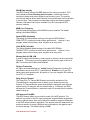
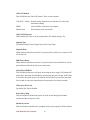
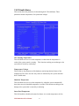
7.7 Power Management Setup
This section sets configurations for your Power Management function setting. The
screen shows some items for user to select. Once an item selected, a submenu appears.
Details follow.
Phoenix - AwardBIOS CMOS Setup Utility
Power Management Setup
ACPI function
ACPI Suspend Type
Power Management
Video Off Method
Video Off In Suspend
Suspend Mode
HDD Power Down
Soft-Off by PWR-BTTN
Wake-Up by PCI card
Run VGABIOS if S3 Resume
Power On by Ring
Resume by Alarm
X Date(of Month) Alarm
X Time(hh:mm:ss) Alarm
[Enabled]
[S1(POS)]
[User Define]
[V/H SYNC+Blank]
[Yes]
[Disabled]
[Disabled]
[Delay 4 Sec.]
[Enabled]
[Auto]
[Enabled]
[Disabled]
0
0: 0: 0
Item Help
Menu Level ►
↑↓→←:Move
Enter:Select +/-/PU/PD:Value F10:Save Esc:Exit F1:Genenal Help
F5: Previous Values
F6: Fail -Safe Defaults F7: Optimized Defaults
ACPI Function
Enable this function to support ACPI (Advance Configuration and Power Interface).
Power Management
This field allows you to select the type of power saving management modes. There
are two selections for Power Management.
Min. Saving
Max. Saving
User Define
Minimum power management
Maximum power management.
Each of the ranges is from 1 min. to 1hr. Except for HDD Power Down
which ranges from 1 min. to 15 min.
I530 Motherboard User Manual
47
Video Off Method
This field defines the Video Off features. There are three options.
V/H SYNC + Blank Default setting, blank the screen and turn off vertical and
horizontal scanning.
DPMS
Allows BIOS to control the video display.
Blank Screen
Writes blanks to the video buffer.
Video Off In Suspend
When enabled, the video is off in suspend mode. The default setting is Yes.
Suspend Type
The default setting for the Suspend Type field is Stop Grant.
Suspend Mode
When enabled, and after the set time of system inactivity, all devices except the CPU
will be shut off.
HDD Power Down
When enabled, and after the set time of system inactivity, the hard disk drive will be
powered down while all other devices remain active.
Soft-Off by PWRBTN
This field defines the power-off mode when using an power supply. The Instant Off
mode allows powering off immediately upon pressing the power button. In the Delay
4 Sec mode, the system powers off when the power button is pressed for more than
four seconds or enters the suspend mode when pressed for less than 4 seconds.
Wake up by PCI Card
By default, this field is disabled.
Power On by Ring
This field enables or disables the power on of the system throug h the modem
connected to the serial port or LAN.
Resume by Alarm
This field enables or disables the resumption of the system operation. When enabled,
I530 Motherboard User Manual
48
the user is allowed to set the Date and Time.
I530 Motherboard User Manual
49
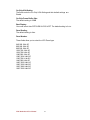
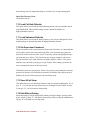
7.8
PnP / PCI Configuration
This option configures the P CI bus system. All PCI bus systems on the system
use INT#, thus all installed PCI cards must be set to this value.
Phoenix - AwardBIOS CMOS Setup Utility
Pnp/PCI Configurations
Reset Configuration Data
[Disable]
Resources Controlled By
IRQ Resources
PCI/VGA Palette Snoop
[AUTO]
[Press Enter]
[Disable]
Item Help
Menu Level ►
↑↓→←:Move Enter:Select +/-/PU/PD:Value F10:Save Esc:Exit F1:Genenal
Help
F5: Previous Values
F6: Fail -Safe Defaults F7: Optimized Defaults
Reset Configuration Data
This field allows you to determine whether to reset the configuration data or not. The
default value is Disabled.
Resources Controlled by
This PnP BIOS can configure all of the boot and compat ible devices automatically
with the use of a use a PnP operating system such as Windows 95.
PCI/VGA Palette Snoop
Some non-standard VGA display cards may not show colors properly. This field
allows you to set whether or not MPEG ISA/VESA VGA cards can wo rk with
PCI/VGA. When this field is enabled, a PCI/VGA can work with an MPEG
ISA/VESA VGA card. When this field is disabled, a PCI/VGA cannot work with an
MPEG ISA/VESA card.
I530 Motherboard User Manual
50
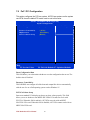
7.9 PC Health Status
This section shows the parameters in determining the PC He alth Status. These
parameters include temperatures, fan speeds and voltages.
CPU Warning Temperature
This field allows the user to set the temperature so that when the temperature is
reached, the system sounds a warning. Thi s function can help prevent damage to the
system that is caused by overheating.
Temperatures/Voltages
These fields are the parameters of the hardware monitoring function feature of the
motherboard. The values are read -only values as monitored by the syst em and show
the PC health status.
Shutdown Temperature
This field allows the user to set the temperature by which the system automatically
shuts down once the threshold temperature is reached. This function can help prevent
damage to the system that is c aused by overheating.
Smart Fan2 Temperature
This field enables or disables the smart fan feature. At a certain temperature, the fan
I530 Motherboard User Manual
51
starts turning. Once the temperature drops to a certain level, it stops turning again.
Smart Fan Tolerance Value
The default value is 5.
7.10 Load Fail-Safe Defaults
This option allows you to load the troubleshooting default values permanently stored
in the BIOS ROM. These default settings are non -optimal and disable all
high-performance features.
7.11 Load Optimized Defaults
This option allows you to load the default values to your system configuration. These
default settings are optimal and enable all high performance features.
7.12 Set Supervisor Password
These two options set the system password. Supervisor Password s ets a password that
will be used to protect the system and Setup utility. User Password sets a password
that will be used exclusively on the system. To specify a password, highlight the type
you want and press <Enter>. The Enter Password: message prompts o n the screen.
Type the password, up to eight characters in length, and press <Enter>. The system
confirms your password by asking you to type it again. After setting a password, the
screen automatically returns to the main screen.
To disable a password, just press the <Enter> key when you are prompted to enter the
password. A message will confirm the password to be disabled. Once the password is
disabled, the system will boot and you can enter Setup freely.
7.13 Save & Exit Setup
This option allows you to determine whether or not to accept the modifications. If you
type “Y”, you will quit the setup utility and save all changes into the CMOS memory.
If you type “N”, you will return to Setup utility.
7.14 Exit Without Saving
Select this option to exit the Setup utility without saving the changes you have made
in this session. Typing “Y” will quit the Setup utility without saving the modifications.
Typing “N” will return you to Se tup utility.
I530 Motherboard User Manual
52
Note: Digital I/O Sample Code
//File of the Main.cpp
//===================================== ======================
//This code is for test I530 Super I/O.
//===================================== ======================
#include <dos.h>
#include <conio.h>
#include <stdio.h>
#include <stdlib.h>
//========================== ==================================
#define W83627EHG_INDEX_PORT 0x2E
#define W83627EHG_DATA_PORT 0x2F
//===================================== =======================
#define W83627EHG_REG_LD 0x07
//===================================== =======================
#define W83627EHG_UNLOCK 0x87
#define W83627EHG_LOCK 0xAA
//===================================== =======================
void ClrKbBuf(void);
void Unlock_W83627EHG(void);
void Lock_W83627EHG(void);
void Set_W83627EHG_Reg(unsigned char,unsigned char);
unsigned char Get_W83627EHG_Reg(unsigned char);
int main ();
//===================================== =======================
int main ()
{
unsigned char ucDO = 0; //data for digital output
unsigned char ucDI; //data for digital input
unsigned char ucBuf;
Set_W83627EHG_Reg(0x07,0x07);//switch to logic device 7
//
//
PIN 121~128 function select
Bit0 = 0 -> Game Port.
I530 Motherboard User Manual
53
//
= 1 -> GPIO1.
ucBuf = Get_W83627EHG_Reg(0x29);
Set_W83627EHG_Reg(0x29,ucBuf|0x01);
// Bit0 = 0 -> GPIO1 is inactive.
// Bit1 = 1 -> Activate GPIO1.
ucBuf = Get_W83627EHG_Reg(0x30);
Set_W83627EHG_Reg(0x30,ucBuf|0x01);//Activate GPIO1
Set_W83627EHG_Reg(0xF0,0x0F);//switch GPIO Input(1)/Output(0) port
Set_W83627EHG_Reg(0xF1, 0x00); //clear
ucDI = Get_W83627EHG_Reg(0xF1) & 0x 0F;
ClrKbBuf();
while(1)
{
ucDO++;
Set_W83627EHG_Reg(0xF1, ((ucDO & 0x0F) << 4));
ucBuf = Get_W83627EHG_Reg(0xF1) & 0x0F;
if (ucBuf != ucDI)
{
ucDI = ucBuf;
printf("Digital I/O Input Changed. Current Data is 0x%X \n",ucDI);
}
if (kbhit())
{
getch();
break;
}
delay(500);
}
return 0;
}
//===================================== =======================
void ClrKbBuf(void)
{
while(kbhit())
{ getch(); }
I530 Motherboard User Manual
54
}
//------------------------------------------------------------------------ --void Unlock_W83627EHG (void)
{
outportb(W83627EHG_INDEX_PORT, W83627EHG_UNLOCK);
outportb(W83627EHG_INDEX_PORT, W83627EHG_UNLOCK);
}
//===================================== =======================
void Lock_W83627EHG (void)
{
outportb(W83627EHG_INDE X_PORT, W83627EHG_LOCK);
}
//===================================== =======================
void Set_W83627EHG_Reg( unsigned char REG, unsigned char DATA)
{
Unlock_W83627EHG();
outportb(W83627EHG_INDEX_PORT, REG);
outportb(W83627EHG_DATA_PORT, DATA);
Lock_W83627EHG();
}
//===================================== =======================
unsigned char Get_W83627EHG_Reg( unsigned char REG)
{
unsigned char Result;
Unlock_W83627EHG();
outportb(W83627EHG_INDEX_PORT, REG);
Result = inportb(W83627EH G_DATA_PORT);
Lock_W83627EHG();
return Result;
}
//===================================== =======================
I530 Motherboard User Manual
55