1
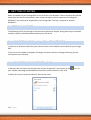
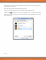
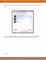
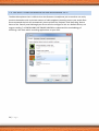
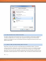
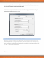
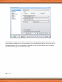
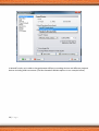
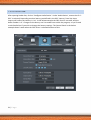
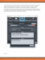
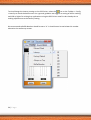
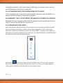
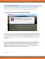
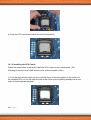
User Manual V1.2
1|Page
TABLE OF CONTENTS
1. ABOUT YOUR OPC
2. ABOUT THIS MANUAL
3. IN THE BOX
4. TOP PANEL AND REAR PANEL
5. GETTING STARTED
5.1 GETTING CONNNECTED
5.1.1 Connecting using a LAN (Local Area Network)
5.1.2 Connecting using Wireless (Wi-Fi)
5.2 REGISTRATION + SOFTWARE ACTIVATION
5.2.1 AmpliTube
5.2.2 EZ Drummer Lite/Toontrack solo
5.2.3 Mixcraft
5.2.4 Studio One
6 SET-UPS
6.1 RECORDING USING THE TOP PANEL ¼” INPUTS + BUILT-IN SPEAKERS
6.1.1 Guitar and Bass
6.1.2 Vocals
6.2 USB MICROPHONES
6.3 POWERED ANALOG AUDIO MONITORS
6.4 POWERED DIGITAL AUDIO MONITORS
7. DEVICES + DRIVERS
7.1 ACCESSING AND CONFIGURING THE OPC AUDIO DRIVER
7.2 CHANGING THE INPUT AND OUTPUT LEVELS FOR OPC DRIVER
7.3 CHANGING DEFAULT PLAYBACK DEVICE
7.4 CONFIGURING SOFTWARE DRIVERS
2|Page
7.4.1 AmpliTube
7.4.2 EZ Drummer Lite/Toontrack solo
7.4.3 Mixcraft
7.4.4 StudioOne
8. COMPUTER RECORDING FUNDAMENTALS
9. TROUBLE SHOOTING
9.1 INTERNET CONNECTIVITY
9.1.1 I can‟t access the internet
9.1.2 My wireless network won‟t accept my password
9.2 HARDWARE + OS
9.2.1 I have an Issue with my computer
9.2.2 I can‟t get a wireless signal
9.2.3 At random points the screen shows static noise
9.2.4 Windows 7 says I‟ve exceeded the amount of power on a USB bus
9.2.5 Speaker related issues
9.3 SOFTWARE + DRIVERS
9.3.1 Cannot find your audio device error message
9.3.2. Studio One VST Plug-in authorisations
9.3.3. Occasional low latency audio artifacts
9.3.4 OPC Driver is not visible in the Windows Taskbar
9.5 WHERE WE CAN HELP
9.5.1 Software providers
9.5.2 Microsoft Windows OS
9.5.3 Orange
10. AUTHORISED UPGRADES
10.1 UPGRADING THE CPU
3|Page
10.2 UPGRADING RAM
10.3 INSTALLING AN EXPANSION CARD
10.3.1 Installing and removing a PCI Express graphics card
11. SAFE OPERATION
12. CARING FOR YOUR OPC
13. WARRANTIES AND EXCLUSIONS
4|Page
1. ABOUT YOUR ORANGE OPC
Your Orange OPC is a state-of-the-art desktop computer, designed to be a plug and play solution for
creating and recording your music right out of the box.
[NOTE] Although your Orange OPC comes pre-installed with Windows 7 and Windows Security
Essentials, you will need to register all music software prior to first use. Please see 5.2
REGISTRATION + SOFTWARE ACTIVATION for more information.
2. ABOUT THIS MANUAL
This manual was written to ensure you get the most out of your Orange OPC experience. Once you
have registered the pre-installed recording software, we strongly encourage you to read 6. DEVICES
+ DRIVERS and 7. COMPUTER RECORDING FUNDAMENTALS. These sections reflect the “best
practices” developed by the Orange OPC team.
3. IN THE BOX
Your Orange OPC box should contain the following items:
• Orange OPC
• Power cable
• Keyboard
• Mouse
• Quick start guide
• Activation sheet
If any of these items are missing, please contact support, after registering your Orange OPC:
Registration URL: http://www.OrangeOPC.com/register
Support URL: http://www.OrangeOPC.com/support
5|Page
4. TOP PANEL + REAR PANEL
The architecture on your OPC was designed with connectivity and portability in mind, allowing you
to configure your recording set-up in a variety of ways. For more information, please refer to 6.
SET-UPS.
TOP PANEL
(1) Input 1: 1/4" instrument Input
(2) Input 2: 1/4" instrument, keyboard, or microphone Input
(3) +20dB Boost Switch: Toggles 20dB Boost function on Input 2
(4) Instrument/Microphone Switch: Toggles between Instrument and Mic levels on Input 2
(5) Volume: Adjusts the volume EQ of the OPC speakers
(6) Treble: Adjusts the treble EQ of the OPC speakers
(7) Middle: Adjusts the middle EQ of the OPC speakers
(8) Bass: Adjusts the bass EQ of the OPC speakers
(9) Power Light: Indicates if Windows is on. It is off when Windows is in sleep/shut down.
(10) Power Button/HD activity light: Press briefly to turn the OPC on and off. The orange
ring around the button flashes when the internal Hard Drive is being accessed
(11) USB 2.0: Top Panel USB port for USB devices and peripherals
(12) DVD Drive: Slide in your DVD with the label side facing the back of the OPC
(12) DVD Drive Eject Button: Press to eject the media in the DVD drive
6|Page
BACK PANEL
(1) Optical S/PDIF Out Connector: This connector sends digital audio to external systems
supporting TosLink terminated S/PDIF cables.
[WARNING!] Always minimise the volume on the Digital Audio ‘Levels’ Panel prior to selecting this
output. Please see 7. DRIVERS + DEVICES for more information.
7|Page
(2) Coaxial S/PDIF Out Connector: This connector sends digital audio to external systems
supporting coaxial S/PDIF cables.
[WARNING!+ Always minimise the volume on the Digital Audio ‘Levels’ Panel prior to selecting this
output. Please see 7. DRIVERS + DEVICES for more information.
(3) D-Sub Monitor Port: The D-Sub port supports a 15-pin D-Sub terminated monitor cable.
(4) HDMI Port: The HDMI (High-Definition Multimedia Interface) port provides an all-digital
audio/video interface to transmit uncompressed audio/video signals and is HDCP compliant.
Connect HDMI audio/video devices to this port. HDMI supports a maximum resolution of
1920x1200 with the actual resolution being dependent on the monitor being used.
*NOTE+ Unless you desire to use your HDMI device for audio playback, once you’ve installed an
HDMI device make sure the default playback device for audio remains set to the Orange OPC’s
internal speakers. Selecting an HDMI device for audio playback will automatically bypass your
Orange OPC’s internal speakers. Please see 7. DRIVERS + DEVICES for directions on selecting your
default playback device.
[NOTE] The HDMI audio output only support AC3, DTS, and 2-channel-LPCM formats. AC3 and DTS
also require the use of an external decoder on your HDMI connected device.
*NOTE+ While the Orange OPC’s motherboard provides three video output ports (D-Sub and
2xHDMI) , some dual monitor configurations are only supported in the operating system
environment only, not during the BIOS Setup or POST process.
(5) USB 2.0 Ports: These ports support the USB 2.0 compliant devices such as a keyboard, mouse,
printer, flash drive, or hard drive, and are also reverse compatible to the USB 1.1 standard.
8|Page
(6) eSATA 3Gb/s Port: The eSATA 3Gb/s port conforms to SATA 3Gb/s standard and is compatible
with SATA 1.5Gb/s standard. Use this port to connect an external SATA device.
(7) RJ-45 LAN Port: The Gigabit Ethernet LAN port provides Internet connection at up to 1 Gbps
data rate. The following describes the states of the LAN port LEDs.
(8) USB 3.0 Ports: These ports support USB 3.0 compliant devices such as a keyboard, mouse,
printer, flash drive, or hard drive, and are reverse compatible to the USB 2.0 specificiation.
(9) Intergrated Audio Jacks: These jacks are for the ‘High Definition Audio’ audio driver included
with the OPC.
(a) Centre/Subwoofer Speaker Out Jack (Orange): Use this audio jack to connect center/subwoofer
speakers for use in a 5.1 or 7.1-channel audio configuration.
[NOTE] To utilise this output you must:
1) Connect the cable
2) Select external speakers 3.5 mm Jack in the Sound > Playback Panel as the default playback
device. Please see 7.2 CHANGING DEFAULT PLAYBACK DEVICE.
(b) Rear Speakers Output Jack (Black): Use this audio jack to connect rear speakers for use in a 5.1
or 7.1-channel audio configuration.
[NOTE] To utilise this output you must:
9|Page
1) Connect the cable
2) Select External Speakers 3.5 mm Jack in the Sound > Playback Panel as the default playback
device. Please see 7.2 CHANGING DEFAULT PLAYBACK DEVICE.
(c) Side Speakers Output Jack (Gray): Use this audio jack to connect side speakers for use in a 7.1channel audio configuration.
[NOTE] To utilise this output you must:
1) Connect the cable
2) Select External Speakers 3.5 mm Jack in the Sound > Playback Panel as the default playback
device. Please see 7.2 CHANGING DEFAULT PLAYBACK DEVICE.
(d) Line In Jack (Blue): Use this audio jack for line in devices such as an MP3 player.
(e) Front Speakers Line Out Jack (Green)
Use this audio jack to connect front speakers in a 5.1/7.1-channel audio configuration. You can also
use this 3.5mm “mini” output jack for headphones or 2-channel speaker.
[NOTE] To utilise this output you must:
1) Connect the cable
2) Select External Speakers 3.5 mm Jack in the Sound > Playback Panel as the default playback
device. Please see 7.2 CHANGING DEFAULT PLAYBACK DEVICE.
(f) Mic In Jack (Pink)
The default mic in jack. 3.5mm input for general purpose (non-musical) microphone functions like
chat.
10 | P a g e
(10) Bracket Screws: These screws hold the PCI-E bracket in place. When adding a device into this
port (such as a Graphics card) use the bracket lock on the other side to lock the device in place.
(11) Line In L/R: 1/4" Left/Right Line Inputs, bypasses Windows
(12) Line Out L/R: 1/4" Left/Right Line Outputs, use right output for stereo headphones
(13) Rear Exhaust Fan: This low powered fan constantly spins to help cool the OPC
(14) Fuse: This is the fuse for the internal amplifier inside the OPC
(15) AC In: This is the socket for your power cord
(16) Power Switch: Controls power to the OPC- including the amplifier and computer parts
11 | P a g e
5. GETTING STARTED
When you power up your Orange OPC for the first time, the Windows 7 Home Premium Out Of Box
Experience will launch automatically. Basic setup information will be requested, including the
Windows 7 licence key that shipped with your Orange OPC. This key is required to activate
Windows 7.
5.1 GETTING CONNECTED
The following tips for connecting to the Internet should prove helpful, noting that the pre-installed
software requires web-based authorisation prior to first use.
5.1.1 CONNECTING USING A LAN (LOCAL AREA NETWORK)
1) Connect an Ethernet cable from your Internet router to the LAN Port on the back of your Orange
OPC.
2) An icon on the Taskbar will appear showing a computer monitor and plug confirming you are
connected to your network.
5.1.2 CONNECTING USING WIRELESS (WI-FI)
1) Raise the Wi-Fi Antenna on the Top Panel of your Orange OPC. You should see this
your Taskbar indicating that Windows has found a wireless network in your area.
2) Select this icon to reveal the Wireless Connection panel
.
12 | P a g e
icon on
3) Select your wireless network from the list of networks displayed.
4) Click the Connect button to join your network.
5) If your network requires a password, you will be prompted to enter it.
6) Once you've entered the password click OK to connect to the Internet.
7) The number of bars illuminated in this
this case is strong.
13 | P a g e
icon reveal the strength of your connection, which in
5.2 REGISTRATION + SOFTWARE ACTIVATION
Your Orange OPC comes pre-installed with full-version premium software, which must be activated
prior to first use. Each of our software partners have developed unique authorisation procedures to
combat software piracy. Whilst separate authorisation processes are not convenient, they do
enable us to offer the best possible software combinations for you, the end user. We believe you’ll
find the trade-off well worth it.
Registration for each program is only required once and has the added benefit of enabling software
vendors to supply you with valuable technical support, as well as program updates. Software
registration involves either: 1) creating an online account with the respective software provider and
activating the software using your that account or 2) simply inputting an activation code into the
requested authorisation wizard inside the program.
[NOTE] If you have lost any of your authorisation codes, please visit:
http://www.OrangeOPC.com/support
5.2.1 IK MULTIMEDIA AMPLITUBE
Amplitube 3 must be registered and authorised, to enable permanent unrestricted functionality, as
well as access to the user area. The activation process is simple and instructions are provided in the
‘Product Authorization’ wizard. This wizard launches automatically when an unregistered copy of
Amplitube is opened. It can also be manually opened by selecting: Start > All Programs > IK
Multimedia > right clicking ‘Authorization Manager’ > selecting ‘Run as Administrator’ from the
‘Open’ menu.
For more information about authorising Amplitube 3, please read the ‘Installation and
Authorization Manual’ which can be located by selecting: Start > All Programs > IK Multimedia >
‘Authorization Manager’ folder > Installation and Authorization Manual.
5.2.2 TOONTRACK SOLO/EZ DRUMMER LITE
A Toontrack user account is required to activate the Toontrack Solo standalone application and EZ
Drummer Lite plug-in. Simply follow the instructions in the authorisation screen presented upon
first launch of EZdrummer Lite. We recommend opening Toontrack solo to facilitate the
authorisation process.
14 | P a g e
On first launching EZdrummer you will be presented with the authorisation screen. Follow the
instructions and, if this is your first Toontrack product, create a new user account at
http://www.toontrack.com.
1) After creating a user account, login to your account at http://www.toontrack.com and select ‘My
Products’ then select ‘Register New Product’.
2) Type in your serial number for EZ Drummer Lite
3) Click on Authorize Product
4) Key in the Computer ID exactly as shown in the the Ezdrummer interface.
5) Generate the Authorization Code online by clicking on ‘Authorize’.Type in or paste the code into
EZdrummer lite..
3) You will be greeted with a congratulation message once EZ Drummer has been authorised
sucessfully.
Please contact [email protected] with your Computer ID and serial number if the
authorisation process fails for whatever reason.
5.2.3 ACOUSTICA MIXCRAFT
To register Mixcraft:
1) Open the application by selecting the Mixcraft icon from within the Start Menu.
2) Select ‘Enter Registration Code’ from the Help Menu within Mixcraft.
3) Type in your Registration ID and Registration code found on your OPC activation sheet.
4) Select ‘Register’.
5.2.4 PRESONUS STUDIO ONE
Studio One must first be registered prior to completing the activation process.
I. Register Studio One:
1) Launch the program and the ‘Activate Studio One’ Menu will appear.
15 | P a g e
2) New Studio One users will need to create a user account. Select the ‘Create Account’ link if your
computer is connected to the Internet. If your computer is not connected to the Internet, go to a
computer that is connected and visit this URL: http://www.presonus.com/registration.
3) Once at the registration page, select the ‘Register’ link, fill out the form, then select ‘Submit’.
4) PreSonus will email a verification code to the supplied email address.
II. Activate Studio One
1) Now you have your own user account, launch Studio One and the activation menu will
automatically appear.
2a) Online Activation
Ensure your OPC is connected to the internet and click the Activate Online link. The registered
username, password and product key will be required. Click on the Activate button to finish the
activation process.
2b) Offline Activation
If your OPC is not connected to the internet, click the Activate Offline link in the Activate Studio
One menu, and make a note of the Activation Code shown under step 3 in the instructions.
3) From an internet enabled device log in to the PreSonus user area by visiting:
http://www.presonus.com/registration.
4) Select Software Registration and enter the provided Product Key. A page should be displayed
which now displays the Studio One product.
5) Clicking the Activate link next to the product will provide an Activation Code which should be
entered into the Studio One program.
16 | P a g e
6. SET-UPS
In 4. IN + OUTS we detailed the massive range of connection options you have with the
OPC. In this section we're going to address how to get the most out of your OPC using a
number of these options.
6.1 RECORDING USING THE TOP PANEL ¼” INPUTS + BUILT-IN SPEAKERS
The ¼” inputs on the Top Panel of your OPC offer a number of straight forward configuration and
set-up options.
6.1.1 GUITAR + BASS
If you're only going to be recording guitar and bass, we'd suggest using Input 1 for guitars and Input
2 for bass, making sure the Instrument/Microphone Switch is set to Instrument. Multiinstrumentalists in particular benefit from having their choice of instruments wired and ready to go
at all times. Simply select the appropriate INPUT in the application you're woking in.
6.1.2 VOCALS
To record vocals insert a 1/4" terminated microphone cable into Input 2, activate the Boost switch,
and select the Microphone position of the Instrument/Microphone Switch. When tracking vocals
we'd monitoring with headphones and turning OPC's Volume Control to 0 to avoid track bleed and
feedback.
*NOTE+ Input 1 & 2 are part of the OPC’s audio interface and you must first have one of the
recording applications open before you can monitor these inputs via the OPC's Internal Speakers.
Conversely the Line In L/R Jacks on the back of your OPC bypass the Audio Interface and will not
pass audio to any of the applications. These inputs are extremely useful for running instruments,
multi-effects units, or audio player (with appropriate adapters) through the OPC’s self-powered
Internal Speakers without having to first boot Windows.
6.2 USB MICROPHONES
Insert your USB terminated microphone into the USB input on the Top Panel of your OPC. Some
USB microphones like Blue Microphones Yeti have an on-board headphone output, which is
extremely convenient when tracking vocals. Please see 7. DRIVERS + DEVICES for more information.
17 | P a g e
6.3 POWERED ANALOG AUDIO MONITORS
The internal JBL speakers were designed to deliver high fidelity audio anywhere you take your OPC.
The L/R Line Out Jacks were designed to give you the option of easily connecting powered
monitors. Be sure to use high quality "balanced" TRS 1/4" terminated cables for best results. Simply
connecting your monitors to the L/R Line Out Jacks does not bypass the OPC’s Internal Speakers. To
attenuate the L/R Line Out Jacks select the
‘Volume’ Icon in Taskbar to reveal the ‘Mixer’
Panel.To attenuate the OPC’s Internal Speakers use the Volume Control located on the Top Panel.
6.4 POWERED DIGITAL AUDIO MONITORS
Your OPC supports digital monitors via the S/PDIF outputs on the Back Panel of your OPC. Since the
S/PDIF output bypasses the OPC's VOLUME CONTROL, volume adjustments must be made from
within Windows. Please see 7.3 CHANGING DEFAULT PLAYBACK DEVICES for configuration
instructions and 9.2.5 SPEAKER RELATED ISSUES for tips on how to use the Windows Volume Mixer.
18 | P a g e
7. DEVICES + DRIVERS
Your OPC features a massive range of I/O options. Windows routes Devices using Drivers, much like
you would use a patch bay to route signal in a traditional studio. The Top Panel Inputs and Internal
Speakers are referred to as Devices. The OPC Driver enables recording programs to receive signal
from Input Devices and in turn route those sounds to Output Devices. Your OPC ships with the Top
Panel Inputs, OPC Driver, and Internal Speakers set as your Default Devices and Drivers. Once
you’ve authorised the pre-installed software you will be ready to start tracking!
Understanding how to manage Driver Latency is key to getting the most out of your OPC. Orange
has developed a proprietary Driver for the OPC that allows you to get much lower Latency that the
stock Windows Audio Driver. Please see 8. COMPUTER RECORDING BASICS for strategies on how to
get the best performance out of your OPC Driver.
[NOTE] When selected, the OPC Driver sets global input and ouput levels. This section will cover
that functionality as well as a number of other key Device + Driver configurations and protocols.
[NOTE] When the OPC Audio Driver is selected as the Default Device all audio will be pushed
through the OPC Audio Driver by default. The OPC Audio Driver routes sound to the Internal
Speakers and the Line Out L/R Jacks on the Back Panel of your OPC.
7.1 ACCESSING AND CONFIGURING THE OPC AUDIO DRIVER
You can access the OPC Driver by either:
1) Selecting the orange coloured ‘O’ logo on the right of the Windows Taskbar.
2) Selecting the white arrow if it is hidden from the Taskbar.
19 | P a g e
7.2 CHANGING THE INPUT AND OUTPUT LEVELS FOR OPC DRIVER
Opening the panel allows you to mute, change volume of left and speakers and input devices on
the top OPC panel. ‘1’ and ‘2’ refer to Input 1 and 2 on the top of the OPC. We recommend keeping
these settings on 0dB.
7.3 CHANGING DEFAULT PLAYBACK DEVICE
20 | P a g e
The following example demonstrates how to switch between the OPC’s Internal Speakers and the
External Speakers 3.5 mm Jack.
[NOTE] The icons/description may differ slightly on your OPC:
1) Connect one or more Devices to the 3.5mm Jack on the Back Panel of your OPC
2) Right click the
Volume Icon in Taskbar > select ‘Playback Devices’ to launch the ‘Sound’ Panel
pictured below. The green circle with the check mark indicates that the OPC Speakers are selected
as the Default Device..
21 | P a g e
3) Select the ‘External Speakers 3.5 mm Jack’ icon to activate the ‘Set Default’ button.
22 | P a g e
4) Select the ‘Set Defaul’t button to switch the Default Playback Device to External Speakers 3.5 mm
Jack.
[NOTE] This is the same procedure you would follow to select other Default Playback Devices. The
same logic also applies to selecting Recording Devices via the ‘Recording’ Tab shown above.
23 | P a g e
7.4 THE SELF-CONFIGURING BLUE MICROPHONES YETI
The Blue Microphones Yeti is USB mic that also features a headphone jack so vocalists can easily
monitor themselves with a minimal amount of cable spaghetti streaming across your studio floor.
Once connected the Yeti will automatically show up both the ‘Playback’ and ‘Recording’ Device
Panes of the ‘Sound’ panel.Although you do not need to configure a Yeti as a Default Device, we
suggest reading 7.4 CONFIGURING SOFTWARE DRIVERS to understand the methodology of
accessing a Yeti from within recording applications on your OPC.
24 | P a g e
7.4 CONFIGURING SOFTWARE DRIVERS
Your OPC is configured out of the box but over time you may decide to install program updates or
use different audio devices for recording. Here’s a guide for checking that each of the bundles
programs are configured to their correct defaults and how to change them should you wish to use a
different audio device.
7.4.1 AMPLITUBE (STAND-ALONE AND PLUG-IN)
AmpliTube 3 comes with your OPC as a VST/RTAS plugin and standalone program. The device
settings of AmpliTube is dependant on Mixcraft and Studio One, however as a standalone program
the AmpliTube uses its own device settings. To access the device settings click on Settings>Audio
MIDI Setup. This will bring up the Hardware Settings page. Check the the ASIO is selected in the top
drop down list and the Input device is set to ‘ASIO 2.0 - OPC’. The buffer size reflects the OPC panel.
25 | P a g e
You can’t change the buffer size when AmpliTube is open and so the ‘Panel’ button doesn’t work
from within the Hardware Settings page of AmpliTube 3.
AmpliTube has the option of ‘DirectX’ as an input driver. We strongly recommend not using this
because of the high latencies with this driver.
7.4.2 EZ DRUMMER LITE/TOONTRACK SOLO
EZ Drummer comes pre-installed on your OPC as a VST plug-in and as part of the Toontrack Solo
standalone application. To change the Device Driver from within Toontrack Solo: select Options >
Audio> Audio Device. By default Device Type should be set to ‘ASIO’ and the Output Driver to ‘ASIO
2.0 - OPC’ as shown in the example below.
26 | P a g e
7.4.3 MIXCRAFT
After opening Mixcraft and your’e in a project: select File > Preferences. Here you’re able to select
between driver modes. By default the Driver should be ASIO and the Default Recording Device
should be ‘OPC 1/2:L OPC1/2:R’. The Playback Device should be set to the same device.
Note that when using the ASIO you’re limited to only using the top panel guitar/mic jacks and the
rear 1/4” ports. This is the nature of the low latency ASIO technology used. If you plug in a USB
device for recording, you’ll need to switch over to the WaveRT driver or use that devices ASIO
driver if available.
27 | P a g e
WaveRT allows for low latencies with the freedom of choosing multiple outputs and various inputs
across different USB devices. In the below image, we’ve changed to WaveRT so we can now see our
USB Microphone in the list. A low latency is achieved by using ‘Exclusive Mode’ which cuts audio
from outside the program while Mixcraft is open.
28 | P a g e
In WaveRT mode, we’re able to change between different recording devices and different playback
devices including USB instruments (The Blue Snowball USB Microphone in our example below).
29 | P a g e
Mixcraft translates the top two inputs on the OPC as Left Channel and Right Channel. Select ‘Left
Channel’ if your guitar is plugged into ‘Input 1’ and select ‘Right Channel’ if your guitar/instrument
is plugged into input 2.
Check ‘Monitor Incoming Audio’ to hear the audio back through speakers/headphones while
playing.
30 | P a g e
7.4.4 STUDIO ONE
After opening Studio One, click on ‘Configure Audio Device’. Under ‘Audio Device’, ensure that ‘2.0 OPC’ is selected. Depending on what latency you defined in the OPC ‘Latency’ Panel the input
Latency will reflect the Latency in ‘ms’. In the below example the OPC Panel is set to 48, and the
buffer number is ‘4’. Changes to the latency can’t be made from within the program, so you’ll need
to exit Studio One if you wish to change the latency settings. The Control Panel in the below
example doesn’t work when the OPC driver is selected because of this.
31 | P a g e
If you want to make use of other USB devices and output to different sources you’ll need to make
use of the Windows audio within Studio One. In the below example we’ve selected ‘Windows
Audio’ as our main OPC driver and clicked on ‘Control Panel’ to select our ‘Playback’ and
‘Recordnig’ device. We’ve taken the latency down to 10 ms and kept exclusive mode turned off for
lower latency. Studio One accesses the Windows Audio driver a little differently to Mixcraft which is
why we can’t get as low latencies in Studio One as in Mixcraft.
32 | P a g e
8. COMPUTER RECORDING BASICS
Even on the largest recording systems, as the track count grows the CPU becomes increasingly
taxed. This is especially the case if you are using numerous “instances” of plug-ins. Every time you
load a plug-in on a track whether you are using another instance of that plug-in on another track
already, you are adding to the load on your CPU. The following are a number of “best practices”
that will help you conserve CPU for when you will need it the most - tracking your final overdubs
and during the mix process.
8.1 MIXING AS YOU TRACK
A number of engineers are in the practice of crafting mixes as they track. This involves strategic use
of resources in combination with a well organised approach to what gets tracked and when. This
can vary depending on the song or artist, but using this tried and true approach will allow you to
get the most out of your OPC.
8.2 RESOURCES AND RECORDING
If possible, record as many of your live tracks as early in the song development process as is
possible. By separating your production process into tracking and mixing phases you will be able to
get the most out of your resources.
8.3 LATENCY
As the name implies, Latency refers to a measurement of time. In the world of recording this is
traditionally the delay between when you play something and how long it takes for the computer to
play it back. The OPC DRIVER is capable of delivering an extremely low 48 samples of latency, which
is ideal for tracking. However, low latency also means your computer is working much harder, so as
you move from tracking to mixing, we'd suggest moving to a higher setting.
33 | P a g e
To view/change the Latency setting on the OPC Driver: select the
icon on the Taskbar > Config
> Latency to reveal the below menu. As a general guideline we suggest as setting of 48 for tracking
and 128 or higher for mixing Any applications using the OPC Driver must first be closed prior to
making adjustments to the Latency setting.
We recommend to BufferNumber should be set to ‘4’. It should never be set below this number
otherwise the audio may stutter.
34 | P a g e
8.4 PLUG-INS
Amplitube and EZ Drummer are available both as stand alone applications and as plug-ins on your
OPC. Each time you create a new guitar track using Amplitube as a plug-in, you are creating another
instance of that plug-in. Even the best plug-ins can become resource hogs as your track counts
grow, and increasing latency only goes so far once your session gets really bloated. As you make
changes to a preset it is always a good idea to save them so your OPC has one less task to manage.
8.5 TRACK BOUNCES
Another great workaround when you're running out of resources is to "bounce" the output of a
resource heavy track to second track and then take the initial track offline. You can always bring the
first track back online if you need to make any changes. This is especially useful in case you need to
add overdubs close to the mixing phase and you've got a lot of tracks. If you're really running out of
resources but need to squeeze in a few more overdubs, bounce your entire session down to two
tracks, and then take all the others offline. When your done with your overdubs, bring the latency
back up and bring the other tracks back online to mix.
35 | P a g e
9. TROUBLE SHOOTING
Countless hours of testing have given us a good sense of the most common challenges you will
encounter as an end user. If you have not already read 7. DEVICES and DRIVERS we STRONGLY
encourage you to do so prior to reading this section.
9.1 INTERNET CONNECTIVITY
We know there are few things more frustrating than being able to connect to the internet when
you want to. We found the follow addressed the issues we faced when testing the OPC.
9.1.1 I CAN’T ACCESS THE INTERNET
Right click on the network icon on the windows Taskbar and click on ‘Troubleshoot problems’.
Follow the steps and Windows will do it’s best to help you resolve the connection issue.
9.1.2 MY WIRELESS NETWORK WON’T ACCEPT MY PASSWORD
Depending on noise from other wireless devices, the signal between the OPC and the router could
be too weak to negotiate a connection. Try changing the angle of the OPC antenna to get a better
signal from your router. If possible, try changing the wireless channel of your router (check the
manual that came with your router on how to do this) to a wireless channel that isn’t shared with
as many wireless devices in your area.
9.2 HAREWARE AND OS
From time to time, you may run into issues with the hardware and operating system. Fortunately
Windows does have tools to help fix some of these issues that may arise. One of these tools is
called ‘System Restore’ which can be found by selecting the Start menu and searching for ‘System
Restore’. The program allows you to restore Windows back to various points in time - so you can
choose a date when the OPC was setup and working fine. System Restore CANNOT be undone by
running the program again.
9.2.1 I HAVE AN ISSUE WITH MY COMPUTER
Click on the Start Menu and click on „search programs and files‟ which appears as faded
text just above the Start Menu icon. Type in „troubleshooting‟ and select the text which best
describes your problem. For example if your OPC is performing slowly, click on „Check for
performance issues‟. Follow the instructions of the wizard.
9.2.2 I CAN’T GET A WIRELESS SIGNAL
Check the wireless antenna on the Top Panel of your OPC is screwed in securely by gently
turning the antenna clock-wise. Right click on the wireless icon on the Taskbar and
36 | P a g e
„troubleshoot problems‟. If this doesn‟t help try rebooting your wireless router or moving
your OPC/wireless router closer to each other.
9.2.3 AT RANDOM POINTS THE SCREEN SHOWS STATIC NOISE
This is a hardware issue. If you have overclocked your computer, restore the BIOS to its
defaults otherwise contact us to help with the problem.
9.2.4 WINDOWS 7 SAYS I’VE EXCEEDED THE AMOUNT OF POWER ON A USB BUS
Rearrange how your connecting USB devices to spread the power across the ports more
evenly or connect the USB device to another port.
9.2.5 SPEAKER RELATED ISSUES
Most of the Speaker related issues we’ve encountered have occurred after the Default Playback
Device got changed accidentally, a cable was not properly plugged-in, or most commonly an
application’s output was accidentally muted in the ‘Volume Mixer’. The Mixer routes audio from
applications to the Default Playback Device. Please see 7.3 CHANGING DEFAULT PLAYBACK DEVICE
for information about Default Playback Devices.
Selecting the
icon on the Taskbar will reveal the Mixer Pane. The icon at the top of the
Mixer Pane displayes your Default Playback Device, which in this case is set to Digital Audio for
routing signal via the OPC’s Optical S/PDIF out to our digital monitors.
37 | P a g e
Selecting ‘Mixer’ expands the Mixer Pane. Note that the all the levels are the same except for the
Windows Media Player, which in this is set to zero and hence is delivering no ouput audio to the
Default Playback Device.
38 | P a g e
Selecting and dragging the Windows Media Player Volume Fader will now allow audio to pass to the
Default Playback Device.
In most cases you will want the Default Playback Device to be your OPC.
If you plan on using more than one set of speakers, we strongly encourage you to become familiar
with the protocol detailed in 7.3 CHANGING DEFAULT PLAYBACK DEVICE.
39 | P a g e
9.3 SOFTWARE + DRIVERS DD
Once registered, many of the Software issues you’ll encounter are Driver related. 7. DEVICES +
DRIVERS is rich with configuration tips that may solve many of your Software related issues.
9.3.1 CANNOT FIND YOUR AUDIO DEVICE ERROR MESSAGE
This is one of the most common error messages we encountered when testing the OPC. Although
we were able to open both the Mixcraft and Studio One recording applications without conflict,
that is not the case with stand-alone applications like AmpliTube and Toontrack solo. Stand-alone
applications will compete with one another as well as with recording applications for “first use” of
the OPC Driver.
If you have a number of documents and applications open and go to launch AmpliTube
there may be a delay before AmpliTube opens. In the process you may conclude that the
program did not load and try to relaunch the application. We discovered that once
AmplitTube did load a second “instance” obscured the first one in the background, again
triggering the „Cannot find Your audio device‟ error message.
40 | P a g e
9.3.2. Studio One VST Plug-in authorisations
As of time of initial release we were aware of activation issues within PreSonus Studio One
Orange Edition incorrectly identifying authorised VST plug-in as being unauthorised. A
solution to this issue is launch the application by right-clicking on the PreSonus Studio One
icon and selecting „Run as Administrator‟. If you receive a UAC prompt, select „yes‟.
9.3.3 Occasional low latency audio artifacts
You may occasionally here short chirping or buzzing noises when switching between
presets within AmpliTube or when switching plug-ins. At lower latency settings this may
occur, but these sounds should not “print” to your tracks. Try increasing the OPC Driver if
this persits as well as closing other applications running in the background.
9.3.4 OPC Driver is not visible in the Windows Taskbar
Make sure the driver isn‟t hidden by clicking the white up arrow on the right of the Windows
Taskbar. If you find it here, you can click and drag the driver icon back into the Taskbar. If
the driver can‟ be seen, reinstall the OPC driver by visiting www.OrangeOPC.com and
downloading the latest driver from there.
9.5 FACTORY RESET
Your computer has a factory reset function. Using the factory reset function restores your
OPC software and hardware to the original state in which it left us. You will lose any saved
information including programs and personal data on your OPC. Only do this if asked to by
OPC support staff or if you‟re completely confident in what you are doing.
To Reset your OPC, repeatedly press „F9‟ immediately after pressing the power button
when booting up your OPC. Select „restore image‟. Follow the on-screen instructions. The
automated process may take up to an hour - do NOT shut your computer down during this
process. Once completed, you will need your all activation serial keys to re-activate your
software.
9.6 WHO TO CONTACT
Orange is dedicated to making your OPC experience a great one. Great care has been taken to
identify and provide solutions for the most common problems we believe you’ll encounter. If there
41 | P a g e
is an issue not resolved by this manual, please contact the appropriate manufacturer per the type
of issue you are experiencing.
9.6.1 SOFTWARE PROVIDERS
Your OPC comes loaded with premium version software developed by companies with great
support portals and teams to address your software specific questions.
Product: AmpliTube
Manufacturer: IK Multimedia
Support: http://www.ikmultimedia.com/Main.html?Support.php
Product: EZ Drummer Lite
Manufacturer: Toontrack
Support: https://www.toontrack.com/support.asp
Product: Mixcraft
Manufacturer: Acoustica
Support: http://www.acoustica.com/support/index.htm
Product: Studio One Orange Edition
Manufacturer: PreSonus
Support: http://www.presonus.com/technical-support/
42 | P a g e
9.6.2 MICROSOFT WINDOWS OS
Your OPC comes loaded with Microsoft Windows 7 Home Premium. Microsoft has created an
extensive answerbase to address OS related questions at http://answers.microsoft.com/enus/windows/forum/windows_7
You will also find answers to a number of Windows related issues by
1) Selecting the Start Menu.
2) Entering “Help and Support”.
3) Typing in keywords related to your questions such as
- Connecting to the Internet
- Printing
- Changing computer settings
- Playing or creating a CD or DVD
9.6.3 ORANGE
If you are experiencing hardware related issues please contact OPC tech support:
http://www.OrangeOPC.com/support
43 | P a g e
10. UPGRADING
Performing upgrades on your OPC is very similar to those you would make on a traditional desktop
computer tower. Although you can make the following upgrades yourself, we recommend using a
certified computer technician.
10.1 UPGRADING THE CPU
Read the following guidelines before you begin to install the CPU:
1) Always turn off the computer and unplug the power cord from the power outlet before installing
the CPU to prevent hardware damage. Locate the pin one of the CPU. The CPU cannot be inserted if
oriented incorrectly. (Or you may locate the notches on both sides of the CPU and alignment keys
on the CPU socket.) Apply an even and thin layer of thermal grease on the surface of the CPU.
2) Do not turn on the computer if the CPU cooler is not installed, otherwise overheating and
damage of the CPU may occur.
10.1.1 Opening The OPC
To open the OPC unscrew the top two screws on the OPC and the bottom two screws on the OPC.
The white aluminum chassis will slide out when leaning the cabinet backwards.
10.1.2 Installing the CPU
Locate the alignment keys on the motherboard CPU socket and the notches on the CPU.
44 | P a g e
1) Gently press the CPU socket lever handle down and away from the socket with your
finger. Then completely lift the CPU socket lever and the metal load plate will be lifted as
well.
2) Hold the CPU with your thumb and index fingers. Align the CPU pin one marking
(triangle) with the pin one corner of the CPU socket (or you may align the CPU notches with
the socket alignment keys) and gently insert the CPU into position.
3) Once the CPU is properly inserted, use one hand to hold the socket lever and use the
other to lightly replace the load plate. When replacing the load plate, make sure the front
end of the load plate is under the shoulder screw.
45 | P a g e
4) Push the CPU socket lever back into its locked position.
10.1.3 Installing the CPU Cooler
Follow the steps below to correctly install the CPU cooler on the motherboard. (The
following procedure uses Intel® boxed cooler as the example cooler.)
1) If you haven't already, apply an even and thin layer of thermal grease on the surface of
the installed CPU (or you can skip this step if the cooler you‟re installing already has a new
layer of thermal grease applied).
46 | P a g e
2) Before installing the cooler, note the direction of the arrow sign on the male push pin.
(Turning the push pin along the direction of arrow is to remove the cooler, on the contrary,
is to install.)
3) Place the cooler atop the CPU, aligning the four push pins through the pin holes on the
motherboard. Push down on the push pins diagonally.
4) You should hear a "click" when pushing down each push pin. Check that the Male and
Female push pins are joined closely. (Refer to your CPU cooler installation manual for
instructions on installing the cooler.) Use extreme care when removing the CPU cooler
because the thermal grease/tape between the CPU cooler and CPU may adhere to the
CPU. Inadequately removing the CPU cooler may damage the CPU.
47 | P a g e
5) Finally, attach the power connector of the CPU cooler to the CPU fan header
(CPU_FAN) on the motherboard.
10.2 UPGRADING RAM
A DDR3 memory module has a notch, so it can only fit in one direction. Follow the steps
below to correctly install your memory modules in the memory sockets. Before installing a
memory module, make sure to turn off the computer and unplug the power cord from the
power outlet to prevent damage to the memory module. DDR3 and DDR2 DIMMs are not
compatible to each other or DDR DIMMs. Be sure to install only DDR3 DIMMs on this
motherboard.
48 | P a g e
1) Note the orientation of the memory module. Spread the retaining clips at both ends of the
memory socket. Place the memory module on the socket. As indicated in the picture on the
left, place your fingers on the top edge of the memory, push down on the memory and
insert it vertically into the memory socket.
2) The clips at both ends of the socket will snap into place when the memory module is
securely inserted.
10.3 INSTALLING AN EXPANSION CARD
Follow the steps below to correctly install your expansion card in the expansion slot.
49 | P a g e
1) Locate an expansion slot that supports your card. Remove the white metal slot cover
from the chassis back panel.
2) Align the card with the slot, and press down on the card until it is fully seated in the slot.
3) Make sure the metal contacts on the card are completely inserted into the slot.
4) Secure the card‟s metal bracket to the chassis back panel with a screw and the white
end bracket found screwed inside your OPC.
5) After installing all expansion cards, replace the chassis cover(s).
6) Turn on your computer.
7) Install the driver provided with the expansion card in your operating system.
10.3.1 Installing and Removing a PCI Express Graphics Card in PCI Express x16 Slot
1) Installing a Graphics Card:
Gently push down on the top edge of the card until it is fully inserted into the PCI Express
slot. Make sure the card is securely seated in the slot and does not rock.
50 | P a g e
2) Removing the Card:
Press the white latch at the end of the PCI Express slot to release the card and then pull
the card straight up from the slot.
51 | P a g e
11. SAFE OPERATION
We care about you and your OPC, so please abide by the following safety guidelines:
• Your OPC was created to be enjoyed in a safe environment. Listening to loud music can
and does cause permanent hearing loss - especially when using headphones.
• As your OPC powers up, it is normal to hear small “pops” though the speakers. Because
of this, please lower the Volume on the Top Panel of your OPC prior to booting.
• Remember that volume levels from different sources can vary differently so remember to
turn down the OPC volume if you were compensating for a quiet audio source. Loud noises
aren‟t just startling but can be damaging for your hearing over time.
• Only operate your OPC on a stable, flat surface away from moisture and direct sunlight.
We‟d suggest keeping a watchful eye that your OPC moving due to vibration from the
Internal Speakers or any external source.
• Do not block or obstruct the internal OPC fans. If any of the OPC fans or grilles become
blocked, the other fans may spin louder to compensate. However your OPC will turn itself
off if the computer begins to reach a high temperature.
• Keep your OPC away from liquids and wet or damp weather.
• Be sure never to block any of the ventilation holes on your OPC, ensuring you operate
your OPC in an area with adequate ventilation for the air to circulate freely.
• Over time the fan on your OPC will filter a large amount of air - and dust. It will be natural
for dust particles to accumulate on the metal grills on the side and rear of the OPC. From
time to time (after first powering down your OPC) use a dry cloth or tissue to wipe away the
dust to prevent it from entering your OPC.
• Before cleaning your OPC, make sure to first power down and then unplug your OPC from
the wall - always by gently pulling out the plug and never tugging on the cable. While we
encourage you to use gentle detergent to clean the exterior of your OPC with a soft cloth,
please be sure to apply a small amount of the cleaning solution directly to the cloth itself not your OPC.
• Always unplug your OPC from the wall prior making any modifications to internal
components.
• This product is designed for adults. Children should be supervised if allowed to hande
your OPC or cables, and should never be allowed access to the internal compartment or
components of your OPC.
52 | P a g e
• Never open any of the PSU units inside of the OPC. If you think the PSU is damaged,
contact a professional computer repair centre or Orange OPC Tech Support:
http://www.OrangeOPC.com/support.
• Under normal operating conditions, only turn your OPC off by briefly pressing the power
button on the top panel once, or by using the „Shut Down‟ command from within Windows.
Pulling the A/C cable from the wall prior to proper shut down can result in loss of data and
may compromise the stability of your OPC.
• Your OPC will still draw current to power the internal amplifier even when Windows is not
operating. To fully power down your OPC use the A/C switch located just below the A/C
connector on the back panel of your OPC.
• Always contact Orange or a certified computer repair person for servicing your OPC.
• Do not attempt to disassemble the OPC DVD drive - the laser beam used inside this drive
is harmful to human eyes and can in some cases cause permanent damage.
• Never allow the Hard Drive to come in direct physical contact with the OPC Internal
Speakers as this can cause permanent data corruption.
• Your OPC is intended for use in home or commercial environments. Do not use your OPC
in an environment where the failure of your OPC could cause harm to yourself, others, or to
the environment itself.
53 | P a g e
12. CARING FOR YOUR OPC
Although your OPC looks and sounds like an amplifier, it is in fact a PC and should be
handled as you would any other computer - with care and consideration. Please keep the
following in mind.
12.1 CLEANING
With the exception of the upgrades covered in this manual, your OPC contains no user
serviceable parts, and requires no internal maintenance. To clean the exterior surfaces of
your OPC we suggest using a light detergent and non-abrasive cloth. To ensure no liquids
or moisture enters the OPC or any of its ports when cleaning, be sure to apply cleaning
solution directly to the non-abrasive cloth and not the OPC itself. Never use solvents as
they can cause discolouration of exterior surfaces.
12.2 JACKS
Many of the jacks on your OPC are directly connected to the motherboard. It is essential
that when inserting or removing cables you do so with the utmost of care:
• When removing a cable connected to a back panel connector, first remove the cable from
your device and then remove it from the motherboard.
• When removing the cable, pull it straight out from the connector. Do not rock it side to side
to prevent an electrical short inside the cable connector.
• Always remove the cable by gently pulling on the barrel of the plug, never by the cable
itself.
54 | P a g e
13. WARRANTIES AND EXCLUSIONS*
This Orange product is protected for ONE (1) year against defects in materials and
workmanship from date of original retail purchase, provided the purchase was made from
an authorised Orange Amplifiers dealer. This warranty applies to the entire product, except
the speakers, which are protected for THREE (3) months. This warranty is void if the
equipment is inappropriately altered, misused, mishandled, suffers excessive wear, or is
serviced beyond the scope of 10. AUTHORISED UPGRADES by any parties not authorised
by Orange Amplifiers
By registering your OPC at http://www.OrangeOPC.com/warranty you will automatically
extend your warranty period (speakers excluded) to EIGHTEEN (18) months, free of
charge.
While hard drive failures are an infrequent occurrence, they can result in a loss of data. We
strongly encourage you to back up your OPC on a regular basis. Orange Amplifiers shall in
no way be responsible for loss of data.
*FOR CUSTOMERS WHO ARE COVERED BY CONSUMER PROTECTION
LAWS OR REGULATIONS IN THEIR COUNTRY OF PURCHASE, OR COUNTRY
OF RESIDENCE, THE BENEFITS CONFERRED BY THIS WARRANTY ARE IN
ADDITION TO ALL RIGHTS AND REMEDIES CONVEYED BY SUCH
CONSUMER PROTECTION LAWS AND REGULATIONS. THIS WARRANTY
DOES NOT EXCLUDE, LIMIT OR SUSPEND ANY RIGHTS OF CONSUMERS
ARISING OUT OF NON-CONFORMITY WITH A SALES CONTRACT. SOME
COUNTRIES, STATES AND PROVINCES DO NOT ALLOW THE EXCLUSION
OR LIMITATION OF INCIDENTAL OR CONSEQUENTIAL DAMAGES OR ALLOW
LIMITATIONS ON HOW LONG AN IMPLIED WARRANTY OR GIVES YOU
SPECIFIC LEGAL RIGHTS, AND YOU MAY ALSO HAVE OTHER RIGHTS THAT
VARY BY COUNTRY, STATE OR PROVINCE. THIS LIMITED WARRANTY IS
GOVERNED BY AND CONSTRUED UNDER THE LAWS OF THE COUNTRY IN
WHICH THE PRODUCT PURCHASE TOOK PLACE.
55 | P a g e