1
World-Class Mixing and Mastering Plug-Ins User Manual T-RackS CS ® T-RackS® is a registered trademark property of IK Multimedia Production. All other product names and images, trademarks and artists names are the property of their respective owners, which are in no way associated or affiliated with IK Multimedia. Product names are used solely for the purpose of identifying the specific products that were studied during IK Multimedia’s sound model development and for describing certain types of tones produced with IK Multimedia’s digital modeling technology. Use of these names does not imply any cooperation or endorsement. Fairchild® is a registered trademark property of Avid Technology, Inc. Pultec® is a registered trademark property of Pulse Techniques, LLC. LA-2A and 1176 LN are registered trademarks of Universal Audio, Inc. IK Multimedia’s products, specifically, the T-RackS Black 76 Limiting Amplifier and T-RackS White 2A Leveling Amplifier, are manufactured and developed by IK Multimedia based on its own modeling techniques. Universal Audio has neither endorsed nor sponsored IK Multimedia’s products in any manner, nor licensed any intellectual property for use in this product. Mac and the Mac logo are trademarks of Apple Computer, Inc., registered in the U.S. and other countries. Windows and the Windows logo are trademarks or registered trademarks of Microsoft Corporation in the United States and/or other countries. QuickTime and the QuickTime logo are trademarks or registered trademarks of Apple Computer, Inc., used under license therefrom. The Audio Units logo is a trademark of Apple Computer, Inc. VST is a trademark of Steinberg Media Technologies GmbH. www.t-racks.com IK Multimedia Production Srl, Via dell’Industria 46, 41122, Modena, Italy. Phone: +39-059-285496 - Fax: +39-059-2861671 IK Multimedia US LLC, 11 53 Sawgrass Corporate Pkwy. Sunrise, FL 323 Phone: (954) 846-9101 - Fax: (954) 846-9077 www.ikmultimedia.com All specifications are subject to change without further notice. 2 T-RackS CS ® Contents Contents 3 Interface 6 License Agreement 7 What’s New in T-RackS CS 10 Chapter 1 - What is T-RackS CS 1.1 - Introduction 1.2 - T-RackS CS Features 1.3 - The Custom Shop 1.3.1 - Entering the Custom Shop 1.3.2 - Gear Credits, the currency of the Custom Shop 1.3.3 - Buying Gear 1.3.4 - Trying Gear 1.3.5 - Restore Purchased Gear 1.4 - 12 processing slot mastering chain 1.5 - Accurate, complete and truly useful metering 1.6 - Plug-in and standalone version for all platforms in the same package 1.7 - High transparency, extremely high quality audio processing 1.8 - SCC™ technology 1.9 - Block diagram 1.10 - Architecture 1.11 - Interface 11 11 12 13 14 15 16 17 17 18 18 18 18 19 19 19 20 Chapter 2 - Getting started 2.1 - Using T-RackS CS as a Standalone Application 2.1.1 - Starting T-RackS CS in standalone mode 2.1.2 - Loading and playing files 2.1.3 - Inserting processors 2.1.4 - Processing your master 2.1.5 - T-RackS CS Project 2.2 - Using T-RackS as a Plug-in 21 21 21 24 25 26 27 28 Chapter 3 - General controls 3.1 - Double Chain 3.2 - Compare function 3.3 - Presets 3.3.1 - Presets backward compatibility 3.4 - A-B-C-D settings 3.5 - Preferences 3.6 - Info 3.7 - Lock 3.8 - General controls (standalone) 29 29 31 31 32 33 33 34 34 35 Chapter 4 - T-RackS CS module processors 4.1 - Vintage Tube Compressor/Limiter model 670 4.2 - Tube Program Equalizer model EQP-1A 4.3 - Opto Compressor 4.4 - Intelligent, multi-algorithm Brickwall Limiter 4.5 - High precision, high definition Linear Phase Equalizer 4.6 - Classic T-RackS Compressor 4.7 - Classic T-RackS Multi-band Limiter 4.8 - Classic T-RackS Clipper 38 39 41 43 44 46 48 50 52 Contents 3 T-RackS CS ® 4.9 - Classic T-RackS Equalizer 4.10 - Black 76 Limiting Amplifier 4.11 - White 2A Levelling Amplifier 4.12 - British Channel 4.13 - Quad Comp 4.14 - Quad Lim 4.15 - Quad Image 4.16 - De-Esser 4.17 - CSR Plate Reverb 4.17.1 - Easy 4.17.2 - I/O Levels 4.17.3 - Time 4.17.4 - Reverb 4.17.5 - Color 4.17.6 - Reflections 4.17.7 - Echo 4.17.8 - Modulation Matrix 4.17.8.1 - Modulation 4.17.8.2 - Sources (modulation sources) 4.17.8.3 - Destinations 4.17.9 - MACROS 4.17.9.1 - MATRIX 4.17.9.2 - Sources (modulation sources) 4.17.9.3 - Destinations 4.17.10 - MACRO NAME 4.18 - CSR Hall Reverb 4.18.1 - Easy 4.18.2 - I/O Levels 4.18.3 - Time 4.18.4 - Reverb 4.18.5 - Color 4.18.6 - Reflections 4.18.7 - Modulation Matrix, MARCOS and MACRO NAME 4.19 - CSR Room Reverb 4.19.1 - Easy 4.19.2 - I/O Levels 4.19.3 - Time 4.19.4 - Reverb 4.19.5 - Color 4.19.6 - Reflections 4.19.7 - Modulation Matrix, MARCOS and MACRO NAME 4.20 - CSR Inverse Reverb 4.20.1 - Easy 4.20.2 - I/O Levels (Advanced Mode) 4.20.3 - Time 4.20.4 - Reverb 4.20.5 - Color 4.20.6 - Reflections 4.20.7 - Modulation Matrix, MARCOS and MACRO NAME 53 55 57 58 61 63 65 67 68 69 69 69 70 70 70 70 71 71 72 73 74 74 74 75 76 77 78 78 78 79 79 79 79 80 81 81 81 82 82 82 82 83 84 84 84 85 85 85 85 Chapter 5 - Metering 5.1 - Peak Meter 5.2 - Perceived Loudness 5.3 - RMS 5.4 - Phase 5.5 - Correlation 86 86 87 88 88 89 Contents 4 T-RackS CS ® 5.6 - Spectrum Analyzer 89 Chapter 6 - Automation 6.1 - Automating parameters 6.2 - Left Pane 6.3 - Right Pane 91 91 91 92 Chapter 7 - Mastering tips 7.1 - Introduction 7.2 - T-RackS CS chain setup tips 7.3 - Comparing original mixes with the T-RackS processed master 7.4 - Loudness 7.5 - Simple mastering chain 7.6 - Advanced mastering chain 7.7 - T-RackS CS models tips 7.7.1 - Vintage Compressor Model 670 7.7.2 - Opto Compressor 7.7.3 - Linear Phase Equalizer 7.7.4 - Brickwall Limiter 7.7.5 - Vintage Program Equalizer EQ-1A 7.8 - Managing Latency 7.9 - Master your room 93 93 93 93 94 94 94 95 95 96 97 97 98 99 99 Chapter 8 - Troubleshooting 101 Chapter 9 - Support 9.1 - User Area 103 103 Contents 5 T-RackS CS ® Interface Preset management with GLOBAL chain and SINGLE processor presets. Complete built-in metering section with Peak, Perceived Loudness, Phase, RMS meters and Spectrum Analyzer with Peak, RMS and Averaging indication. Interface Processor module. Modular mastering/mixing chain with up to 12 parallel/series processors, one-click single/global bypass, volume-adjustable compare function. Standalone version with multiple audio file processing, waveform display, FADE IN/FADE OUT controls, LOOP auditioning, multiple SNAP points for automating audio processing points, single/ multiple file PROCESSING up to 32 bit/192 KHz WAV/AIFF files. 6 T-RackS CS ® License Agreement END-USER LICENSE AGREEMENT FOR IK MULTIMEDIA PRODUCT Please read this document carefully before breaking the seal on the media package. This agreement licenses the enclosed software to you and contains warranty and liability disclaimers. By breaking the seal on the media envelope, you are confirming to have taken notice of terms and conditions of this agreement and you acknowledge your acceptance of the software as well as your acceptance of the terms of this agreement. If you do not wish to do so, do not break the seal. Instead, promptly return the entire package, including the unopened media package, to the dealer from whom you have obtained it, for a full refund. 1) DEFINITIONS “EULA” means this end user license agreement “IK Multimedia Product” means the software program included in the enclosed package, and all related updates supplied by IK Multimedia. “IK Multimedia Product” means the software program and hardware (if any) included in the enclosed package, the related documentation, models, multimedia content (such as animation, sound and graphics) and all related updates supplied by IK Multimedia. “Not for resale (NFR) Version” means a version of IK Multimedia Product, so identified, is intended for review and evaluation purposes, only. 2) LICENSE The “IK Multimedia Product” is protected by copyright laws and international copyright treaties, as well as other intellectual property laws and treaties. The “IK Multimedia Product” is licensed, not sold. This EULA grants you the rights as specified here below. All other actions and means of usage are reserved to the written permission of the right holder IK Multimedia Production Srl: Applications Software. The “IK Multimedia Product” may be used only by you. You may install and use the “IK Multimedia Product”, or any prior version thereof for the same operating system, on up to five (5) computers, provided that (a) each computer is owned by (or leased to) and under the exclusive control of the licensee; (b) the program(s) shall NOT be used simultaneously on more than one machine, and (c) any computer(s) with IK Multimedia software installed shall not be sold, rented, leased, loaned or otherwise be removed from the licensee’s possession without first removing (uninstalling) the licensed software, except as provided in Paragraph 4 (below) pertaining to “Software Transfer”. Storage/Network use. You may also store or install a copy of the “IK Multimedia Product” on a storage device, such as a network server, used only to install or run the “IK Multimedia Product” on your other computers over an internal network; however, you must acquire and dedicate a distinct license for each user of the “IK Multimedia Product” from the storage device. Any given license for the “IK Multimedia Product” may not be shared or used concurrently or otherwise on different computers or by different developers in a given organization. 3) AUTHORIZATION The “IK Multimedia Product” only functions when you have authorized it. The “IK Multimedia Product” will be authorized upon completing the authorization procedure. Once your product is authorized, you may use it. You agree to follow the authorization procedure and will provide true, accurate and complete information about yourself. If you provide any information that is untrue, inaccurate, not correct or incomplete, or IK Multimedia has reasonable grounds to suspect that such information is untrue, inaccurate, not correct or incomplete, IK Multimedia has the right to suspend or to revoke the license. The termination of the license shall be without prejudice to any rights, whatsoever, of IK Multimedia. License Agreement 7 T-RackS CS ® 4) DESCRIPTION OF OTHER RIGHTS AND LIMITATIONS Limitations on Reverse Engineering, Decompilation, and Disassembly. You may not reverse engineer, decompile, or disassemble the “IK Multimedia Product”, except and only to the extent that such activity is expressly permitted by applicable law notwithstanding this limitation of components. The “IK Multimedia Product” is licensed as a single product. Its component parts may not be separated for use on more than one computer. Not for Resale Version. If the “IK Multimedia Product” is labeled “Not for Resale” or “NFR” or “Evaluation Copy”, then, notwithstanding other sections of this EULA, you may not sell, or otherwise transfer the “IK Multimedia Product”. Rental. You may not rent, lease, or lend the “IK Multimedia Product” to any party. Software Transfer. You may not transfer, license or sublicense your rights as Licensee of the software or any IK Multimedia product, as licensed to you under this agreement without prior written consent of the rights owner. The carrier on which the IK Multimedia product has been distributed may be transferred or otherwise made available to any third party only with the prior written consent of the rights owner and provided that (a) the original media and license(s) accompany the carrier and (b) the party transferring the media does not retain a copy of the media. 5) UPGRADES If the “IK Multimedia Product” is labeled or otherwise identified by IK Multimedia as an “upgrade”, you must be properly licensed to use a product identified by IK Multimedia as being eligible for the upgrade in order to use the “IK Multimedia Product”. An “IK Multimedia Product” labeled or otherwise identified by IK Multimedia as an upgrade replaces and/or supplements the product that formed the basis for your eligibility for such upgrade. You may use the resulting upgraded product only in accordance with the terms of this EULA. If the “IK Multimedia Product” is an upgrade of a component of a package of software programs that you licensed as a single product, the “IK Multimedia Product” may be used and transferred only as part of that single product package and may not be separated for use on more than one computer. 6) DUAL-MEDIA SOFTWARE You may receive the “IK Multimedia Product” in more than one medium. You may not loan, rent, lease, or otherwise transfer the other medium to another user, except as part of the permanent transfer (as provided above) of the “IK Multimedia Product”. 7) LIMITED WARRANTY IK Multimedia warrants to the original purchaser of the computer software product, for a period of ninety (90) days following the date of original purchase, that under normal use, the software program and the user documentation are free from defects that will materially interfere with the operation of the program as described in the enclosed user documentation. 8) WARRANTY CLAIMS To make a warranty claim under the above limited warranty, please return the product to the point of purchase, accompanied by proof of purchase, your name, your return address and a statement of the defect, or send the CD(s) to us at the below address within ninety (90) days of purchase. Include a copy of the dated purchase receipt, your name, your return address and a statement of the defect. IK Multimedia or its authorized dealer will use reasonable commercial efforts to repair or replace the product and return it to you (postage prepaid) or issue to you a credit equal to the purchase price, at its option. 9) LIMITATIONS ON WARRANTY IK Multimedia warrants only that the program will perform as described in the user documentation. No other advertising, description or representation, whether made by a IK Multimedia dealer, distributor, agent or employee, shall be binding upon IK Multimedia or shall change the terms of this warranty. License Agreement 8 T-RackS CS ® EXCEPT AS STATED ABOVE, IK MULTIMEDIA MAKES NO OTHER WARRANTY, EXPRESSED OR IMPLIED, REGARDING THIS PRODUCT. IK MULTIMEDIA DISCLAIMS ANY WARRANTY THAT THE SOFTWARE IS FIT FOR A PARTICULAR PURPOSE, AND ANY IMPLIED WARRANTY OF MERCHANTABILITY SHALL BE LIMITED TO A NINETY (90) DAY DURATION OF THIS LIMITED EXPRESS WARRANTY AND IS OTHERWISE EXPRESSLY AND SPECIFICALLY DISCLAIMED. IK MULTIMEDIA SHALL NOT BE LIABLE FOR SPECIAL, INCIDENTAL, CONSEQUENTIAL OR OTHER DAMAGES, EVEN IF IK MULTIMEDIA IS ADVISED OF OR AWARE OF THE POSSIBILITY OF SUCH DAMAGES. THIS MEANS THAT IK MULTIMEDIA PRODUCTION SRL SHALL NOT BE RESPONSIBLE OR LIABLE FOR THE LOSS OF PROFITS OR REVENUES, OR FOR DAMAGES OR COSTS AS A RESULT OF LOSS OF TIME, DATA OR USE OF THE SOFTWARE, OR FROM ANY OTHER CAUSE EXCEPT THE ACTUAL COST OF THE PRODUCT. IN NO EVENT SHALL IK MULTIMEDIA LIABILITY EXCEED THE PURCHASE PRICE OF THIS PRODUCT. 10) CHOICE OF LAW You agree that any and all claims, suits or other disputes arising from your use of the software shall be determined in accordance with the laws of Italy, in the event IK Multimedia, is made a party thereto. You agree to submit to the jurisdiction of the court in Modena, Italy for all actions, whether in contract or in tort, arising from your use or purchase of the software. 11) GENERAL This Agreement contains the complete agreement between the parties with respect to the subject matter hereof, and supersedes all prior or contemporaneous agreements or understandings, whether oral or written. All questions concerning this Agreement shall be directed to: IK Multimedia Production Srl Via dell’Industria 46 41122 Modena Italy © 2008-2012 IK Multimedia. All rights reserved. License Agreement 9 T-RackS CS ® What’s New in T-RackS CS The new T-RackS CS adds several exciting features to the already impressive power of the previous version: • Custom Shop functionality gives you the possibility to select single pieces of gear from an online shop in order to create a customized collection that will fit any personal mixing or mastering application. • ARC System 2 support lets mastering applications benefit from the 4X increased resolution of IK Multimedia’s own worldrenowned room correction package. • New selection of available modules (from the online Custom Shop) • New Gear Collections T-RackS CS comes as a free download from the IK multimedia web site upon registration of a valid account in your User Area. T-RackS CS Singles All T-RackS CS processors can be purchased as single plug-ins as modules in the Custom Shop. The T-RackS CS Singles plug-ins are available in VST, RTAS and Audio Units formats. They will also seamlessly integrate into all T-RackS CS versions increasing the total number of processors you can use inside the suite. The T-RackS CS Singles are only available as plug-ins and do not have individual standalone versions. They can, however, be integrated into the T-RackS CS suites. The Modules will be available for a full featured trial time of 48 hours then they will revert to locked state (see chapter 1.3.4 for more infos). What's New 10 T-RackS CS ® Chapter 1 - What is T-RackS CS 1.1 - Introduction IK Multimedia pioneered analog-modeled mastering with the first all-in-one software solution, the original standalone version of T-RackS, that became a cult hit in studios around the world. The T-RackS CS (figure 1.0) raises the bar again in DAW mastering and mixing with a Dynamics & EQ suite of analog-modeled and digital processor plug-ins with many new features and unrivaled audio quality. figure 1.0 T-RackS CS processors include high-end analog and digital EQs, compressors and limiters that offer amazing sonic performance with a similar working environment to that of professional mastering stations - right on your desktop - both as a plug-in for all the most popular DAWs or as a standalone application. Even though T-RackS CS has been designed for mastering, its quality plug-in units sound amazing on individual tracks, too. We suggest using them on critical tracks like lead vocals, drums, bass, acoustic guitars and so on every time you need that pristine, warm and open sound for which T-RackS CS is renowned. 1 - What is T-RackS CS 11 T-RackS CS ® 1.2 - T-RackS CS Features Modular mastering/mixing suite of dynamics and EQ processors including: • Custom Shop functionality for à la carte selection of modules from the complete list of available models in the online virtual shop including emulations of vintage and classic analog processors • ARC System 2 support for accurate monitoring • Configurable mastering/mixing chain – runs up to 12 parallel/serial processors • Complete built-in metering section with Peak, Perceived Loudness, Phase and RMS meters plus Spectrum Analyzer with Peak, RMS and Averaging indicators • High-fidelity oversampling with high transparency for extremely high-quality audio processing throughout the entire signal path • Standalone and plug-in versions available in the same package for use in all the most popular native DAWs • SCC™ (Sonic Character Cloning) technology coupled with IK’s unique DSM™ (Dynamic Saturation Modeling) technology to provide the most realistic software emulation of vintage gear to date • Extremely easy-to-use interface with style-based presets, full chain visualization, one-click single module or chain bypass, “compare” function, multiple audio file processing in standalone mode and much more. • Native compatibility with 64-bit applications and operating systems 1 - What is T-RackS CS 12 T-RackS CS ® 1.3 - The Custom Shop T-RackS CS now includes Custom Shop functionality (already made popular with IK Multimedia’s own AmpliTube) which allows you to log into a virtual online shop full of powerful models which you can choose from (figure 1.1). This modular system lets you build your personal collection of gear that you can tailor to your specific mixing/mastering needs. figure 1.1 1 - What is T-RackS CS 13 T-RackS CS ® 1.3.1 - Entering the Custom Shop The construction of your custom setup starts by simply installing the T-RackS CS Shell which comes with Classic EQ and Metering modules included as a startup base package (the modules also work as single plug-ins within DAW environments) and is available as a free download from the IK Multimedia web site upon registration. Just like T-RackS 3, it works for both the plug-in and the standalone version. The first thing you have to do is log into the Custom Shop using your IK Multimedia User Account by clicking the “Custom Shop” button (figure 1.2). figure 1.2 On the Login page (figure 1.3), enter your User Name and Password (the same one you used to register and login to your IK Multimedia user account). figure 1.3 NOTE: you MUST be connected to the internet to do this as all of the following operations done in the Custom Shop are web-based. 1 - What is T-RackS CS 14 T-RackS CS ® 1.3.2 - Gear Credits, the currency of the Custom Shop The Custom Shop is based on a credits currency system. You will need to buy a pack of credits in order to be able to purchase gear. This is done by simply clicking the “ADD CREDITS” button in the main browser window. You will find Credit Packs of several sizes (figure 1.4). figure 1.4 Edit Billing and Shipping information, then click PROCEED TO CHECKOUT. You can then choose the preferred payment method. The first one is a standard credit card procedure where you enter your personal data. You can also choose to use PayPal to buy Credit Packs. In this case, you will be redirected to the PayPal main page to login with your PayPal account info. If you don’t have a PayPal account, you will have the opportunity to create one by following the on-screen instructions. Once the checkout procedure is complete, your total credits will be displayed in the browser’s main window. Now you can go back to the Custom Shop main page and start choosing your gear! 1 - What is T-RackS CS 15 T-RackS CS ® If you have purchased a Credit Pack outside of the Custom Shop (from the IK Online Store, from a dealer, through a promotion, etc.), you must enter the Serial Number on the ADD CREDITS page of the Custom Shop. Click ADD CREDITS, then enter your serial number at the bottom of the page in the field below “Redeem Credit Pack Serial Number.” Now click the REDEEM CREDITS button to add the Credit Pack to your account (figure 1.5). figure 1.5 1.3.3 - Buying Gear As you can see, each of the available pieces of gear listed in the various categories (EQ, Dynamics, Reverbs and so on) have their own price shown in creditstogether with a description of the item. You can now select and buy the modules you want limited only by the total amount of credits in your profile. Buying gear is simple: just click the BUY button next to the item you want (figure 1.6) and then confirm your purchase in the following window. figure 1.6 The item’s price in credits will be subtracted from your total shown in the main browser’s window, and the module you just purchased will be immediately available within T-RackS. It will also be marked as “purchased” in the MY GEAR section of the Custom Shop with the date of purchase. 1 - What is T-RackS CS 16 T-RackS CS ® 1.3.4 - Trying Gear You can also choose to try out a piece of gear (clicking the TRY button) to audition it in your existing rig before actually buying it. Every item in the Custom Shop has a 48-hour full featured trial period. When an item is selected for trial, the time left for its evaluation is shown in the corresponding item menu. Once the trial time has expired, the item will be locked – it will be grayed out with a closed lock appearing beside its name in the gear menu (figure 1.7). It will be available for another trial in 2 weeks unless you decide to buy it first. figure 1.7 NOTE: multiple instances of the same item will not affect the total time of the trial period. The counter starts with the first one. Modules can be tried only within the T-RackS CS suite, not as singles in third party DAWs. 1.3.5 - Restore Purchased Gear If you have upgraded your computer hardware or OS, or if you are working with a dual setup (desktop, laptop), you may need to have T-RackS Custom Shop installed on more than a single machine. Since the Custom Shop is web-based, it’s easy to recover all your purchased gear and get it back online ready for use in your session. Just click the “RESTORE MY GEAR” button (figure 1.8), and all of your gear will be loaded back into the T-RackS plug-in (again, an internet connection is necessary for this as the Custom Shop is web-based). figure 1.8 1 - What is T-RackS CS 17 T-RackS CS ® 1.4 - 12 processing slot mastering chain Modular mastering/mixing solution with 12 processing slots: • Audio chain with 12 selectable processing slots arranged in two rows of 4+4 slots for parallel processing plus 4 serial final slots. • Modules can be easily switched on/off with a single click individually or together at any time for quick A/B of the monitored audio without need for navigating or scrolling. • Single module or global chain view options. • “Compare” function allows comparison between the sound of the processed version and the original with precise level matching so that you can really judge the changes in sound and not be misled by a volume increase. 1.5 - Accurate, complete and truly useful metering T-RackS CS includes a high-quality, high-precision, complete metering section. This includes: • A precision three-scale Peak Meter with accurate sample indicators and real digital “Over” indication. • Real Perceived Loudness Meter. This is an amazingly useful meter that is not included on most software processors. It shows the REAL loudness that will be perceived on your masters. Compare your preferred records with your works on this meter, and you’ll immediately see where to go with loudness management. • Phase Scope with options to match the style and indication you’re used to. • Phase Correlation. • Spectrum Analyzer with Peak, RMS and Averaging indicators. • RMS meter. • Loudness and RMS metering with “optimal” zones’ indication selectable by genre and style. 1.6 - Plug-in and standalone version for all platforms in the same package • Plug-ins fully integrate with all of today’s popular DAWs. • Standalone application lets you load multiple audio files and preview them with independent settings as well as process them all with a single click. • Standalone application includes extremely high quality sampling rate conversion to write 44.1 kHz CD files starting from any sampling rate. • Built-in dithering with various options. • Automation made easy: You can take snapshots in each song and automate processing parameter changes during the song, for example, when passing from verses to choruses, etc, all with a single click. • Non-destructive basic audio editing. 1.7 - High transparency, extremely high quality audio processing You may think digital processors are transparent in general and that all of them are high enough quality for mixing and mastering professional audio. That’s not always true. Very simple processing like a filter or a dynamics effect change can literally ruin your sound beyond rescue if it is not performed at the highest possible quality by applying techniques that are not so commonly used. T-RackS CS products deliver incredible purity, transparency and fidelity far superior to the vast majority of plug-ins you can compare it to. If you are familiar with the sound of top-quality analog and digital hardware limiters that are used daily in top mastering houses, you’ll immediately recognize here with T-RackS CS the quality and purity typical of those units. If you’re not familiar with the hardware, you’ll experience what high-quality dynamics processing means. Oversampling perfected. Many digital processors use oversampling to achieve better sound. Unfortunately, many of them – under critical listening sessions – achieve no significantly better (or even slightly worse) results than the regular sampling rate option. This is because 1 - What is T-RackS CS 18 T-RackS CS ® the upsampling and downsampling processes are not done at a sufficient level of quality. In other words, typically what is improved by running a processor at double sampling frequency is partially compromised by the loss of quality in the upsampling and downsampling process. There are only a few pieces of gear, mainly hardware – and, until now, all of them very expensive – that have really realized oversampling the way it should be done. T-RackS CS is one of them. We wanted to offer the same quality of the highest caliber mastering tools, and the result is a process that has no side effects at all on the sound: total transparency. So what you hear is exactly the same sound of the processor running at double sampling rate and with NO side effects. 1.8 - SCC™ technology With over 15 years of experience in analog-modeled software, IK has pioneered this technology and accumulated more experience than any other plug-in manufacturer in the field. This has resulted in several improvements like our unique DSM™ (Dynamic Saturation Modeling) and now the new SCC™ (Sonic Character Cloning). SCC™ has been developed to “clone” the true behavior of an analog vintage processor down to its finest level of sonic detail for a faithful reproduction of all its tonal characteristics. This new emulation technology produces results that are indistinguishable from the originals, even for the professionally trained ear. • Many pieces of vintage gear tend to have original and interesting circuit topology, due to the creative solutions that engineers were sometimes forced to put into place in order to overcome the limitations of components’ technology. • Vintage component technology (many components can’t be found anymore because their technology became obsolete and uneconomical) as well as their aging (some of the best sounding devices are 40-50 years old) played fundamental roles in giving these devices a unique musicality that is what the purist would define to be “unmatched” by even the most advanced processors today. • And finally, many of the unique sonic characteristics of these magnificent vintage units sometimes depended on erratic and unpredictable behavior of their electronics that would be considered unorthodox and unusable by today’s science and standards. SCC™ technology has the ability, through a new analysis method developed by IK, to integrate all of the above and turn it into mathematical algorithm that, for the first time, is able to take into consideration all of these complex variables and get an exact “clone” of the original; software emulation evolved to a sound quality never heard before. The results are so close to the original units that you will not be able to tell the difference. 1.9 - Block diagram Input SRC Upsampler SLOT 1A SLOT 2A SLOT 3A SLOT 4A Downsampler SLOT 5 SLOT 1B SLOT 2B SLOT 3B SLOT 6 SLOT 7 SLOT 8 SLOT 4B Metering Dithering Output figure 1.9 1.10 - Architecture T-RackS CS is set up as an audio processing chain that includes a total of 12 slots in a parallel and serial configuration. When the signal enters the chain, it is first converted to the correct project sample rate at the highest possible quality, then it is oversampled. After being processed by the 12 slots chain, the signal goes into the final downsampling and dithering stages. After the final downsampling, the signal is then sent to the Metering section. 1 - What is T-RackS CS 19 T-RackS CS ® 1.11 - Interface T-RackS CS interface (figure 1.10) has 7 separate areas: 1 2 3 4 6 5 7 8 figure 1.10 1. Presets: this area is used to save and load T-RackS presets. Presets can be saved/loaded as GLOBAL (the entire mastering chain) or by MODULE (selected module processor). 2. Double Chain: this area is used to build the 12-processor mastering chain. The first 8 slots are presented as two sets of 4 available in an A/B parallel configuration. In this area, processors can be loaded in the slots, bypassed singularly or as an entire chain, to allow quick comparison between the original material and the processed one. 3. Processor Interface: this area shows the selected processor with all its controls. 4. Metering section: all T-RackS CS meters are conveniently placed in this area and are always visible to keep the most important sonic signal variables under control. 5. A-B-C-D settings: these buttons allow you to quickly create 4 different settings for an immediate on-the-fly comparison between various T-RackS CS sound configurations. 6. Other controls: these buttons allow you to manage software authorization, information, preferences and automation settings in the plug-in. 7. Custom Shop: this button launches the Custom Shop browser. 8. Standalone file player/editor: this area is present only in the standalone version of T-RackS CS and allows you to load multiple audio files to be processed with T-RackS CS and exported for CD burning or to other media. Each file’s waveform is displayed on the right, and various basic editing features are available such as FADE IN/FADE OUT, SNAPSHOTS and LOOP POINTS. 1 - What is T-RackS CS 20 T-RackS CS ® Chapter 2 - Getting started T-RackS CS can be used as a standalone application or as a plug-in. 2.1 - Using T-RackS CS as a Standalone Application figure 2.1 2.1.1 - Starting T-RackS CS in standalone mode In standalone mode (figure 2.1), you can launch T-RackS CS from your applications folder and use it without the need of another host application. In standalone mode, T-RackS CS performs as a dedicated mastering processing station. You can load multiple files and apply a different 2 - Getting started 21 T-RackS CS ® double chain of T-RackS processors on each one, also applying FADE IN/OUT to finalize your productions. You can also change any settings of the processing chain during a song with the included SNAPSHOTS function. Controls like LOOP POINTS allows you to work on selected part of your song for fine-tuning down to the greatest level of detail. All of this is available directly on the audio file WAVEFORM that is conveniently displayed in T-RackS with ZOOM IN/OUT. Once you are done, the PROCESS button allows you to export your entire album with one click with the highest quality for CD or any other media type. Audio Hardware Settings window To use T-RackS CS in standalone mode, you need to properly adjust its hardware settings (figure 2.2) that control which audio interface is used by the software for its stereo audio output. figure 2.2 This window can be launched under the Audio menu in the Menu bar of the standalone application. Here you will select the audio interface and buffer size that will be used in T-RackS CS. Audio Driver: T-RackS CS is compatible with any ASIO or DirectX audio interface in Windows and any Core Audio compatible audio interface in Mac OS X. Windows T-RackS CS is compatible with ASIO or DirectX compatible audio interfaces on Windows. Use the drop-down Technology and Output Device menus to select your audio interface (figure 2.3). figure 2.3 Left/Right Channel pop-up menus are used to route the T-RackS CS stereo output to specific audio outputs on the chosen audio interface. Buffer Size allows you to change the buffer size of the audio interface. Click on Panel button to change ASIO settings for your audio interface, like buffer size, sync option etc. 2 - Getting started 22 T-RackS CS ® Mac OS X T-RackS CS is compatible with Core Audio audio interfaces in Mac OS X. Please select your audio interface from the Output Device drop down menu (figure 2.4). figure 2.4 Left/Right Channel pop-up menus are used to route the T-RackS CS stereo output to specific audio outputs on the chosen audio interface. Buffer Size menu allows you to change the buffer size of the audio interface. These settings are dependent on the driver of the audio interface itself. Project Properties window The Project Properties window (File > Project Properties) (figure 2.5, 2.6) allows you to adjust the T-RackS CS Project output format (Wave, Aiff, Caf, Sd2) its resolution and sample rate as well as enabling Dithering. The Link T-RackS processors to Audio File check box is used to link loaded audio files to chain processors so when multiple files are loaded the chain automatically switches with them. figure 2.5 2 - Getting started figure 2.6 23 T-RackS CS ® 2.1.2 - Loading and playing files To load audio files into the T-RackS CS standalone application, simply drag them (figure 2.7) over the interface or open them using the LOAD button (figure 2.8). figure 2.7 figure 2.8 The audio files will appear in the AUDIO FILES panel in the player/editor window interface (figure 2.9) with their duration listed beside them. figure 2.9 By clicking on the file in the AUDIO FILES panel its waveform will be displayed on the right. By clicking the PLAY button the file will start playing, and by enabling the LOOP button (figure 2.10) the file will be played in a loop. figure 2.10 2 - Getting started 24 T-RackS CS ® When the file is playing, a PLAY CURSOR will be displayed over the waveform with the COUNTER display indicating its position in the file in minutes/seconds/frames format (figure 2.11). The STOP button will stop playback. Both in PLAY or STOP mode you can skip to a different PLAY point simply by clicking on the desired position on the waveform. figure 2.11 2.1.3 - Inserting processors To start mastering your files you, will need to insert T-RackS processors in the audio chain for the selected file. To do this, simply click on one of the drop down menu buttons corresponding to the available T-RackS chain slots (figure 2.12). This will display the processors menu where you can choose one of the available processors for that slot by selecting it from the menu. figure 2.12 The abbreviation of the inserted processor will appear in the selected slot, and the drop down menu will display the type of processor inserted in the slot (figure 2.13). figure 2.13 2 - Getting started 25 T-RackS CS ® Now the audio will be played through the T-RackS processor inserted in the chain. To insert more processors, you can simply repeat the operation for any of the slots. Now you can edit every control of the processors to achieve the desired mastering results and check your results on the T-RackS metering section. By selecting a different audio file you can insert a totally different chain unless you have unchecked “Link T-RackS processor to audio file” in the Project Properties window. In this case the chain you have created will also be applied to the newly selected audio file and all others you work on. Within the same audio file you can apply different T-RackS settings by using the available scene SNAPSHOTS. 2.1.4 - Processing your master When you are satisfied with the results of your processing, you can export your master as an audio file for CD or any other medium based on the settings specified in the Project Settings window. To export the desired files, simply click on the PROCESS button (figure 2.14). figure 2.14 An Audio Process wizard will appear to guide you through exporting your file (figure 2.15). First you will be asked to specify if you want to process a single file or all open ones. figure 2.15 figure 2.16 If you selected to process the Current File only, click on Browse to specify destination folder and file name. If you selected to process All Open Files click on Browse to specify a destination folder. Since you’re processing multiple files, you won’t be able to specify a specific file name. Instead, the original file names will be used with the addition of the suffix you’ll add in the “Append to filename” field (figure 2.15). A summary of which audio file format is going to be saved is shown on the same window. Clicking on NEXT will start the processing of your files (figure 2.16) saving them on your hard disk. Your mastered file will be saved in the desired location ready to be distributed. 2 - Getting started 26 T-RackS CS ® 2.1.5 - T-RackS CS Project T-RackS CS standalone version can save its current state, a list of loaded audio files, T-RackS processing chain settings, snapshots, fades and other settings into a Project file. When you launch T-RackS CS standalone, an “untitled” project is loaded by default. You can start to load audio files and tweak the T-RackS CS audio processing chain in this Project. To save your Project so that it can be loaded later on, select Save Project from File menu (figure 2.17). figure 2.17 As you have been working on a default Project, you will be asked for a file name and location on your hard drive. To continue working on this Project later on, select Open Project... (figure 2.18) and locate the file you previously saved (T-RackS CS projects have a “.trs” extension). figure 2.18 The T-RackS CS default Project has the following properties: • Output File Format: WAVE • Output Sampling Rate: 44.1 kHz • Output Resolution: 16 bit • Dithering: OFF The T-RackS audio processing chain settings will be linked to the selected Audio File. IMPORTANT: these are the settings that T-RackS CS will use when exporting processed Audio Files. You can create a new Project from scratch by selecting New Project... from File menu (figure 2.19). figure 2.19 2 - Getting started 27 T-RackS CS ® A new Project window will appear allowing you to specify a Project name and set all Project properties (figure 2.20). figure 2.20 To save a copy of the Project with a different name and / or to a different location, select Save As... from File menu (figure 2.21). figure 2.21 2.2 - Using T-RackS as a Plug-in In addition to the standalone application, T-RackS CS also works as a plug-in effect. T-RackS plug-in functions will be exactly the same as the standalone version apart from the file player/editor that is available only in standalone mode. Please refer to your DAW’s user manual for how to instantiate and operate T-RackS CS inside your session. IMPORTANT: T-RackS CS and T-RackS 3 can be installed on the same machine. They will appear as two different plug-ins in your DAW’s plug-in menu. You can use both versions in the same session of your DAW. New modules will only be accessible via the Custom Shop. In order to use single modules as plug ins within DAWs the RESTORE MY GEAR operation is necessary. 2 - Getting started 28 T-RackS CS ® Chapter 3 - General controls 3.1 - Double Chain T-RackS CS Double Chain (figure 3.1) allows you to insert up to 12 parallel/serial processors. It is a fixed configuration audio chain that starts with 4+4 parallel (A/B) processors slots followed by 4 serial processors slots. The processor slots are numbered 1 to 4, A and B, for the two initial parallel lines of the chain, while the 4 final serial processors slots are numbered 5 to 8. figure 3.1 You can insert any of the available T-RackS processors into the 12 slots. To load a processor, simply click the drop down buttons underneath the available slots (figure 3.2). figure 3.2 3 - General controls 29 T-RackS CS ® The corresponding slot will become the currently selected one. When a processor is loaded its abbreviated name will appear in the slot display and the number of the slot will appear in bright yellow with black text when selected (figure 3.3). You can select another slot either by clicking directly on its corresponding drop-down menu or by clicking on its number to the left of the slots (1 to 4 A/B and 5 to 8). figure 3.3 The dark yellow button with white text on the slot number indicates which slot the display corresponds with. The small red triangle appearing on the slot number 1 to 4 A/B indicates that the slot has been loaded with a processor (figure 3.4). figure 3.4 Clicking on the slot display will bypass the slot. The abbreviated name of the bypassed processor will be dimmed (figure 3.5). This is the same operation as bypassing the processor in its own interface with the bypass switch. figure 3.5 You can display the entire chain at any time by clicking on the SHOW CHAIN button (figure 3.6). This will display the chain in full in the T-RackS main interface with icons of every inserted processor. Clicking on any of these icons will display the interface of that processor. figure 3.6 3 - General controls 30 T-RackS CS ® 3.2 - Compare function The Compare function allows the comparison between the original file and the one processed with the selected T-RackS chain or processors. Additionally a volume knob is available to set the volume of the processed and unprocessed audio so you can evaluate the two versions by setting the same volume level, to prevent you from misjudging your results because of volume differences. To activate the compare function click on the COMPARE button (figure 3.7). When the COMPARE button is highlighted with the underneath button OFF you will be hearing the non processed, original audio and the volume knob will adjust its volume level (figure 3.8). figure 3.7 figure 3.8 When the COMPARE button is highlighted with the underneath button ON you will hear the processed audio and the volume knob will adjust its volume level (figure 3.9). figure 3.9 By switching the ON/OFF button once you will compare between the original and the processed audio and you will be able to set the volume of the two at comparable levels to make effective decision on the mastering settings you have applied. 3.3 - Presets You can save the entire T-RackS configuration or single module processor settings into presets that you can store, edit and recall at will. To load a preset in T-RackS, click on the Preset Display (figure 3.10) and choose from the drop down menu, or click the Up/Down arrows and scroll through the available presets. figure 3.10 The PRESET button will open the Presets Folder, letting you manually move, group, rename and back up your preset files via standard OS window (figure 3.11). figure 3.11 3 - General controls 31 T-RackS CS ® The SAVE button saves the current T-RackS settings as a preset. Saving a presets with no previously loaded presets presents the Save window (figure 3.12), where you are requested to select a save folder location on your hard disk (by default this is the Presets folder), and give a name to your preset. An “Overwrite without asking” check box allows you to overwrite presets without being asked to confirm. figure 3.12 If you click SAVE preset once you already have a preset loaded, a dialog window will prompt you to confirm you want to save the settings over the currently loaded preset (figure 3.13) unless you have checked “Overwrite without asking” in the Save Window. figure 3.13 The SAVE AS button works like the SAVE button presenting the Save window with the name of the current preset (figure 3.14) displayed in the preset name field, at the same time giving the option to save the preset to another one with a different name. figure 3.14 DELETE preset will delete the currently loaded preset, while the GLOBAL and MODULE buttons when activated will allow you to save entire T-RacKS settings or settings related to the currently selected processor only. 3.3.1 - Presets backward compatibility If you are upgrading from version 3 of T-RackS (or you have it still installed on your computer) T-RackS CS will perform a scan of your presets folder and all of your version 3 presets will be copied in a new folder (called T-RackS 3 Legacy) which you will be able to access from the Presets menu in T-RackS CS. This way, all of your T-RackS 3 presets will be backed up and left untouched (in case you want to keep using them with T-RackS 3). Presets in the T-RackS 3 Legacy folder will not be usable with T-RackS 3 as they are converted into a new format used by T-RackS CS. 3 - General controls 32 T-RackS CS ® 3.4 - A-B-C-D settings The A-B-C-D settings (figure 3.15) are 4 different configurations of any of the settings of the entire T-RackS chain and processors that can be saved and recalled on the fly while working on the audio. figure 3.15 To save and A-B-C-D settings simply click on the COPY TO button. The A-B-C-D buttons will start flashing and clicking on any of them will save the current settings in the choosen one. You will be able to quickly compare between up to four different configurations without pausing your audio, a function that is particularly useful during fine-tuning sonic details. Please note that these settings are not stored in the T-RackS CS preset files or DAW session. 3.5 - Preferences By clicking on the PREF button (figure 3.16) the T-RackS preferences window will be displayed (figure 3.17). figure 3.16 figure 3.17 • Lowest Latency: use this setting when you need T-RackS CS to have the shortest possible latency. This setting is to be used, for example, when you’re using T-RackS CS to process a real-time recording monitor mix. In this mode the total T-RackS CS latency is 132 samples. • Oversampling: use this setting when you want to use oversampling. This delivers higher quality to all T-RackS CS processors but increases latency to 1284 samples. • Oversampling + Linear Phase: use this setting when the maximum audio quality is needed and high latency is not a problem (for example when mastering). The LINEAR PHASE button on T-RackS CS Linear Phase Equalizer will only works with this setting ON. In this mode the T-RackS total latency is 19684 sample. • D/A Distortion Protection: when mastering audio material at really hot levels there is a chance that playback devices like CD or MP3 players will distort the audio because of overload in their D/A conversion and analog stages, even if the original digital master is distorted at all. These overloads are appearing “between” samples because of excessive overshoots or just because the D/A and analog stages cannot keep up with the required headroom. Enable this to allow the T-RackS Brickwall Limiter to keep this phenomenon under control and avoid most of these potentially bad distortions. NOTE: this setting has no effect if the Brickwall Limiter module is not used at the end of the audio processing chain. 3 - General controls 33 T-RackS CS ® • Clip Output to 0 dB: use this option to have T-RackS CS to limit at 0 dB the signal at the output of the processing chain by hard clipping. If this is unchecked the signal is allowed to go beyond the 0 dB digital level. 3.6 - Info By clicking on the INFO button (figure 3.18) the T-RackS info panel will be displayed (figure 3.19). You will find the product name, its version number, and the related copyright notes. figure 3.18 figure 3.19 3.7 - Lock If you are running the software in demo mode, and you click on the Lock button (figure 3.20), the Authorization Manager will appear. However, if you already registered and authorized your product, clicking on the Lock button will show you the product Serial Number (figure 3.21). figure 3.20 3 - General controls figure 3.21 34 T-RackS CS ® 3.8 - General controls (standalone) When launched in standalone mode T-RackS CS interface will show the audio file player/editor at the bottom of the interface (figure 3.22). figure 3.22 This part of the interface is used to load multiple audio files, and process them with T-RackS processors with various listening options as well as some useful editing features. To load audio files in the standalone application drag them over the interface or click on the LOAD button (figure 3.23). The file will appear in the AUDIO FILES browser and its waveform will appear on the waveform display panel. To select the audio file to be played simply click on it to select, the selected file will be highlighted in yellow. To remove an audio file from the browser select it and click on the REMOVE button (figure 3.23). figure 3.23 The types of files that can be loaded, played and processed from the standalone version of T-RackS are Wav, Aiff, Caf, Sd2, Mp3. Once a file is loaded you can use the transport buttons on the T-RackS CS standalone bottom bar to play, stop and activate/deactivate the loop playback (figure 3.24). figure 3.24 A time counter will show the current playing position time. A yellow PLAY CURSOR (figure 3.25) will be moving on the waveform during play. You can click anywhere in the waveform to set a different playback position, or you can click and roll on the COUNTER display for the same result. figure 3.25 You can also zoom the audio file using the +/- buttons of the waveform display to precisely select specific points of the audio file. The underneath scroll bar will allow to easily scroll your audio file time line (figure 3.26). figure 3.26 3 - General controls 35 T-RackS CS ® When the LOOP play button is enabled two LOOP POINTS yellow markers will appear on the waveform so you can drag them in your preferred listening positions, setting the loop points (figure 3.27). figure 3.27 You can apply FADE IN/OUT to your file by positioning the green FADE IN/OUT markers that appear on the waveform. By clicking on the IN and OUT markers you will set the IN/OUT points of your fade in/fade out and by moving the FADE markers of both you will indicate the fade in and out timing (figure 3.28). figure 3.28 The fade in/out areas will be highlighted in green. The precise fade in/out time will be displayed over the waveform in the fade in/out panel. In the panel you can also select the type of fade in/out curve by clicking on the curve icons and selecting the one you prefer among linear, exponential, logarithmic (fade in) and linear, logarithmic (fade out) (figure 3.29). figure 3.29 In T-RackS CS standalone you can also use snapshots to apply different settings of T-RackS processors during play. To insert a new settings SNAPSHOT simply change one or multiple parameters of your inserted processor chain and than click on the SNAP button. A snapshot marker will appear (figure 3.30). figure 3.30 By default a SNAPSHOT marker number 1 is always present at the start of the audio file when the file is loaded in the player/editor, so when you take a snapshot for the first time this will be numbered as 2. The snapshot memorizes and applies the modified settings you have applied to your inserted processor chain. You can change the snapshot position by dragging it over the audio file. The active, selected snapshot has its number in white on its label, its number and time line position are indicated in the SNAPSHOT panel. 3 - General controls 36 T-RackS CS ® Now if you click on the ON button in the SNAPSHOT panel (figure 3.31) and you play the file, as soon as the play cursor reaches the inserted snapshot, the processor chain will change its settings. figure 3.31 You can take up to 9 different snapshot settings and apply them any time you want over the time line of the audio file. A convenient COPY function is available so you can apply previous snapshots in other position of the audio file (for example to re-insert the same snapshot in the various chorus/verse parts of your song). Simply position the play cursor in the time line position where you want the new snapshot to be placed and click on the COPY pop up menu button, which will display the currently taken snapshots. Click on the number of the snapshot you want to insert to copy it in the new position (figure 3.32). figure 3.32 To delete snapshots simply click on the DELETE button (figure 3.33) in the SNAPSHOT panel after you have selected the snapshot that you want to delete. figure 3.33 Copied snapshots are always kept the same. This is very convenient when you’re using, for example 3 snapshots #1 for all your verses and two #2 for all your choruses. Should you decide to retouch the chorus EQ, a single retouch on a single chorus will affect all other ones (related to snapshot #2). For this example, if you prefer having “independent” choruses, just use individual snapshots without copying them. If you want to temporarily “suspend” the snapshots automation just turn them OFF by clicking on the grey ON button (figure 3.31). Your previously saved snapshots automation will be restored when you’ll enable it again. 3 - General controls 37 T-RackS CS ® Chapter 4 - T-RackS CS module processors T-RackS CS comes as a free download from the IK Multimedia web site and as a startup base package that includes the Classic EQ and Metering modules. All other modules can be purchased by entering the Custom Shop (or as singles on IK Multimedia web store) or, in case you already have several modules purchased and registered to your account, they can be retrieved with the “Restore my Gear” procedure (see chapter 1.3.5 for reference). Following is a description of all available modules. 4 - T-RackS CS module processors 38 T-RackS CS ® 4.1 - Vintage Tube Compressor/Limiter model 670 figure 4.1 This processor is based on the “Holy Grail” of compressors/limiters, the Fairchild® 670. With a faithful reproduction of every control (figure 4.1), this is an incredibly accurate model that captures every nuance of one of the best Fairchild units available. Controls: • AGC: sets the compressor channels mode. Set it to Left/Right for unlinked stereo (independent channels) operation. Set it to Link for linked stereo operation (both channels will have identical settings except for Input Gain, and the same amount of gain reduction will always be applied to both channels to ensure stereo image stability. Set it to Lat/Vert to have the compressor two channels to work on Mid and Side portions of the Stereo signal. With this mode you’ll be able to process independently your Center (Lat) and Sides (Vert) image of the stereo program. • LEFT-LAT DC Threshold: exactly like on the original unit, set it fully counterclockwise for maximum softness of the compression knee; Set it fully clockwise for maximum hardness of the compression knee. • RIGHT-VERT: same as LEFT-LAT DC Threshold for right channel. • LEFT-LAT TIME CONSTANT: sets the compressors release time. Positions 1 from 4 are single time constant, from quick to slow, positions 5 and 6 are dual time constants and are especially useful for mixed stereo material. • RIGHT-VERT TIME CONSTANT: same as LEFT-LAT TIME CONSTANT for right channel. • LEFT CHANNEL INPUT GAIN: sets the compressor input gain on Left channel. When no compression is happening set this knob to 10 for unity I/O gain. • RIGHT CHANNEL INPUT GAIN: same as LEFT CHANNEL INPUT GAIN, for right channel. • LEFT-LAT THRESHOLD: sets the amount of compression. Fully counterclockwise means no compression, fully clockwise give the maximum possible amount of compression for that signal. • RIGHT-VERT THRESHOLD: same as LEFT-LAT THRESHOLD for right channel. • IN/OUT/GR METERS: when set to IN the VU meters will indicate the audio level at the inputs of the compressor. When set to OUT they will indicate the audio level at the outputs of the compressor. The most important indication is GR (default) where the amount of compression in dB is shown. Always use the GR position when dialing the desired compression amount with THRESHOLD knobs. • OUTPUT: sets the output level within a +/- 15 dB range. 4 - T-RackS CS module processors 39 T-RackS CS ® • BYPASS: completely bypasses the whole unit. • RESET: brings the compressor back to its default state where a compression of around 2 dB is happening on moderate level mixes. Clicking on this button again will bring your settings back, in case you hit reset by mistake. 4 - T-RackS CS module processors 40 T-RackS CS ® 4.2 - Tube Program Equalizer model EQP-1A figure 4.2 This processor is based on what is universally regarded as one of the best and most musical program EQs ever made, the Pultec® EQP1A. Extremely accurate modeling (figure 4.2) of two real world units known to have “the sound” with sonic performance that is indistinguishable from the originals. Stereo or MS operation. Controls: • LOW FREQUENCY: sets the frequency intervention point for the low shelving boost and atten filters: 20, 30, 60 or 100 Hz. Please note that because the Pultec’s original circuit was based on a passive equalization network the boost and atten filters will not cover the same frequency span and will not cancel one each other if set identically. • LOW FREQUENCY BOOST: applies a low frequencies boost with a shelving shape on the selected frequency range. Set it to 0 for no boost, 10 for max boost. • LOW FREQUENCY ATTEN: applies a low frequencies attenuation with a shelving shape on the selected frequency range. Set it to 0 for no attenuation, 10 for max attenuation. • BANDWIDTH: widens (clockwise position) or narrows (counterclockwise position) the range of frequencies covered by the high frequency bell curve. This control does not affect the sound of the low frequency filter nor the one of the high frequency attenuation. • HIGH FREQUENCY: sets the center frequency of the high frequency bell boost filter: 3, 4, 5, 8, 10, 12, 16 kHz. (The high frequency boost and attenuation filter have independent frequency settings). • HIGH FREQUENCY BOOST: applies high frequency boost with a bell shape, centered on the selected frequency. Set it to 0 for no boost, 10 for max boost. • HIGH FREQUENCY ATTEN: attenuate high frequencies with a shelving shape starting from the selected value on ATTEN SEL. Set it to 0 for no attenuation, 10 for max attenuation. • ATTEN SEL: sets the frequency intervention point for the high frequency attenuation filter: 5, 10 or 20 kHz. • OUTPUT: sets the global equalizer gain, from -15 to + 15 dB. • ON/OFF: completely bypasses the unit when on the OFF position. • RESET: resets the equalizer to its initial, flat, state. 4 - T-RackS CS module processors 41 T-RackS CS ® • L=R: linked channels mode. Set it this way when you want to control both left and right channels at the same time, by applying the exact same equalization to them. • L/R: click on L or R icons when you want to tweak the equalization independently on the Left or Right channels. • M/S: this option uses a Mid-Side matrix to insert the equalizers on your processing chain. This means that you will be able to equalize independently the Center or the Sides of your stereo program. The L and R icons will be replaced by M and S when in this mode. Click on M to equalize the Center (Mid) of your stereo image, or on S to equalize the Sides. 4 - T-RackS CS module processors 42 T-RackS CS ® 4.3 - Opto Compressor figure 4.3 Optical compression has a special sonic character that true audiophiles appreciate. This analog-modeled module (figure 4.3) faithfully recreates that particular (and extremely musical) “movement” that characterizes only the best opto compressors. Controls: • INPUT: sets the input level of the compressor, from -24 to +24 dB. • RATIO: sets the Ratio of the compressor. Use low values for gentle and invisible mastering applications and higher values for more powerful and obvious compression. Ratio range is from 1:1 (no compression) to 30:1 (almost limiting). • ATTACK: sets the compressor attack time from 0 to 50 ms. Extremely fast attack values could deliver slight distortion on certain sounds. • RELEASE: sets the compressor release time from 30 ms to 5 seconds. • COMPRESSION: sets the amount of compression that is applied to the signal. Fully counterclockwise means no compression, fully clockwise means full compression. • IN/OUT/GR METERS: when set to IN the VU meters will indicate the audio level at the inputs of the compressor. When set to OUT they will indicate the audio level at the outputs of the compressor. The most important indication is GR (default) where the amount of compression in dB is shown. Always use the GR position when dialing in the desired compression amount in with the COMPRESSION knob. • OUTPUT: sets the compressor output level within a range of +/- 24 dB. • BYPASS: completely bypasses the opto compressor module. • RESET: brings the compressor back to its default state where a compression of around 2 dB is happening on moderate level mixes. Clicking on this button again will bring your settings back, in case you hit reset by mistake. • L=R: the same settings will be applied to L and R compressors. The L and R compression will be exactly the same if the LINK button is ON, to avoid stereo image shifts. • L/R: click on L or R icons if you want to dial in specific compression setting for L and R channels, independently. • M/S: this option uses a Mid-Side matrix to insert the stereo compressor on your processing chain. This means that you will be able to compress independently the Center or the Sides of your stereo program. The L and R icons will be replaced by M and S when in this mode. Click on M to set the compression for the Center (Mid) of your stereo image, or on S to set compression for the Sides. 4 - T-RackS CS module processors 43 T-RackS CS ® 4.4 - Intelligent, multi-algorithm Brickwall Limiter figure 4.4 This Brickwall Limiter (figure 4.4) can really make your masters loud without squashing them to a lifeless sound. Accurate and transparent, digital brickwall limiting doesn’t get any better than this. Selectable algorithms allow you to match the best limiting style for each program type. IMPORTANT: this is the processor that should be always used at the end of your T-RackS mastering chain because it has special features to keep the final output level of your master under control. The “D/A Distortion Protection” option that can be enabled from the Preferences panel does NOT have the proper effect when this module is not used at the end of the processing chain. Controls: • GAIN REDUCTION: shows the amount of limiting that is happening in the gain reduction element of the limiter. Limiting obtained by saturation or clipping is NOT shown by this meter. • INPUT: sets the input level for the limiter, and therefore the volume increase the limiter will give. • ATTACK TIME: sets the limiter attack time. Depending on how much limiting you’re applying it may be necessary to increase this value to preserve percussive material’s sense of impact. • RELEASE TIME: sets the limiter release time. The longer the release time the softer the limiter will be. Short and very short release times will make the limiter more suitable for rock, R&B, pop etc, while longer release times will make the limiter more suitable for music that is generally mastered quieter, like jazz, classic, fusion etc. • STYLE: sets the style the limiter will use. Options are: • Clean: this is the cleanest and most transparent style, useful for genres where the complete absence of distortion is a must. • Advanced 1, 2, 3, 4: these styles uses a “mix” between warm and smooth saturation and digital limiting. All offer more punch and color than “Clean”. • Sat 1, 2, 3: these styles use various forms of saturation as limiting. The Gain Reduction meter will not show reduction because the gain reduction element is not working on these styles. • Clipping: straight digital 0 dBFS clipping, no gain reduction shown. 4 - T-RackS CS module processors 44 T-RackS CS ® • OUTPUT CEILING: sets the top level the audio will never be allowed to exceed. Typically set to -0.1 or 0.2 dB. If “D/A Distortion Protection” is selected in the Preferences this can be left to 0 dB. • OUTPUT: peak indication of the limiter output audio level. • BYPASS: completely bypasses the Brickwall limiter. • RESET: brings the limiter back to its default state. Clicking on this button again will bring your settings back, in case you hit reset by mistake. • L=R: click on the L or R icons if you want to tweak the limiter’s L or R channels independently. 4 - T-RackS CS module processors 45 T-RackS CS ® 4.5 - High precision, high definition Linear Phase Equalizer figure 4.5 This is accurate, high definition, high precision EQ (figure 4.5) that can be trusted for delicate Mastering tasks with 6 completely identical bands that can be set to all available filter types and that can span the whole spectrum range (any kind of overlap is possible). Switchable between minimum and linear phase characteristics. Stereo or MS operation. Controls: • GAIN/RES 1-6: sets the gain from -15 to +15 dB when the band is set to Peaking or Shelving. When the band is set to High or Low pass filters this knob will control the resonance. • FREQ 1-6: sets the center or cutoff frequency for the band, all bands can span from 10 Hz to 20 kHz. • Q 1-6: sets the bandwidth of the Peaking filters, Q ranges from 0.2 to 20. When bands are set to Shelving this knob will set the shape of the shelving filter from gentle to steep and resonant, spanning from 0.2 to 3. • BAND ON/OFF: each band can be turned On or Off independently. All bands are Off at startup. When the band is ON the button is green. • BAND FILTER TYPE: each band can be set to work as a Peaking filter (default for bands from 2 to 5), Shelving filters (defaults for bands 1 and 6) and high or low pass filers (figure 4.6). figure 4.5 • OUTPUT: sets the equalizer output level, from -15 to +15 dB. • OUTPUT METER: peak meter for the equalizer output audio signal. • LINEAR PHASE: sets the phase characteristic of the equalizer. When Off, the equalizer performs with minimum phase characteristics, when On the equalizer is completely linear phase. IMPORTANT: LINEAR PHASE can be activated only if the “Oversampling + Linear Phase” option in preferences is checked. • CURVE DISPLAY: this display shows the resulting equalization curve for both channels. Individual bands EQ points can be dragged to set Gain and Frequency points without using the equalizer knobs. 4 - T-RackS CS module processors 46 T-RackS CS ® • BYPASS: completely bypasses the whole equalizer. • RESET: brings the equalizer back to its default, flat, state. Clicking on this button again will bring your settings back, in case you hit reset by mistake. • L=R: linked channels mode. Set it this way when you want to control both left and right channels at the same time, by applying the exact same equalization to them. • L/R: click on L or R icons when you want to tweak the equalization independently on the Left or Right channels. Left channel curve will be displayed in green, right channel in red. • M/S: this option uses a Mid-Side matrix to insert the equalizers on your processing chain. This means that you will be able to equalize independently the Center or the Sides of your stereo program. The L and R icons will be replaced by M and S when in this mode. Click on M to equalize the Center (Mid) of your stereo image, or on S to equalize the Sides. 4 - T-RackS CS module processors 47 T-RackS CS ® 4.6 - Classic T-RackS Compressor figure 4.7 The T-RackS classic tube compressor (figure 4.7) emulates that classic, analog, hi-end vintage gear used in mastering applications. This will give you that big, warm sound typical of highly acclaimed hardware devices. This compressor has some unique features that make it very flexible but always very musical and creative. Controls: • SIDECHAIN HPF: this control adds a high pass filter to the detector stage of the compressor. The detector stage is where the compressor analyzes the incoming signal to determine how gain reduction must be applied. This variable high pass filter prevents, when turned up, that compression pumping effect mainly caused by the material’s low end content. The higher this knob the softer and more inaudible the compression character will be. At the minimum or at very low settings the compression will be much more aggressive and noticeable. Use lower settings when you want to “hear” the compression effect and use higher values for a gentle compression, as you may want in acoustic mixes. • ATTACK TIME: adjust this control to change the speed of compression in the attack phase. With higher values, transients will pass unaltered through the compressor. With lower values the gain reduction will respond quicker and transients will be more affected. Value range is from 15 ms to 80 ms. While adjusting, check the release time value above the knob to see the attack time value you’re setting. • RATIO: use this control to define the strength of the compression. Lower values give a gentler and less noticeable compression effect, more suitable for 2-tracks mixes and acoustic sounds. Higher values give a more effective compression effect with, at times, all the side-effects you might expect from a over-compression process. These effects are sometimes desirable, that’s why T-RackS’ compressor ratio control sweeps up to a value of 5. If you are not sure which ratio control value is suitable for your needs, start setting this control at 2 - 3. • RELEASE TIME: adjust this control to change the speed of compression in the release phase. Using higher values, the recovery time will be longer and the compression will be less noticeable. Using lower values, the recovery time will be shorter and the average loudness will be higher. Value range is from 70 ms to 1.5 s. • INPUT DRIVE: this knob controls the amount of signal that drives the compressor’s input. This is no threshold point leveller so the amount of compression is determined by the strength of input signal. Range is from -18 dB to +18 dB. • • STEREO ENHANCEMENT: this control will affect the stereo imaging of your mix. Turning it up you will increase the stereo width and vice versa. While adjusting this knob check the value you’re setting (in dB). Value range is from -5 to +5 dB, where 0 dB has no effect. • • GAIN REDUCTION VU: this analog VU shows the amount of Gain reduction in dB. When compression does not occur, the VU shows 0 dB. When compression is affecting the signal the VU indicates the level of compression in dB. 4 - T-RackS CS module processors 48 T-RackS CS ® • OUTPUT: this knob controls the compressor output level. • BYPASS: this switch allows you to bypass the Compressor module. When the LED is lit, the Compressor is ON. To turn OFF the Compressor module, click the switch so that the LED is OFF. • RESET: brings the compressor back to its default state. Clicking on this button again will bring your settings back, in case you hit reset by mistake. 4 - T-RackS CS module processors 49 T-RackS CS ® 4.7 - Classic T-RackS Multi-band Limiter figure 4.8 This three-band peak limiter (figure 4.8) can make the mix even louder by reducing unwanted peaks. The peak limiting action is made separately on the three bands (low, mid, high). You will have a very loud master, without clipping, though as with any of these processors, use care not to over-do it. Leaving the output knob set to 0 dB means that the limiter output signal can’t go beyond –0.05 dBfs. Controls: • SINGLE BAND LEVEL: these 3 knobs set the level (volume) of the three bands. This is very useful to get the correct level of each band after the limiting. Use this as a very broad tone control tool on the mix. This is a global, three band, equalizer too. • SINGLE BAND THRESHOLD: these 3 knobs set the limiting amount over the individual band. Lowering the value the threshold will be lower and the limiting more frequent. Raising the threshold will make the limiter compress that band less. You can check this by looking at the analog VU on the right, this shows the average compression of the three bands. • CROSS OVER POINTS: these two knobs set the two frequency split points, the low-mid split and the mid-high split. The default positions are fine in general but you can experiment with different settings. For example lower the low-mid point to, say, 70 Hz to only limit and tighten-up the low end. • RELEASE TIME: adjust this control to change the speed of limiting in the release phase. This is the amount of time the limiter will take to return to normal gain after a peak limiting has occurred. While adjusting, check the current Limiter numeric display to see the release time you’re setting. Value range is from 60 ms to 1.6 seconds. • INPUT DRIVE: this knob controls the amount of signal that drives the multiband limiter input. Unlike the compressor module, this one has an exact threshold point where it starts to limit the signal. If you drive more signal through the limiter input, more peaks will be limited and the sound will be louder. If you want to preserve more peaks, set this control to a lower value. Values range is from -10 dB to + 15 dB. While adjusting Input Drive, check the values (in dB) by looking at the value above the Drive knob. • OVERLOAD: this control will affect the way Limiter reduces peaks. Setting this knob to a lower value will result in more frequent “pure” gain reduction by the limiter. Setting this knob to a higher value will result in less frequent gain reduction, but in more frequent clipping. Obviously setting this control at higher values will give you more loudness, but more clipping across the 0 dB level. • GAIN REDUCTION VU: this analog VU shows the amount of Gain reduction in dB. When limiting does not occur the VU shows 0 dB. When limiting is affecting the signal, the VU indicates the level of limiting in dB. This VU shows the average value of limiting by all three spectral bands. • OUTPUT: this knob controls the limiter output level. 4 - T-RackS CS module processors 50 T-RackS CS ® • BYPASS: this switch allows you to bypass the Limiter module. When the LED is lit, the Limiter is ON. To turn OFF the Limiter module, click the switch so that the LED is OFF. • RESET: brings the limiter back to its default state. Clicking on this button again will bring your settings back, in case you hit reset by mistake. 4 - T-RackS CS module processors 51 T-RackS CS ® 4.8 - Classic T-RackS Clipper figure 4.9 This clipping stage module (figure 4.9) is useful every time you need to cut out all the peaks that keep the average level of a signal too low. Peak clipping is very often used in mastering because it’s in most cases more transparent than peak limiting. Controls: • GAIN: the Gain control adjusts the pre-level of this clipping stage. This is the level of the signal injected into the clipper and will determine the quantity of saturation applied to the audio. TIP: leave the OUTPUT now at 0 dB because doing this the clipper limiter will never go beyond –0.05 dBfs, regardless of the Gain level you dial in • GAIN REDUCTION METER: shows instant by instant the amount of signal that is attenuated by the clipping/saturation effect. • SLOPE: the clipping shape of this stage is adjustable. It’s continuously variable from a straight digital hard clip (fully clockwise) to ultra soft non-clipping mode (fully counterclockwise). Depending on music styles, the clipping can be less noticeable either with softer or harder shapes; that’s why this control is continuously adjustable. Only your ears can detect the optimal clipping shape for the piece of music you’re mastering. If you are unsure, start with a middle value, say 3 dB, as a starting point. • SAT: when the signal is in the non-linear zone (saturation) the SAT LED lights up. • OUTPUT: this is internally calibrated to ensure that the output of the clipper will never overload. This means that, regardless the input level of the clipper and the position of the GAIN knob, you’ll never get samples over 0dB out from this module because the internal clipping has a –0.05 dBfs ceiling. This is only valid if the OUTPUT knob is set at 0 dB. • OUTPUT METER: shows the peak output level on the same bar for L and R channels, L is on the top and R on the bottom. • OVER: these two LEDs, separate for left and right channels, light up ONLY when a digital overload at the clipper outputs has occurred. In theory they should never turn on. Adjust the OUTPUT control to ensure they stay off, with as high a level as possible. • BYPASS: this completely bypasses the Clipper module. • RESET: brings the Clipper back to its default state. Clicking on this button again will bring your settings back, in case you hit reset by mistake. 4 - T-RackS CS module processors 52 T-RackS CS ® 4.9 - Classic T-RackS Equalizer figure 4.10 The T-RackS Classic Equalizer (figure 4.10) consists of a high quality six-band parametric EQ specially designed to achieve high-end performance in a mastering environment. It consists of: 1) 4th order High-pass filter, from 16 Hz to 5.3 kHz. 2) Low shelving type filter, from 30 Hz to 200 Hz. 3) Low-mid peaking type filter, from 33 Hz to 5.4 kHz, variable Q. 4) High-mid peaking type filter, from 200 Hz to 17.5 kHz, variable Q. 5) High shelving type filter, from 750 Hz to 8.5 kHz. 6) 4th order Low-pass filter, from 200 Hz to 18 kHz. Controls: • LOW CUT band ON/OFF: use this button to turn On and Off the band filter. When the filter is active the button is highlighted in yellow. • LOW CUT: the knob adjusts this frequency of the high pass filter. Sweep range is from 16 Hz to 5.3 kHz. • LOW band ON/OFF: use this button to turn the filter On and Off. When the filter is active the button is highlighted in yellow. • LOW FREQ: the knob adjusts the frequency range of low-shelving filter. All frequencies up to this value will be boosted or reduced. You can set the cutoff frequency anywhere from 30 Hz to 200 Hz. • LOW GAIN: use this control to boost or reduce the level of this band. The range is from -15 dB to +15 dB. • • LOW MID band ON/OFF: use this button to turn the filter On and Off. When the filter is active the button is highlighted in yellow. • LOW MID FREQ: this knob adjusts the center frequency of the Low-Mid peaking filter. Range is 33 Hz to 5.4 kHz. • LOW MID GAIN: use this control to boost or reduce the effect of this filter. Range is from -15 dB to 15 dB. • LOW MID Q: sets the bandwidth of the peaking filter, from 0.2 (broad) to 20 (sharp). • HI MID band ON/OFF: use this button to turn the filter On and Off. When the filter is active the button is highlighted in yellow. • HI MID FREQ: this knob adjusts the center frequency of the Hi-Mid peaking filter. Range is from 750 Hz to 17.5 kHz. 4 - T-RackS CS module processors 53 T-RackS CS ® • HI MID GAIN: use this control to boost or reduce the effect of this filter. Look at the value below the knob to check the value (in dB) you’re setting. The range is from -15 dB to 15 dB. • HI MID Q: sets the bandwidth of the peaking filter, from 0.2 (broad) to 20 (sharp). • HI band ON/OFF: use this button to turn the filter On and Off. When the filter is active the button is highlighted in yellow. • HI FREQ: this knob adjusts the frequency range of the high shelving filter. Range is from 200 to 18 kHz. • HI GAIN: use this control to boost or reduce the effect of this filter. Its range is from -15 dB to +15 dB. • HI CUT band ON/OFF: use this button to turn On and Off the band filter. When the filter is active the button is highlighted in yellow. • HI CUT: this knob adjusts the cut-off frequency of the lo-pass filter. Range is from 200 to 18 kHz. • OUTPUT: sets the equalizer output level from -15 to +15 dB. • CURVE DISPLAY: this display shows the resulting equalization curve for both channels. Individual bands EQ points can be dragged to set Gain and Frequency points without using the equalizer knobs. • BYPASS: completely bypasses the equalizer. • RESET: brings the Equalizer back to its default, flat, state. Clicking on this button again will bring your settings back, in case you hit reset by mistake. • L=R: linked channels mode. Set it this way when you want to control both left and right channels at the same time, by applying the exact same equalization to them. • L/R: click on L or R icons when you want to tweak the equalization independently on the Left or Right channels. Left channel curve will be displayed in green, right channel in white. • M/S: this option uses a Mid-Side matrix to insert the equalizers on your processing chain. This means that you will be able to equalize independently the Center or the Sides of your stereo program. The L and R icons will be replaced by M and S when in this mode. Click on M to equalize the Center (Mid) of your stereo image, or on S to equalize the Sides. 4 - T-RackS CS module processors 54 T-RackS CS ® 4.10 - Black 76 Limiting Amplifier figure 4.11 Black 76 (figure 4.11) is based on the most famous FET limiting amplifiers. The strong sonic character of Black 76 makes it one of the most versatile compressor - limiters. Based on all discrete transistor circuitry with true peak limiting and fast attack time, it is the go-to workhorse compressor for all instruments. Black 76 can be used on everything: drums, vocals, bass, guitars, piano, choirs, brass, strings... literally everything! Vocals, for example, will gain presence, consistency, clarity and punch when run through Black 76. Black 76 gives drums power, density, with total control on the level of “snap” you want, and it gives guitars a magic midrange zone that makes them really sing. This dynamics processing legend has been carefully modeled with IK’s maniacal attention to detail right down to the design of the VU meter for incredible accuracy. Controls: • INPUT: determines the amount of signal going into the Black 76. • OUTPUT: determines the final level going out of the Black 76. Once the desired amount of limiting or compression is achieved with the use of the Input control, the Output control can be used to make up any gain loss due to the gain reduction process. • ATTACK: sets the amount of time it takes the Black 76 to respond to an incoming signal and begin gain reduction. The Black 76 attack time is adjustable from 20 microseconds to 800 microseconds (both extremely fast). The attack time is fastest when the Attack knob is in its fully clockwise position, and it is slowest when in its fully counterclockwise position. • OFF: when this switch is pressed the compression is disabled and the processor works as a signal amplifier. • RELEASE: sets the amount of time it takes the Black 76 to return to its initial (pre-gain reduction) level. The release time is adjustable from 50 milliseconds to 1100 milliseconds. The release time is fastest when the Release knob is in its fully clockwise position, and it is slowest when in its fully counterclockwise position. • RATIO: these controls set the behavior of the compressor related to the signal hitting the threshold. A setting of 4:1 means that signal exceeding the set threshold will be reduced by four times (4 dBs over the threshold will reduced to 1dB). Likewise, 8:1. Higher ratios will make the Black 76 work as a limiter. • ALL: this is the typical “ALL BUTTONS IN” setting that makes the Black 76 behave like no standard compressor due to the fact that some parameters like attack and release times are not fixed, but change constantly. This results in more distortion and very pronounced “pumping” effect that can be effectively used for some creative effects on room or ambient drum tracks, or to add distortion and sonic character in parallel compression to bass, guitars and vocal tracks. • METER: these buttons will allow to monitor either the applied gain reduction or the plug-in’s output level. When the +4 button is selected a reading of 0dB on the metering will correspond to a -12dBFS level. When the +8 button is selected the 0dB on the meter will correspond to a -8dBFS level. 4 - T-RackS CS module processors 55 T-RackS CS ® • OFF: this button power off the processor. Note that the signal flow will be interrupted. • RESET: clicking once on this switch brings all controls back to their original default state where a moderate amount of compression is already applied (depending on the level of the input signal). Clicking again reverts the controls back to the values last set by the user for an easy and convenient comparison or to avoid unintentional mistakes. • BYPASS: completely bypasses the processing in the plug-in to compare with the unprocessed signal. • L=R: links the two channels for stereo operation: all parameters affect the two channels in the same way to maintain a consistent stereo image. • L/R: click on the L or R icons if you want to dial in specific compression settings for L and R channels independently. • M/S: this option uses a Mid-Side matrix to insert the stereo compressor on your processing chain. This means that you will be able to independently compress the Center or the Sides of your stereo program. The L and R icons will be replaced by M and S when in this mode. Click M to set the compression for the Center (Mid) of your stereo image or S to set compression for the Sides. 4 - T-RackS CS module processors 56 T-RackS CS ® 4.11 - White 2A Levelling Amplifier figure 4.12 Based on the most famous vacuum tube optical limiter Leveling Amplifier, the White 2A compressor (figure 4.12) is an impressive reproduction of one of the most popular and great sounding dynamics processing units in music recording history. Its tube driven electrooptical gain reduction circuit is well-known for a very smooth and natural compression, yet it is very vibey and incredibly musical when driven hard. This character has been faithfully captured in the White 2A plug-in — right down to the accurate movement of the meter — in order to provide you with one of the most useful tools for your compression needs. It is a must-have for tracking and mixing vocals and anything that needs gentle, warm, consistent compression. White 2A is also great for winds, bass, guitar, piano, organ, synths and more! Controls: • GAIN: the gain control should be set after the desired amount of compression is determined using the Peak Reduction control. Once the Peak Reduction control is set, adjust the Gain Control to set the desired output level. • METER SELECTOR: sets the Metering display to show the actual output level with two different scales: +10dB and +4dB. When set to Gain Reduction, you can monitor the amount of compression applied. • PEAK REDUCTION: sets the amount of compression applied to the signal processed by the plug-in. There is no compression when the knob is turned fully counterclockwise, and there is maximum compression when it is turned fully clockwise. • RESET: clicking once on this switch put all the controls back to their original default state where a moderate amount of compression is applied (depending on the level of the input signal). Clicking again reverts the controls back to the values last set by the user for easy and convenient comparison or to avoid unintentional mistakes. • LIMIT/COMPRESS: changes the compression ratio between two fixed settings: COMPRESS has a more gentle curve, while LIMIT has a more pronounced effect. • BYPASS: completely bypasses the processing in the plug-in to compare with the unprocessed signal. • L=R: links the two channels for stereo operation: all parameters affect the two channels in the same way to maintain a consistent stereo image. • L/R: click on the L or R icons if you want to dial in specific compression setting for L and R channels independently. • M/S: this option uses a Mid-Side matrix to insert the stereo compressor on your processing chain. This means that you will be able to independently compress the Center or the Sides of your stereo program. The L and R icons will be replaced by M and S when in this mode. Click M to set the compression for the Center (Mid) of your stereo image or S to set compression for the Sides. 4 - T-RackS CS module processors 57 T-RackS CS ® 4.12 - British Channel figure 4.13 The British Channel module (figure 4.13) is based on one of the most popular and universally acclaimed British mixing consoles which hit the market with great impact in the 80’s and forever changed the way records were made. The British Channel carefully reproduces all of its op-amp driven EQ and VCA Compressor/Expander-Gate behavior and, as for the real thing, it can be used on all kinds of sources across a DAW to shape and finely craft the mix’s sound. Its wealth of controls will make getting into each mix’s detail easy, and all instruments will gain their own sound and dimension thanks to a super-precise EQ section (with selectable circuit mode) and a dynamics section capable of going from subtle level control to extreme squashing and effective gating. Controls: EQ Section: LOW Band: • Gain: determines the amount of boost or cut in Decibels for this frequency band. • Freq - Hz: sets the frequency in Hertz at which the boost or cut happens. • Peak: when this switch is pressed, the LOW band changes from low shelving type to paeking type with fixed Q. LOW-MID Band: • Gain: determines the amount of boost or cut in Decibels for this frequency band. • Freq - KHz: sets the frequency in Kilohertz at which the boost or cut happens. • Q: sets the width of the frequency band where extreme left results in a narrow and sharper band, while extreme right results in a wide and broader band. HI-MID Band: • Gain: determines the amount of boost or cut in Decibels for this frequency band. • Freq - KHz: sets the frequency in Kilohertz at which the boost or cut happens. • Q: sets the width of the frequency band where extreme left results in a narrow and sharper band, while extreme right results in a wide and broader band. 4 - T-RackS CS module processors 58 T-RackS CS ® HI Band: • Gain: determines the amount of boost or cut in Decibels for this frequency band. • Freq - KHz: sets the frequency in Kilohertz at which the boost or cut happens. • Peak: when this switch is pressed, the HI band changes from high shelving type to peaking type with fixed Q.. FILTERS Section (LOW-PASS/HI-PASS): • FLT IN: this switch enables the filter section which can be used independently from the rest of the EQ section. • Freq - Hz: sets the frequency of the High Pass filter rolloff point. The filter has a 12 dB/Octave cut (18 when in Black mode). In the OUT position the filter is inactive: this effectively allows to use the two filters independently. • Freq - KHz: sets the frequency of the Low Pass filter rolloff point. The filter has a 12 dB/Octave cut. Just like the other, in the OUT position the filter is inactive. • FLT S/C: this switch makes the filter section act as the detector for the sidechain circuit of the dynamics section. When engaged the HP and LP filters are not usable for their primary purpose. • IN: this switch turns the whole EQ section (minus filters) on or off. • B: this switch allows to choose which EQ mode the British Channel will turn in: when disengaged the mode is Brown, meaning that the EQ behavior will be the one of the Brown EQ circuit, while when engaged the EQ mode will be the one of the Black EQ circuit with its distinctive frequency shifts and boost/cut/Q differences. This two different circuit designs offer sonically distinct results, and having them both available at the press of a switch is a very handy resource for the ultimate tone tweaking. DYNAMICS Section: • IN: this switch enables the dynamics section. GATE/EXP: • EQ PRE: this switch modifies the sequence of EQ and dynamics sections. When engaged the compressor section is shifted before the EQ setion, effectively changing how the whole module reacts to the incoming signal in relation to the parameters settings. • EQ S/C: this switch enables the sidechain circuit, meaning that the EQ section is used as a detector for the dynamics section. This is a very effective way of compressing a particular frequency which is selected with the EQ section. When this switch is enabled the EQ section will not work the standard way and could not be used to EQ the incoming signal (you will have to instantiate another British Channel EQ/Dyn plug-in or use another EQ). • Threshold: this control sets the level (in dB) below which the incoming signal is attenuated by the gate/expander circuit. • Range: this parameter controls the amount of gain reduction (in dB) applied to the incoming signal when this falls below the threshold level. The extreme counterclockwise position will have none to minimal gain reduction, while more effective gating (for more noisy or problematic tracks) is obtained turning progressively this control towards the 40 dB value (fully clockwise). • Release - S: this control determines the time (in seconds) it takes the expander/gate to release the signal to its normal level once it has gone above the threshold. • Fst Attack: this control switches the attack time it takes to the gate/expander circuit to open, to 1ms; this can be useful to produce some very particular effects like snappy and percussive sounds with very marked attack transients. • EXP: this control activates the expansion mode for the gate/expander section. 4 - T-RackS CS module processors 59 T-RackS CS ® COMP: • Threshold: this control sets the level in dB which has to be passed by the input signal coming into the British Channel module for the compression to start working. At the 0 position the module is not compressing. Turning the knob clockwise will lower the threshold and, depending on the input signal, start compressing. Turning the knob counterclockwise towards the +10 value will lift the thershold so that hotter signals can be easily managed. This control and its behavior can be affected by the Master section’s I/O level controls. As an example, try driving the compressor’s input level harder with the Master’s section IN knob and set the threshold low for some serious squashing and pumping compression effects. The OUT knob will make calibrating the final output of the module easy in order to avoid clipping. A note on Auto Makeup Gain: this compressor circuit design is provided of an auto makeup gain control; this will progressively compensate the output level in relation to the threshold control avoiding a drop in overall output level as a result of gain reduction. The lower the threshold, the more you will hear it raise the output level, so pay attention about setting a correct gain staging among EQ, Compressor and Master I/O levels. • Ratio: this control determines the gain reduction amount applied to the signal passing above the level set by the threshold control. Lower values of this control (1:1, 1.5:1) will result in none to very light compression, while turning the knob clockwise will progressively make for a more pronounced compression effect as you approach higher values; the extreme clockwise position will result in a limiting effect. • Fst Attack: this switch shifts the attack time it takes the circuit to start compressing once the incomig signal has passed the set threshold to a faster 1 ms. It can be quite handy to emphasize attack transients on percussive instruments like snare or kick drums and the likes. • Release - S: this control sets the time(in seconds) it takes the compressor to release the signal back to uncompressed state after it has gone below the threshold level. Shorter release times will make the compressor snappy to downright “pumping” when lots of compression is applied. Longer release times will result in a more natural sounding effect and increased sustain on particular instruments. • Hard: this switch changes the detecting mode of the compressor from RMS to peak. MASTER Section: • Phase: this control shifts the phase of the incoming signal by 180°, useful to check phase compatibility of sources or to reverse phase in one of two coupled tracks (like snare drum top and bottom). • IN: this control lets you trim the input level of the signal going into the British Channel module. It can be used to correct the level of the incoming signal when needed (in case of a particularly weak or hot track) since it has a range of +/- 15 dB. As described above (in the compressor’s threshold parameter section) it can be used to drive the compressor’s section harder by boosting the input signal, thus producing some very particular compression effects which can be further emphasized by ratio, attack and release time settings. • OUT: this control lets you trim the master output level of the plug in. It can be used to avoid clipping and overloading of the output stage in case some very radical EQ boosting is applied, or to simply control the level of a track that needs to be adjusted. • RESET: this control brings the setting of all of the parameters back to their default status once clicked. Clicking again will bring the controls back to their last state, in case you accidentally hit this button or changed your mind. • L=R: links the two channels for stereo operation: all parameters affect the two channels in the same way to maintain a consistent stereo image. • L/R: click on the L or R icons if you want to dial in specific compression settings for L and R channels independently. • M/S: this option uses a Mid-Side matrix to insert the stereo compressor on your processing chain. This means that you will be able to independently compress the Center or the Sides of your stereo program. The L and R icons will be replaced by M and S when in this mode. Click M to set the compression for the Center (Mid) of your stereo image or S to set compression for the Sides. 4 - T-RackS CS module processors 60 T-RackS CS ® 4.13 - Quad Comp figure 4.14 The Quad Comp (figure 4.14) is one of the four modules in the Multiband serie of IK Multimedia plug ins for T-RackS. Multiband processing at the core of this plug-in splits the incoming signal into up to four frequency bands and treats each one separately with a dedicated set of controls. The width of each band can be finely adjusted so that the processing can be very selective (in case of a narrow band) or spread across a wider range. Each band is loaded with an optical compressor of particular effectiveness but with a very smooth sound and a full set of adjustable parameters. Controls: • FREQUENCY Display: this big display shows the whole frequency spectrum and how it’s divided in the four bands by the vertical frequency bars. To modify the width of a band click and drag on the top square marker and adjust to the desired frequency (which will appear during movement). Clicking on a band’s area will automatically select it and this will be reflected by the set of underlying controls which will change values accordingly. Click and drag on the central dot to adjust the band’s gain (it will be reflected by the band’s underlying gain control). • METERING Display: this display shows the gain reduction (in dBs) for each band and the master output level. When the QuadComp is used in STEREO mode the gain reduction will be shown for each single band independently. When the plug in is used in M/S (Mid Side) mode the gain reduction meter of each band will switch to a different visualization where two separate bar of LEDs will show Mid gain reduction (red LEDs) and Side gain reduction (grey LEDs). • MASTER OUTPUT Fader: use this master fader to adjust the final output of the plug in in order to optimize level and avoid clipping (in case of too hot signals) or to bring back the signal to a more consistent level after compression has been applied. • ON/BYPASS Switch: this control enables the plug in processing when in the “ON” status. • THRESHOLD: this control sets the threshold level for the selected band at which the plug in will start compressing the incoming signal. Turning the knob counterclockwise will progressively lower the threshold resulting in more compression. • RATIO: this control sets the amount of gain reduction applied to the incoming signal once it has passed above the threshold level. Lower values of this control (when turned fully counterclockwise) will result in none to light compression of the selected frequency band, while progressively turning the knob clockwise will increase gain reduction. The extreme clockwise position with a ratio of 30:1 will result in very high compression. • ATTACK: this control sets the time it takes the compressor to react and apply gain reduction once the incoming signal has passed above the set threshold. The extreme counterclockwise values will result in a very fast attack (0.1 ms) which will emphasize transients on percussive sources. 4 - T-RackS CS module processors 61 T-RackS CS ® • RELEASE: this control determines the amount of time it takes the compressor to bring the signal back to its uncompressed state after it has fallen below the threshold. Short release times will result in a more audible compression effect while longer ones (towards the extreme clockwise position) will result in a more natural compression and in increased sustain of several sources. • GAIN: this control sets the output level of the selected band. It can be used as a makeup gain to compensate for level loss after compression or to adjust the balance among the four bands. Adjustments of this control will be reflected by the “gain dot” on selected band and the shape of the horizontal white gain line. • SOLO: this button puts the selected band in solo mode to listen to its frequency range and gain reduction applied. • BYPASS: this control bypasses the compression for the selected band. • BANDS: this control lets you select the number of active bands the frequency spectrum will be divided into. • SLOPE: This control determines the steepness of the filters which will be used to split the frequency spectrum in bands. At its minimum (6dB/Oct) the slope of the filter is quite gentle and allows for more overlapping among the bands. At its maximum value (48 dB/Oct) the filter is more selective and separation among bands becomes sharper. • LINK BANDS: this button links the controls for all bands so that the values set for a selcted band will be mirrored on all of the other bands. This can be handy when all control must be set identical for all bands. The only exception is the gain control which can be still independently modified for each band by using the Gain Dot on the frequency display. • STEREO: this control links the two channels for stereo operation: all parameters affect the two channels in the same way to maintain a consistent stereo image. • MID/SIDE: this option uses a Mid-Side matrix to independently compress the Center or the Sides of your stereo program. Click MID to set the compression for the Center (Mid) of your stereo image or SIDE to set compression for the Sides. • RESET Switch: clicking on this control will reset all of the control to their initial default state. Clicking again after the reset will bring them back to the last setting they were left, in case you accidentally hit the reset button, or changed your mind. 4 - T-RackS CS module processors 62 T-RackS CS ® 4.14 - Quad Lim figure 4.15 The Quad Limiter (figure 4.15) is one of the four plug-ins in the Multiband series for T-RackS. Multiband processing at the core of this plug-in splits the incoming signal into up to four frequency bands and treats each one separately with a dedicated set of controls. The width of each band can be finely adjusted so that the processing can be very precise (in case of a narrow band) or spread across a wider range. Each band is loaded with a peak limiter which controls dynamics with extreme precision and accuracy across the whole spectrum, with the added flexibility of selectable frequency zones. In addition to the four limiters the Quad Lim is loaded with a master brickwall limiter located post processing so that no overs can escape and clipping is avoided. This will let you produce very loud masters with a controlled frequency balance. Of course, be careful with limiting amount as too much will produce flat tracks without dynamics … unless you want that! Controls: • FREQUENCY Display: this big display shows the whole frequency spectrum and how it’s divided in the four bands by the vertical frequency bars. To modify the width of a band click and drag on the top square marker and adjust to the desired frequency (which will appear during movement). Clicking on a band’s area will automatically select it and this will be reflected by the set of underlying controls which will change values accordingly. Click and drag on the central gain dot to adjust the band’s gain (it will be reflected by the band’s underlying gain control). • METERING Display: this display shows the gain reduction (in dBs) for each band and the master output level. When the Quad-Lim is used in STEREO mode the gain reduction will be shown for each single band independently. When the plug in is used in M/S (Mid Side) mode the gain reduction meter of each band will switch to a different visualization where two separate bar of LEDs will show Mid gain reduction (red LEDs) and Side gain reduction (grey LEDs). • MASTER OUTPUT Fader: use this master fader to adjust the final output of the plug in. This fader works pre Brickwall Limiter so it can be used to boost the overall level and amount of limiting after the settings on the four bands have been adjusted without the risk of clipping or overload. • ON/BYPASS Switch: this control enables the plug in processing when in the “ON” status. • THRESHOLD: this control sets the threshold level for the selected band at which the plug in will start limiting the incoming signal. Turning the knob counterclockwise will progressively lower the threshold resulting in more limiting. • ATTACK: this control sets the time it takes the limiter to react and apply gain reduction once the incoming signal has passed above the set threshold. The extreme counterclockwise values will set a very fast attack (0.05 ms) which will result in a very fast response from the plug in catching the most instantaneous transient peaks. • RELEASE: this control determines the amount of time (in ms) it takes the limiter to bring the signal back to its normal state after 4 - T-RackS CS module processors 63 T-RackS CS ® it has fallen below the threshold. As a general guideline for a correct peak limiting action, release time should be set as short as possible, in order to “clamp” transient peaks without touching the overall RMS level. Anyway, too short release times will cause audible distortion and artifacts (especially at low frequencies), so take the time to adjust this parameter carefully. • GAIN: this control sets the output level of the selected band. Working in conjunction with the threshold parameter it can be used to raise the gain of the selected band effectively making it louder as transient peaks are limited and RMS value of the track increased. Adjustments of this control will be reflected by the “gain dot” on the selected band and the shape of the horizontal white gain line. • SOLO: this button puts the selected band in solo mode to listen to its frequency range and limiting applied. • BYPASS: this control bypasses the limiting action for the selected band. • BANDS: this control selects the number of active bands the frequency spectrum will be divided into. • SLOPE: this control determines the steepness of the filters which will be used to split the frequency spectrum in bands. At its minimum (6dB/Oct) the slope of the filter is quite gentle and allows for more overlapping among the bands. At its maximum value (48 dB/Oct) the filter is more selective and separation among bands becomes sharper. • LINK BANDS: this button links the controls for all bands so that the values set for a selected band will be mirrored on all of the other bands. This can be handy when all controls must be set identical for all bands. The only exception is the gain control which can be still independently modified for each band by using the “gain dot “ on the frequency display. • BRICKWALL: this control activates the brickwall limiter placed at the back end of the four bands. Consider this additional limiter as an extreme protection to avoid any possible clipping or overloading of the program; its fixed parameters are carefully adjusted to result in maximum transparency and effective overload protection. Working in conjunction with the master output fader it can also be used to globally increase the level of the track after the limiters on all four bands have been set. • STEREO: this control links the two channels for stereo operation: all parameters affect the two channels in the same way to maintain a consistent stereo image. • MID/SIDE: this option uses a Mid-Side matrix to independently limit the Center or the Sides of your stereo program. Click MID to set the limiting for the Center (Mid) of your stereo image or SIDE to set limiting for the Sides. • RESET Switch: clicking on this control will reset all of the controls to their initial default state. Clicking again after the reset will bring them back to the last setting they were left in, in case you accidentally hit the reset button or changed your mind. 4 - T-RackS CS module processors 64 T-RackS CS ® 4.15 - Quad Image figure 4.16 The Quad Image (figure 4.16) is one of the four modules in the Multiband series of IK Multimedia plug ins for T-RackS. Multiband processing at the core of this plug-in splits the incoming signal into up to four frequency bands and treat each one separately with a dedicated set of controls. The width of each band can be finely adjusted so that the processing can be very selective (in case of a narrow band) or spread across a wider range. Each band is loaded with an M/S matrix processor which modifies its stereo width. Controls: • FREQUENCY Display: this big display shows the whole frequency spectrum and how it’s divided in the four bands by the vertical frequency bars. To modify the width of a band click and drag on the top square marker and adjust to the desired frequency (which will appear during movement). Clicking on a band’s area will automatically select it, and this will be reflected by the set of underlying controls which will change values accordingly. Click and drag on the central gain dot to adjust the band’s gain (it will be reflected by the band’s underlying gain control). The horizontal white line will display the percentage of stereo widening applied to each band with 0% being mono (or all M signal) and 200% being wide open stereo (or all S signal). The four underlying “radar” displays will monitor the stereo width of each band. • METERING Display: this set of led meters will display the M and S level (with different colors) for each band. • MASTER OUTPUT Fader: this control will regulate the master output of the plug in which is shown on the adjacent led meter. • WIDTH: this control regulates the amount of stereo spread for the selected band. • GAIN: this control sets the amount of gain of the selected band. • SOLO: this button puts the selected band in solo mode allowing to listen to its frequency range and stereo width applied. • BYPASS: this control bypasses the stereo widening action for the selected band. • BANDS: this control selects the number of active bands the frequency spectrum will be divided into. • SLOPE: this control determines the steepness of the filters which split the frequency spectrum in bands. At its minimum (6dB/Oct) the slope of the filter is quite gentle and allows for more overlapping among the bands. At its maximum value (48 dB/Oct) the filter is more precise and separation among bands becomes sharper. • LINK BANDS: this button links the controls for all bands so that the values set for a selcted band will be mirrored on all of the other bands. This can be handy when all controls must be set identical for all bands. The only exception is the gain control which can be still independently modified for each band by using the “gain dot “ on the frequency display. 4 - T-RackS CS module processors 65 T-RackS CS ® • RESET Switch: clicking on this control will reset all of the controls to their initial default state. Clicking again after the reset will bring them back to the last setting they were left in, in case you accidentally hit the reset button or changed your mind. • ON/BYPASS Switch: this control enables the plug in processing when in the “ON” status. 4 - T-RackS CS module processors 66 T-RackS CS ® 4.16 - De-Esser figure 4.17 The De-Esser (figure 4.17) is one of the four processors in the Multiband series for T-RackS. With this processor, the de-essing action and excessive sibilance or high frequency control can be adjusted in a dual operating mode depending on the number of bands selected. A wealth of controls adjusts the de-essing action to suit any particular situation. Controls: • FREQUENCY Display: this big display shows the whole frequency spectrum and how it’s divided with the vertical bars. The frequency range of this module is centered in a different area than the other processors in the Multiband Series (its range goes form 1 to 13KHz). This is because de-essing process is only used in this range of the spectrum. To modify the width of the bands, use the underlying slider control. • DE-ESS: this control determines the amount of de-essing applied. The resulting reduction in HF content is displayed on the adjacent led meter. Be careful to adjust this control as too much de-essing action could result in unnatural sound, especially when used on vocal tracks. • RELEASE: this control sets the release time it takes the De-Esser to bring the signal back to its normal state once the signal has fallen below the set de-essing action. • DE-ESS ACTION: use this control to listen to the effective amount of de-essing applied to the track. • NORMAL: this control sets the listening mode so that you’ll hear the track while the de-essing action is applied. • DE-ESS BAND: this control allows you to put the De-Ess band in solo mode. • SOFT: this control sets the intensity of the de-essing action, when selected the operating mode is more gentle with a less pronounced and slower HF reduction, while when de-selected it’s faster and more marked action. • BANDS: this drop down menu allows to select the number of bands the frequency spectrum will be divided into: when set to 2 bands the de-essing action will be performed on the higher band, while when 3 bands is selected it will be possible to set the higher and lower margin so that the de-essing action will be performed on a selected area. • SLOPE: this control sets the steepness of the filters used to split the frequency spectrum into bands. Higher values of this control will result in harder separation with less interaction of the de-essing action on adjacent bands. • RESET Switch: clicking on this control will reset all of the controls to their initial default state. Clicking again after the reset will bring them back to the last setting they were left in, in case you accidentally hit the reset button or changed your mind. • ON/BYPASS Switch: this control enables the plug in processing when in the “ON” status. 4 - T-RackS CS module processors 67 T-RackS CS ® 4.17 - CSR Plate Reverb figure 4.18 Plate reverbs (figure 4.18) have been a staple in pop music recording since the late fifties. They consisted of a large metal sheet, suspended from a heavy steel frame, with a small transducer (like a small speaker) transmitting the sound energy onto the plate. A pickup (or 2 if stereo) was used to capture the sound. This was all housed in a 4 x 8 foot box. When originally designed, this was considerably smaller than the forerunning “echo chamber”. Since the creation of digital reverbs, to further exemplify its popularity, the plate reverb has been found on just about every rack-mounted reverb box. It is exceptional on vocals, having a bright, slightly metallic character, but warm enough to sit well in most mixes without muddying up the singer. It is also often used on drums and percussion. Its smooth attack and bright characteristic make it a great choice for adding depth to a snare drum without burying it in the reverberation. There are two operating modes for this module: “Easy” for a basic control of the most commonly used parameters, and “Advanced” to tweak every detail and have deep control of the reverb shape and tone. The diagram below (figure 4.19) shows the controls breakdown of Classik Studio Reverb’s “Classik Plate”. figure 4.19 4 - T-RackS CS module processors 68 T-RackS CS ® 4.17.1 - Easy • MIX: controls the ratio of reverb and original sound. 0% is all unprocessed sound. 100% is all reverb. Use this control to increase or decrease the amount of reverb in the sound. If you are using your reverb as a send effect, this control will probably be set to 100%. • DIFFUSION: determines the rate that the echo density increases over time. A small diffusion setting simulates an acoustic space with smooth walls, like a bathroom. A larger diffusion setting creates a more open and dense sounding reverb. • RVB TIME (Reverb Time): adjusts the length of the reverb. This is a commonly used control that shortens and lengthens the time that the reverb tail lasts. • LOW TIME: controls the length of the reverb for low frequencies (determined by the Crossover control) of the RVB Time. • HIGH DAMP (High Dampening): shortens the high frequency decay time of the reverb. This allows you to emulate the way different materials in a real room, such as carpet and furnishings, absorb sound. • HIGH FREQ (High Frequency): changes the frequency of high frequency dampening. 4.17.2 - I/O Levels • IN LEVEL: adjusts the input level of the reverb. • OUT LEVEL: adjusts the output level from the reverb. • MIX: controls the ratio of reverb and original sound. 0% is all unprocessed sound. 100% is all reverb. Use this control to increase or decrease the amount of reverb in the sound. If you are using your reverb as a send effect, this control will probably be set to 100%. • IN IMAGE: controls the stereo image of the input signal before it is processed through the effect. This control allows you to change the signal from normal stereo to mono and manipulate the phase of the signal. For example a value of -45 swaps the left and right channels, 0 is mono, and 45 is normal stereo. With a setting of 90, all mono information will be excluded from the reverb sound. • OUT IMAGE: controls the stereo image of the affected signal. With a value of -360 to +360, this control extends the stereo field of the processed sound. This control can be used to create mono, stereo, or surround type effects. It can also be changed in real-time or automated using the modulation or macro matrix. 4.17.3 - Time • RVB TIME (Reverb Time): adjusts the length of the reverb. In other words, this shortens and lengthens the time that the reverb tail lasts. • LOW TIME: controls the length of the reverb for low frequencies (determined by the Crossover parameter) of the RVB Time. • CROSSOVER: changes the crossover frequency for the Low time control. • HIGH FREQ (High Frequency): changes the frequency for the low-pass filter used for High Frequency damping. • HIGH DAMP (High Dampening): dampens (attenuates) the high frequency being re-circulated into the reverberation. Using High frequency dampening often gives a more natural sounding reverb. • PREDELY (Predelay): determines the amount of time between the initial input signal and the reverberation. Increasing the prede- 4 - T-RackS CS module processors 69 T-RackS CS ® lay can create a sense of distance and, to some degree, change the size of the acoustic space. 4.17.4 - Reverb • SIZE: controls the approximate size of the acoustic space from small to large. This control is measured in meters and is approximately equal to the longest dimension of the space. • DIFFUSION: determines the rate that the echo density increases over time. A small diffusion setting simulates an acoustic space with smooth walls, like a bathroom. A larger diffusion setting creates a more open and dense sounding reverb. • BUILDUP: changes the speed of the reverb’s buildup. When this control is turned down, it causes a fast attack in the reverb. To create a slower buildup in the reverberation, turn up the buildup control. Increasing the Buildup will create the sense of a large room/hall, but the spatial information can be lost - this can be restored with the reflection parameters (delay and level). • DISPERSE: disperse works in conjunction with the Buildup control to determine the initial envelope of the reverberation. You can use Disperse to vary the apparent size and character of the early reflection. • MODULATN (Modulation): creates movement in the reverberation tail. Modulation continually changes the timbre of the reverberation. If used in smaller amounts, 10%-50%, it can result in a more natural sounding reverb. If used higher than that, it can cause acoustic instruments timbre to become unstable. 4.17.5 - Color • LO CUT F (Low Cut Frequency): changes the frequency of the low cut filter in the reverberation path. This control ranges from 10Hz to 20 kHz. • LO CUT G (Low Cut Gain): changes the gain of the low cut filter. This is adjustable from -24dB to 0dB. • HI CUT F (High Cut Frequency): changes the frequency of the high cut filter in the reverberation path. This control ranges from 10Hz to 20 kHz. • HI CUT G (High Cut Gain): changes the gain of the high cut filter. This is adjustable from -24dB to 0dB. 4.17.6 - Reflections • TIME LEFT: changes the delay between the input signal and the early reflections in the left channel. • LEVEL LEFT: changes the level of the reflections in the left channel. • TIME RIGHT: changes the delay between the input signal and the early reflections in the right channel. • LEVEL RIGHT: changes the level of the reflections in the right channel. 4.17.7 - Echo • TIME LEFT: increases and decreases the length of the echo in the left channel. This echo is routed to the reverb engine and the feedback path as well. • FEED LEFT: controls the amount of delay that is being sent to the feedback paths. To hear significant changes in this control, you 4 - T-RackS CS module processors 70 T-RackS CS ® may have to change this level dramatically. • TIME RIGHT: increases and decreases the length of the echo in the right channel. This echo is routed to the reverb engine and the feedback path as well. • FEED RIGHT: controls the amount of delay that is being sent to the feedback paths. To hear significant changes in this control, you may have to change this level dramatically. 4.17.8 - Modulation Matrix This section of controls is common to all the CSR modules. The modulation matrix is a flexible system for adding continuous movement to the parameters and sound of Classik Studio Reverb modules. It allows you to route 4 modulation sources to a selection of parameters in the reverb engine. You can achieve subtle or extreme variations in the reverb by applying the modulation sources to the different parameters (destinations) in Classik Studio Reverb. Here is a diagram of the modulation system and its sources and destinations (figure 4.20). figure 4.20 4.17.8.1 - Modulation The matrix window (figure 4.21) displays your modulations sources, destinations, minimum and maximum values, and curve controls. figure 4.21 4 - T-RackS CS module processors 71 T-RackS CS ® 4.17.8.2 - Sources (modulation sources) LFO1 and LFO2 Low frequency oscillators generate Sine, Triangle, Sawtooth, Square Wave, and Noise all with adjustable rates. These signals can be used to modulate any of the available destinations in the matrix (figure 4.22). figure 4.22 • TYPE: selects the waveform of the oscillator. • RATE: selects the speed of the waveform. ENV1 and ENV2 Envelope generators featuring attack and release. They can be triggered from Input L, R, or summed and Reverb L, R, or summed. These envelopes can be used to modulate any of the available destinations in the matrix (figure 4.23). figure 4.23 • INPUT: selects the input trigger of the envelope generator. • GAIN: adjusts the amount of gain required to trigger the envelope. • ATTACK: changes the length of time that the envelope ramps up to full open. • RELEASE: changes the amount of time that the envelope returns to off after it has been opened. Any of the modulation sources can be routed multiple times up until all 8 inputs of the modulation matrix are full. 4 - T-RackS CS module processors 72 T-RackS CS ® 4.17.8.3 - Destinations Destinations (figure 4.24) are the parameters in the reverb engine that can be modulated. Almost every parameter in the CSR reverb engine can be chosen. figure 4.24 MIN: assigns the minimum value of modulation that can be applied to the destination. This value will change depending on the selected parameter (figure 4.25). MAX: assigns the maximum value of modulation that can be applied to the destination. This value will change depending on the selected parameter (figure 4.26). CURVE: changes the response curve between the source and the destination (figure 4.27). figure 4.25 figure 4.26 figure 4.27 There are three available curves: • LIN (Linear): provides a linear response between the source and the destination (figure 4.28). • LOG (Logarithmic): applies a logarithmic scale to the response between the source and destination (figure 4.29). • EXP (Exponential): provides an exponential scale of response between the source and the destination (figure 4.30). figure 4.28 4 - T-RackS CS module processors figure 4.29 figure 4.30 73 T-RackS CS ® 4.17.9 - MACROS This section of controls is common to all the CSR modules. The MACRO controls are the 4 sliders on the far right hand side of the interface. These sliders can be assigned to multiple parameters. So you can add additional single controls to the front panel, giving you more easy control to a preset. You can also create complex morphing controls, making it possible to move from one type of reverb sound to a totally different reverb sound in a single slider movement. 4.17.9.1 - MATRIX The MACROS (figure 4.31) are configured in much the same way as the modulation matrix. figure 4.31 There is an 8x8 matrix that allows you to route the 4 MACRO controls to multiple destinations. Here is a diagram of the MACRO controls matrix (figure 4.32). figure 4.32 The MACRO matrix functions like the modulation matrix in that it can route any of the modulation sources multiple times up until all 8 inputs of the matrix are full. The controls of the MACRO matrix are the same as well. 4.17.9.2 - Sources (modulation sources) MACRO 1-4: slider controls that can control multiple functions from the front panel, making it possible to create morphing effects using a single control. 4 - T-RackS CS module processors 74 T-RackS CS ® 4.17.9.3 - Destinations Destinations (figure 4.33) are the parameters in the reverb engine that can be controlled. You can choose almost every parameter as a destination source. figure 4.33 MIN: assigns the minimum value the MACRO can apply to the destination. This value will change depending on the selected parameter. If the min value is set higher than the maximum value the macro control will move the parameter in the opposite direction (figure 4.34). MAX: assigns the maximum value the MACRO can apply to the destination. This value will change depending on the selected parameter (figure 4.35). CURVE: changes the response curve between the source and the destination (figure 4.36). figure 4.34 figure 4.35 figure 4.36 There are three available curves: • LIN (Linear): provides a linear response between the source and the destination (figure 4.37). • LOG (Logarithmic): applies a logarithmic scale to the response between the source and destination (figure 4.38). • EXP (Exponential): provides an exponential scale of response between the source and the destination (figure 4.39). figure 4.37 4 - T-RackS CS module processors figure 4.38 figure 4.39 75 T-RackS CS ® 4.17.10 - MACRO NAME In addition to assigning the MACRO controls in the matrix, you can assign a name to the MACRO control that will appear whenever the reverb patch is opened. This is done by clicking the MACROS button in the upper right of the MACRO matrix window (figure 4.40). figure 4.40 This will open up the naming window. Now click on one of the boxes under “LABEL NAME”. This will open up a new dialog box (figure 4.41). figure 4.41 Type in a short name and click OK. Now this name will appear on the front interface of CSR after you save the preset (figure 4.42). figure 4.42 4 - T-RackS CS module processors 76 T-RackS CS ® 4.18 - CSR Hall Reverb figure 4.43 Hall reverb (figure 4.43) is a simulation of a large acoustic hall. This type of effect has been widely used to create large ambient spaces. Digital reverbs made this sound popular, simply because it was not until the introduction of digital technology that such complex artificial reverbs were possible, unless you had the keys to your local cathedral or concert hall... Many people would describe this as a vocal reverb. This is useful on vocals if you are looking for a thick, full reverb. This is typically a very pronounced reverb effect. It often adds a “larger than life” characteristic to the affected sound. Hall reverbs are useful in creating a large space around any musical sound, as well as very useful for strange or moody film sound effects. There are two operating modes for this module: “Easy” for a basic control of the most commonly used parameters, and “Advanced” to tweak every detail and have deep control of the reverb shape and tone. The diagram below (figure 4.44) shows the controls breakdown of Classik Studio Reverb’s “Classik Hall”. figure 4.44 4 - T-RackS CS module processors 77 T-RackS CS ® 4.18.1 - Easy • MIX: controls the ratio of reverb and original sound. 0% is all unprocessed sound. 100% is all reverb. Use this control to increase or decrease the amount of reverb in the sound. If you are using your reverb as a send effect, this control will probably be set to 100%. • DIFFUSION: determines the rate that the echo density increases over time. A small diffusion setting simulates an acoustic space with smooth walls, like a bathroom. A larger diffusion setting creates a more open and dense sounding reverb. • RVB TIME (Reverb Time): adjusts the length of the reverb. This is a commonly used control that shortens and lengthens the time that the reverb tail lasts. • LOW TIME: controls the length of the reverb for low frequencies (determined by the Crossover parameter) of the RVB Time. • HIGH FREQ (High Frequency): changes the frequency of high frequency dampening. • HIGH DAMP (High Dampening): shortens the high frequency decay time of the reverb. This allows you to emulate the way different materials in a real room, such as carpet and furnishings, absorb sound. 4.18.2 - I/O Levels • IN LEVEL: adjusts the input level of the reverb. • OUT LEVEL: adjusts the output level from the reverb. • MIX: controls the ratio of reverb and original sound. 0% is all unprocessed sound. 100% is all reverb. Use this control to increase or decrease the amount of reverb in the sound. If you are using your reverb as a send effect, this control will probably be set to 100%. • IN IMAGE: controls the stereo image of the input signal before it is processed through the effect. This control allows you to change the signal from normal stereo to mono and manipulate the phase of the signal. For example a value of -45 swaps the left and right channels, 0 is mono, and 45 is normal stereo. With a setting of 90, all mono information will be excluded from the reverb sound. • OUT IMAGE: controls the stereo image of the effected signal. With a value of -360 to +360, this control extends the stereo field of the processed sound. This control can be used to create mono, stereo, or surround type effects. It can also be changed in real-time or automated using the modulation or macro matrix. 4.18.3 - Time • RVB TIME (Reverb Time): adjusts the length of the reverb. In other words, this shortens and lengthens the time that the reverb tail lasts. • LOW TIME: controls the length of the reverb for low frequencies (determined by the Crossover parameter) of the RVB Time. • CROSSOVER: changes the crossover frequency for the Low time control. • HIGH FREQ (High Frequency): changes the frequency for the low-pass filter used for High Frequency damping. • HIGH DAMP (High Dampening): damps (attenuates) the high frequency being recirculated into the reverberation. Using High frequency damping often gives a more natural sounding reverb. • PREDELY (Predelay): determines the amount of time between the initial input signal and the reverberation. Increasing the predelay can create a sense of distance and, to some degree, change the size of the acoustic space. 4 - T-RackS CS module processors 78 T-RackS CS ® 4.18.4 - Reverb • SIZE: controls the approximate size of the acoustic space from small to large. This control is measured in meters and is approximately equal to the longest dimension of the space. • DIFFUSION: determines the rate that the echo density increases over time. A small diffusion setting simulates an acoustic space with smooth walls, like a bathroom. A larger diffusion setting creates a more open and dense sounding reverb. • BUILDUP: changes the speed of the reverb’s buildup. When this control is turned down, it causes a fast attack in the reverb. To create a slower buildup in the reverberation, turn up the buildup control. Increasing the Buildup will create the sense of a large room/hall, but the spatial information can be lost - this can be restored with the reflection parameters (delay and level). • DISPERSE: disperse works in conjunction with the Buildup control to determine the initial envelope of the reverberation. You can use Disperse to vary the apparent size and character of the early reflection. • MODULATN (Modulation): creates movement in the reverberation tail. Modulation continually changes the timbre of the reverberation. If used in smaller amounts, 10%-50%, it can result in a more natural sounding reverb. If used higher than that, it can cause acoustic instruments timbre to become unstable. • MODMOVE (Modulation Movement): changes the time that early reflection will move in the reverberation. This can be used to create more accurate spatialization of the reverb effect. 4.18.5 - Color • LO CUT F (Low Cut Frequency): changes the frequency of the low cut filter in the reverberation path. This control ranges from 10Hz to 20 kHz. • LO CUT G (Low Cut Gain): changes the gain of the low cut filter. This is adjustable from -24dB to 0dB. • HI CUT F (High Cut Frequency): changes the frequency of the high cut filter in the reverberation path. This control ranges from 10Hz to 20 kHz. • HI CUT G (High Cut Gain): changes the gain of the high cut filter. This is adjustable from -24dB to 0dB. 4.18.6 - Reflections • TIME LEFT: changes the delay between the input signal and the early reflections in the left channel. • LEVEL LEFT: changes the level of the reflections in the left channel. • TIME RIGHT: changes the delay between the input signal and the early reflections in the right channel. • LEVEL RIGHT: changes the level of the reflections in the right channel. 4.18.7 - Modulation Matrix, MARCOS and MACRO NAME This section of controls is common to all the the CSR modules. Refer to paragraphs from 4.17.8 to 4.17.10 for detailed description. 4 - T-RackS CS module processors 79 T-RackS CS ® 4.19 - CSR Room Reverb figure 4.45 Room reverb (figure 4.45) is often used to create the ambience of a small to medium sized room. This type of reverb is very effective on any instrument where you want to add the illusion of recording the sound with room ambience. This might seem like a simple thing, but in reality most close-miked instruments lack very much ambience in the recorded sound. Adding a little bit of room reverb can make the sound sit nicer in the mix and give the illusion that the sound came from a nice sounding room, even if it was recorded in a small boxy closet! This is useful on any sound needing a small to medium size acoustic space. Often used on drums, acoustic guitar, and even vocals, this is a very effective reverb sound on many different instruments. There are two operating modes for this module: “Easy” for a basic control of the most commonly used parameters, and “Advanced” to tweak every detail and have deep control of the reverb shape and tone. The diagram below (figure 4.46) shows the controls breakdown of Classik Studio Reverb’s “Classik Room”. figure 4.46 4 - T-RackS CS module processors 80 T-RackS CS ® 4.19.1 - Easy • MIX: controls the ratio of reverb and original sound. 0% is all unprocessed sound. 100% is all reverb. Use this control to increase or decrease the amount of reverb in the sound. If you are using your reverb as a send effect, this control will probably be set to 100%. • DIFFUSION: determines the rate that the echo density increases over time. A small diffusion setting simulates an acoustic space with smooth walls, like a bathroom. A larger diffusion setting creates a more open and dense sounding reverb. • DECAY TIME: controls the length of the reverb tail. • DECAY LVL (Decay Level): controls the level of the reverb tail. When turned off, only the early reflections are in the signal. • HIGH FREQ (High Frequency): changes the frequency of high frequency damping. • HIGH DAMP (High Dampening): shortens the high frequency decay time of the reverb. This allows you to emulate the way different materials in a real room, such as carpet and furnishings, absorb sound. 4.19.2 - I/O Levels • IN LEVEL: adjusts the input level of the reverb. • OUT LEVEL: adjusts the output level from the reverb. • MIX: controls the ratio of reverb and original sound. 0% is all unprocessed sound. 100% is all reverb. Use this control to increase or decrease the amount of reverb in the sound. If you are using your reverb as a send effect, this control will probably be set to 100%. • IN IMAGE: controls the stereo image of the input signal before it is processed through the effect. This control allows you to change the signal from normal stereo to mono and manipulate the phase of the signal. For example a value of -45 swaps the left and right channels, 0 is mono, and 45 is normal stereo. With a setting of 90, all mono information will be excluded from the reverb sound. • OUT IMAGE: controls the stereo image of the effected signal. With a value of -360 to +360, this control extends the stereo field of the processed sound. This control can be used to create mono, stereo, or surround type effects. It can also be changed in real-time or automated using the modulation or macro matrix. 4.19.3 - Time • DECAY TIME: controls the length of the reverb tail. • DECAY LVL (Decay Level): controls the level of the reverb tail. When turned off, only the early reflections are in the signal. • HIGH FREQ (High Frequency): changes the frequency for the low-pass filter used for High Frequency damping. • HIGH DAMP (High Dampening): dampens (attenuates) the high frequency being recirculated into the reverberation. Using High frequency damping often gives a more natural sounding reverb. • PREDELY (Predelay): determines the amount of time between the initial input signal and the reverberation. Increasing the predelay can create a sense of distance and, to some degree, change the size of the acoustic space. 4 - T-RackS CS module processors 81 T-RackS CS ® 4.19.4 - Reverb • SIZE: controls the approximate size of the acoustic space from small to large. This control is measured in meters and is approximately equal to the longest dimension of the space. • DIFFUSION: determines the rate that the echo density increases over time. A small diffusion setting simulates an acoustic space with smooth walls, like a bathroom. A larger diffusion setting creates a more open and dense sounding reverb. • MODULATN (Modulation): creates movement in the reverberation tail. Modulation continually changes the timbre of the reverberation. If used in smaller amounts, 10%-50%, it can result in a more natural sounding reverb. If used higher than that, it can cause acoustic instruments timbre to become unstable. • MODMOVE (Modulation Movement): changes the time that early reflection will move in the reverberation. This can be used to create more accurate spatialization of the reverb effect. 4.19.5 - Color • LO CUT F (Low Cut Frequency): changes the frequency of the low cut filter in the reverberation path. This control ranges from 10Hz to 20 kHz. • LO CUT G (Low Cut Gain): changes the gain of the low cut filter. This is adjustable from -24dB to 0dB. • HI CUT F (High Cut Frequency): changes the frequency of the high cut filter in the reverberation path. This control ranges from 10Hz to 20 kHz. • HI CUT G (High Cut Gain): changes the gain of the high cut filter. This is adjustable from -24dB to 0dB. 4.19.6 - Reflections • TIME LEFT: changes the delay between the input signal and the early reflections in the left channel. • LEVEL LEFT: changes the level of the reflections in the left channel. • TIME RIGHT: changes the delay between the input signal and the early reflections in the right channel. • LEVEL RIGHT: changes the level of the reflections in the right channel. 4.19.7 - Modulation Matrix, MARCOS and MACRO NAME This section of controls is common to all the the CSR modules. Refer to paragraphs from 4.17.8 to 4.17.10 for detailed description. 4 - T-RackS CS module processors 82 T-RackS CS ® 4.20 - CSR Inverse Reverb figure 4.47 Reverse reverbs (figure 4.47) were popularized in the 1980’s. This type of reverb can be heard on many rock snare drums from this time period. A Reverse reverb applies an envelope (slow attack, fast decay) to the early reflections. The main parameter that affects the sound of this reverb is time. Time can be adjusted for the buildup and cut off of the early reflections. This affects the sound as if it were being reversed in the reverberation, but in actuality it is simply an envelope effect. This type of reverb has been heavily used on drums and percussion. It is also useful with vocals or any sound that needs an unnatural but interesting ambience. Try combining this reverb with another reverb effect to create a complex moving ambience around the sound. There are two operating modes for this module: “Easy” for a basic control of the most commonly used parameters, and “Advanced” to tweak every detail and have deep control of the reverb shape and tone. The diagram below (figure 4.48) shows the controls breakdown of Classik Studio Reverb’s “Classik Inverse”. figure 4.48 4 - T-RackS CS module processors 83 T-RackS CS ® 4.20.1 - Easy • MIX: controls the ratio of reverb and original sound. 0% is all unprocessed sound. 100% is all reverb. Use this control to increase or decrease the amount of reverb in the sound. If you are using your reverb as a send effect, this control will probably be set to 100%. • DIFFUSION: determines the rate that the echo density increases over time. A small diffusion setting simulates an acoustic space with smooth walls, like a bathroom. A larger diffusion setting creates a more open and dense sounding reverb. • REV TIME (Reverb Time): adjusts the length of the reverb. This is a commonly used control that shortens and lengthens the time that the reverb tail lasts. • MID SLOPE: controls the middle and high frequency envelopes. The actual frequencies affected are determined by the Crossover. Positive values will cause the middle to high frequencies to swell from soft to loud over time. The higher the value the more pronounced the swell. Negative values make the mid to high frequencies become quieter over time. More extreme settings will make this attenuation more prominent. • LOW SLOPE: controls the shape of the low frequency envelope for the reverb. A value above 0 creates a smooth rise from soft to loud over time. A negative value causes the low frequencies in the reverb to become quieter over time before dropping off. • BUILDUP: changes the speed of the reverb’s buildup. When this control is turned down, it causes a fast attack in the reverb. To create a slower buildup in the reverberation, turn up the buildup control. Increasing the Buildup will create the sense of a large room/hall, but the spatial information can be lost - this can be restored with the reflection parameters (delay and level). 4.20.2 - I/O Levels (Advanced Mode) • IN LEVEL: adjusts the input level of the reverb. • OUT LEVEL: adjusts the output level from the reverb. • MIX: controls the ratio of reverb and original sound. 0% is all unprocessed sound. 100% is all reverb. Use this control to increase or decrease the amount of reverb in the sound. If you are using your reverb as a send effect, this control will probably be set to 100%. • IN IMAGE: controls the stereo image of the input signal before it is processed through the effect. This control allows you to change the signal from normal stereo to mono and manipulate the phase of the signal. For example a value of -45 swaps the left and right channels, 0 is mono, and 45 is normal stereo. With a setting of 90, all mono information will be excluded from the reverb sound. • OUT IMAGE: controls the stereo image of the effected signal. With a value of -360 to +360, this control extends the stereo field of the processed sound. This control can be used to create mono, stereo, or surround type effects. It can also be changed in real-time or automated using the modulation or macro matrix. 4.20.3 - Time • MID SLOPE: controls the middle and high frequency envelopes. The actual frequencies affected are determined by the Crossover. Positive values will cause the middle to high frequencies to swell from soft to loud over time. The higher the value the more pronounced the swell. Negative values make the mid to high frequencies become quieter over time. More extreme settings will make this attenuation more prominent. • LOW SLOPE: controls the shape of the low frequency envelope for the reverb. A value above 0 creates a smooth rise from soft to loud over time. A negative value causes the low frequencies in the reverb to become quieter over time before dropping off. 4 - T-RackS CS module processors 84 T-RackS CS ® • CROSSOVER: changes the crossover frequency between the LOW and MID DAMP controls. • HIGH FREQ: changes the frequency for the low-pass filter used for High Frequency damping. • HIGH DAMP: damps (attenuates) the high frequency being recirculated into the reverberation. Using High frequency damping often gives a more natural sounding reverb. • PREDELY (Predelay): determines the amount of time between the initial input signal and the reverberation. Increasing the predelay can create a sense of distance and, to some degree, change the size of the acoustic space. 4.20.4 - Reverb • REV TIME (Reverb Time): adjusts the length of the reverb. In other words, this shortens and lengthens the time that the reverb tail lasts. • DIFFUSION: determines the rate that the echo density increases over time. A small diffusion setting simulates an acoustic space with smooth walls, like a bathroom. A larger diffusion setting creates a more open and dense sounding reverb. • BUILDUP: changes the speed of the reverb’s buildup. When this control is turned down, it causes a fast attack in the reverb. To create a slower buildup in the reverberation, turn up the buildup control. Increasing the Buildup will create the sense of a large room/hall, but the spatial information can be lost - this can be restored with the reflection parameters (delay and level). 4.20.5 - Color • LO CUT F (Low Cut Frequency): changes the frequency of the low cut filter in the reverberation path. This control ranges from 10Hz to 20 kHz. • LO CUT G (Low Cut Gain): changes the gain of the low cut filter. This is adjustable from -24dB to 0dB. • HI CUT F (High Cut Frequency): changes the frequency of the high cut filter in the reverberation path. This control ranges from 10Hz to 20 kHz. • HI CUT G (High Cut Gain): changes the gain of the high cut filter. This is adjustable from -24dB to 0dB. 4.20.6 - Reflections • TIME LEFT: changes the delay between the input signal and the early reflections in the left channel. • LEVEL LEFT: changes the level of the reflections in the left channel. • TIME RIGHT: changes the delay between the input signal and the early reflections in the right channel. • LEVEL RIGHT: changes the level of the reflections in the right channel. 4.20.7 - Modulation Matrix, MARCOS and MACRO NAME This section of controls is common to all the the CSR modules. Refer to paragraphs from 4.17.8 to 4.17.10 for detailed description. 4 - T-RackS CS module processors 85 T-RackS CS ® Chapter 5 - Metering figure 5.1 T-RackS CS includes a high quality, high precision, complete metering section (figure 5.1). The metering section includes: • A precision three-scale Peak meter with accurate sample indicators and real digital “Over” indication. • Real Perceived Loudness meter. • Phase scope, with options to match the style and indication you’re used to. • Phase correlation. • Spectrum Analyzer with Peak, RMS and Averaging indications. • RMS meter. • Loudness and RMS metering “optimal” zones’ indication, selectable by genre and style. 5.1 - Peak Meter This is a precision sample-accurate peak meter that shows the instantaneous audio peak level, with peak hold and over indication (figure 5.2). Numerical values for peak hold values are shown at the right of the bargraph. figure 5.2 The peak meter can work on three scales, selectable by clicking on the Settings button (figure 5.3) and selecting the Peak Meter section (figure 5.4): figure 5.3 figure 5.4 • -90 .. 0 dB: this scale is very wide and is good for general purpose peak level representation. • -50 .. +5 dB: this scale has reduced range on low levels and can be useful to monitor “higher than 0dB” signals, as it goes up to +5 dB. • -60 .. 0 dB: this scale has a “zoom” at the high portion of the scale so that the upper 8 dB spans over the last half of the scale. This is very useful to keep the top of the available headroom under control. OVER indicators: these two RED light will turn on only when more than 3 consecutive 0 dB full-scale samples are present on the audio. If possible always avoid having these indicators to turn on during the whole duration of the audio file you’re processing. You can obtain this by using the Brickwall peak limiter and lowering the Ceiling value to -0.1 or -0.2 dB or by enabling the D/A Distortion Protection from preferences. 5 - Metering 86 T-RackS CS ® 5.2 - Perceived Loudness This is a very valuable tool not commonly found in software applications (figure 5.5). Its main purpose is to give reliable information on the effective “sense of loudness” a song or audio in general delivers to the listener. It works by combining accurate averaging and frequency weighting on the program, and can be trusted to deliver accurate information on how loud the song will appear. figure 5.5 NOTE: both Left and Right channels are combined into the same display. Loudness Suggested area: click on the Settings button (figure 5.6), Loudness Suggestion, and select the genre which best describes the music you’re working on from the menu. figure 5.6 The colored line on the Perceived Loudness menu (figure 5.7) will move. figure 5.7 This is the area where most commercial production are peaking on their most loud passages. The green area indicates where most loud passages should normally peak, while red area indicates where most loud passages are peaking in extreme conditions or on very loud masters. 5 - Metering 87 T-RackS CS ® 5.3 - RMS This is a standard precision RMS meter (figure 5.8) that gives valuable information about the “power” of the audio signal. figure 5.8 Typical loud masters are peaking on the RMS meter at -9, even -8 dB, but this does not always mean “high loudness” because the RMS meter is flat in frequency response, therefore can be driven very high by programs where there is a very strong low frequency content. The usage of the Perceived Loudness Meter together with RMS will give you the best picture. NOTE: both Left and Right channels are combined into the same display. A very good practice is, before you start working on your project, loading in T-RackS CS some of your preferred reference albums (with no processors open of course) and check where both Loudness and RMS meters are peaking and how they relate one each other on various songs passages. This will give you a very useful reference to correctly set the overall level of your masters. 5.4 - Phase The Phase scope included in T-RackS CS (figure 5.9) behaves very closely to those you usually find on high end metering devices or on consoles. The fact that it reacts 40-50 times faster than conventional “plug-in” phase scopes gives you much more useful information. figure 5.9 figure 5.10 Left and Right channels samples are shown on a X/Y scope so that signals present on a channel only are displayed as 45 degrees tilted lines, a mono signal is displayed as a vertical straight line and a completely out of phase signal as an horizontal line. When the stereo master is pushed very high you’ll notice a transformation of the picture in a square, with sharp edges (figure 5.10). Analyzing your preferred albums and reference against this characteristic will help you understanding how much this can be pushed. Settings: click on Settings (figure 5.11), Phase to have access to the Phase Scope settings. You can set the Phase Scope to display samples as Dots or Lines and select various levels for the display speed. figure 5.11 By enabling the Normalize function, you’ll make the scope display with the same width signals of any level, even very low ones (default). 5 - Metering 88 T-RackS CS ® 5.5 - Correlation The phase correlator (figure 5.12) is a very simple meter that shows phase correlation between the two Left and Right channels on a scale from -1 to 1. A mono signal will show +1, a completely out of phase signal will show -1. figure 5.12 In normal conditions music will continuously move between +1 and 0. Keep in mind that passages that stay between 0 and -1 will be perceived significantly lower when played in mono. 5.6 - Spectrum Analyzer This is a 1/6 octave FFT spectrum analyzer that can be configured to give various kind of information (figure 5.13). figure 5.13 When set to react fast or relatively fast (peak or RMS) it is very useful to identify portions of the spectrum that need retouching with the equalizers, and when set to react slowly (Average mode) it is very useful to keep the overall balance of the audio you’re working on under control. Settings: click on Settings (figure 5.14), Analyzer to have access to the Spectrum analyzer settings. figure 5.14 5 - Metering 89 T-RackS CS ® • -90 .. 0 dB: vertical scale of the Spectrum Analyzer goes from -90 to 0 dB (wider scale). • -60 .. 0 dB: vertical scale of the Spectrum Analyzer goes from -60 to 0 dB (narrower scale). • Curve / Bars: sets how the curve is drawn, vertical yellow bars (figure 5.13) or 1/6 octave segmented curve. • Tilt value, from 0 to 9 dB: use this value to set the tilt you prefer when working on the material you’re familiar with. Higher values will make the curve rise with frequency, the 0 dB value will make the analyzer flat, showing white noise as an horizontal line. • Peak: makes the analyzer have instantaneous rise time and adjustable fall time. To adjust peak mode fall time select one of the three Release values, 250, 500 or 1000 ms. This is the preferred mode when the analyzer is used to get fast feedback to identify frequency areas that are having issues or that you need to follow quickly while music goes. • RMS: similar to peak, makes the analyzer to react with an RMS law, making it slower and less sensitive to very short peaks. • Average: this is the slower indication this analyzer has and it is very useful to weight the overall balance of audio material. The analyzer takes 30 seconds to get to the average and after this time the visualization will stabilize to a very easy to read display. The average will reset when the audio will be stopped, or when clicking on the spectrum analyzer display. • L+R, L, R: sets what channels are displayed on the spectrum analyzer. L displays only the left channel audio and R only the right channel. L+R will display channels average. • FFT points, 2k, 4k, 8k, 16k: sets the resolution of the analyzer. Use high values (8k or 16k) if you need high accuracy on the low frequencies. • Show Peaks: enable this to turn on Peak hold indications on the spectrum analyzer display. 5 - Metering 90 T-RackS CS ® Chapter 6 - Automation 6.1 - Automating parameters T-RackS CS has lots of parameters, more than what typically audio sequencers (DAWs) can support. For this reason, T-RackS CS has its own internal Automation Parameter assignment window (figure 6.1) that is launched by clicking on the AUTO button. figure 6.1 The Automation window includes two panes. The Left Pane is called Plug-in, and the Right Pane is called DAW Automation. 6.2 - Left Pane The Left Pane displays T-RackS slot and processor module parameters. In the Left Pane, you will be able to select which T-RackS parameter you are going to assign to Automation. Because of T-RackS audio chain, each slot is listed separately 1 to 4 A/B and 5 to 8 (figure 6.2). You can assign any of the T-RackS modules in the automation slot as well as every parameter of each module. figure 6.2 6 - Automation 91 T-RackS CS ® 6.3 - Right Pane The Right Pane lists the 16 automation parameters that are declared to the DAW (figure 6.2). These parameters names (Param 1 to Param 16) are fixed because most DAWs do not support automation parameter name changes while the plug-in is open. In the Right Pane, you will be able to select which DAW Automation parameter # to assign to the T-RackS parameter previously selected on the Left pane. For example, if you selected a the T-RackS Classic Compressor Attack Time in the Left pane and then click ADD, the Right Pane will display: Param 1: Classic Compressor, Attack Time (figure 6.3). figure 6.3 You can use the same procedure to assign the remaining automation parameters. You can remove single parameter assignment with the REMOVE button, or remove them all with the REMOVE ALL button. You can also swap DAW automation parameters with the MOVE UP, MOVE DOWN buttons. Clicking OK will save and close the Automation window. The automation assignment map will be stored and restored to and from the session you’re working on. When working with multiple instances of T-RackS plug-in, each T-RackS instance is independent from the others and can have different Automation assignments setup. This means that saving your DAW session, will save each the automation setup for each T-RackS instance. 6 - Automation 92 T-RackS CS ® Chapter 7 - Mastering tips 7.1 - Introduction Mastering is the final stage of processing made on a group of stereo mixes before going to press on audio CDs, movie soundtracks, multimedia soundtracks, MP3 files and so on. Its purpose is to obtain the maximum possible sound quality from the original mixes by “sweetening” them with equalization, compression and limiting with the aim of letting the music shine as much as possible in all its nuances and enhancing the original musical production goals. Furthermore, mastering is essential to create a balanced, pleasing continuity from one track to the next of a CD, for example. It is extremely important to work with the best possible speakers in a room that sounds good, because this is the final stage where you’ll have to make decisions on the overall balance between the songs, and it’s an extremely delicate process (see paragraph 7.9). If you have to process the audio file with other effects like reverbs, stereo image corrections, phase coherency adjustments, spectral enhancers, etc., be sure to do this before mastering with T-RackS. T-RackS should always be the last processing pass in the audio production workflow. 7.2 - T-RackS CS chain setup tips There are no fundamental rules for the order of the processors in the T-RackS CS chain. You can start analyzing the T-RackS factory presets to discover how typical mastering chains are done, and you can start experimenting with your own setups later on. Something that should always be considered as a rule is placing a “finalization” processor like the T-RackS CS Brickwall Limiter or the T-RackS Classic Multiband Limiter at the very end of the chain. This will allow you to keep the final level of your master under control. Typically, equalizers are placed before dynamics, but this is not an absolute rule. 7.3 - Comparing original mixes with the T-RackS processed master During your work with T-RackS, you can easily compare the sound of the processed version with the original one. T-RackS allows for a comparison that is not misled by the volume increase that is typical of mastering. To do that, simply press the COMPARE button and use the ON - OFF button to compare the original mix with the processed version while adjusting (lowering) the level of the processed one with the small level knob on the right. When the comparison is done, just click the COMPARE button again to leave this feature and go back to normal work. T-RackS CS remembers the level settings on the compare function so that you’ll find it as you saved it for the project. Comparing with the original material plays a key role in your mastering process. It will allow you do evaluate the sound change given by the mastering chain and setup without being misled by the volume increase. This is very important to avoid making changes on the audio that are not really needed or even worse that are damaging music. So remember, during your work, to often compare your mastered version with the original mix at the same volume to be really able to evaluate the effects of the processors you used. 7 - Mastering tips 93 T-RackS CS ® 7.4 - Loudness Nowadays everybody wants to make louder and louder masters! T-RackS CS allows for extremely loud, clean and detailed masters. But be aware that music needs to have its own dynamics respected as much as possible and that, even if good loud masters are possible, there is a limit that should never be exceeded. T-RackS gives a good hint on these limits with Perceived Loudness and RMS meters, but it is fundamental to always remember that only your ears and experience will tell if the level is fine or not. 7.5 - Simple mastering chain This is great starting chain (figure 7.1) to start with T-RackS CS: figure 7.1 It includes the Classic T-RackS EQ, Classic T-RackS Compressor, Classic T-RackS Limiter and at the end of the chain Classic T-RackS Clipper. For Rock, Pop, etc., start with 2 dB of compression on the Compressor, another 1 - 2 on the Limiter and maybe gain a few dBs on the clipper as well. For a more straight and close to the original sound you can remove the Multiband Limiter from this chain and just use the EQ, Compressor and Clipper. 7.6 - Advanced mastering chain The high end processors included in T-RackS CS like Vintage Compressor Model 670, Linear Phase Equalizer, Brickwall Limiter, Opto Compressor, and the EQ-1A Tube Vintage Program EQ, allow the highest versatility during mastering. Think to these modules as tools in your gear arsenal to be chosen from depending on the music you’re working on, on your taste, etc. Feel free to experiment with all combinations of processors on all kind of audio material, and you’ll find very good results! This (figure 7.2) is a very good starting chain for stereo Mastering with T-RackS CS processors if you want an extremely transparent and pure processing path: figure 7.2 It includes the Linear Phase Equalizer, Opto Compressor and Brickwall peak limiter. It’s a very transparent chain that will add very little coloration and will respect the original nuances and timbral characteristic of the music as much as possible, even while giving you all the tools to master the music properly. Experimenting with more vintage characterized sounds, add thickness and warmth, like with this chain (figure 7.3). figure 7.3 7 - Mastering tips 94 T-RackS CS ® This includes the Linear Phase Equalizer, Vintage Compressor model 670, Vintage Program EQ1A and the Brickwall Limiter at the end, that could eventually be replaced by the Classic T-RackS Clipper. Two Compressors: you can use two compressors in the chain if you want to give more consistency to levels without having to push too much one single compressor. To do that we suggest you use a Vintage Compressor model 670 with a very slow Time Constant, like 3 or 4 applying 2 dB of compression Max, followed by an Opto Compressor set to respond very quickly, with short attack and release times, applying 1 or 2 dB of compression max. Parallel Compression: you may like the character and musical feel that a compressor can give when it’s pushed heavily, but it can be too much for mastering, resulting in an overcompressed, somehow lifeless track. A good trick in this case is to insert in parallel with the compressor a non compressing device or another compressor set to attenuate way less, if not at all. Use, for example, slot 1A and 1B for two compressors, one set to compress 5 or 6 dB, the other set to compress 0.5 dB max. We suggest to always use linear phase equalization where you have to boost the low end in a mix that is already very dense, or when you need to tweak very sensitive midrange zones where lots of instruments are playing overlapping with vocals. 7.7 - T-RackS CS models tips 7.7.1 - Vintage Compressor Model 670 figure 7.4 This compressor (figure 7.4) is magic. You will immediately notice that even with just 1 or 2 dB of compression, or even less, the music truly shines. Full digital recording and mixes will get enormous benefits from the warmth and thickness this unit will deliver. There are various ways you can work with this device and get a large range of results from it. For example, since the modeling of the amplifiers stage in this compressor is very detailed, you can experiment with various levels of Input Gain, compensating for more or less compression with the Threshold knobs, and for higher or lower output level with Output knob. Set the input level to -16 in order to get 2 - 3 dB of compression, and rise the Output level to get the level you want. This will result in a very transparent compression, with a bit of nice coloration, but not much. Then you can try setting the Input gain at, say, -4 dB. The compression can then be set to get the same 2 - 3 dB of compression and the Output level again to match the level you need. This time, because of the higher input drive on the unit, the sound will be much more colored, with a fabulous thick, warm character. Mixing single tracks This compressor character is incredibly musical on single mix tracks as well (not just on mastering entire mixes), just try it on pretty 7 - Mastering tips 95 T-RackS CS ® much every type of material: Vocals, Guitars, Bass, Piano, Strings, etc., with various time constants and 5 - 6 dB of compression. If you want to enhance the articulation of a vocal track try compressing 5 dB with time constant 1. The resulting vocal won’t sound heavily compressed, just more consistent and solid. Keep DC threshold controls near the minimum when you want the most transparent and invisible compression, and move them toward maximum if you want the compressor to be more noticeable and more limiter-like. Mixing drums On drums this compressor can be used to process a Stereo submix with superb results, especially in Lat/Vert mode, where you will be able by compressing the sides independently from the center to get the sound of the room exactly the way you want. Since the attack time is very fast, drums compressed with this processor will never sound snappy, allowing for a compression that will sound more natural. Typical Mastering Setting If this is the only compressor used in your mastering chain you can start with a setting like the default one or very similar. This will deliver from 1 to 2.5 dB of compression with time constant set at 5. This setting will glue all mix elements together without having the sound to appear compressed. If you want to compress more just rise the Threshold controls and compensate the average gain loss by incrementing the Output level. In stereo mastering this unit should be used Linked or Lat/Vert, but sometimes 1 - 2 dB of “unlinked” stereo compression can give a nice instability touch to the stereo image that can be very pleasant. This model has it’s “own sound” when you just insert it, even without applying any compression (Threshold at zero). So an interesting experiment we invite you to do is just to insert this on the audio processing chain and listen to the very interesting sonic change that is applied by the 670 internal circuits and components. 7.7.2 - Opto Compressor figure 7.5 Think of this compressor (figure 7.5) as the purest analog modeled compressor in the T-RackS CS package. When you want the sound of analog compression but want to keep the music original sonic texture with the little possible coloration, this is the right choice. You will notice that no more than a few dB of compression are allowed at low RATIO values. For example with a 2:1 ration you’ll not be able to compress more than 3 - 4 dB. This is normal for this device and it’s because of the optical device modeled in this compressor that cannot attenuate more than a certain amount. If you need more compression, just raise the RATIO value. This behavior is also very useful when compressing vocals because the compressor will follow vocals dynamic but will at the same time avoid squeezing the highest passages. 7 - Mastering tips 96 T-RackS CS ® 7.7.3 - Linear Phase Equalizer figure 7.6 This is a top class equalizer (figure 7.6) that can be sonically compared only to the high end digital equalizers used every day in mastering studios. It is so good that in most cases, it surpasses even expensive analog high end equalizers in terms of purity and transparency of the equalization. Use this equalizer when you need to apply EQ with the least possible negative side effects and when you absolutely don’t want the any side effects from equalization. We suggest using the Linear Phase Equalizer to set the EQ you want to apply on your audio, and then to experiment with the Linear Phase button to evaluate, on the material you’re working on, which phase response is the best. Typically, linear phase equalization is more transparent, and material processed with this technique appears less equalized than conventional EQ, so it gives headroom for more pronounced equalization before sounding overprocessed. Remember that LINEAR PHASE can only be activated if the preference “Oversampling + Linear Phase” is checked. 7.7.4 - Brickwall Limiter figure 7.7 This processor (figure 7.7) should normally be used at the end of the T-RackS processing chain. Its main purpose is to increase the volume by a few dB, typically from 1 to 3 with the maximum possible quality. You can normally start with CLEAN as this is the more neutral of all styles and than experiment with the various styles included. 7 - Mastering tips 97 T-RackS CS ® If you want very high levels and a more hard character from the limiter when using the CLEAN style, simply lower the RELEASE time toward the very minimum. This will make the limiter work like a clipper, so fully preserving transient energy and impact, but with less drastic effect on the audio. The CLEAN style with very short release times (less than 1 ms) is particularly suitable for Pop, Rock, Hip Hop etc. Keep slightly higher RELEASE times (around 10 ms) for music that does not need extremely intense levels. Longer RELEASE times, say more than 50 ms are especially useful for some “pumping” effects that are sometimes desirable. Then you can start experimenting with the other Styles. ADVANCED styles uses a “mix” between warm and smooth saturation and digital limiting. They all are punchier and more colorful than CLEAN, and they can be effective on certain material because the actual limiting effect is less evident, at the expense of some saturation. Experiment with all advanced styles because the right kind of limiting could be a particular balance that only one of these styles provides. HOW TO AVOID DIGITAL OVERS Always keep an eye on the RED OVER indicators on the T-RackS CS peak meters. They should NEVER go RED during the entire song. To avoid this, you can simply use the Brickwall Limiter at the end of the chain and dial in a Ceiling value of -0.1 dB, OR enable the D/A Distortion Protection option in the Preferences. 7.7.5 - Vintage Program Equalizer EQ-1A figure 7.8 This is a classic (figure 7.8). It provides colorful equalization that can give character and tonal shape with incredible musicality. This equalizer is on the opposite side, in terms of usage, than the Linear Phase EQ. It’s intervention is not spot-on and you should think of it more as a “tone control” than a surgical equalizer. Remember that both Low Frequency and High Frequency BOOST and ATTEN controls are not overlapping, so if you, for example, dial in a low BOOST and ATTEN, both at 5, the resulting response will not be flat. This is a typical characteristic of this device, and it’s one of the reasons why it is so loved to this day. The design is based on a passive EQ network followed by a make up amplifier. The passive EQ network gives a presence and a tonal shaping power that is hard to obtain with conventional “pure” equalizers. For example a very nice touch of presence is given by setting the High filter like this: • BANDWIDTH: 5 • BOOST: 4 - 5 • HIGH FREQ: 4 - 5 kHz Like we said for the Vintage Compressor Model 670, also this model has it’s “own sound” when you just insert it, even without applying any equalization. So another experiment we invite you to do is just inserting this on the audio processing chain and listen to the very interesting sonic change. 7 - Mastering tips 98 T-RackS CS ® 7.8 - Managing Latency As previously explained T-RackS CS will declare three different latencies to the host program when starting, or at play / stop sequences, depending on what is selected on the following preferences: • Lowest Latency: use this setting when you need T-RackS CS to have the shortest possible latency. This setting is to be used, for example, when you’re using T-RackS CS to process a real-time recording monitor mix. In this mode the total T-RackS CS latency is 132 samples. • Oversampling: use this setting when you want to use oversampling. This delivers higher quality to all T-RackS CS processors but increases latency to 1284 samples. • Oversampling + Linear Phase: use this setting when the maximum audio quality is needed and high latency is not a problem (for example when mastering). The LINEAR PHASE button on T-RackS CS Linear Phase Equalizer will only be working with this setting ON. In this mode the T-RackS total latency is 19684 samples. IMPORTANT NOTE: not all Digital Audio Workstations can compensate a latency as high as 20,704 samples. This is not a problem in mastering, but you might want to reduce the T-RackS CS total latency from the preferences panel if you need to process tracks that must remain aligned to other ones (as using T-RackS in mixing). In this case there should be no problems since most of the DAWs can compensate the first two Latency levels, 128 and 2304 samples (Lowest Latency/Oversampling). The highest latency level (> 20k samples) is only really needed when you must use the Linear Phase equalizer, and this is typically only used in Mastering, where you don’t need latency to be compensated. 7.9 - Master your room When mastering with T-RackS, you’re making very important decisions about audio processing of the overall balance of the music you’re working on, and most importantly, you’re making the very last audio intervention before public distribution. If you make a bad decision at this stage, there will not be the possibility to fix it after. There is another key factor in a correct mastering and mixing process that is often underestimated: your room acoustics. Unfortunately the sonic signature of the room can make even the best monitors to sound unreliable because of the aberrations and irregularities the room is creating. Even the most experienced engineer with the highest quality equipment can ruin a mix, or even more easily, a master, because of the unreliability of the listening environments. There are factors that cannot be compensated for by training or “learning the room.” For example, poor room acoustics can create very narrow peaks and dips in low-frequency that are very difficult to detect with the naked ear. In fact, bass notes, for example, will never sound consistent, even if they are recorded evenly, so on certain notes you’ll think you have too much bass, on other notes you’ll find the bass disappearing. For these reasons the room acoustical quality should be considered as important as the quality of all other chain links in your audio production studio, from bedroom studios to high end facilities. In order to improve sonic accuracy of a room you can apply acoustical treatment to the walls, floor and ceiling, and this can be done up to very high quality results, but for very high prices. These solutions typically include treatments done with various mixed elements, absorbers, diffusers, bass traps, floating floors and so on. Another convenient solution is to use IK’s ARC System 2, the acoustic correction system in a plug-in. In developing the ARC System, IK Multimedia has teamed up with the leading provider of sound equalization solutions, Audyssey, for the production of an innovative, low-cost and mobile solution to correct the distortion problems caused by room acoustics. ARC System 2 delivers the most advanced solution to acoustical problems for any DAW-based studio. Combining a professionally cali- 7 - Mastering tips 99 T-RackS CS ® brated microphone, standalone software that captures sound information and calculates proper room correction, and a multi-platform plug-in, this technology will improve how your studio sounds forever. ARC System 2 features the revolutionary Audyssey MultEQ®XT 32 technology, which measures acoustical information throughout the listening area in your studio. It then combines this information to provide an accurate representation of the room’s acoustical problems. The equalization solution then corrects for both time and frequency response problems more effectively and efficiently than any other room correction EQ on the market. The result is a clear and reliable representation of your mix. Regardless of the acoustical issues in your studio, what you are recording, mixing or mastering becomes immediately clear and reliable and your studio sound will improve forever. T-RackS CS and ARC System 2 together form an ideal combination, allowing the T-RackS CS user to trust what he or she is hearing, which is truly the most important factor. For more information on ARC System 2: www.ikmultimedia.com/arc ARC System™ is a trademark property of IK Multimedia Production Srl. Audyssey®, Audyssey MultEQ® XT 32 are registered trademarks property of Audyssey Laboratories™ Inc. used under license. 7 - Mastering tips 100 T-RackS CS ® Chapter 8 - Troubleshooting Where can I find my IK product Serial Number? The Serial Number is written on the Registration Card (included with your IK product, inside the license envelope) or in the email you received from [email protected] (if you purchased the product as ‘Downloadable only version’). In the snapshot, please check its exact location on the Registration Card (figure 8.1). 1) Here you can find your SERIAL NUMBER 2) At the bottom of the registration card a legend helps you identify the characters in your SERIAL NUMBER figure 8.1 For clear characters identification, please analyze the legend. IMPORTANT: the number zero can easily be identified in your Serial Number because it is crossed by a line. Why is the Authorization Manager rejecting my Serial Number? Probably because of a typo, here are some common errors: • Typing a 0 (“zero” number) instead of an O (“o” letter) • Typing 1 (“one” number) instead of an I (“i” letter) • Typing 2 (“two” number) instead of a Z (“z” letter) • Typing 5 (“five” number) instead of an S (“s” letter) • Typing 8 (“eight” number) instead of a B (“b” letter) • Typing a “.” (point) instead of a “-” (minus) Suggestions: • If possible, please copy and paste the information • Cut off all the leading and trailing spaces • Please type all codes in UPPERCASE during the installation and registration process • Check that the Serial Number that you are entering is in correlation with the product installed How can I authorize my product on another computer? To authorize your product on another computer just follow these instructions: 8 - Troubleshooting 101 T-RackS CS ® • Install the product and the Authorization Manager on that computer • Run the Authorization Manager I need to log in into the User Area but I forgot my User Name and Password. What should I do? You can retrieve your User Area login details in two different ways: • Run the Authorization Manager and follow the steps until you reach the login page. Here you just have to click on the ‘Forgot password?’ button and submit your email address. Your login details will be sent to your email account. In case you have checked the ‘Remember me’ checkbox before and are not able to access the login page, just click on the LOGOUT button. • Go to www.ikmultimedia.com, click on ‘I forgot my username and/or password’ and submit your email address. Your login details will be sent to your email account. I just bought an IK Multimedia software. What should I do to register and authorize my new product? Just run the Authorization Manager and follow the instructions. In case you don’t have the Authorization Manager, you can download it for free from the Products page of our website at: www.ikmultimedia.com/authorizationmanager 8 - Troubleshooting 102 T-RackS CS ® Chapter 9 - Support For any question you may have, please refer to the FAQ webpage at: www.ikmultimedia.com/faq Here you will find answers to the most common questions. To submit a Technical Support Form, go to: www.ikmultimedia.com/support For other requests such as Product, Sales, or Web info, please go to: www.ikmultimedia.com/contact-us 9.1 - User Area The User Area is a special section of our website specifically designed for our users’ needs (figure 9.1). figure 7.8 If you are a member of our registered users’ database, you will be able to: • Edit your Personal data • Manage your product Authorization Codes • Download the latest products updates and free content • Transfer your License • Get your Free Products • Download your Sound Libraries • Share your AmpliTube presets • Access the IK Forum To access the User Area go to www.ikmultimedia.com/userarea To enter the User Area for the first time, you have to Log in with the Username and Password that you’ve received from us via e-mail after your first IK product registration. If you have changed your Username and Password, please use your most current information to Log in. 9 - Support 103 PN: MNU-TRCS-0001


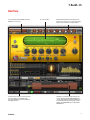


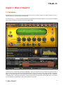
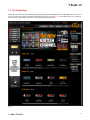


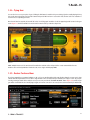


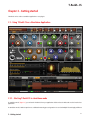

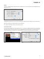
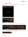


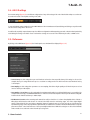


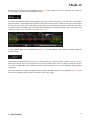


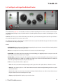

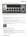

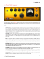

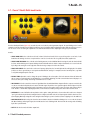


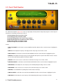


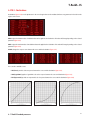


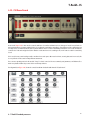


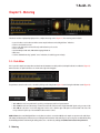


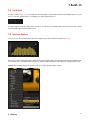


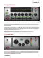


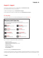


![Overture 2 Owner`s Manual [US]](http://vs1.manualzilla.com/store/data/005690862_1-0f7bb48baaf3473aa086657512069e12-150x150.png)