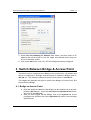
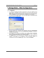
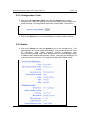
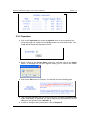
1
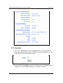
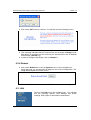
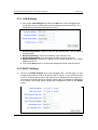
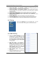
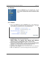
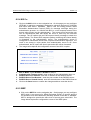
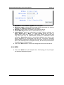
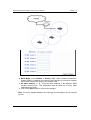
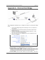
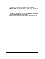
Wireless Multi-Client
Bridge / Access Point / Repeater
User’s Manual
Version: 1.4
Wireless Multi-Client Bridge / Access Point / Repeater
Version 1.4
Table of Contents
1
INTRODUCTION .................................................................................................................... 5
1.1
1.2
1.3
1.4
2
UNDERSTANDING THE HARDWARE .................................................................................. 9
2.1
2.2
2.3
3
TCP/IP CONFIGURATION ................................................................................................ 10
SWITCH BETWEEN BRIDGE & ACCESS POINT ...............................................................11
4.1
4.2
5
HARDWARE CONFIGURATION ............................................................................................ 9
HARDWARE INSTALLATION ................................................................................................ 9
DEFAULT IP ADDRESS ....................................................................................................... 9
PC CONFIGURATION.......................................................................................................... 10
3.1
4
FEATURES & BENEFITS ..................................................................................................... 5
PACKAGE CONTENTS ........................................................................................................ 6
APPLICATIONS .................................................................................................................. 6
NETWORK CONFIGURATION............................................................................................... 7
BRIDGE TO ACCESS POINT ...............................................................................................11
ACCESS POINT TO BRIDGE .............................................................................................. 13
BRIDGE MODE – WEB CONFIGURATION ........................................................................ 14
5.1
LOGGING IN .................................................................................................................... 14
5.2
SYSTEM ......................................................................................................................... 15
5.2.1 Administrator Settings.............................................................................................. 16
5.2.2 Firmware Upgrade ................................................................................................... 16
5.2.3 Configuration Tools.................................................................................................. 17
5.2.4 Status ....................................................................................................................... 17
5.2.5 Operation ................................................................................................................. 18
5.2.6 Reboot ..................................................................................................................... 19
5.3
LAN .............................................................................................................................. 19
5.3.1 LAN Settings ............................................................................................................ 19
5.3.2 DHCP Settings......................................................................................................... 20
5.4
WIRELESS ...................................................................................................................... 20
5.4.1 General .................................................................................................................... 20
5.4.2 Advanced ................................................................................................................. 21
5.4.3 WPA ......................................................................................................................... 22
5.4.4 WEP ......................................................................................................................... 23
6
ACCESS POINT MODE – WEB CONFIGURATION ........................................................... 24
6.1
LOGGING IN .................................................................................................................... 24
6.2
SYSTEM ......................................................................................................................... 25
6.2.1 Administrator Settings.............................................................................................. 25
6.2.2 Firmware Upgrade ................................................................................................... 26
6.2.3 Configuration Tools.................................................................................................. 26
6.2.4 Status ....................................................................................................................... 26
6.2.5 Operation ................................................................................................................. 27
6.2.6 Reboot ..................................................................................................................... 28
6.3
LAN .............................................................................................................................. 28
6.3.1 LAN Settings ............................................................................................................ 29
6.3.2 DHCP Settings......................................................................................................... 29
6.4
FILTERING ...................................................................................................................... 30
6.4.1 MAC Filtering ........................................................................................................... 30
Page 2 of 43
Wireless Multi-Client Bridge / Access Point / Repeater
Version 1.4
Table of Contents
6.5
WIRELESS ...................................................................................................................... 31
6.5.1 General .................................................................................................................... 31
6.5.2 Advanced ................................................................................................................. 32
6.5.3 WPA ......................................................................................................................... 33
6.5.4 802.1x ...................................................................................................................... 34
6.5.5 WEP ......................................................................................................................... 34
6.5.6 WDS......................................................................................................................... 35
APPENDIX A – POINT-TO-POINT BRIDGE................................................................................. 37
APPENDIX B – POINT-TO-MULTIPOINT BRIDGE...................................................................... 39
APPENDIX C – SPECIFICATIONS............................................................................................... 41
APPENDIX D – FCC INTERFERENCE STATEMENT ................................................................. 43
Page 3 of 43
Wireless Multi-Client Bridge / Access Point / Repeater
Version 1.4
Revision History
Version
1.0
1.1
1.2
1.3
1.4
Date
September 15, 2003
October 1, 2003
January 29, 2004
August 31, 2004
December 10, 2004
Notes
Initial Version
Updated GUI
Modified System, Status, WPA screen captures
Add examples for ptp / ptmp bridge and repeater
Updated screen captures, examples and specs
Page 4 of 43
Wireless Multi-Client Bridge / Access Point / Repeater
Version 1.4
1 Introduction
The Wireless Multi-Client Bridge/Access Point/Repeater operates seamlessly in the
2.4 GHz frequency spectrum supporting the 802.11b (2.4GHz, 11Mbps) and the
newer, faster 802.11g (2.4GHz, 54Mbps) wireless standards. It's the best way to add
wireless capability to your existing wired network, or to add bandwidth to your
wireless installation.
To protect your wireless connectivity, it can encrypt all wireless transmissions
through 64/128-bit WEP data encryption and also supports WPA.. The MAC address
filter lets you select exactly which stations should have access to your network. With
the Wireless Multi-Client Bridge/Access Point/Repeater, you'll experience the best
wireless connectivity available today.
This chapter describes the features & benefits, package contents, applications, and
network configuration.
1.1 Features & Benefits
Features
Benefits
High RF Output Power
More coverage of regular Multi-Client Bridge.
IEEE 802.11b/g Compliant
Fully Interoperable with IEEE 802.11b/
IEEE802.11g compliant.
Point-to-point, Point-to-multipoint
Wireless Connectivity
Allows users to transfer data between multiple
buildings.
Plug and Play
No driver needed, quickly and easily connects
your Ethernet device to Wireless.
Power-over-Ethernet
Flexible Access Point locations and cost savings.
64 /128-bit WEP data encryption
Powerful data security.
Hide SSID (AP Mode)
Avoids unauthorized users from sharing the
bandwidth and increases efficiency of the network.
DHCP Client/ Server
Simplifies network administration.
WDS (Wireless Distribution System)
Configures wireless AP and Bridge mode
simultaneously as a wireless repeater.
MAC address filtering (AP Mode)
Ensures secure network connections.
Seamless Roaming
Allows users to roam between APs without losing
their network connection.
Page 5 of 43
Wireless Multi-Client Bridge / Access Point / Repeater
Version 1.4
1.2 Package Contents
h
h
h
h
h
One Client Bridge/Access Point/Repeater
One Power Adapter
One CAT 5 UTP Cable
One Fast Start Guide
One CD-ROM with User’s Manual Included
1.3 Applications
The wireless LAN products are easy to install and highly efficient. The following
list describes some of the many applications made possible through the power
and flexibility of wireless LANs:
a) Difficult-to-wire environments
There are many situations where wires cannot be laid easily. Historic
buildings, older buildings, open areas and across busy streets make
the installation of LANs either impossible or very expensive.
b) Temporary workgroups
Consider situations in parks, athletic arenas, exhibition centers,
disaster-recovery, temporary offices and construction sites where one
wants a temporary WLAN established and removed.
c) The ability to access real-time information
Doctors/nurses, point-of-sale employees, and warehouse workers can
access real-time information while dealing with patients, serving
customers and processing information.
d) Frequently changed environments
Show rooms, meeting rooms, retail stores, and manufacturing sites
where frequently rearrange the workplace.
e) Small Office and Home Office (SOHO) networks
SOHO users need a cost-effective, easy and quick installation of a
small network.
f) Wireless extensions to Ethernet networks
Network managers in dynamic environments can minimize the
overhead caused by moves, extensions to networks, and other
changes with wireless LANs.
g) Wired LAN backup
Network managers implement wireless LANs to provide backup for
mission-critical applications running on wired networks.
h) Training/Educational facilities
Training sites at corporations and students at universities use wireless
connectivity to ease access to information, information exchanges,
and learning.
Page 6 of 43
Wireless Multi-Client Bridge / Access Point / Repeater
Version 1.4
1.4 Network Configuration
To better understand how the wireless LAN products work together to create a
wireless network, it might be helpful to depict a few of the possible wireless LAN
PC card network configurations. The wireless LAN products can be configured as:
a) Ad-hoc (or peer-to-peer) for departmental or SOHO LANs.
b) Infrastructure for enterprise LANs.
a) Ad-Hoc (peer-to-peer) Mode
This is the simplest network configuration with several computers
equipped with the PC Cards that form a wireless network whenever they
are within range of one another. In ad-hoc mode, each client is peer-topeer, would only have access to the resources of the other client and
does not require an access point. This is the easiest and least expensive
way for the SOHO to set up a wireless network. The image below depicts
a network in ad-hoc mode.
Page 7 of 43
Wireless Multi-Client Bridge / Access Point / Repeater
Version 1.4
b) Infrastructure Mode
The infrastructure mode requires the use of an access point (AP). In this
mode, all wireless communication between computers has to be via the
AP. It doesn’t matter if the AP is stand-alone or wired to an Ethernet
network. If used in stand-alone, the AP can extend the range of
independent wireless LANs by acting as a repeater, which effectively
doubles the distance between wireless stations. The image below
depicts a network in infrastructure mode.
Page 8 of 43
Wireless Multi-Client Bridge / Access Point / Repeater
Version 1.4
2 Understanding the Hardware
2.1 Hardware Configuration
h
h
h
RJ-45 Ethernet Connector – Provides 10/100 Mbps connectivity to a
wired Ethernet LAN.
Reset Button – Unplug the device, hold down the reset button, and then
plug the power back in. Notice that the three LEDs are solid green.
Release the reset button after 5 seconds. The device will then reboot into
its default configuration (Bridge: 192.168.1.1)
Note: All previous settings will be lost
Power Supply Connector – Connects to the power adapter.
2.2 Hardware Installation
A. Configure your notebook or PC with a wireless LAN card.
B. For a wired LAN, connect your PC’s Ethernet port to the AP’s LAN port via an
Ethernet cable.
C. For WLAN, position the Access Point in a proper location.
D. Plug in the power cord into the power outlet.
2.3 Default IP address
This device can be configured as a Bridge or an Access Point. By default, this
device is configured as a Bridge, and the default IP address in Bridge mode is:
192.168.1.1. The default IP address for Access Point mode is: 192.168.1.2.
In order to switch between Bridge and Access Point modes refer to Chapter 4 –
Switch Between Bridge & Access Point.
Page 9 of 43
Wireless Multi-Client Bridge / Access Point / Repeater
Version 1.4
3 PC Configuration
3.1 TCP/IP Configuration
Follow the steps below in order to configure the TCP/IP settings of your PC.
A. In the Control Panel double click Network Connections, and then double
click on the connection of your Network Interface Card (NIC). You will then
see the following screen.
B. Select Internet Protocol (TCP/IP) and then click on the Properties button.
This will allow you to configure the IP address of your PC. You will then see
the following screen.
Page 10 of 43
Wireless Multi-Client Bridge / Access Point / Repeater
Version 1.4
C. Select Use the following IP address radio button, and then enter an IP
address and subnet mask for your PC. Make sure that the device and your
PC is on the same subnet.
D. Click on the OK button, your PC’s TCP/IP settings have been configured.
4 Switch Between Bridge & Access Point
This device can be configured as a Bridge or an Access Point. By default, this
device is configured as a Bridge, and the default IP address in Bridge mode is:
192.168.1.1. The default IP address for Access Point mode is: 192.168.1.2.
This chapter will describe the steps to switch from Bridge to Access Point, and
Access Point to Bridge.
4.1 Bridge to Access Point
a. Enter the default IP address of the Bridge into the address bar of the webbrowser (192.168.1.1). Leave the user name and password fields blank,
and click on the OK button.
b. After you have logged into the Bridge, click on the System link on the
navigation bar, and then click on the Operation link under it, as the image
depicts below.
Page 11 of 43
Wireless Multi-Client Bridge / Access Point / Repeater
Version 1.4
c. Place a check in the Access Point check box, and then click on the
Apply button. A message box will then appear asking you to confirm the
switch.
d. Click on the OK button to continue. You will then see the following page.
e. This message indicates that the firmware has now changed to Access
Point mode. After about 15 seconds you can re-launch you web-browser
to the IP address of the Access Point (192.168.1.2)
Page 12 of 43
Wireless Multi-Client Bridge / Access Point / Repeater
Version 1.4
4.2 Access Point to Bridge
a. Enter the default IP address of the Access Point into the address bar of
the web-browser (192.168.1.2). Leave the user name and password
fields’ blank, and click on the OK button.
b. After you have logged into the Access Point, click on the System link on
the navigation bar, and then click on the Operation link under it, as the
image depicts below.
c. Place a check in the Bridge check box, and then click on the Apply
button. A message box will then appear asking you to confirm the switch.
d. Click on the OK button to continue. You will then see the following page.
e. This message indicates that the firmware has now changed to Bridge
mode. After about 15 seconds you can re-launch you web-browser to the
IP address of the Access Point (192.168.1.1)
Page 13 of 43
Wireless Multi-Client Bridge / Access Point / Repeater
Version 1.4
5 Bridge Mode – Web Configuration
5.1 Logging In
h
h
h
h
h
To configure the Bridge through the web-browser, enter the IP address of the
Bridge (default: 192.168.1.1) into the address bar of the web-browser and press
Enter. Make sure that the Bridge and your computers are on the same subnet.
Refer to Chapter 3 in order to configure the IP address of your computer.
You will then see the login window. Leave the User name and Password fields
blank and click on the OK button.
You can change the username and password under the Administrator
Settings option. Refer to section 5.2.1 Administrator Settings to change the
username and password.
After logging in, you will see the Graphical User Interface (GUI) of the Bridge.
The configuration is divided into three major parts: System, LAN, and Wireless.
Each one is described in detail in the next few sections.
The Status page is the first page that is displayed; this page displays the
settings of the Bridge, the IP addresses, and the Wireless settings. To
understand more about the Status page, refer to section 5.2.4 Status.
Page 14 of 43
Wireless Multi-Client Bridge / Access Point / Repeater
Version 1.4
5.2 System
Click on the System link on the navigation bar. You will
then see the following options: Administrator Settings,
Firmware Upgrade, Configuration Tools, Status, Operation,
and Reboot. Each option is described in detail below.
Page 15 of 43
Wireless Multi-Client Bridge / Access Point / Repeater
Version 1.4
5.2.1 Administrator Settings
h Click on the Administrator Settings link under the System menu on the
navigation bar. On this page you can configure a user name and password
for the Bridge. The image below depicts the administrator settings screen.
h User name: enter a new user name.
h Administrator Password: enter a new password in the first box, and then
re-type the password in the second box.
h Click on the Save button to confirm the changes and then reset the device.
5.2.2 Firmware Upgrade
h Click on the Firmware Upgrade link under the System menu on the
navigation bar. Using this page you can upload a new firmware on the Bridge.
The image below depicts the Firmware Upgrade screen.
h Click on the Browse button to select the firmware, and then click on the
Upload button.
h The upload may take up to 60 seconds to complete. Do not power off the
device while the upgrade is in process.
Page 16 of 43
Wireless Multi-Client Bridge / Access Point / Repeater
Version 1.4
5.2.3 Configuration Tools
h Click on the Configuration Tools link under the System menu on the
navigation bar. Using this page you can reset the settings of the Bridge to its
factory defaults. The image below depicts the Configuration Tools screen.
h Click on the Reset button to reset the Bridge to its factory default settings.
5.2.4 Status
h Click on the Status link under the System menu on the navigation bar. This
page displays the current status of the Bridge. This includes information such
as: connection state, SSID, channel number, transmission rate,
communication strength, WEP, WPA, Bridge name, number of Bridged clients,
IP address, MAC address and firmware version. This page also displays a list
of Access Points in the area. The image below depicts the Status screen.
Page 17 of 43
Wireless Multi-Client Bridge / Access Point / Repeater
Version 1.4
5.2.5 Operation
h Click on the Operation link under the System menu on the navigation bar.
Using this page can switch from the Bridge mode to Access Point mode. The
image below depicts the Operation screen.
h Place a check in the Access Point check box, and then click on the Apply
button. A message box will then appear asking you to confirm the switch.
h Click on the OK button to continue. You will then see the following page.
h This message indicates that the firmware has now changed to Access Point
mode. After about 15 seconds you can re-launch you web-browser to the IP
address of the Access Point (192.168.1.2)
h In order to configure the Access Point, refer to Chapter 6.
Page 18 of 43
Wireless Multi-Client Bridge / Access Point / Repeater
Version 1.4
5.2.6 Reboot
h Click on the Reboot link under the System menu on the navigation bar.
Using this page you can reset the bridge based on the current configuration.
The image below depicts the Reset screen.
h Click on the Reboot button to reset the bridge based on its current
configuration.
5.3 LAN
Click on the LAN link on the navigation bar. You will then
see the following options: LAN Settings and DHCP
Settings. Each option is described in detail below.
5.3.1 LAN Settings
h Click on the LAN Settings link under the LAN menu on the navigation bar.
Using this you can configure the local IP settings on the bridge. The image
below depicts the LAN Settings screen.
h
h
h
h
Device Name: enter a name for the bridge.
Default IP Address: enter the IP address.
Default Subnet Mask: enter the subnet mask.
Default Gateway: enter the IP address of the default gateway. The default IP
Page 19 of 43
Wireless Multi-Client Bridge / Access Point / Repeater
Version 1.4
address is 0.0.0.0.
h Click on the Save button to confirm the changes and then reset the device.
5.3.2 DHCP Settings
h Click on the DHCP Settings link under the LAN menu on the navigation bar.
Using this you can configure this bridge as a DHCP client, meaning that the
network will assign the IP address to it.
h DHCP Client Mode: select Disable or Enable. By enabling this option, the
network will assign an IP address to the Bridge.
h Click on the Save button to confirm the changes and then reset the device.
5.4 Wireless
Click on the Wireless link on the navigation bar. You will
then see the following options: General, Advanced, WPA
and WEP. Each option is described in detail below.
5.4.1 General
h Click on the General link under the Wireless menu on the navigation bar.
Using this page you can configure the wireless settings such as: wireless
mode, SSID, channel, and transmission rate. The image below depicts the
General Wireless screen.
Page 20 of 43
Wireless Multi-Client Bridge / Access Point / Repeater
Version 1.4
h Wireless Network Type: select Point to Multi-Point or Point to Point from
the drop-down list. Use Point to Multi-Point to connect to a wireless AP, or
use Point to Point to connect to another Bridge or Station.
h Wireless Network Name (SSID): the SSID is a unique name shared among
all points in your wireless network. The SSID must be identical for all points in
the network. It is case sensitive and must not exceed 32 characters.
h Desired BSSID: enter the MAC address of the AP or Bridge. If you leave this
field blank, then the Bridge will connect to the AP with the strongest signal.
h Channel: select a radio frequency from the drop-down list.
h Transmission Rate (Mbits/s): select a transmission rate from the drop-down
list.
h Wireless Mode: select a connection mode from the drop down list. Options
available are 802.11g Only, 802.11g Only (Maximum Performance),
802.11b/g Mixed Mode Long, and 802.11b Only.
h Click on the Save button to confirm the changes and then reset the device.
Note: Refer to Appendix A & B for a detailed example of this section.
5.4.2 Advanced
h Click on the Advanced link under the Wireless menu on the navigation bar.
Using this page you can configure the cloning mode and threshold values.
The image below depicts the Advanced Wireless screen.
Page 21 of 43
Wireless Multi-Client Bridge / Access Point / Repeater
Version 1.4
h Cloning Mode: select WLAN Card to set the MAC address of the bridge (as
seen by the Access Point and other wireless devices) to the MAC address of
the WLAN card inside the bridge. Select Ethernet Client to set the MAC
address to be that of the first Ethernet client that transmits data from behind
the Bridge.
h Fragmentation threshold: transmitted wireless packets larger than this size
will be fragmented to maintain performance in noisy wireless networks.
h RTS threshold: transmitted wireless packets larger than this size will use the
RTS/CTS protocol to (a) maintain performance in noisy wireless networks
and (b) prevent hidden nodes from degrading performance.
h Maximum burst time: the amount of time the radio will be reserved to send
data without requiring an ACK. Adding a burst time should help throughput
for 802.11g clients when the Bridge is running in mixed mode. This number is
in units of microseconds. A typical value would be 1000 microseconds. When
the value if 0, bursting is disabled.
h Click on the Save button to confirm the changes and then reset the device.
5.4.3 WPA
h Click on the WPA link under the Wireless menu on the navigation bar. On
this page you may configure WPA, an acronym for Wi-Fi Protected Access,
which is a security protocol from the Wi-Fi alliance for 802.11 wireless
networks. It uses the Temporal Key Integrity Protocol (TKIP) to provide
stronger encryption than the earlier WEP (Wired Equivalent Privacy) method.
Derived from, and a subset of, the IEEE 802.11i security standard, WPA
includes 802.1x authentication. The image below depicts the configuration
screen of the WPA option.
h WPA Mode: select Disable or Enable for WPA.
h PSK Pass-Phrase: leave this blank if the stations will be supplied a key by
the 802.1x authentication server. If not, enter a pass-phrase between 8 and
63 characters.
h WPA Multicast Cipher Type: select TKIP, none, or WEP from the dropdown list.
h WPA Pairwise Cipher Type: select TKIP, none, or WEP from the dropdown list.
h Click on the Save button to confirm the changes and then reset the device.
Page 22 of 43
Wireless Multi-Client Bridge / Access Point / Repeater
Version 1.4
5.4.4 WEP
h Click on the WEP link under the Wireless menu on the navigation bar. On
this page you may configure WEP, which is an acronym for Wired Equivalent
Privacy, a security protocol for Wireless Local Area Networks (WLANs)
defined in the 802.11 standard. WEP is designed to provide the same level of
security as a wired LAN. The image below depicts the configuration screen
of the WEP option.
h WEP Mode: select Disable or Enable WEP encryption.
h WEP key length: select a WEP key length from the drop-down list. Options
available are 64-bit and 128-bit.
h WEP key: enter the WEP key. If you use WEP you must specify the same
key into the Access Point and wireless stations. For 64-bit keys you must
enter 10 hex digits. For 128-bit keys you must enter 26 hex digits. A hex
digit is either a number from 0 through 9 or a letter from A through F. Leaving
the box blank indicates a key of all 0’s.
h Default WEP key to use: select a default WEP key to use.
h Authentication: select an authentication method. Options available are
Open, Shared Key. An open system allows any client to authenticate as
long as it conforms to any MAC address filter policies that may have been set.
All authentication packets are transmitted without encryption. Shared Key
sends an unencrypted challenge text string to any device attempting to
communicate with the AP. The device requesting authentication encrypts the
challenge text and sends it back to the access point. If the challenge text is
encrypted correctly, the access point allows the requesting device to
authenticate.
h Click on the Save button to confirm the changes and then reset the device.
Page 23 of 43
Wireless Multi-Client Bridge / Access Point / Repeater
Version 1.4
6 Access Point Mode – Web Configuration
6.1 Logging In
h
h
h
h
h
To configure the Access Point through the web-browser, enter the IP address of
the Access Point (default: 192.168.1.2) into the address bar of the web-browser
and press Enter. Make sure that the Access Point and your computers are on
the same subnet. Refer to Chapter 3 in order to configure the IP address of
your computer.
You will then see the login window. Leave the User name and Password fields
blank and click on the OK button.
You can change the username and password under the Administrator
Settings option. Refer to section 6.2.1 Administrator Settings to change the
username and password.
After logging in, you will see the Graphical User Interface (GUI) of the Bridge.
The configuration is divided into four major parts: System, LAN, Filtering, and
Wireless. Each one is described in detail in the next few sections.
The Status page is the first page that is displayed, this page displays the
settings of the Access Point, the MAC/IP addresses, and the Wireless settings.
To understand more about the Status page, refer to section 6.2.4 Status.
Page 24 of 43
Wireless Multi-Client Bridge / Access Point / Repeater
Version 1.4
6.2 System
Click on the System link on the navigation bar. You will
then see the following options: Administrator Settings,
Firmware Upgrade, Configuration Tools, Status, Operation,
and Reboot. Each option is described in detail below.
6.2.1 Administrator Settings
h Click on the Administrator Settings link under the System menu on the
navigation bar. On this page you can configure a user name and password
for the Access Point. The image below depicts the administrator settings
screen.
h User name: enter a new user name.
h Administrator password: enter a new password in the first text box, and
then re-type the password in the second text box.
h Click on the Save button to confirm the changes and then reset the device.
Page 25 of 43
Wireless Multi-Client Bridge / Access Point / Repeater
Version 1.4
6.2.2 Firmware Upgrade
h Click on the Firmware Upgrade link under the System menu on the
navigation bar. Using this page you can upload a new firmware on the
Access Point. The image below depicts the Firmware Upgrade screen.
h Click on the Browse button to select the firmware, and then click on the
Upload button.
h The upload may take up to 60 seconds to complete. Do not power off the
device while the upgrade is in process.
6.2.3 Configuration Tools
h Click on the Configuration Tools link under the System menu on the
navigation bar. Using this page you can reset the settings of the Access
Point to its factory defaults. The image below depicts the Configuration Tools
screen.
h Click on the Reset button to reset the Access Point to its factory default
settings.
6.2.4 Status
h Click on the Status link under the System menu on the navigation bar. This
page displays the current status of the Access Point. This includes
information such as: AP name, MAC address, number of associated stations,
IP address, SSID, WEP, and WPA. The image below depicts the Status
screen.
Page 26 of 43
Wireless Multi-Client Bridge / Access Point / Repeater
Version 1.4
6.2.5 Operation
h Click on the Operation link under the System menu on the navigation bar.
Using this page can switch from the Access Point mode to Bridge mode. The
image below depicts the Operation screen.
h Place a check in the Bridge check box, and then click on the Apply button. A
message box will then appear asking you to confirm the switch.
Page 27 of 43
Wireless Multi-Client Bridge / Access Point / Repeater
Version 1.4
h Click on the OK button to continue. You will then see the following screen.
h This message indicates that the firmware has now changed to Bridge mode.
After about 15 seconds you can re-launch you web-browser to the IP address
of the Bridge (192.168.1.1)
h In order to configure the Bridge, refer to Chapter 5.
6.2.6 Reboot
h Click on the Reboot link under the System menu on the navigation bar.
Using this page you can reset the AP based on the current configuration. The
image below depicts the Reset screen.
h Click on the Reboot button to reset the AP based on its current configuration.
6.3 LAN
Click on the LAN link on the navigation bar. You will then
see the following options: LAN Settings and DHCP
Settings. Each option is described in detail below.
Page 28 of 43
Wireless Multi-Client Bridge / Access Point / Repeater
Version 1.4
6.3.1 LAN Settings
h Click on the LAN Settings link under the LAN menu on the navigation bar.
Using this you can configure the local IP settings on the Access Point. The
image below depicts the LAN Settings screen.
h Access Point Name: enter a name for the access point. This is different
from the SSID.
h Default IP Address: enter the IP address of the Access Point.
h Default Subnet Mask: enter the subnet mask for the Access Point.
h Default Gateway: enter the IP address of the default gateway. The default
address is 0.0.0.0.
h Click on the Save button to confirm the changes and then reset the device.
6.3.2 DHCP Settings
h
Click on the DHCP Settings link on the navigation bar. On this page you can
configure this Access Point as a DHCP client or server. If you set this Access
Point as a DHCP client, then it will receive its IP address from the network. If
you choose to set this device as a DHCP server, then it will assign IP addresses
to its clients. The image below depicts the configuration screen of the DHCP
option.
Page 29 of 43
Wireless Multi-Client Bridge / Access Point / Repeater
h
h
h
h
h
h
h
h
Version 1.4
DHCP Client Mode: select Disable or Enable. By enabling this option, the
network will assign an IP address to the Access Point.
DHCP Server Mode: select Disable or Enable. If you enable DHCP Server,
then the Access Point will assign IP addresses to the clients based on address
ranges specified.
DHCP Address Range Start: enter the starting range for the IP addresses.
DHCP Address Range End: enter the ending range of the IP addresses.
DHCP Timeout in Minutes: enter a lease time for the IP addresses. This is
specified in minutes.
Primary DNS Server: enter the IP address of the primary DNS server.
Secondary DNS Server: enter the IP address of the secondary DNS server.
Click on the Save button to confirm the changes and then reset the device.
6.4 Filtering
Click on the Filtering link on the navigation bar. You will
then see the MAC Filtering option, as described below.
6.4.1 MAC Filtering
h
Click on the MAC Filtering link on the
navigation bar. On this page you may
list the MAC addresses of clients that
you wish to allow or disallow association
by the Access Point. This image depicts
the configuration screen of the MAC
Filtering option.
h
MAC Filter Mode: select Disable or
Enable. By enabling MAC filtering, only
the listed MAC addresses will be able to
associate with the Access Point. By
disabling MAC filtering, only the listed
MAC addresses will not be able to
associate with the Access Point.
MAC address 1~25:
list the MAC
addresses.
Click on the Save button to confirm the
changes and the rest the device.
h
h
Page 30 of 43
Wireless Multi-Client Bridge / Access Point / Repeater
Version 1.4
6.5 Wireless
Click on the Wireless link on the navigation bar. You will
then see the following options: General, Advanced, WPA,
802.1x, WEP, and WDS. Each option is described in detail
below.
6.5.1 General
h Click on the General link under the Wireless menu on the navigation bar.
On this page you can manage 802.11b/g of the Access Point. The image
below depicts the configuration screen of the General option.
h Visibility Status: select Visible or Invisible. This option displays or hides
the SSID of this Access Point from other devices.
h Wireless Mode: select an Access Point mode from the drop down list.
Options available are 802.11g Only, 802.11g Only (Maximum
Performance), 802.11b/g Mixed Mode Long, and 802.11b Only,
h Wireless Network Name (SSID): the SSID is a unique name shared among
all points in your wireless network. The SSID must be identical for all points in
the network. It is case sensitive and must not exceed 32 characters.
h Channel: select a radio frequency from the drop-down list.
h Transmission Rate (Mbits/s): select a transmission rate from the drop-down
list.
h Click on the Save button to confirm the changes and then reset the device.
Page 31 of 43
Wireless Multi-Client Bridge / Access Point / Repeater
Version 1.4
6.5.2 Advanced
h Click on the Advanced link on the navigation bar. On this page you may
configure the maximum associated stations, thresholds, beacon periods,
DTIM interval, maximum burst time, PSM mode. The image below depicts the
configuration screen of the Advanced option.
h Fragmentation Threshold: transmitted wireless packets larger than this size
will be fragmented to maintain performance in noisy wireless networks.
h RTS Threshold: transmitted wireless packets larger than this size will use
the RTS/CTS protocol to (a) maintain performance in noisy wireless networks
and (b) prevent hidden nodes from degrading performance.
h Beacon Period: Access Point beacons are sent out periodically. This is the
number of milliseconds between each beacon.
h DTIM Interval: this is the number of beacons per DTIM (Delivery Traffic
Indication Message), e.g. '1' means send a DTIM with each beacon, '2'
means with every 2nd beacon, etc.
h Maximum Burst Time: this is also known as PRISM Nitro (tm) technology.
The technology uses fully standards-compliant methods that eliminate
collisions in mixed-mode networks, while greatly increasing the performance
of both pure 802.11g and mixed 802.11b/g networks. The setting is for the
amount of time the radio will be reserved to send data without requiring an
ACK. This number is in units of microseconds. A typical value would be 1000
microseconds. When this number is zero, bursting is disabled.
h PSM Mode: turn this on to enable support for stations in power save mode.
h Isolation: this is another security feature. By enabling this, the stations
associated with the AP will not be able to see each others shared files.
h Output Power: select an output power from the drop-down list.
h Click on the Save button to confirm the changes and then reset the device.
Page 32 of 43
Wireless Multi-Client Bridge / Access Point / Repeater
Version 1.4
6.5.3 WPA
h Click on the WPA link on the navigation bar. On this page you may configure
WPA, an acronym for Wi-Fi Protected Access, which is a security protocol
from the Wi-Fi alliance for 802.11 wireless networks. It uses the Temporal
Key Integrity Protocol (TKIP) to provide stronger encryption than the earlier
WEP (Wired Equivalent Privacy) method. Derived from, and a subset of, the
IEEE 802.11i security standard, WPA includes 802.1x authentication. The
image below depicts the configuration screen of the WPA option.
h WPA Mode: select Disable or Enable for WPA.
h PSK Pass-Phrase: leave this blank if the stations will be supplied a key by
the 802.1x authentication server. If not, enter a pass-phrase between 8 and
63 characters.
h WPA Multicast Cipher Type: select TKIP, none, or WEP from the dropdown list.
h WPA Pairwise Cipher Type: select TKIP, none, or WEP from the dropdown list.
h WPA Group Key Update Interval: this is the time period for WPA and WPAPSK to update the WPA group key value. It is recommended to leave this
value at its default: 3600 seconds.
h Click on the Save button to confirm the changes and then reset the device.
Page 33 of 43
Wireless Multi-Client Bridge / Access Point / Repeater
Version 1.4
6.5.4 802.1x
h
h
Click on the 8021.x link on the navigation bar. On this page you may configure
IEEE 802.1x, which is a standard is designed to enhance the security of WLANs
that follow IEEE 802.11 standards. 802.1x uses an existing protocol called
Extensible Authentication Protocol (EAP) for message exchange during the
authentication process. In a WLAN with 802.1x, a user requests access to the
access point (known as the authenticator). The access point forces the user
into an unauthorized state that allows the client to send only an EAP-start
message. The AP replies with an EAP-request identify message to obtain the
clients identity. The clients EAP-response packet containing the clients identity
is forwarded to the authentication server. The authentication server is
configured to authenticate clients with a specific authentication algorithm. The
result is an accept or reject packet from authentication server to AP. Once
authenticated, the AP opens the client’s port and traffic will be forwarded
The image below depicts the configuration screen of the 8021.x option.
h
h
h
h
h
h
802.1x Mode: select Disable or Enable for 802.1x
Authentication Timeout (mins): enter a value for the authentication time out.
RADIUS Server IP Address: enter the IP address of the RADIUS server.
RADIUS Server Port Number: enter the port number of the RADIUS server.
RADIUS Server Shared Secret: enter the shared secret of the RADIUS server.
Click on the Save button to confirm the changes and then reset the device.
6.5.5 WEP
h Click on the WEP link on the navigation bar. On this page you may configure
WEP, which is an acronym for Wired Equivalent Privacy, a security protocol
for Wireless Local Area Networks (WLANs) defined in the 802.11 standard.
WEP is designed to provide the same level of security as a wired LAN. The
image below depicts the configuration screen of the WEP option.
Page 34 of 43
Wireless Multi-Client Bridge / Access Point / Repeater
Version 1.4
h WEP Mode: select Disable or Enable WEP encryption.
h WEP Key Length: select a WEP key length from the drop-down list. Options
available are 64-bit and 128-bit in HEX and ASCII.
h WEP Key: enter the WEP key based on the selection above.
h Default WEP Key to Use: select a default WEP key to use.
h Authentication: select an authentication method. Options available are
Open, Shared Key or Both. An open system allows any client to
authenticate as long as it conforms to any MAC address filter policies that
may have been set. All authentication packets are transmitted without
encryption. Shared Key sends an unencrypted challenge text string to any
device attempting to communicate with the AP. The device requesting
authentication encrypts the challenge text and sends it back to the access
point. If the challenge text is encrypted correctly, the access point allows the
requesting device to authenticate.
h Click on the Save button to confirm the changes and then reset the device.
6.5.6 WDS
h Click on the WDS link on the navigation bar. On this page you may configure
the Wireless Distribution System.
Page 35 of 43
Wireless Multi-Client Bridge / Access Point / Repeater
Version 1.4
h WDS Mode: select Disable or Enable WDS. When Wireless Distribution
System (WDS) is enabled, the Access Point functions as a wireless repeater
and is able to extent the range of the wireless LAN
h AP MAC address 1 – 6: enter the MAC address of the adjacent WDS
capable Access Point. This information must be filled out on every WDS
enabled Access Point.
h Click on the Save button to confirm the changes.
Note: For every repeater added to the topology, the throughput will be reduced
by 50%.
Page 36 of 43
Wireless Multi-Client Bridge / Access Point / Repeater
Version 1.4
Appendix A – Point-to-Point Bridge
This configuration describes how to configure the device in point-to-point bridge
mode.
1. Connect each Bridge using the RJ-45 directly to a PC or to Switch for a
wired network.
2. Configure the PCs on the wired network to the same IP subnet as the
Bridge (192.168.1.x).
3. Connect to the Bridge using its default IP address (192.168.1.1), and
leave the username and password blank.
4. Once connected, click on the Wireless link on the navigation bar, and
then click on General.
h Wireless Mode: select Point to Point from the drop-down list.
h Wireless Network Name (SSID): the SSID is a unique name shared among
all points in your wireless network. The SSID must be identical for all points in
the network. It is case sensitive and must not exceed 32 characters.
h Desired BSSID: enter the MAC address of the peer Bridge. This field is
Page 37 of 43
Wireless Multi-Client Bridge / Access Point / Repeater
Version 1.4
optional.
h Channel: select a radio frequency from the drop-down list. Both Bridges must
be configured on the same channel.
h Transmission Rate (Mbits/s): select a transmission rate from the drop-down
list.
h Wireless Mode: select a connection mode from the drop down list. Options
available are 802.11g Only, 802.11g Only (Maximum Performance),
802.11b/g Mixed Mode Long, and 802.11b Only.
h Click on the Save button to confirm the changes and then reset the device.
Page 38 of 43
Wireless Multi-Client Bridge / Access Point / Repeater
Version 1.4
Appendix B – Point-to-Multipoint Bridge
This configuration describes how to configure the device in point-to-multipoint bridge
mode.
1. Connect each Bridge using the RJ-45 directly to a PC or to Switch for a
wired network.
2. Configure the PCs on the wired network to the same IP subnet as the
Bridge (192.168.1.x).
3. Connect to the Bridge using its default IP address (192.168.1.1), and
leave the username and password blank.
4. Once connected, click on the Wireless link on the navigation bar, and
then click on General.
h Wireless Network Type: select Point to Multi-point from the drop-down list.
h Wireless Network Name (SSID): the SSID is a unique name shared among
all points in your wireless network. The SSID must be identical for all points in
Page 39 of 43
Wireless Multi-Client Bridge / Access Point / Repeater
Version 1.4
the network. It is case sensitive and must not exceed 32 characters.
h Desired BSSID: enter the MAC address of the AP. If you leave this field
blank, then the Bridge will connect to the AP with the strongest signal.
h Channel: select a radio frequency from the drop-down list.
h Transmission Rate (Mbits/s): select a transmission rate from the drop-down
list.
h Wireless Mode: select a connection mode from the drop down list. Options
available are 802.11g Only, 802.11g Only (Maximum Performance),
802.11b/g Mixed Mode Long, and 802.11b Only.
h Click on the Save button to confirm the changes and then reset the device.
Page 40 of 43
Wireless Multi-Client Bridge / Access Point / Repeater
Version 1.4
Appendix C – Specifications
General
Data Rates *
1, 2, 5.5, 6, 9, 11, 12, 18, 24, 36, 48, 54 Mbps
Standards
IEEE802.11b/g, IEEE802.1x, IEEE802.3, IEEE802.3u
Compatibility
IEEE 802.11g/ IEEE 802.11b compliant
Power Requirements
Power Supply: 90 to 240 VDC ± 10% (depends on
different countries)
Device: 12 V/ 1A
Status LEDs
LAN: Link , WLAN: Link , Power: on/off
Regulation Certifications
FCC Part 15/UL, ETSI 300/328/CE
RF Information
Frequency Band
2.400~2.484 GHz
Media Access Protocol
Carrier Sense Multiple Access with Collision Avoidance
(CSMA/CA)
Modulation Technology
Orthogonal Frequency Division Multiplexing (OFDM)
DBPSK @ 1Mbps
DQPSK @2Mbps
CCK @ 5.5 & 11Mbps
BPSK @ 6 and 9 Mbps
QPSK @ 12 and 18 Mbps
16-QAM @ 24 and 36 Mbps
64-QAM @ 48 and 54 Mbps
Operating Channels
11 for North America, 14 for Japan, 13 for Europe,
2 for Spain, 4 for France
Receive Sensitivity
(Typical)
-94dBm @ 1Mbps -92dBm @ 6Mbps -83dBm @
24Mbps
-92dBm @ 2Mbps -90dBm @ 9Mbps -79dBm @
36Mbps
-89dBm @ 5.5Mbps -88dBm @ 12Mbps -74dBm @
48Mbps
-86dBm @ 11Mbps -86dBm @ 18Mbps -72dBm @
54Mbps
Available transmit power
(Depend on Different
Countries’ Regulation)
21 ± 2dBm @1, 2, 5.5 and 11Mbps
20 ± 2dBm @6, 9, 12, 18Mbps
17 ± 2dBm @24, 36Mbps
16 ± 2dBm @48, 54Mbps
RF Connector
TNC Type (Female Reverse)
Networking Information
Page 41 of 43
Wireless Multi-Client Bridge / Access Point / Repeater
Version 1.4
Topology
Ad-Hoc, Infrastructure
Operation Mode
Point-to-Point/ Point-to-Multipoint Bridge/ AP/ Client
Bridge/ Repeater
One 10/100Mbps RJ-45 LAN Port
Interface
Security
IP Auto-configuration
• IEEE802.1x / RADIUS Client (EAP-MD5/TLS/TTLS)
Support—AP Mode
• WPA -- Wi-Fi Protected Access
• PSK (Pre share key) with 64/ 128-bit WEP Key
• EAP-MD5/TLS/ TTLS authenticator (AP Mode)
support
• TKIP
• MAC address filtering (WLAN)
• Hide SSID in beacons
• Layer 2 Isolation
DHCP client/ server
Management
Configuration
Web-based configuration (HTTP)
Firmware Upgrade
Upgrade firmware via Web-browser
Physical
Dimensions (HxWxD)
Weight
125(L)mm * 108(W)mm * 31(H)mm
4.9 (L)in* 4.3(W)in * 1.2(H)in
350 g (0.8 lb.)
Environmental
Temperature Range
-10°C to 45°C (14°F to 113°F) - Operating
-40°Cto 70°C (-40°F to 158°F) - Storage
Humidity (non-condensing)
5%~95% Typical
* Theoretical wireless signal rate based on IEEE standard 802.11a, b, g of chipset used. Actual
throughput will vary. Network conditions and environmental factors lower actual throughput rate.
** All specifications are subject to change without notice.
Page 42 of 43
Wireless Multi-Client Bridge / Access Point / Repeater
Version 1.4
Appendix D – FCC Interference Statement
Federal Communication Commission Interference Statement
This equipment has been tested and found to comply with the limits for a Class B digital
device, pursuant to Part 15 of the FCC Rules. These limits are designed to provide
reasonable protection against harmful interference in a residential installation. This
equipment generates, uses and can radiate radio frequency energy and, if not installed and
used in accordance with the instructions, may cause harmful interference to radio
communications. However, there is no guarantee that interference will not occur in a
particular installation. If this equipment does cause harmful interference to radio or television
reception, which can be determined by turning the equipment off and on, the user is
encouraged to try to correct the interference by one of the following measures:
•
•
•
•
Reorient or relocate the receiving antenna.
Increase the separation between the equipment and receiver.
Connect the equipment into an outlet on a circuit different from that to which the
receiver is connected.
Consult the dealer or an experienced radio/TV technician for help.
This device complies with Part 15 of the FCC Rules. Operation is subject to the following two
conditions: (1) This device may not cause harmful interference, and (2) this device must
accept any interference received, including interference that may cause undesired operation.
FCC Caution: Any changes or modifications not expressly approved by the party responsible
for compliance could void the user's authority to operate this equipment.
IMPORTANT NOTE:
FCC Radiation Exposure Statement:
This equipment complies with FCC radiation exposure limits set forth for an uncontrolled
environment. This equipment should be installed and operated with minimum distance 20cm
between the radiator & your body.
This transmitter must not be co-located or operating in conjunction with any other antenna or
transmitter.
Page 43 of 43