1
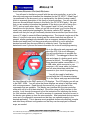
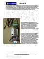
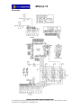
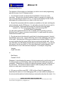
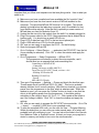
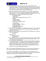
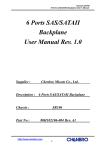
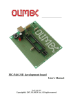
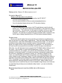
MODULE 11
MICROCONTROLLERS III
PREREQUISITES: MODULE 10: MICROCONTROLLERS II.
OUTLINE OF MODULE 11:
What you will learn about in this Module:
Use of a much more powerful microcontroller: the PIC16F877
In-circuit serial programming
Use of a microcontroller to drive an external peripheral device
Use of a standard display device (an LCD character display)
What you will build in the lab:
If you are registered for this course, the PC board that you need is already
built for you. You will need to check out the Module 11 test circuit from one of
the instructors. The schematic for this board is included, so that you can build
this circuit if you need to, or if you would like to modify the circuit for other
purposes. You will learn to program the microcontroller while it remains in the
circuit, and to display characters on an LCD dot matrix character display.
INTRODUCTION:
By now you should realize that microcontrollers are extremely versatile devices
that can be used for a wide range of applications. There are many different kinds of
microprocessors, some with considerably more features than others. For the last 2
modules you have been using a very basic variety of microcontroller, the sort of
device you might choose to control a simple toy or appliance. For this module you
will use a much more powerful microcontroller, built by the same manufacturer:
Microchip. You will also learn how to program the PIC16F877 without taking it out of
the circuit. This is called “in-circuit serial programming” (ICSP). It is a very
convenient feature if, for example, you can not remove the device from the circuit
because it is remotely located, in a hostile environment, hermetically sealed inside
an enclosure, implanted in an animal or human, etc. Because it remains in the
circuit, you can eliminate the IC socket and achieve very small package size by
using “surface mount” technology, that is, IC’s and components that solder directly to
one side of the printed circuit board (PCB), without wire leads that poke through the
PCB. By getting rid of the wire leads from components, you can reduce the size of
each component, and thus the entire circuit, by 50 to 90%. Many surface mount
components are so small that they can only be handled using forceps, and some are
so small that they actually pose a moderate safety hazard…you can accidentally
inhale them!
READINGS FROM HOROWITZ AND HILL (H&H): ART OF ELECTRONICS
None.
Copyright © Robert G. Dennis, the University of Michigan, 2004 ☺
This material may be freely copied and distributed for any educational purpose, but may not be sold for profit. Please
send comments and suggestions to: [email protected]
MODULE 11
ADDITIONAL READINGS & INTERNET RESEARCH:
You will need to familiarize yourself with the new microcontroller, so go to the
Microchip web page and download the datasheet for the PIC16F877. Read Page 1
(as numbered on the document, not as numbered by the Adobe Acrobat reader),
which is a general description of this family of microcontrollers. You will note that
there are several different devices in this family (the PIC16F87X family). Be sure
that you are reading information that pertains to the device you will be using (the –
F877), and not some other device. Flip to pages 8 and 9 to look over the pin
descriptions for this device. When you get the circuit board, you’ll notice that we
used a very small physical package for this device, called a QFP package. You
should note that you can get functionally identical microcontrollers (and most other
types of IC chips) in several different package sizes. The internal circuits are all the
same, it’s just the outer epoxy housing and the solder leads that are different. In
general, smaller packages are desirable from a consumer standpoint (they are
smaller and weigh less), but they are usually more difficult to use in prototype
devices because they are more difficult to solder by hand. Flip through the
datasheet to see if you can find some information on in-circuit serial programming.
Go to the Microchip web page and read
about the ICD-2 (in circuit debugger).
You will use this device to program the
PIC16F877. The debugger is about the
size and shape of a hockey puck, and is
pictured at the left. The debugger has
three electrical cables connected to it: (1)
a USB cable, which connects to your
computer, a 9V power cable (not shown),
and a 6-wire phone/data cable that
connects to your circuit for programming.
You will also need to familiarize
yourself with the LCD character display.
Go to the Optrex web page and download
the User Manual for the DMC-series of LCD displays. The LCD display you will use
is the DMC-16204. You will notice that these displays are setup to interface easily
with a microprocessor. Read through the manual so you get a sense for the
commands that are available. This display can interface with the microcontroller
either with a 4-bit or 8-bit data interface. We will be using an 8-bit interface in this
module. Look through the manual to find the instructions for initializing the device
for 8-bit interface operation. This will be a series of commands that must be sent to
the device upon power-up from the microcontroller. Most peripheral devices require
some sort of configuration commands so that they can operate properly in the
desired application. This is because most peripheral devices are relatively complex
and allow many different configurations so that they can be employed in different
ways, as needed.
Copyright © Robert G. Dennis, the University of Michigan, 2004 ☺
This material may be freely copied and distributed for any educational purpose, but may not be sold for profit. Please
send comments and suggestions to: [email protected]
MODULE 11
For this module you will need to check out the test circuit shown below from one of
the course instructors. The schematic for this circuit is shown on the following page.
In the photograph you will note that the circuit board is filled with many additional
components, including an SD memory card and a USB socket. For modules 11 and
8 you will not need these components, so they have been omitted from the
schematic and the physical circuit for these modules. This circuit is already built for
you if you are registered for this course, so you will only need to program and
operate the –F877 microcontroller. You will also note that there are some
unconnected wires on the test board cables. These allow you to connect to the
circuit in later modules using sensors, etc., so provided that the test board functions
properly for this module you can disregard any unconnected wires at this time.
Looking at the schematic, you will note that
many of the wires have been omitted, and
replaced by small flag symbols. This is a kind
of short hand that allows you to show
connections between established points on
components, or even between different pages
of very large schematics. A symbol that is
labeled “RB7” for example, is connected to
Register B7 on the microcontroller. Each
register on the microcontroller may be
connected to one or more connections on other
components. The label “nc” simply means “no
connection” when it is in one of the label flags.
Associated with a switch however, “nc” means
“normally closed”, that is, the switch is normally
connected to this pin if you are not pressing it.
Similarly for a switch “no” means “normally
open”, that is, not connected unless you press
the switch. For switches, the terminal labeled
“com” is the common terminal. The connection
between “com” and the other terminals is
switched depending on the state of the switch.
The components labeled “ribbon” are the
ribbon cable connectors on the PCB. The
rainbow-colored wires in the photograph are
the ribbon cables. The three components labeled “TLC4545” are 16-bit analog-todigital converters. They will be used in module 8, but for now you can just ignore
them.
Copyright © Robert G. Dennis, the University of Michigan, 2004 ☺
This material may be freely copied and distributed for any educational purpose, but may not be sold for profit. Please
send comments and suggestions to: [email protected]
MODULE 11
Schematic:
Copyright © Robert G. Dennis, the University of Michigan, 2004 ☺
This material may be freely copied and distributed for any educational purpose, but may not be sold for profit. Please
send comments and suggestions to: [email protected]
MODULE 11
When you check out and examine the circuit for this module you will also note that
the PCB has an unusual appearance…it is brown rather than green. This is
because it is a “4-layer” board. In addition to the signal traces on the top and bottom
of the board, there are two internal layers; a “ground” layer, and a “power” layer.
These are actually two additional solid layers of copper inside the PCB, which give
the translucent green board its brown appearance. If you have already completed
Module 15 (Hardware) you will know how to design and order a printed circuit board
using free software over the internet. This software is available from the
expresspcb.com web site. It includes the free software for drawing schematics
(ExpressSCH) as well as the free software for laying out and ordering the printed
circuit boards (ExpressPCB). Whether or not you have completed Module 15, you
might want to go to the ExpressPCB web page and read a bit about the use of 4layer PCBs. Briefly, 4-layer boards are very simple to make (but they cost a bit more
than 2-layer boards) and they have several distinct advantages: they eliminate the
need for ground and most power traces, thus allowing more compact PCB layout,
but more importantly they establish a large “ground plane”, which has the tendency
to reduce the unwanted noise in your circuit and generally just makes things work a
bit better. This usually does not matter for very simple circuits, but for more complex
circuits with low-level analog signals it can become very important. You can read
more about ground planes in H&H.
Copyright © Robert G. Dennis, the University of Michigan, 2004 ☺
This material may be freely copied and distributed for any educational purpose, but may not be sold for profit. Please
send comments and suggestions to: [email protected]
MODULE 11
SELF QUIZ
1: Go to the DigiKey web page and get some basic information on the LCD display that you
will use: the DMC-16204.
(a) How much does one of these displays cost?
(b) How lines of text and how many characters per line can it display?
(c) Is the data sheet for this device available on the DigiKey web page?
(d) Is the User Manual for this device available on the DigiKey web page?
2: How many I/O pins are available for use on the PIC16F877 microcontroller?
3: Describe the various I/O capabilities of the PIC16F877:
4: Over what voltage range can the PIC16F877 operate?
5: What are the advantages of establishing a ground plane in an electronic circuit?
PLEASE ANSWER THE ABOVE QUESTIONS AND E-MAIL TO THE INSTRUCTOR
“I have neither given nor received aid on this examination, nor have I concealed any
violation of the Honor Code”
X_______________________________________________________
Copyright © Robert G. Dennis, the University of Michigan, 2004 ☺
This material may be freely copied and distributed for any educational purpose, but may not be sold for profit. Please
send comments and suggestions to: [email protected]
MODULE 11
LABORATORY PROJECTS
The objective of this module is to familiarize you with in-circuit serial programming
and with the use of an LCD display module.
1- You will need to check out the test circuit for Module 11 from one of the
instructors. We only have a limited number of these, so please try to check it out
only on the day that you intend to use it. You can do the readings for this module
and prepare the software before you check out the test circuit.
2- Several files associated with this module are available on the web, including the
circuit schematic and the PCB layout. You will really only need the source code for
the microcontroller. Download the following file from the course web page:
module11.txt: This is the program that you will load using ICSP
(In-Circuit Serial Programming)
You will need to paste this text into the C compiler (PIC-C) just like you did for
Modules 9 and 10, save it as source code (module11.c) and compile the code to
create the file module11.hex
3- Plug the test circuit into the wall to verify that it is functioning properly. It should
automatically come to life. Colored LEDs may start to blink (depends on the version
of the code). Note that the LEDs are also surface mount devices (SMDs) so they
are much smaller than the normal LEDs that you are already familiar with. After a
very brief delay, the LED display should wake up and say something. If you are the
first group to use the test circuit, or if the circuit has been recently repaired, it will
have the name of one of the instructors displayed. For example, it might say:
Vicegrip
Fixed 3-20-2004
or
Bob Dennis
Created 3-10-04
Otherwise, it should display the names of the last students who used the test circuit.
If nothing comes up on the display, make sure that all of the cables are properly
connected. Failing that, you could try to debug the problem yourself, or find one of
the instructors. You should not have to build or solder anything for this module
unless you really want to (see end of module).
4: OK, now you will do some ICSP. ICSP (In-Circuit Serial Programming) is
essentially the same as in circuit debugging (ICD); you can modify the program on
the microcontroller and test it without having to remove the chip from the circuit. It is
Copyright © Robert G. Dennis, the University of Michigan, 2004 ☺
This material may be freely copied and distributed for any educational purpose, but may not be sold for profit. Please
send comments and suggestions to: [email protected]
MODULE 11
important that you follow a set sequence so that everything works. Here is what you
need to do:
A- Make sure you have compiled and have available the file “module11.hex”
B- Make sure you have the most recent version of MPLab installed on the
computer. This would be MPLab IDE Version 6.4 or higher. This should
already be installed on the laboratory computer, and it is available for free
from the Microchip web site. Note that this is probably a newer version of
MPLab than you used for Modules 9 and 10.
C- Unplug the test circuit for this module from the wall if it is already plugged in.
D- Plug in the power cable for the ICD-2 (the programmer that is shaped like a
hockey puck). You should see a green LED turn on.
E- Plug in ICD-2 data line from ICD-2 to the test circuit phone jack
F- Plug in USB cable from ICD-2 to the lab computer
G- OK, now you are ready to configure the ICD-2. Do the following:
H- Open the program MPLab IDE
I- Go to Configure → Select Device… → and select the PIC16F877 from the list
(it may already be selected). Click “OK” to close the window and apply the
settings.
J- Go to Programmer → Select Programmer → MPLab ICD 2
The programmer will attempt to detect the microcontroller, and it
should send you a message that looks something like:
Connecting to MPLAB ICD 2
...Connected
Setting Vdd source to MPLAB ICD 2
Target Device PIC16F877 found, revision = 0x6
...Reading ICD Product ID
Running ICD Self Test
...Passed
MPLAB ICD 2 Ready
K- Then go to Programmer → Settings → Power and check the box that says
“Power target circuit from MPLab ICD 2 (5V Vdd)”. This box is probably
already checked, but it is worth verifying. With this box checked, you provide
power from the programmer to the chip, which is what we want. While this
window is open, you can press the “Update” button to check to see that the
chip is in fact getting power from the programmer. It should be getting
something in the range of about 4.6 V to 5.1 V. Click update a few times to
see if the voltage is stable. Click “OK” to close the window and apply the
settings.
L- OK, now you are ready to program the PIC16F877 microcontroller. Go to File
→ Import… → module11.HEX (this is your compiled code).
M- To view the compiled HEX code, you can click on View → Program Memory.
Within this dialog box you can view your code several ways, all of which will
probably look very confusing to you. You can look at the code in the Opcode
Hex, Machine Code, or Symbolic format. At least you know your program is
stored in memory and ready to burn onto the microcontroller…
Copyright © Robert G. Dennis, the University of Michigan, 2004 ☺
This material may be freely copied and distributed for any educational purpose, but may not be sold for profit. Please
send comments and suggestions to: [email protected]
MODULE 11
N- Much more useful: you can view your source code by going to View →
Disassembly Listing. This will open a window to show you your source code,
and how this maps into the assembly language that is actually programmed
onto the device. You can just close these windows showing your code. You
don’t need to open them, but they are sometimes useful.
O- Mouse over the toolbar until you find the icon for “Program Target Device”.
Click once on this icon. This will cause the program to be burned into the
microcontroller. You can see what is happening as this process occurs…the
ICD-2 will update you with the following series of prompts:
Programming Target...
...Erasing Part
...Programming Program Memory (0x0 - 0x???)
Verifying...
...Program Memory
...Verify Succeeded
Programming Configuration Bits
.. Config Memory
Verifying configuration memory...
...Verify Succeeded
...Programming succeeded
MPLAB ICD 2 Ready
P- OK, if you see these prompts, then everything is going well. Now, unplug the
data cable from the phone jack on your test circuit, and then plug the test
circuit into a wall outlet.
Q- Within a couple of seconds you should see the LCD display come to life and
send you a message:
“Success”
Alternating with:
“Device has been
reprogrammed”
R- Now, study the source code for the program you just put onto the PIC16F877,
and then write out a flow chart that tells you what the program does so that
you understand the program flow.
S- Your assignment: print a message on the LCD that includes your name and
an exclamation mark (!). You will note that the character for an exclamation
mark is not included in the character set that I have defined for you at the
beginning of the source code, so you will have to look through the user
manual for the LCD Display to determine what the character code for the “!”
symbol is, and create an appropriate definition.
END: write a program that displays the names of your lab group and leave this on
the microcontroller so that they will be displayed for the next group of students.
If you feel the uncontrollable urge to build a similar circuit using surface-mount
devices and an LCD display, contact the instructors and we can set you up with the
necessary components and an appropriate PCB for prototyping.
Copyright © Robert G. Dennis, the University of Michigan, 2004 ☺
This material may be freely copied and distributed for any educational purpose, but may not be sold for profit. Please
send comments and suggestions to: [email protected]
MODULE 11
FEEDBACK
Was this Module useful and informative?
_________________________________________________________________
Is there a topic that should get more or better coverage?
_________________________________________________________________
In what way can this Module be improved:
Content: _________________________________________________
Depth of Coverage: _________________________________________
Style: ____________________________________________________
Any additional comments that will help us to improve this course:
__________________________________________________________
__________________________________________________________
__________________________________________________________
If you prefer, you may e-mail comments directly to Bob Dennis: [email protected]
Copyright © Robert G. Dennis, the University of Michigan, 2004 ☺
This material may be freely copied and distributed for any educational purpose, but may not be sold for profit. Please
send comments and suggestions to: [email protected]