1
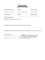
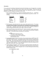
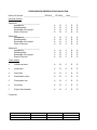
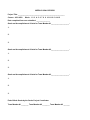
EE 4010/4020
SENIOR PROJECT WORKBOOK
by
Dr. Fon Brown
6 Aug 2014
Weber State University
Electronics Engineering
Ogden, Utah 84408-1703
Preface
The Department of Electronics Engineering has instituted the Senior Projects Program to help facilitate the
student's transition into industry and to provide a capstone experience in Electronics Engineering. The
program consists of two consecutive courses, EE4010 and EE4020.
Students should, either before starting EE4010 or within the first week thereafter, decide upon a project that
is both interesting to them and substantial enough to justify approximately 300 hours of effort (per student).
Students are expected to form teams of 2-3 members and to find a suitable advisor, preferably from the
industry relating to their project. (An employed student may work alone on a project of interest to his or her
employer, but an additional advisor will be required.)
During these two courses, students will develop a project plan, execute it, present design reviews, and
produce documentation. They will be graded on based on their ability to:
1. work as a team (appropriate division of labor, coordination with other team members),
2. manage their project (set and accomplish goals, keep to a schedule),
3. research, design and prototype, and
4. communicate, both by written document and formal presentation.
The purpose of this workbook is to clarify what is expected from each team and to provide guidelines that
have proven helpful to teams in the past.
Acknowledgement
This workbook is modeled on a similar workbook written by Dr. Bill Clapp, Former Chair of the Department
of Computer and Electronics Engineering Technology at Weber State University.
TABLE OF CONTENTS
1.0
2.0
3.0
4.0
5.0
6.0
7.0
8.0
9.0
10.0
11.0
12.0
13.0
14.0
15.0
PURPOSE OF SENIOR PROJECTS ........................................................... 1
COURSE DESCRIPTIONS ..................................................................... 2
SENIOR PROJECTS EVALUATION ........................................................... 3
ADVISORS ..................................................................................... 4
LOG BOOKS ................................................................................... 5
PROPOSAL .................................................................................... 6
PROJECT PLAN ............................................................................... 8
DESIGN REQUIREMENTS AND CONSTRAINTS .............................................. 9
DESIGN DOCUMENTATION .................................................................. 10
Design Document ............................................................................................................. 10
Research Paper ................................................................................................................ 11
Schematics ........................................................................................................................ 13
Code Listing ...................................................................................................................... 14
OTHER DOCUMENTATION ................................................................... 15
User’s Manual ................................................................................................................... 15
Parts List (Bill of Materials) ............................................................................................... 15
DESIGN REVIEWS ............................................................................ 17
TEAMWORK .................................................................................. 19
Share of the Load ............................................................................................................. 19
Meetings with Team Members .......................................................................................... 19
Meetings with Coordinator ................................................................................................ 19
PROJECT MANAGEMENT .................................................................... 20
Project Plan ....................................................................................................................... 20
Milestones ......................................................................................................................... 20
Weekly Goals .................................................................................................................... 20
RESEARCH AND DEVELOPMENT ........................................................... 22
Topical Research .............................................................................................................. 22
Circuit Design .................................................................................................................... 22
Problem Solving ................................................................................................................ 22
Circuit Construction ........................................................................................................... 23
Packaging ......................................................................................................................... 23
SPECIAL INTEREST ITEMS .................................................................. 24
1.0
PURPOSE OF SENIOR PROJECTS
The purpose of senior projects is to provide students with realistic project development experience similar to
what may be expected in industry. The senior project experience is divided into building skills in four major
areas: (1) teamwork, (2) project management, (3) research & development, (4) communication. These are,
in the author’s experience, the most important skill areas to the success of an engineer.
Teamwork:
Development projects typically take place in teams, and a productive team will always be greater than the
sum of its parts. Each member of a team must fulfill his or her share of the load, and ideally, improve the
performance of other members of the team. Team members must help each other both to define and to
accomplish the task of the team. In this course, team building situations naturally arise and students are
evaluated based on how they respond to those situations and their overall effectiveness as a team.
Project Management:
Delivering projects in a timely manner within budget is key to competitiveness in electronics and computer
related industries. Careful planning and execution of a project plan are very important to controlling
schedules, costs and features for development projects. Successful engineers have an understanding of
project management and its importance to the organization.
Research and Development:
Engineers must be technically competent to design circuits and systems to solve problems, but not all
designs need to start from scratch. Engineers must be able to perform research that leads to solutions and
they must be able to apply design principals learned elsewhere to the problem at hand. Furthermore,
engineers must be able to fabricate professional quality prototypes to implement and test their designs.
Basic knowledge of soldering, wire-wrapping, printed circuit design, and hardware skills are required for
well-built prototypes.
Communication:
Engineers must be able to clearly document their activities so others can easily understand what they have
done. Products require sufficient documentation that allows someone else to understand and modify the
product for different applications. Schematics and block diagrams must follow industry standards. Circuit
descriptions must be technically correct and easy to read.
Engineers must also be able to verbally communicate with clarity and ease of understanding. Presentation
skills are important for all engineers, particularly those working in teams.
2.0
COURSE DESCRIPTIONS
EE 4010
Senior Projects I (EE 4010) is the first course in the series of two required for graduation. EE 4010 is a two
credit hour class. The course requires the completion of the following significant milestones:
1.
2.
3.
4.
5.
6.
Form a Team
Proposal Approved
Project Plan Complete
Hardware Components in Hand
Critical Circuits Proven
Preliminary Design Review Complete
After the teams have been formed, each team will meet with the senior projects coordinator 20 minutes
each week. Students are expected to contribute about 10 hours per week for a total 150 hours during the
semester. A letter grade will be given at the end of the semester.
EE 4020
Senior Projects II (EE 4020) is the second course in the series required for graduation. EE 4020 is a two
credit hour class. The course requires the completion of the following significant milestones:
1.
2.
3.
4.
Proposal Obligations Fulfilled
Documentation Complete
Final Design Review Complete
Log Book Complete
Each team must meet with the senior projects coordinator 20 minutes each week. Students are expected to
contribute enough hours per week to meet schedule. A letter grade will be given at the end of the semester.
2
3.0
SENIOR PROJECTS EVALUATION
Each student or team is assigned a grade by the coordinator for the following criteria, then a grade point
average is computed for each student (in each of the four major areas). A weighted average of these
points is used to assign grades. Design review grades are taken from presentation evaluation forms.
Goal scores are based on weekly goal records.
Teamwork
1. Team Meetings
2. Meetings with Coordinator
3. Carrying Share of Load (Student #1)
4. Carrying Share of Load (Student #2)
5. Carrying Share of Load (Student #3)
EE 4010
(20%)
ABCDE
ABCDE
ABCDE
ABCDE
ABCDE
_____
_____
_____
EE 4020
(20%)
ABCDE
ABCDE
ABCDE
ABCDE
ABCDE
Project Management
1. Project Plan Document
2. Milestones Met
3. Weekly Goals Met (Student #1)
4. Weekly Goals Met (Student #2)
5. Weekly Goals Met (Student #3)
(30%)
ABCDE
ABCDE
______
______
______
Pts.
(20%)
Pts.
_____
_____
_____
ABCDE
______
______
______
_____
_____
_____
Research & Development
1. Topical Research
2. Circuit Design
3. Problem Solving
4. Circuit Construction
5. Packaging
(30%)
ABCDE
ABCDE
ABCDE
Pts.
(20%)
Pts.
ABCDE
ABCDE
ABCDE
ABCDE
_____
Communication
1. Log Book (Student #1)
1. Log Book (Student #1)
1. Log Book (Student #1)
2. Proposal (on time)
3. Prelim Design Review (Student #1)
4. Prelim Design Review (Student #1)
5. Prelim Design Review (Student #1)
6. Design Documentation
7. User’s Manual
8. Parts List (Bill of Materials)
9. Final Design Review (Student #1)
10. Final Design Review (Student #1)
11. Final Design Review (Student #1)
(20%)
ABCDE
ABCDE
ABCDE
ABCDE
______
______
______
Project On Schedule/Completed
Pass/Fail
Pass/Fail
Final Grade for ________(Student#1)
Final Grade for ________(Student#2)
Final Grade for ________(Student#3)
Semester and Year Completed
_______
_______
_______
_______
_______
_______
_______
_______
Pts.
_____
Pts.
(40%)
ABCDE
ABCDE
ABCDE
_____
_____
_____
Pts.
_____
_____
_____
ABCDE
ABCDE
ABCDE
______
______
______
3
Pts.
_____
_____
_____
4.0
ADVISORS
Each team needs advisors (mentors) to ensure that the educational goals of senior projects are
accomplished. Not only are advisors usually needed to ensure project completion; they are to be used to
improve the communication skills between students and engineers. Use of outside advisors also improves
relations between local industry and Weber State University.
The following criteria should be used concerning advisors:
1. Each team needs to find its own off-campus advisor*. The advisor should be an engineer in the field of
the team’s project or should at least be employed with a company in an engineering capacity. The advisor
must agree to provide assistance to the team in an advisory capacity only. The advisor must not get so
involved that the student learning objectives are compromised.
2. The advisor must be willing to attend the team’s senior project presentations (at the end of each
semester). The advisor will also become part of the evaluation team that grades the students.
3. Some teams may have more than one advisor. Each team (including advisors) must have a minimum of
three people, so if a student is doing a senior project without a classmate, a second advisor will be required.
For example, a lone employed student might have his or her immediate supervisor and another engineer
from the same company as the two advisors. Alternatively, larger teams may need to have two or more
advisors if their project is so diverse that one advisor is not enough.
4. Advisors should be treated as supervisors who only have a limited amount of time to devote to team
concerns. Advisors should generally be utilized for no more than 30 minutes each week. The students
should have the appropriate questions written down in advance before the advisor is contacted. The
students should be very careful not to abuse the advisor’s willingness to help.
5. EE Faculty members cannot be used as official advisors except in certain circumstances*, but they may
be available to help at their convenience. You should attempt to get help from your advisor(s) before turning
to the faculty.
*If the project is a cooperative effort with the Community Involvement Center, a faculty member may serve
as the advisor.
4
5.0
LOG BOOKS
Each member must keep an accurate log of his or her activities during the senior projects classes. Class
meetings, team meetings, phone calls, conversations, commitments, trips, ideas, schematics, calculations
and sketches should be recorded in your logbook along with the date and the amount of time spent on the
activity. These entries are to be made in a bound notebook in chronological order.
Your log book is a contemporaneous record of your activities and as such it is a legal document. If you
keep your log book using good documentation practices, it can be used in a court of law as evidence of your
work. A log book may save or cost an employer millions of dollars, depending on how it is kept.
Log books for EE 4010 and EE 4020 are required to follow the guidelines below:
1. Log books must be bound such that pages cannot be inserted or deleted without leaving
evidence. Three ring binders, spiral bound notebooks or books that use glue bindings are not
acceptable.
2. All pages must be numbered. If the log book does not have pre-printed page numbers, it is
acceptable to number each page by hand as it is used.
3. All work must be neat, legible and in ink.
4. Printed work may be included in the log book if it is glued or taped such that it cannot be
removed without leaving evidence.
5. Each page must be signed (or initialed) and dated as it is used. If a page contains work from
different dates, it must be separated with a horizontal line, and each section must be signed (or
initialed) and dated.
6. Blank pages or large blank spaces are not acceptable. If you wish to leave a blank page or large
blank space, draw a diagonal line from one corner to another, then initial and date it.
7. Do not obliterate. Obliteration is defined as (a) overwriting something, (b) scribbling out
something or (c) using white-out to cover something. The correct way to handle a small error is
to strike it out with a single horizontal line. For large errors, use a single diagonal line. If the
strikeout occurs on a different day, then it must also be initialed and dated.
8. Use your log book as a workbook. Do not transfer notes from scratch paper into your log book.
Write clearly; points are deducted for sloppy log books. Do not write on the back of a page except to strike it
out. (But exhibits such as datasheets or code listings may be affixed there.) Each day, the student should
take about five minutes per hour spent to summarize what was done and how much time it took. The
average size notebook (60 pages) should be about half full by the end of EE 4010 and completely full by the
end of EE 4020. The log books will be evaluated at the end of each semester.
5
6.0
PROPOSAL
The senior project must address a contemporary, unresolved issue or problem using the principals of
engineering design. Each team must write a proposal that clearly states the problem to be addressed, the
approach the team is taking to solve the problem and what the team will deliver when the project concludes.
The proposal must convince the faculty that the project is worthy of being a senior project, and all faculty
members in the department must approve and sign it. The proposal should clearly state what is to be
accomplished by the team to prevent any misunderstandings between the faculty and students. A draft of
the proposal is due for students in EE 4010 one week after classes begin and the signed copy is due one
week later.
The following guidelines should be used concerning proposals:
1. The proposal should be a one-page document that clearly describes the student commitment to the
project. Team goals and commitments should be clearly stated to avoid later confusion.
2. Team members and advisors must be listed including e-mail addresses and phone numbers. The
companies that the advisors work for must also be listed.
3. The proposal should be divided into three paragraphs. The first paragraph should define the problem to
be solved. The second paragraph should explain the theory or approach that will be used to solve the
problem. The third paragraph should explain the electronic circuits (and software) that will be developed
and delivered.
4. Single space using one-inch margins on the left and right.
5. The proposal must be error free. The students will be asked to correct any errors that are found on the
proposal.
6. The proposal must be approved and signed by all the members of the faculty in the Electronics
Engineering Program. The proposal must first be approved and signed by the senior project coordinator
before other faculty signatures are sought.
7. The original copy of the proposal must be given to the senior project coordinator for safe keeping in the
team folder. The students should make a copy of the signed proposal before giving the original to the
senior projects coordinator.
6
EXAMPLE PROPOSAL
<PROJECT TITLE> PROPOSAL
TEAM MEMBER’S NAME
________________________
________________________
________________________
ADDRESS
________________________
________________________
________________________
PHONE NUMBER
_________________
_________________
_________________
TEAM ADVISOR
________________________
COMPANY
________________________
PHONE NUMBER
_________________
PROJECT DESCRIPTION:
(Paragraph 1: Define the problem to be solved)
(Paragraph 2: Explain the theory of how the problem is going to be solved)
(Paragraph 3: Describe the hardware and software that will be presented at the conclusion of the project)
FACULTY APPROVAL:
___________________________
___________________________
___________________________
___________________________
_______
_______
_______
_______
DATE:
(Dr Kirk Hagen, Engineering Department Chair)
(Dr Justin Jackson, EE Program Coordinator)
(Dr. Fon Brown, Senior Projects Coordinator)
(Dr. Larry Zeng, Faculty)
7
7.0
PROJECT PLAN
Once your team is assembled and the proposal is signed, you will need to work on your project plan. Your
project plan is due by the end of the fifth week of EE 4010, but it is strongly recommended that you
complete it sooner. Once your project plan is complete, you should try very hard to stick to the schedule it
dictates. You will be graded on your ability to make a schedule then keep to it.
A project plan is a document that explains the scope of the project, a breakdown of the tasks necessary to
accomplish it and the resources required for each task. The project plan also provides a schedule for the
tasks (subject to the inevitable resource constraints) and gives a project timeline with a set of project
milestones.
Research (See Section 13) must be done concurrently while developing a project plan. The task
breakdown in the plan guides your research, and your research helps you estimate the time and resources
required for each task (which is necessary if you want an accurate schedule).
The project plan may be stored as an MS Project file or even an Excel document, but whichever format you
use, the document must contain the following four sections:
1. Scope of Project
This section describes the planned project, why it is being built and who the stakeholders are.
(Stakeholders are the people or organizations for whom the project is being built as well as those
who will operate, maintain or develop it. The list of stakeholders includes, at a minimum, your
team and your advisor(s).) This section explains the relationship of the project to the system in
which it will operate or to other systems with which it will interface. It also describes the role each
stakeholder will play in the development and maintenance of the project.
2. Project Tasks
This section is the heart of the project plan. It defines each task necessary to complete the project
in terms of its tangible inputs and outputs. An estimate of the resources, budget and time required
for each task must be included. Complicated tasks may be broken down into a task hierarchy if it
is helpful. Don’t forget to include time for things like debugging and system integration.
3. Task Schedule
Based on the inputs and outputs of Section 2 and the resource constraints that always exist, this
section schedules the tasks (gives them start and end dates). As a consequence of this schedule,
certain milestones will emerge, such as preliminary design review complete or prototype
fabrication complete. These milestones should be listed on a timeline included in this section.
4. Budget
This section lists all the required resources and expenditures required for the project. (This
normally includes engineering labor and overhead, but for senior projects, these two items would
be omitted.)
The project plan must be approved and signed by all the stakeholders then submitted to the senior
projects coordinator.
Keep in mind that the project plan is a “living document.” In other words, if a task takes more or less
time than estimated, the project plan should be updated to reflect a new schedule, and if the change to
the schedule is substantial, it should be reapproved by the stakeholders (an informal or verbal approval
is sufficient) and resubmitted to the senior projects coordinator.
8
8.0
DESIGN REQUIREMENTS AND CONSTRAINTS
All design efforts begin by enumerating the requirements and constraints. Requirements generally specify
what the design must do, whereas the constraints are specific limits that the design must not exceed.
Requirements may be categorized as functional, performance, usability, aesthetic, interface, etc. To
illustrate, consider the design of a smart-phone. An example of a functional requirement might be that the
phone must use a G4 network if one is available but fall back to a G3 network if not. A performance
requirement might specify how many applets may run simultaneously or the amount of time the phone
operates before the battery dies. A usability requirement may insist that buttons be a certain size or that the
menu of built-in tools be defined in a certain way. Generally, requirements come from the customer (the
stakeholder for whom the design is done).
Constraints, on the other hand, are limitations to which the design must adhere. Again, constraints fall into
numerous categories but the ones that are most likely to apply to your project are:
1. Cost (economic) Constraints – A design has many costs associated with it. First, there is the nonrecurring engineering cost (NRE) that includes the cost of research, tooling, licensure and, were this
not a senior project, the engineering labor. But that’s not all, there are parts cost, manufacturing
costs and overhead. As an added complication, these costs change with quantity, so often a an
analysis of the market is necessary before these costs can even be estimated. For your project, the
cost constraints boil down to the cost of any parts, shipping and licenses you need to purchase, and
these must fall within the budget set forth and approved in the project plan.
2. Physical Constraints – Often, it is required that a device fits in a certain volume or that it consumes
less than a certain amount of power. These constraints limit the physical properties of a device.
Returning to the smart-phone example, a physical constraint might be that the phone fit the same
sleeve as a previous version.
3. Scheduling (timing) Constraints – With most devices, particularly in today’s economy, it is crucial
that a device not hit the market late. In a matter of 6 months to a year, a cutting-edge technology
can become old and uninteresting. Hitting the market late can cost millions of dollars and can turn a
potentially successful product into a failure. It is important, therefore, that the project meet the
schedule set forth in the project plan. Moreover, for senior projects, failure to meet the project
schedule may have even more catastrophic results – that is a failure to graduate on time.
4. Safety Constraints – It is important that any device we design be safe if used properly. Exposed
electrical contacts or mechanical pinch-points are generally not acceptable. A device designed to
test pressure sensors, for example, may drive the sensor into a test fixture using a pneumatic ram.
If it is at all possible for the operator to get his fingers between the ram and the test fixture, it is
necessary to design an interlock to keep this from happening. Safety constraints cover a wide range
of human or animal health may address issues as diverse as burn hazards or muscle strain.
9
9.0
DESIGN DOCUMENTATION
Students in EE 4020 are required to document their project. Depending of the type of project, students may
choose to document their project either with an industry style design document or an academic research
paper. For design documents, the circuit schematic and code listing (if applicable) should be included as
appendices. For research papers, these are separate documents. The design documentation should be
completed two weeks before the end of EE 4020 so that it can be circulated to the faculty and the team’s
advisor(s) prior to the final design review (See Section 10). (Code listings may be omitted from the
circulated documents, but must be included in the copy turned in on the day of the design review.)
Design Document
The design document serves to fully document an engineering design and should be written in such a way
that an engineer with similar skill can understand, replicate or modify your design.
Format
The format of this document varies from one employer to the next, but a good design document will include,
at a minimum, the following sections:
1. Introduction
This section explains in general terms what your device is and what problem it solves.
2. Scope
This section defines the scope of the document. The scope tells the reader what the document
covers, and more important, what it doesn’t.
3. Design Overview
3.1. Requirements
This section enumerates the design requirements (i.e. what the device must do). Requirements
usually fall into sub-categories such as functional requirements, performance requirements,
interface requirements, etc. (See Section 8.) All the requirements should be testable (Item 5,
below).
3.2. Constraints
This section enumerates the design constraints (i.e. what limitations are imposed on the design).
Constraints include cost, physical, scheduling and safety constraints. Often, constraints are not
tested, per se. Instead, analysis of the design is used to verify that the constraints are satisfied.
3.3. Applicable Standards
This section lists the engineering standards applicable to the design (if any). Engineering
standards are part of many designs, particularly those that communicate electronically (e.g. use
USB, I2C, SPI, CAN, RS-232, Ethernet, etc.).
3.4. Dependencies.
This section specifies what external devices or supplies are required for a device to function (e.g. a
power supply, clock, or a microprocessor bus).
3.5. Theory of Operation
This section provides a high-level overview of the design, including block diagrams and possibly
flow charts. The section should explain what each block does and how the pieces fit together.
10
3.6. Design Alternatives
This section is optional and is included if some design alternatives were considered and
rejected. Each design alternative and the reason(s) for rejection should be presented.
4. Design Details
This section provides a level of detail sufficient for another engineer to understand and duplicate
your design. This section should not include complete schematics and code listings (those must
be in the Appendix), but if an excerpt from the schematic or code listing helps clarify a point, it
may be included as a figure. As a general rule, the design details section will constitute more
than half of the design document (excluding Appendices).
5. Testing
This section enumerates the tests that were performed to verify that the design meets the
requirements. Each test describes the test procedure, the expected results, the actual results
and the requirement(s) that it verifies.
6. Conclusion
This section summarizes test results and makes observations about the performance and
functionality of the design. Also, it is likely that you have acquired some insight that will improve
the design for next time. This section is a good place to put that kind of information.
7. References and Bibliography
This section lists the references to other works you used to write this document.
8. Appendices
This is the appropriate place to put items for reference only, such as full schematics, data sheets
and code listings.
You may add additional sections or reorganize if it is helpful, but do not omit any of these sections without
approval of the senior projects coordinator. You should endeavor to be as clear, concise and complete in
your documentation as possible. Engineers are not impressed with long, wordy descriptions when a short
and simple statement will do.
In addition to the design document, teams are encouraged (but not required) to summarize their design and
results on a poster suitable for submission to an undergraduate conference (e.g. NCUR or the OUR
Research Symposium). The poster will be printed and mounted at department expense, and afterwards
displayed in the hallway near the engineering department office. The design document should be completed
at least two weeks prior to the final design review so that it can be circulated to the faculty and the team’s
advisor(s) (See Section 10). The poster may be completed at any time (even after the semester ends).
Research Paper and Poster
In some cases (particularly where the student is interested in graduate school) a research paper that can be
published in an engineering journal is appropriate. Again, the paper needs to provide enough details about
the design that another engineer can duplicate the results, but the format differs from the design document
discussed earlier.
Format
Research papers are more focused on the problem that the design solves rather than the design itself, and
the circuit design itself becomes part of a larger approach to obtain data or solve a problem. Again, formats
differ, but the sections described on the following page are widely accepted.
11
1. Abstract
This is a single paragraph (usually 200 words or less) that summarizes the entire paper. Often, the
abstract is published in an index and it is only thing that is used in a database search. (A list of
keywords sometimes follows the abstract, and these are also used in database searches.)
2. Introduction
This section serves three purposes. It first introduces the subject in a broad and general way, then
with each succeeding sentence narrows the focus until it reaches the problem addressed by the
paper. Second, it includes a literature review that lists the seminal contributions of others scientists
and engineers to the problem outlined earlier. Third, it describes your specific contribution (i.e.
design) along with an overview of the rest of the paper.
3. Methods
This section describes the methods used solve the stated problem and the means of evaluating the
efficacy of the solution. Since the design is part of the solution, it is appropriate it describe it here.
Again, there is no set format, but another engineer or scientist should be able to duplicate your
results (Section 4) using the description of the design you provide in this section.
4. Results
This section describes the stimulus (test conditions) and the raw results obtained from the approach
(design) described in Section 3. Commentary about the meaning or efficacy of these results should
be reserved for the Discussion Section, below.
5. Discussion
This section interprets the results and discusses the efficacy of the approach in solving the original
problem. Topics of discussion might include: how do these results compare with other approaches,
how do the results compare with modeled or expected behavior, what is new and significant about
this approach, etc. The goal of this section is to interpret the results that lead to the main conclusion
of the paper.
6. This section does not introduce any new information or insights about the problem, methods and
results in this paper. Its main purpose is to succinctly highlight the important conclusions described
earlier.
7. Further Research (optional)
If your research or design has opened the doors to new problems or a different approach, you
should include a section that briefly describes the problem(s) to be solved or the (potentially
superior) approach to be taken.
8. Acknowledgements
This section should acknowledge those who funded the project as well as contributors who do not
rise to the level of author.
9. References
The paper should contain a list of references formatted according the requirements of the journal to
which it is submitted. You may not include a reference unless it is cited in the paper.
Again, you should endeavor to be as clear, concise and complete in your paper as possible. Additionally,
teams that elect to write a research paper are required to summarize their design and results on a poster
suitable for submission to an undergraduate conference (e.g. NCUR or the OUR Research Symposium).
The poster will be printed and mounted at department expense, and afterwards displayed in the hallway
near the engineering department office. The research paper should be completed at least two weeks prior
to the final design review so that it can be circulated to the faculty and the team’s advisor(s) (See Section
10). The poster need not be completed until the design review.
12
Schematics
For any electronic circuit design, the design document should include, in one of its appendices, a complete
set of schematics. These schematics must be drawn using CAD software. (There are many free
applications available that can be used for schematic capture, e.g. ExpressSCH or Eagle.) The following
guidelines should be followed for schematics in this course:
1. Each component should have a reference designator printed next to it. A reference
designator is a single letter abbreviation for that component along with the number. For
example:
Device Letter
Capacitors
Diodes
Resistors
Transistors
IC's
Connectors
Examples
C
D
R
Q
U
J
C1, C2, C3, ... ..Cx
D1, D2, D3, .....Dx
R1, R2, R3, .. ...Rx
Q1, Q2, Q3, ...Qx
U1, U2, U3, .....Ux
J1, J2, J3, .....Jx
2. Each component should also have the value or part number printed next to it. The values
for resistors and capacitors do not include the ohms symbol or the microfarad symbol
because the notes (see below) eliminate the need. All diodes and transistors require the 1N
or 2N number. Integrated circuits need a part number unless a legend is provided. All
reference designators and values go to the right or above the symbol.
3. Notes should be drawn in the lower left corner. Only two notes are needed assuming you
have resistors and capacitors in your circuit. Avoid using the notes sections to describe
other parts. The following notes are suitable for all schematics:
NOTES:
1. All resistance values are in ohms,
1/4 W, ±5%, unless otherwise noted.
2. All capacitance values are in microfarads,
unless otherwise noted.
4. Unused gates should be drawn on the bottom of the schematic between NOTES and LAST
REFERENCE USED sections. Unused gates should be drawn showing IC designators and
pin numbers. Each unused input should be tied high or low to prevent any inputs from
floating. This section documents that the unused gates have been taken care of to avoid
noise and oscillation problems. The unused gates section also becomes a directory of the
gates that may be used in future design changes.
5. The last reference designator used for each type of component needs to be listed in the
LAST REFERENCE USED section. This list documents the last reference used to reduce
the possibility of using a reference designator twice. Use the following format when listing
the last references used.
LAST REFERENCE USED:
C12
D4
R23
U12
13
6. Each integrated circuit needs a pin number and pin function by each pin connection. The
pin number goes outside the box above or to the right. The function of that pin should be
abbreviated and located inside the box. The pin function may be omitted for gates drawn
with standard logic symbols.
7. To the extent possible, reference designators should be assigned on a drawing from the left
to right and from the top to the bottom.
8. Avoid four-way interconnections. The only exceptions should be for transistor biasing
circuits and data lines.
9. Schematics that use more than one page should label nodes or use I/O markers for interpage connections.
Code Listing
For projects that require software or programmable logic, the design documentation should include a code
listing. The listing is a plain text file that includes the source code for the software or logic chip. The file
should include a file header (a set of comments at the top of the file), and the code should conform to some
basic rules:
1. The file header should include the file (module) name, the author’s name(s), the date and a
description of the software/logic module. A revision history is not required but is
recommended.
2. Each procedure, task, function or subroutine should have a header that names the inputs,
outputs and a description that explains what the subroutine does. For assembly language,
the header should also include which registers or memory locations are destroyed.
3. Use comments liberally. A good rule of thumb is that 40% of assembly code lines should
have or be comments. For higher level software languages or hardware description
languages, 25% is a more appropriate number.
4. Use symbolic constants where possible. Don’t use uncommented magic numbers. A literal
constant is okay if there is a comment that explains where it came from.
5. Don’t make self-evident comments. For example, the code: foo++; // increment foo
would not be acceptable.
14
10.0
OTHER DOCUMENTATION
Students in EE 4020 must provide two other documents to complete the documentation package for their
project. These documents must be turned in on the day of the final design review but need not be
circulated.
User’s Manual
While the design documentation fully documents your design, it is a very cumbersome way to figure out how
to install or use it. A better document for this purpose is a User’s Manual. This document need not be long,
but should fully explain to a non-engineer how to install and use your device. You may organize your user’s
manual in any way you think appropriate, but it is recommended that you look at several commercial user’s
manuals to get ideas.
Parts List (Bill of Materials)
The schematics in the design document need to be accompanied by a complete parts list. The parts list is
not normally included as part of the design document because it can change as prices change or as parts
are discontinued by one vendor and become available from another. The parts list should include the
following information:
1. Project Title
2. Date
Every time an item is changed on the parts list, be sure to put a new date on the parts list.
3. Reference Designators
List the parts in alphanumeric order by the reference designators.
4. Parts Descriptions
Parts descriptions should describe the part in detail. For example: Capacitor entries need
the value, tolerance, type of capacitor (electrolytic, mylar, etc.), voltage rating, axial or radial
lead, and lead distance.
5. Name of Manufacturer
List the company that actually made the part. Some parts (Radio Shack) are sold without
the manufacturer printed and should be listed as unknown.
6. Manufacturer's Part Number
List the actual number that would be used to order the part.
7. Vendor
List the company or source where the parts were purchased or obtained.
8. Cost
List the cost that was paid for the part.
15
SAMPLE PARTS LIST
Project Title:_____________________________________________ Date: _____________
Ref #
Part Description
Manufacturer/
Part Number
Vendor/
Cost
___________________________________________________________________________
___________________________________________________________________________
___________________________________________________________________________
___________________________________________________________________________
___________________________________________________________________________
___________________________________________________________________________
___________________________________________________________________________
___________________________________________________________________________
___________________________________________________________________________
___________________________________________________________________________
___________________________________________________________________________
___________________________________________________________________________
___________________________________________________________________________
___________________________________________________________________________
___________________________________________________________________________
___________________________________________________________________________
16
11.0
DESIGN REVIEWS
During the last week of EE 4010 and EE 4020, teams are required to schedule a design review.
For students in EE 4010, this is a preliminary design review, which means that the students should present:
1. the problem they are solving,
2. the research they have accomplished,
3. the design decisions they have made,
4. the schedule of tasks and milestones yet to be completed.
For Students in EE 4020, this is a final design review, which means that the students should present:
1. the problem they are solving,
2. their final design for the project,
3. test results that verify that the design solves the problem,
4. total cost of the project in manpower and dollars.
The design review presentations are the responsibility of the team. The team should follow the guidelines
below to ensure a smooth presentation:
1. Determine a location for the presentation and have that location approved by the senior
project coordinator. Students who are doing a project for a local company are encouraged
to make their presentations at the company. Reserve that facility for the presentation. For
on-campus presentations, the department secretary has the room schedules and she can
assist you in locating an empty room.
2. Determine a presentation time and invite, at a minimum, the faculty that signed the team’s
proposal and the advisor(s). Invite faculty, advisors, and guests well in advance of your
scheduled presentation (e.g. three weeks or more) so that scheduling conflicts can be
resolved. Extend a written invitation two weeks before the review (See item 3, below).
Remind attendees one week before your presentation and again the day before. Escort
service to the classroom is advised for those who have a reputation of being late or absent.
3. Two weeks before the design review, provide a written invitation to each faculty member and
advisor that you’ve invited. The written invitation should include the title, presenters, time,
date, and location of the design review. For final design reviews, a copy of the design
documentation must also be circulated for review at this time to the faculty who signed the
proposal and to the team’s advisor(s). The design documentation may be distributed via
hard copy or e-mail.
4. Practice your presentation before you attempt to give it officially to the faculty. It is always
obvious who has practiced and who has not. If you are planning to use the multimedia
equipment, it is important that you practice using it. Students are asked to make a
preliminary presentation to the senior project coordinator during one of the 30-minute
meetings. The senior project coordinator will make recommendations that should be
followed.
5. Prepare the room before the presentation. It is recommended that you reserve the room one
hour before the start time of your presentation to allow enough time to set up and test your
project. Obtain and try out the multimedia equipment to make sure that it is working
correctly. Room 401 is an excellent room for presentations because it is clean and can
easily be darkened for projector viewing. Avoid cluttered and hard to use rooms.
17
The recommended one-hour format for the presentation is as follows:
0:00 to 0:05
Hand out the presentation outlines to the faculty, advisors and guests. A
team member introduces the team, advisors, and guests to the faculty.
0:05 to 0:10
A team member presents the problem and explains any social, economic or
political ramifications it may have. He or she then describes the approach
the team is using or has used to solve it and what role the various team
members have in that solution.
0:10 to 0:25
Each team member presents his or her contributions to the project. .
Research into subject matter not covered in previous classwork should be
noted. Each member should clearly demonstrate knowledge of the circuits
or software he or she is or was responsible for designing and building
0:25 to 0:30
A team member concludes by summarizing the status of the project, how
well it performed (final design review only), what might have been done
better, and what challenges lie in the future.
0:30 to 0:40
The team members professionally demonstrate the project (or show video
thereof) and answer questions.
0:40 to 0:50
The team members, guests, and students leave the room so the faculty and
advisors can privately critique the presentation. The senior project
coordinator collects the evaluation forms.
0:50 to 0:60
The team is invited back into the room and the critique results are reviewed.
Note: For EE 4010, the log book(s) must be available for inspection before and after the presentation. For
EE 4020, the log books, the user’s manual and the parts list must be available for inspection before and
after the presentation.
The following items will be collected by the senior projects coordinator at the end of the final design review:
1. Log books from each team member.
2. Design documentation including schematics and code listings, if appropriate.
3. The User’s Manual and the parts list.
4. Evaluation forms from the other faculty and advisor(s).
18
12.0
TEAMWORK
The ability of engineers to work in teams is crucial to most employers. The senior project provides an
opportunity to develop team building skills. It is highly recommended that a team include engineers and
technologists from different disciplines The Engineering department has a cooperative agreement with
Electrical Engineering Technology so that EET students may sign up for CEET4010/4020 but join an
Electronics Engineering team. Having a technologist on the team is an invaluable asset when it comes time
to lay out circuit boards or fabricate circuits.
Team building skills are evaluated by the senior project coordinator based on the student’s performance in
the following areas:
Share of the Load
Each member of a team must carry his or her share of the load. Weekly goals are set by the team and the
senior project coordinator monitors progress. Goals should be set so that each member has about 10 hours
of work per week, but all team members are expected to contribute enough time to accomplish their weekly
goals. The hours logged and goal completion are indicators of whether or not a student is carrying their
share of the load. Students found not carrying their share of the load for more than a week may be removed
from the team or suffer a reduction in their teamwork grade.
Meetings with Team Members
The members are expected to meet regularly to set goals and accomplish tasks to complete the goals.
Each member must be willing to meet with the team on a regular basis. Meeting times must be arranged
that can accommodate each team member. Any students who do not attend team meetings must be
reported to the senior project coordinator immediately. Students may be removed from a team after missing
more than one team meeting. The senior project coordinator will assign a letter grade as a relative indicator
of whether or not the student was regularly meeting with the team. Each meeting missed will lower the
student's team meeting grade by a half letter grade.
Meetings with Coordinator
Each team will meet with the senior projects coordinator each week to keep the coordinator informed as to
the progress of the team. Weekly goals will be evaluated and a new weekly goal sheet will be given to the
coordinator. It is the team's responsibility to coordinate a meeting time with the senior projects coordinator.
Any student who misses meetings may be dropped from the team after two unexcused absences. Sickness
and accidents are considered a legitimate reason to miss a meeting and no penalty will result as long as the
other team members pick up the workload. The senior projects coordinator will assign a letter grade based
on the effectiveness of the meeting and the accomplishment of goals.
19
13.0
PROJECT MANAGEMENT
Project management involves forming a project development plan, then allocating time and resources to
execute the plan. Careful planning and execution is essential to the success of any engineering project.
Project Plan
Your project plan must be turned in to the senior project coordinator during (or prior to) your 20-minute
meeting in the sixth week of EE 4010. The coordinator will assign a grade based on its detail and
completeness. Plans that do not adequately break down the task(s) at hand or that do not schedule them
effectively may result in a poor grade. Each time the project plan changes substantially, the coordinator will
need a new copy to track your milestones, but the grade will remain unchanged.
Milestones
Once the project plan is complete, you should endeavor to meet the milestones it dictates. The senior
projects coordinator will monitor your progress based on the milestones in your plan. Inasmuch as this
is probably your first project, considerable latitude will be given if your miss one or two milestones, but if
the problem becomes habitual, expect to lose one grade letter (rubric page 3) for each major milestone
missed.
Weekly Goals
Each team should submit a Weekly Goal Record or use a very detailed milestone chart to outline their
progress when they meet with the senior projects coordinator. The sheet should be filled out before the
meeting with the coordinator starts. Make a copy of the goal sheet to keep and submit the original copy
to the senior projects coordinator.
The following items should be completed on the Weekly Goal Form (See Page 23):
1. Team Members. List the last names of the team members in alphabetical order.
2. Course number. List the name of the course you are currently taking (EE 4010 or EE 4020).
3. Week number. List the week that the goal record is turned in to the senior projects coordinator.
4. Date. List the date that the goal record was turned in to the senior projects coordinator.
5. Goals for Team Member #n. Number and list the goals for team member #n. The goals listed
should be what the team wants done for the week. These are team-generated goals, not senior
project coordinator directed goals. List the number of hours that you plan to spend on that
particular goal. Do not use the words "research", "write", or "troubleshoot" without clearly describing
what you are going to learn, write, or fix. Each goal must be measurable, that is to say that there
must be an objective way to tell if the goal has been accomplished.
6. Accomplishment Criteria for the Goal. Write a brief summary of how an objective observer could
know if the goal is accomplished or not.
20
The following are examples of suitable goals and accomplishment criteria:
A. Goal: Research three types of microprocessors and obtain the data sheets. Select
one to use for the project. (3 hrs)
Accomplishment Criteria: Copies of data sheets in hand. Rationale for choice
documented in logbook.
B. Draw a rough schematic of the microprocessor, RAM, and ROM sections. (4 hrs)
Accomplishment Criteria: Schematic documented in logbook
C. Write the circuit descriptions for the microprocessor, RAM, and ROM sections on a
word processor. (5 hrs)
Accomplishment Criteria: Document written and reviewed by all team members.
D. Wire-wrap the microprocessor, RAM, and ROM sections of the project. Check
continuity of connections. (7 hrs)
Accomplishment Criteria: Hardware wire-wrap completed. Individual connections
checked off schematic as part of continuity check.
A template for the weekly goal record can be found on page 23 of this workbook.
21
14.0
RESEARCH AND DEVELOPMENT
Research and Development skills are evaluated an attempt to measure the student’s abilities to solve
design problems.
Topical Research
Each team member will conduct basic research. Library or Internet search results should be recorded in
your log book and presented during weekly meetings with the senior projects coordinator. Research is
crucial and should dominate your time during the project planning phase. Once the plan is complete,
research is still necessary, but it will occupy a relatively small amount of your time.
Circuit Design
Each member of a team must display good design techniques. Teams are not expected to design circuits
that have never been designed before. Original circuit designs are unlikely and may not be the best for the
job. Most designs are usually a combination of existing circuits. Good research techniques should unveil
other circuit designs that could be used in your design. The use of other designs must be brought to the
attention of the senior project coordinator and your design document should credit the original designer.
Whether a design is original or not will not be the issue. The issue is whether or not the students
understand the circuit well enough to modify or troubleshoot it themselves. The senior projects coordinator
will assign a letter grade for the design and research effort by the students.
Problem Solving
Each member of the team and the team as a whole must present good problem solving techniques. During
the course of the project many problems will arise that must be solved by the team. Problem solving
techniques will be observed by the senior projects coordinator. The senior projects coordinator will assign a
letter grade to each student for his or her problem solving techniques.
22
Circuit Construction
Circuit construction skills are practiced and evaluated to improve the student's ability to construct quality
prototypes. Circuits can be constructed using any permanent or semi-permanent technique such as printed
circuit boards or wire-wrap. Use of solder-free prototype boards is not acceptable.
Good soldering skills are crucial to building prototypes. All solder connections must be made correctly. The
following guidelines should be followed:
1. Use only a quality 25 to 60 watt soldering iron.
2. Use either 60/40 or 63/37 rosin core solder.
3. Make sure that the connections are clean before soldering.
4. Clean all printed circuit (PC) board connections with flux remover after soldering.
5. Spray PC boards with protective polyurethane coating to prevent surface corrosion.
6. Cover all open connections with heat-shrink tubing. All high voltage connections must be
well insulated to prevent shock.
Packaging
Unless the project consists of a circuit board to be included inside an existing enclosure, all projects must be
packaged in a cabinet. The packaging must follow the guidelines given below:
1. Switches, controls, and indicators must be labeled on the cabinet front panel.
2. All 110 VAC operated devices should be fused with inline fuse holders.
3. All 110 VAC connections must be well insulated to prevent a shock hazard. Use heat shrink
tubing on all exposed connections.
4. Any wires passing through the case must have strain relief devices to prevent the wires from
shorting to the case. If the case is metal, grommets are required.
6. Mechanical bolts and nuts should have lock washers installed. Bolts should extend through
the nuts more than one thread but less than five threads.
7. All inter-wiring connections should be bound with cable ties.
23
15.0
SPECIAL INTEREST ITEMS
The following items are of special interest to students:
1. Students may take this class as CBE (community-based education) if the senior project satisfies the
requirements set forth by the Community Involvement Center (Sheperd Union Building Room 327). Projects
of this nature can often be funded by grants and faculty may serve as advisors. Students can also receive
an excellence in service award (which entails a certificate and an honorary cord to wear at graduation) if
they submit their hours to the Community Involvement Center.
1. Students should not begin working on a senior project until their project has been approved with a
completed proposal. Project approval can be granted before officially registering for EE 4010. This might
occur if a student wants to begin working on his or her project during the summer when senior projects is
not offered. Project approval may be given prior to the summer break and that would allow students to
begin their project.
2. Students earn individual grades for each senior projects class. Each grade, once earned, will not be
changed because of changed circumstances or by a project that was not completed. For example, if a
student fails to complete EE 4020, he or she will not have to repeat EE 4010.
3. A team may complete its project during EE 4010 if it presents both its preliminary and final design
reviews during the semester. If a team completes its project in EE 4010, they will earn the same grade for
EE 4020 without having to attend class or meetings. (There may also be a possibility that the requirement to
complete EE 4020 could be waived, but to do this, you would need to contact the EE Program Coordinator.)
4. Incomplete, "I", will only be given to students because of illness or accidents. Procrastination or
unforeseen design problems will not be rewarded by incomplete grades.
5. Students who realize that they will not make the end of semester deadlines should withdraw from the
course before the end of the seventh week. Students that realize that they will not make the end of
semester deadlines after the seventh week of the semester will be given the grade that they have earned.
Passing grades are seldom given to those who have not completed all of the requirements.
6. Have fun and make senior projects a worthwhile experience.
7. Feel free to share your thoughts and concerns about senior projects to the senior project coordinator.
Changes and improvements are made because of feedback from students, faculty, and advisors.
24
DESIGN REVIEW PRESENTATION EVALUATION
Name of Evaluator: _____________________ EE 4010___ EE 4020___ Date ________
Individual Grades
Student #1:_______________________
Appearance
Speaking ability.
Knowledge of the project.
Share of the load
A
A
A
A
B
B
B
B
C
C
C
C
D
D
D
D
E
E
E
E
Student #2:_______________________
Appearance
Speaking ability
Knowledge of the project
Share of the load
A
A
A
A
B
B
B
B
C
C
C
C
D
D
D
D
E
E
E
E
Student #3:_______________________
Appearance
Speaking ability
Knowledge of the project
Share of the load
A
A
A
A
B
B
B
B
C
C
C
C
D
D
D
D
E
E
E
E
Team Grades
1.
Invitation process
A
B
C
D
E
2.
Introduction
A
B
C
D
E
3.
Visual aids
A
B
C
D
E
4.
Presentation outline
A
B
C
D
E
5.
Presentation flow
A
B
C
D
E
6.
Conclusion
A
B
C
D
E
7.
Project demonstration
A
B
C
D
E
Comments:
Coordinator Use Only
Total Grade Points
Grade Point Average (÷44)
Student 1
Student 2
Student 3
WEEKLY GOAL RECORD
Project Title: ____________________________________________________
Course: 4010 4020
Week: 1 2 3 4 5 6 7 8 9 10 11 12 13 14 15
Date completed form was submitted: _______________
Goals and Accomplishment Criteria for Team Member #1____________________:
1.
2.
3.
Goals and Accomplishment Criteria for Team Member #2____________________:
1.
2.
3.
Goals and Accomplishment Criteria for Team Member #3____________________:
1.
2.
3.
End of Week Grade by the Senior Project Coordinator
Team Member #1 ________ Team Member #2 ________ Team Member #3 _______