1
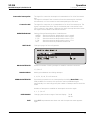
VP-128 MusicTAXI Layer 2/3 with 1 x S0 VP-128 User Manual V96/3.21 Businesspark Monrepos Monreposstraße 55 D-71634 Ludwigsburg Telefon: 07141/22660 Telefax: 07141/22667 2MBit: 07141/22380 Volksbank Heidenheim (BLZ 632 90110) Kto.-Nr.: 164 100 008 Swift Bank Code: DGZB DESG Handelsregister Ludwigsburg HRB 3695 1 Geschäftsführer: B. Burkhardtsmaier USt.-Id-Nr.: DE 146 187 117 VP-128 Table of Contents MusicTAXI Layer 2/3 with 1 x S0 Appliance documentation: Operation: DOD_0228/97-02... Digital Print by Project Vision (0 49) 7066 -910024 ... Display Codes and Error Messages: Introduction Installation/Connections Rear Panel Connectors Connectors/EMC Measures 3 4 5 7 General Getting Started Connection Set-up Connection Set-up/Try to Connect Connection Set-up/sync Indicator Disconnection Data Input Data Input - Audio Data Data Input - ISDN # Data Input - Connection Set-up ISDN # Data Input - Configuration Data Input - MSN/EAZ Data Input - G.722 Call Data Input - G.722 Service Indicator Data Input - Connection Remote Control Ancillary Data Alarm/Control Interface Lining Up Numeric Keypad 8 9 10 11 12 13 14 15 16 17 18 19 20 21 22 23 30 31 33 34 Status and ISDN Messages Status and ISDN Messages - 1TR6 Status and ISDN Messages - EURO System Reset Functions/Software Version 35 36 37 38 - All technical alteration are subject to change without further notice 2 VP-128 Appliance Documentation MusicTAXI Layer 2/3 with 1 x S0 Introduction: ISO/MPEG 11172-3: Introduction The Audio-ISDN appliance MusicTAXI type „VP-128“ from DIALOG4 is designed for stationary use. The MusicTAXI is compatible with ISO/MPEG 11172-3 and supports bidirectional Layer III and Layer II. The result is 2 x 15 kHz audio bandwidth using 2 B-Channels. This complies with the highest possible audio quality in conjunction with data reduction. G.722 / H.221: Moreover the MusicTAXI is compatible with the Philips 7 kHz telephone, supporting the standard G.722 and framing according to H.221. The MusicTAXI can establish a connection to a PKI telephone and vice versa. As soon as the device recognises that no MPEG data are being transmitted at an incoming call, the G.722 standard is loaded into the DSP’s automatically thus also establishing compatibility with the PKI telephone. G.711: ISDN D-Channel protocols: With the MusicTAXI a connection can be establish from and to nearly every analoque telephone (even GSM). Approx. 20 different D-Channel protocols are available for the MusicTAXI, allowing a world-wide use. The protocols 1 TR6 and ETSI are already integrated before the device leaves the manufacturer. These can be selected via the supervisor menu. USA: Master/Slave configuration: For the use of MusicTAXI at the American ISDN-network the protocol „National ISDN 1“ is available. The SPID-numbers are supported from MusicTAXI. The fact, that irrespective of place, configuration or baud rate, a connection via ISDN can be established fully automatically from just about anywhere in the world, is absolutely unique. The dialed appliance is always configured by the caller and transmission established. 3 VP-128 Appliance Documentation MusicTAXI Layer 2/3 with 1 x S0 Assembly: Installation/Connections The MusicTAXI is designed for installation into 19" racks (2 HU). Mounting with additional mounting rails is recommended because of the depth of the unit. The internal cooling design means that no additional distance to other apparatus is necessary. For mobile use there is an Alu suitcase available as an accessory. Rear connectors: REMOTE CONTROL (RS232): Serial, asynchronous interface for control of the MusicTAXI by an external PC. Setting of the interface: 9600 baud 8 data bits 1 stop bit no parity Connector: 9-pole Sub-D connector Pin assignment Function 1 2 3 4 5 6 to 9 NC RC_Tx RC_Rx NC GND NC Signal direction ref. to the MusicTAXI Output Input Ancillary Data: ANCILLARY DATA (RS232): Serial, asynchronous interface for transmission of user data via the MusicTAXI. Setting of the interface: 1200 baud 8 data bits 1 stop bit no parity Connector: 9-pole Sub-D connector Pin assignment Function 1 2 3 4 5 6 to 9 NC R_Tx R_Rx NC GND NC Signal direction ref. to the MusicTAXI Output Input 4 VP-128 Appliance Documentation MusicTAXI Layer 2/3 with 1 x S0 Rear Panel Connectors AUDIO Inputs/Outputs: AUDIO INPUT LEFT/RIGHT: Audio input balanced Level: Connector: Pin assignment: AUDIO OUTPUT LEFT/RIGHT: Connector: Pin assignment: AUDIO OUTPUT DIGITAL: S/PDIF-OUT: 1 2 3 GND IN (+) IN (-) Audio output balanced Level: AUDIO INPUT DIGITAL: -4dBu ..+20dBu adjustable (+12dBu factory preset) XLR female socket -4dBu ..+20dBu adjustable (+12dBu factory preset) XLR male socket 1 2 3 GND OUT (+) OUT (-) Digital input (AES/EBU Standard) Connector: XLR female socket Pin assignment: 1 2 3 GND IN (a) IN (b) Digital output (AES/EBU Standard) Connector: XLR male socket Pin assignment: 1 2 3 GND OUT (a) OUT (b) Digital output (S/PDIF Standard) Connector: RCA jack Pin configuration: Tip: OUT (a) Ring: OUT (b) S/PDIF-IN: Digital input (S/PDIF Standard) Connector: RCA jack Pin configuration: Tip: IN (a) Ring: IN (b) 5 VP-128 Appliance Documentation MusicTAXI Layer 2/3 with 1 x S0 Connectors DATA Interfaces: X.21: Serial, synchronous connection for transmission of the encoded audio data to external data communication equipment as well as for connection to a satellite modem. Baud rate: Connector: Pin assignment: 1 2 3 4 5 6 7 8 9 10 11 12 13 14,15 ISDN: ALARM/CONTROL: (INTERFACE) NC Tx (a) CTR (a) Rx (a) IND (a) CLK (a) NC GND Tx (b) CTR (b) Rx (b) IND (b) CLK (b) NC 32kbps to 384kbps 15-pol Sub-D connector Signal direction ref. to the MusicTAXI Output Output Input Input Input Output Output Input Input Input Standardized connector to the ISDN network. Baud rate: 2 x B + D-Channel Connector: RJ45 Pin assignment: Pin 3 Pin 4 Pin 5 Pin 6 TXa TXc RXc RXa The switching information at the inputs of the MusicTAXI is transferred and made available at the remote station as Open-Collector signals. The inputs and outputs are isolated via optocouplers. Input wiring: Imax: 10mA Output wiring: Imax: 6mA Umax: 25V 6 VP-128 Appliance Documentation MusicTAXI Layer 2/3 with 1 x S0 ALARM/CONTROL INTERFACE: Connectors/EMC Measures Connector: 25-pol Sub-D connector Pin assignment: Pin Signal 1 2 3 4 5 6 7 8 9 10 11 12 13 14 15 16 17 18 19 20 21 22 23 24 25 NC NC NC IN8 GND IN7 IN6 IN5 IN4 IN3 IN2 IN1 IN GND NC NC VCC OUT8 OUT7 OUT6 OUT5 OUT4 OUT3 OUT2 OUT1 OUT GND Recommended function: Red-Light IN Reset (Index) FF Rew Stop Record Play common ground for all inputs +5V Red-Light OUT Reset (Index) FF Rew Stop Record Play common ground for all outputs The different GND connections (5, 13, 25) are isolated from each other! Please note: EMC measures: The recommended functions of the inputs and outputs correspond with the assignment of different MusicTAXI users. This pin assignment should be used for problem-free remote control of the respective connected appliances during transmissions between different MusicTAXIs or . The pin assignment also corresponds to the function items of MT-Soft. Under consideration of the electromagnetic compatibility (EMC) the following factors should be observed as regards connections: Use screened cables for all connections. E.g. the well-known cable EMT 2111 is approved for audio cables. The screens are to be soldered to the named GND potentials or at the control/ interface cables to the „collar“ of the connector case. Use the respective NEUTRIK counter connectors/plugs for the 3-pole XLR plug/sockets as well. Also connect pin 4 (casing) with pin 1 in the plugs/sockets. 7 VP-128 Operation MusicTAXI Layer 2/3 with 1 x S0 Introduction: General The audio connection is set up in several steps: • Set-up of the ISDN lines (B-Channels) • Measuring and compensation of the B-Channel signal delay times • Data transfer between the ´s or MusicTAXI´s for setting the • desired mode of operation (Audio mode, sampling rate, etc.) • Start of the audio transmission In order to make using of the MusicTAXI as simple as possible, all the information necessary for transmission is entered and stored before the connection set-up. The data do not get lost if the appliance is switched off, which means that data for every remote station only need be entered once. The connection set-up is restricted to dialing a remote station from the stored list. Everything else takes place automatically. Key functions: The operation of the MusicTAXI takes place by means of menu control via the display and the keys UP, DOWN and ENTER. If these keys are pressed down permanently, the selected function is repeated until the key is released again. This is particularly advantageous when entering of abbreviated names. The desired function is selected from the displayed list with the UP and the DOWN keys. The selected function is indicated on the display in an inverted manner (i.e. light character font on dark background). Each time the UP key is pressed, the mark jumps up one line. Once the upper line is reached, the mark moves down to the bottom line the next time the key is pressed. In the same way, the mark moves downwards one line each time the DOWN key is pressed. The selected function is executed by pressing the ENTER key. The last display line serves to return to the previous menu and, depending on the function, for storing any input made. 8 VP-128 Operation MusicTAXI Layer 2/3 with 1 x S0 Getting Started Power-on procedure: The mains voltage selector is at the rear. The MusicTAXI adapts automatically to mains voltages between 90 and 240 VAC. After the start-up sequence the appliance performs a self-test of its individual components. During this procedure the address of DIALOG4 appears on the display. One second later the Layer III software is loaded into the memory registers of the digital signal processors (DSP). Each status of the DSP’s is indicated in the display: After the DSP’s are loaded with the current software, the version number of the hardware appears in the display: The first line shows the version number and the date of the system software (V3.21). The following lines show the version number of the ISDN controller (V1.57), the D-Channel protocol and the D-Channel country code. 49 = 1TR6 (Federal Republic of Germany) 99 = EURO ISDN This information remains visible for 1 second and can be „frozen“, when the ENTER key is kept pressed during the booting procedure. The version numbers now appear inverse, until ENTER is pressed once again. 9 VP-128 Operation MusicTAXI Layer 2/3 with 1 x S0 Main menu: Connection Set-up The loading procedure is now completed and the Audio ISDN unit switches to the main menu: The appliance is now ready to receive incoming calls or to establish a connection. Connection set-up: In order to transmit audio signals, select the item CONNECT in the main menu and press the ENTER key. Find the desired number in the displayed selection list and confirm with ENTER. The connection is now established and the MusicTAXI provides information on the current processes in the display. If the connection cannot be established, you can leave the directory by pressing the HANG-UP button. The two B-Channels are displayed as dark squares. The squares are always in the line, corresponding with the status of the respective B-Channel at the ISDN connection set-up. The dialed ISDN number is shown in the bottom line. DISC: B-Channel not connected (disconnected). CALL: Channel request runs in ISDN (Call). CON: Channel is connected. SYNC: REJ: B-Channels are synchronized to a data channel, the individual squares change into a single rectangle. If it was not possible to establish the connections, (rejected), the reasons therefore are displayed separately for both B-channels. 10 VP-128 Operation MusicTAXI Layer 2/3 with 1 x S0 Connection Set-up/Try to Connect An example: The different Error messages are explained in the chapter Display Codes and error Messages. Press the ENTER key to leave this display. You are now back in the MusicTAXI main menu. 1/3 Dial attempts: On the right top in the display the number of redialings (3) set and the attempts (1) appears. During the individual redialing attempts the last error message of ISDN is indicated in the display: This error message remains on the display for approx. 4 seconds before the information on the next redialing is displayed: If the connection set-up cannot be performed, the corresponding error message as described above appears in the display for each of the two B-Channels. Please note: If the given number of dialing attempts was performed unsuccessfully, the corresponding error message remains on the display until either the ENTER key is pressed or a call comes in. 11 VP-128 Operation MusicTAXI Layer 2/3 with 1 x S0 Connection is established: Connection Set-up/sync Indicator After successful connection set-up the display shows the message „ISDN connection established“ briefly and then jumps to the level display. The transfer can begin: The peak level is indicated, related to the maximum level at the input of the A/D converter. Overmodulations (CLIP) should be avoided on all accounts. As additional information the connection mode (X.21, ISDN or Local Loop) is indicated in the top line of the display, and the dialled ISDN # in the bottom line of the display. SYNC INDICATOR: EXIT: PREVIOUS MENU: (Back) If the audio decoder receives valid data, a filled-in square appears in the top right of the display. This square is not filled in if the remote unit is a decoder or if there is an error (e.g. if a not valid ISDN mode was pre-setted). The SyncIndicator is not shown when using G.722 or G.711 algorithm. The inverted displayed EXIT-Function is activated by pressing the ENTER key. A selection menu appears: The level display reappears. DATA INPUT: (enter data) You get into the AUDIO DATA menu and can alter your current settings (sampling rate, audio mode, audio source, baud rate and data transfer rate). The modifications are immediately effective after pressing EXIT, but,however, are not stored. Please note: Modifications in AUDIO DATA result in brief failures whilst the Encoder is being newly configured. DISCONNECT: The ISDN connection is disconnected. The MusicTAXI changes into the MAIN MENU and is ready to receive incoming calls. Disconnect can also be forced by pressing the HANG-UP button twice. 12 VP-128 Operation MusicTAXI Layer 2/3 with 1 x S0 Disconnection Disconnection of an existing connection: Press the ENTER key and select the item DISCONNECTION. Press the ENTER key again. The following message appears briefly: LOCAL DISCONNECT and the MusicTAXI is back in the MAIN MENU again. The message appears in the remote unit: REMOTE DISCONNECT and then the MAIN MENU again. Disconnection during dialing: If you have accidentally dialed a wrong ISDN number, you can interrupt the current dialing process by pressing the ENTER key. The following message appears briefly: ISDN CALL INTERRUPTED BY USER and then the MAIN MENU again. 13 VP-128 Operation MusicTAXI Layer 2/3 with 1 x S0 Data input: Data Input In order to establish a connection yourself, you must first of all enter and store the necessary data. Select the function DATA INPUT with the DOWN key and confirm with the ENTER key. The menu DIRECTORY appears: The list includes 64 possible entries (/1). Select an empty field and press ENTER. Now the display shows the data entry menu: Select AUDIO DATA ENCODER and press ENTER. A list of the default audio data appears. If you want to take over these defaults, move the cursor to EXIT and confirm with ENTER. Modifying the setting: To modify the settings move to the corresponding parameter. You can alter the default value by pressing the ENTER key. After the parameters have been altered, leave the menu with EXIT (+ENTER key). /1. Note: Entries #64 is reserved for the configuration. 14 VP-128 Operation MusicTAXI Layer 2/3 with 1 x S0 Input Audio Data ALGORITHM: Data Input - Audio Data Setting of the used compress algorithm. Available are: LAYER3, LAYER2, G.722, G.711 If as the coding algorithms G.711 or G.722 is used, it is not necessary to enter the data for sampling frequency, operating mode, transmission rate and ancillary data. SAMPLING RATE: MODE: Adjustment of the sampling frequency: 32.0 kHz 44.1 kHz 48.0 kHz Setting of the audio mode: MONO: Only the left audio input is used. Both channels run the same signal at the output. DUAL MONO: Both audio channels are transferred completely separately. JOINT STEREO: Common signal portions of the two audio channels are only coded once. In this way use of the available data transfer rate can be optimised and the subjective audio quality is increased. This mode is recommended especially with music transmissions. The portion of the left and right audio channel is dynamically distributed to the available transmission capacity. STEREO: Like JOINT Stereo, however static distribution in equal portions to the existing transmission capacity. ATTENTION: The DUAL MONO mode must be used for stereo signals with signals independent of each other (e.g. left original signal, right transmission). AUDIO SOURCE: Fixing the audio input. The MusicTAXI supports the following inputs: XLR (analog), AES/EBU, S/PDIF DATA RATE: Selection of the baud rate. ISDN Mode: 64 or 128kbps X.21 Mode Layer3: 32,40,48,56,64,80,96,112,128,160,192,224,256,320 kbps X.21 Mode Layer2: 32,48,56,64,80,96,112,128,160,192,224,256,320,384 kbps ATTENTION: DATA CHANNEL: X.21 is automatically activated, if a ‘X’ is entered in the first place of the ISDN #. Setting the data. OFF or 1.2 kbps. Please note: The Ancillary Data channel is always available with setting of 1.2kbps. However, if no data are present at the input, the total transmission capacity is made available to the audio data. The switching-over takes place dynamically and automatically. No Alarm/Control signals are transferred in the position OFF. EXIT: After you have completed your settings, leave the menu with EXIT (+ENTER key). 15 VP-128 Operation MusicTAXI Layer 2/3 with 1 x S0 ISDN DIALING: Data Input - ISDN # The ISDN sync mode is set here. This item affects the type of synchronisation of the B-Channels. The following combinations are possible: R, RI, NR, NRI, DR, DRI, DNR, DNRI. The individual parameters have the following meaning: R: Bit sequence exchanged. The counterpart of this is NR I: Invert clock and data. Without ‘I’ clock and data is not inverted. D: Immediate acceptance. The MusicTAXI does not wait for synchronizing information for delay equalisation. This mode is only possible with 64 kbps. The most important configurations are: • R: MusicTAXI mode • DNR and DNRI mode for terminal adapter and remote Codecs. • For CCS-Codecs DNR is required. • For TELOS-Codecs DNRI is required. Entry ISDN #: Select the menu item ISDN #1 for the first B-Channel to input the ISDN number and confirm with ENTER. The following ISDN input menu appears: You can now enter the number above the arrow with the UP and DOWN keys. Confirm the number by pressing the ENTER key and move the arrow to the right by one digit. In this way you can enter all figures of the ISDN number. To exit and store, press the ENTER key twice after the last number. Because you can not move the arrow back, you must go back to the input menu for correction of a wrongly entered number (2 x ENTER). Select the item ISDN # again there. Now move to the corresponding number and alter this with the UP or DOWN key as described above. Shorten a number: Point with the arrow to the first number which is no longer required, set a 9 and press the UP key. Now a colon appears. If you press ENTER, all figures after the colon are deleted. Deleting a number: Input a colon in the first position as described before and press ENTER. Please note: At 1TR6 connections the ISDN call number consists of the actual number and a extension for the subaddress. Customers are usually informed about the basic number without extension, but, however, the extension is sometimes also specified too. Normally this is the number 0 which must not be entered. 16 VP-128 Operation MusicTAXI Layer 2/3 with 1 x S0 Data Input - Connection Set-up ISDN # If the connection should be established with 128 kbps, the procedure for the second B-Channel must be repeated with the menu item ISDN #2. If the second ISDN number is missing at 128 kbps, the message appears: ERROR #46 SECOND NUMBER MISSING. Format of the ISDN numbers: The format of the ISDN numbers depends on the ISDN protocols used at the user’s own end as well as on the remote unit. Example for Euro-ISDN and 1TR6 with the sample number 01233456789. To operate the MusicTAXI´s on a Euro ISDN line the numbers must be entered as follows: ISDN#1: 01234567891 ISDN#2: 01234567892 For operation on a 1TR6 line: ISDN#1: 0123456789*1 ISDN#2: 0123456789*2 The asterisk can be achieved when the QUICK DIAL key is pressed on entering the number. If a connection is to be established to a terminal which is neither a 1TR6 nor a Euro ISDN line, it may be necessary to dial the number without extension: ISDN#1: 0123456789 ISDN#2: 0123456789 This is asolutely necessary for establishing connections to UK and to the USA. For establishing connections abroad the same variant should be used as with the Euro ISDN line. If this is not successful, the number without extension should be entered here too. The following number sequence may have to be dialed: ISDN#1: 012345678*9 ISDN#2: 012345678*9 Switchover to X.21 Mode: For activation of all data transfer rates using the X.21 Mode, an ‘X’ must be entered in the first place of the ISDN entry. Select a ‘9’ and press UP twice. The character ‘X’ now appears, which you must confirm with ENTER. You can also press the key ‘QUICK DIAL’. If a connection with X entry ahead of the ISDN number has now been established, it will be automatically switched over to X.21 operation and the X.21 output is activated. It is not necessary to switch off ISDN in the basic configuration. 17 VP-128 Operation MusicTAXI Layer 2/3 with 1 x S0 INPUT FILE NAME: Data Input - Configuration The input of a file name is not required for the MusicTAXI function. The name serves only for better clarity on selecting numbers in the directory. It may consist of up to seven random characters. Select the menu item FILENAME in the menu DATA INPUT to enter the file name. With the keys UP and DOWN you can scroll right through the entire alphabet including figures and special characters. Confirm the selected character with the ENTER key and move the arrow along to the next character. The function is terminated when you press the ENTER key twice after the last character to be stored. EXIT: ENTRY 64 / ACCEPT: AUDIO DATA ENCODER: To correct a character left of the arrow you must leave the menu (2 x ENTER), call it up again and then correct the desired character. EXIT is used to complete the entry and finish programming. This item concerns the behavior of the MusicTAXI if the call is established from another device. To prgram the acceptance mode select from the menu DATA INPUT position 64 / ACCEPT and press ENTER. The following menu appears: The user’s own Encoder takes over these data if the MusicTAXI is dialed. The data correspond with the description under the item „Entry of Audio Data“, but with the following differences: ALGORITHM: • LAYER3 • LAYER2 • AUTO DATA RATE: • AUTO Device always sends with Layer3 Device always sends with Layer2 Device takes over the algorithm of the remote unit This value cannot be modified, since the data transfer rate is recognised on the basis of the number of incoming B-Channels. 18 VP-128 Operation MusicTAXI Layer 2/3 with 1 x S0 ISDN DIALING: MSN/EAZ: Data Input - MSN/EAZ ISDN SYNC MODE: As described previously. An „R“ must be entered here, if calls from an other MusicTAXI are expected or DNR or DNRI, if a call from a terminal adapter is expected. If the MusicTAXI is operated on a 1TR6 line, an adjustment can be made here as to which EAZs the incoming calls should be accepted on. If nothing is registered here, all incoming calls are accepted. If an EAZ is registered, a „1“ at MSN/EAZ#1 or a „2“ at MSN/EAZ#2 should be registered for reasons of compatibility. The user’s own telephone number without area code is entered here in the case of operation on a Euro ISDN line. Example: The three ISDN numbers of the user’s own ISDN line are 0123/12340, 0123/012341 and 0123/12342. MSN/EAZ#1: 12340 MSN/EAZ#2: 12341 The remote station must then dial: ISDN#1: 012312340 ISDN#2: 012312341 For simultaneous operation of the MusicTAXI and a further device, e.g. telephone on the same ISDN line, one of the entries described above must be entered at MSN/EAZ#1 and MSN/EAZ#2, because otherwise the MusicTAXI also would accept the calls specified for the other device. Important: EXIT / STORE: Never make one of the two entries and leave the other empty! Leave the menu ACCEPT and store the configuration of the accept-mode. 19 VP-128 Operation MusicTAXI Layer 2/3 with 1 x S0 Acceptance of a G.722 call: (without H.221 framing) Display contrast adjustment: SUPERVISOR MENU: CHANGE ISDN PROTOCOL: RESET CONFIGURATION: CLEAR EEPROM: (clearing of the number memory) Data Input - G.722 Call Select the position G.722 STANDBY from the MAIN MENU and confirm with ENTER. The MusicTAXI then accepts a G.722 call and does not wait for the H.221 frame. By pressing the push-button „1“ the contrast of the display can be adjusted to actual brightness. The adjustment is possible from MAIN MENU and during an ISDN link. Switch unit on with pressed UP key. After selection of this item the currently set protocol version is displayed for some seconds. With the UP key it is then be switched over to the other protocol. The setting is taken over via the ENTER key and the supervisor menu is displayed again. The basic configuration is reset to the following values: ISDN ON G.722 SERVICE INDICATOR 1/3 I/O PORT ISDN FWP-SIGNALS OFF PREDEFINED MODE LAST DIALING ATTEMPTS 1 DIALING DELAY 10 S REDIALING ATTEMPTS 0 LEVEL RANGE 50dB All settings are deleted and the default configuration mentioned above is set. After this, check whether the correct ISDN protocol has been set. For security reasons, a second menu appears and you must confirm the clearence of EEPROM by pressing the ENTER button. 20 VP-128 Operation MusicTAXI Layer 2/3 with 1 x S0 LOCAL LOOP: RESTART: Data Input - G.722 Service Indicator Start of the MusicTAXI in Local Loop mode. This mode remains active until the unit is reset next. In this mode only the „ISDN number“ ‘X’ may be used for the connection set-up. Normal start of the MusicTAXI. EDIT CONFIGURATION: (entry basic configuration) There are a few unit default settings which are preset and only need to be altered by the user rarely. Select the function to be altered within the input page for the basic configuration with the cursor. The cursor can be moved with the keys UP and DOWN. Select the parameter to be altered by pressing the ENTER key, until the desired value is displayed. This value is stored first of all, but must still be saved when exiting the CONFIG MENUs. ISDN: Switching the ISDN electronic circuitry on and off. If the MusicTAXI is to be used without ISDN via the X.21 interface, the ISDN electronic circuitry must be switched off first. When using the ‘X’ entry before the ISDN number, the switch-over takes place automatically. G.722 SERVICE INDICATOR: Important: PKI telephones with S0, which are not connected at 1TR6, must be equipped with the software version V5.2. In all other cases V4.0 is o.k. I/O PORT: FWP SIGNALS: The MusicTAXI reacts to all G.722 calls, dialed from the outside via a PKI telephone, even if the PKI telephone is connected at an external TA. There are two modes for the connection set-up from the MusicTAXI to the PKI telephone: SI=7: In this case is the service indicator 7 for data transmission is transmitted to the remote unit and synchronized to the H.221 frame. Sl=1 and 3: In this case two service indicators are transmitted to the remote unit according to 1TR6. This mode is only used for a G.722 connection between MT´s. Prerequisite: 1TR6 on both sides. ISDN: control of the local outputs by the incoming commands from the distant unit via ISDN. Transmission of the status of the inputs. REMOTE: Control of the local outputs via own Remote Port (PC control). Transmission of the PC control signals to the distant unit. OFF DISC CON CON + DISC Signals switched off Signal for connection interruption activated Signal for connection OK activated Both signals activated If the signals are switched off, the corresponding pin of the remote port behaves accordingly. 21 VP-128 Operation MusicTAXI Layer 2/3 with 1 x S0 Data Input - Connection Connection interruption: The signal for connection interruption is transmitted on Pin 18 of the remote port. The signal is activated if the connection from the remote station has been disconnected, or if the connection was interrupted by an ISDN error. Connection OK: The signal for connection ok is transmitted on Pin 19 of the remote port. The signal is activated if the SYNC flag of the decoder part is set (similar to the SYNC indicator in the display). However, with short term synchronizion losses the signal is de-activated for at least one second. PREDEFINED MODE: NEXT PAGE: DIALING ATTEMPTS: Setting of the preferred algorithm. Possibilities are: • LAYER3: after disconnection always switch over to Layer3. • LAYER2: after disconnection always switch over to Layer2. • G.722: after disconnection always switch over to G.722 • G.711: after disconnection always switch over to G.711 • LAST: after disconnection preserve the last mode. Change to page 2 of the configuration. Maximum number of dialing attempts to establish a desired connection: 1,2,3,4 or 5 DIALING DELAY: Waiting-time between two dialing attempts: 0, 10, 20, 30, 40, 50 or 60 seconds REDIALING ATTEMPTS: If an existing connection is not interrupted by the dialing MusicTAXI but by ISDN problems for instance, this connection can be established again automatically. You need only specify the number of attempts which should be made. Number of attempts to establish an interrupted connection again: 0, 1 , 2, 3, 4 or 5 LEVEL RANGE: EXIT: Changing the indication range of the level display: 50 dB 80 dB With EXIT the parameters are taken over and the supervisor menu appears again. 22 VP-128 Operation MusicTAXI Layer 2/3 with 1 x S0 Description: Remote Port The Remote Port at the rear of the MusicTAXI offers the possibility to control all important functions of the device from any computer. To do so the MusicTAXI must be connected with a serial interface (RS232) of the computer. However, only the data lines Rx and Tx are used by the different signals of the RS-232 interface. All other signals are not used by the MusicTAXI and are also not transferred to the computer. Therefore you cannot use a Hardware Handshake. This must be observed if the user’s own control programs are to be developed. You can easily test the functions if you use a terminal program (PC-Plus, Windows-Terminal, etc..) and transfer the command sequences to the MusicTAXI. The setting of the interface must be: 9600 Baud, 8 Data bits, 1 Stop bit, no parity The commands for remote control setting Set configuration: CFG aaa bbbb cc d e f aaa Data rate bbbb User data rate 064 128 -> -> 0000 -> 1200 -> 64 kbps 128 kbps no User data User data with 1200 Baud cc Sampling frequency 32 44 48 -> -> -> 32.0 kHz 44.1 kHz 48.0 kHz d Audio mode M J S D -> -> -> -> Mono Joint Stereo Stereo Dual Mono e Audio source X A C -> -> -> XLR AES/EBU S/PDIF f Algorithm 0 1 2 3 -> -> -> -> G.711 G.722 Layer II Layer III Only with the software version 3.21 the parameter ‘f ’ is available. If the parameter is not set, the connection is established with Layer III. The following parameters are to be set for G.722 and G.711: aaa 064 bbbb 0000 cc 32 d M e X f 0 respect. 1 23 VP-128 Operation MusicTAXI Layer 2/3 with 1 x S0 Connection establishement: Remote Port CON 01 2 aaaaa bbbbb for 128 kbps (2 B-channels) CON 01 1 aaaaa for 64 kbps (1 B-channels) aaaaa bbbbb ISDN-No. 1. B-channel ISDN-No. 2. B-channel For the entry of the ISDN number please see „DATA INPUT - ISDN number“. Disconnection: Prevent incoming calls: DIS 01 ICALL ON ICALL OFF Permit incoming calls Prevent incoming calls ICALL Feedback: Interrogate incoming call status ICALL=ON Incoming calls are accepted ICALL=OFF Incoming calls are rejected• Outgoing calls are not affected by the prevention. On the establishment of a connection the prevention is deactivated. Interrogate status and connection parameter: INFO Feedback: INFO=xyyabcdefgiiiinnllrrzzzz x Status 0 1 2 3 4 5 6 7 Unit not ready No connection Call started No connection Call rejected ISDN connection (must be synchronized) ISDN connection OK, no receipt ISDN connection OK, Audio OK yy ISDN error code - only valid, if status = 4 a Data rate 0 1 ? 64 kbps 128 kbps unknown b User data rate 0 1 ? Userdata off 1200 Baud unknown c Sampling rate z 1 2 3 4 ? 0 16 kHz 32 kHz 44.1 kHz 48 kHz 8 kHz unknown d Audio mode 0 1 2 3 ? Mono Dual mono Joint stereo Stereo unknown 24 VP-128 Operation MusicTAXI Layer 2/3 with 1 x S0 Remote Port e Audio input 0 1 2 ? XLR AES/EBU S/PDIF unknown f Algorithm 1 2 3 4 ? ISO/MPEG Layer II ISO/MPEG Layer III G.722 G.711 unknown g Transmission direction 0 3 Duplex activ Duplex passiv activ: This unit has established a connection passiv:The remote station has disconnected the line Set control port: Interrogate software version: iiii Charges for this connection (hexadecimal) nn Error counter (hexadecimal) The counter stops as soon as FF is reached ll Bit setting of the units´ remote port (hexadecimal) rr Bit setting of the remote station´s remote port (hexadezimal) zzzz ISDN-number of the remote station. To the ISDN number blanks are added up to 25 characters. The ISDN number of the last dialed B-channel is returned. SET PORT xx yy xx 00 own control port 01 control port of remote station yy Bit setting for control port (hexadecimal) GET VER Feedback: Interrogate unit type: GET TYPE Feedback: Unit restart: VER=3.21 TYPE=VP-128 CLR A restart of the unit is effected. Please note that first an existing connection has to be disconnected. 25 VP-128 Operation MusicTAXI Layer 2/3 with 1 x S0 Programming ISDN number directory: Remote Port SET E0xx nnn iiii jjjj abcdefgh xx Numb•er of entry (01 to 64) nnn FILENAME (max 7 characters) iiii ISDN-Number 1. B-channel (max 25 characters) jjjj ISDN-Number 2. B-channel (max 25 characters) This value is deleted if for nnn, iiii or jjjj a blank is entered. a - Sampling rate 0 1 2 3 4 48000 Hz 44100 Hz 32000 Hz (only Layer III) 16000 Hz (only G.722) 8000 Hz (only G.711) b - Audio mode 0 1 2 3 Mono Joint Stereo Dual Mono Stereo c - Audio source 0 1 2 XLR AES/EBU S/PDIF e - User data 0 1 Off 1200 Baud d - Data rate 0 1 64 kbps 128 kbps f - Algorithm 0 1 2 3 Layer III Layer II G.722 G.711 g - currently not in use, has to be set to 0 h - ISDN mode 0 1 2 3 4 5 6 7 R RI NR NRI DR DRI DNR DNRI For 64 (ACCEPT) the following exceptions apply: • The only permissible values for the sampling frequency are 0, 1 and 2. • The data rate has to be 0 -> AUTO • For the algorithms the following values applies: 0 1 2 Layer III Layer II AUTO 26 VP-128 Operation MusicTAXI Layer 2/3 with 1 x S0 Remote Port After a SET-E0xx command a waiting period of 2 seconds has to be kept before the next remote command can be sent to the MusicTAXI. Interrogate ISDN-Number directory: READ E0xx Set configuration: Read configuration: xx Number of entry (01 to 64) Feedback: Parameter: E0xx nnn iiii jjjj abcdefgh please see prior command SET Cxx yy xx yy Configuration entry number (decimal) Value for this configuration entry (hexadecimal) Please note: Before setting the configuration, every connection has to be disconnected! READ Cxx xx Configuration entry number (decimal) Feedback: Configuration values VP-128 V3.21: Cxx yy xx yy Configuration entry number (decimal) Value for this configuration entry (hexadecimal) Please note: The configuration numbers and values might be different when software updates are released! Only the given parameters should be used! No. Entry Possible values Reset neccesary 05 LEVEL RANGE 0 1 50 dB 80 dB No 06 ISDN 0 1 ISDN ON ISDN OFF Yes 07 G.722-SERVICE INDICATOR 0 1 1/3 7 No 08 I/O-PORT 0 1 ISDN REMOTE No 11 dialing attempts 0 1 2 3 4 1 2 3 4 5 No 27 VP-128 Operation MusicTAXI Layer 2/3 with 1 x S0 Remote Port No. entry possible values Reset neccesary 12 dialing delay 0 1 2 3 4 5 6 0 sec 10 sec 20 sec 30 sec 40 sec 50 sec 60 sec No 13 redialing attempt 0 1 2 3 4 5 0 1 2 3 4 5 No 14 FWP-SIGNALS 0 1 2 3 OFF DIS CON CON+DIS No 15 PREDEFINED MODE 0 1 2 3 4 LAST LAYER III LAYER II G.722 G.711 No 16 Used ISDN protocol 0 10 1. protocol 2. protocol Yes For compatibility reasons the following commands still exist, however, if possible these should not be used with new control programs: Interrogate status: GET STAT Feedback: STAT=xxyy xx Status 00 05,24 25 18 28 40 41 yy ISDN Error code only valid if status = 25 Unit not ready No connection Call rejected Call started ISDN connected Connection OK, 128 kbps Connection OK, 64 kbps 28 VP-128 Operation MusicTAXI Layer 2/3 with 1 x S0 Interrogate ISDN charges: Remote Port GET CHRG Feedback: xxxx Interrogate ISDN number: number of units charges in hexadecimal form. The unit charges can be interrogated even though the connection has been disconnected. For a certain function the unit charges have to be transmitted by the ISDN permanently. It is not possible to only transmit the unit charges after the disconnection. GET NUM Feedback: xxxx Interrogate control port: NUM=xxxx ISDN number of the remote station. Only the ISDN number of the last dialed B-channel is returned. GET PORT Feedback: xx Setting mode for next connection: CHRG=xxxx PORT=01 xx Bit setting of the remote port of the remote station (hexadecimal). When using this command it is not possible to interragate the own remote port. SET MODE x x Mode T Layer III G G.722 P G.711 The command should only be sent after the CFG command. General information to Remote commands: The following should only be used in combination with an ISDN connection: CON, INFO, ICALL, GET STAT, GET CHRG In X.21 Mode or in case of a codec loop, these commands do not work correctly. It is not possible to set the X.21 Mode via remote port. In following situations the MusicTAXI does not react to the remote commands: • After the disconnection of a G.722 or G.711 link.The unit does • not react for a couple of seconds during which “INITIALISING” is displayed. • During the loading of a new algorithm during which “LOADING ...” is • displayed. Depending to the algorithm to be loaded this might take up to 15 • seconds. 29 VP-128 Operation MusicTAXI Layer 2/3 with 1 x S0 Ancillary Data If too many commands are transmitted to the MusicTAXI, formal commands can get lost. A minimum time frame of 500 ms must be garantueed. Important: All commands must be entered with the space characters and terminated with CR and LF respectively. (In many terminal programs this corresponds with the character string ^M^J.) MusicTAXI PC Software: Description: Various software packages are available to control the MusicTAXI, which can be adapted to individual needs. Parallel to music transmission the MusicTAXI also allows data transmission with a data transfer rate of 1200 baud, fully duplex. The transmission occurs without protocol, so the user has a virtually transparent connection. The interface is a RS232, in which only the data signals Rx and Tx are allocated. Handshake lines are not supported and may not be queried by the used programs. The available audio transmission data transfer rate is reduced slightly by the data transmission. In order to achieve optimal audio quality, Layer III only uses the data channel if data are present. Otherwise are all available data are preserved for the audio signal. Application: To use the data channel you must release the channel whilst you adjust the item data channel under the menu item data input audio data to 1.2 kbps. Now connect the serial interface of your computer at the transmitter and at the receiver with the User Data Port of the MusicTAXI and adjust the used program for the used interface to the interface parameters 1200 baud, 8 data, 1 stop bit, no parity. Now simultaneous transfer of texts or data to the music transmission between the computers is also possible in both directions with the corresponding software, fully duplex and at a rate of 1200 baud. Another possibility is the use of a printer with serial interface instead of a computer. Thus you can print out an auxiliary text to the current transmission directly via the printer of the receiver. Important: The User data port must also be configured at entry 64. If the port (DATA CHANNEL) is OFF, no User data, no remote control signals and no Red Light can be transferred from the dialed unit. 30 VP-128 Operation MusicTAXI Layer 2/3 with 1 x S0 Description: Modes: ISDN: REMOTE: Alarm/Control Interface A remote port with 8 inputs and outputs for connection of external displays or interrogation of operating modes is available on the MusicTAXI to control external appliances. The modes ISDN and REMOTE are available to control the remote port, which can be selected during the configuration of the MusicTAXI. In ISDN mode the output signals of the remote port are switched by the distant unit. The conditions of the inputs are transmitted simultaneously to the distant unit. If this unit is also in ISDN mode, the outputs will adopt the state of the inputs of the transmitting unit, and vice versa. If the MusicTAXI is set to remote operation of the remote port, the control signals coming from the distant unit via ISDN are ignored. The status of the remote port is now only defined by the control commands at the remote port. Thus various combinations are possible for remote port control: Both MusicTAXI in ISDN Mode: The status of the input is transferred to the output of the distant unit. If a keypad is connected to one MusicTAXI, for example, and a tape recorder to the other, the tape recorder can be remote-controlled via the keypad. If the machine has outputs, which indicate the status of operation, these can be placed to the remote port input via a suitable interface. The status of the tape recorder can be controlled via LEDs on the keypad of the distant unit. Thus you have complete control over the tape recorder and you can perform transmissions from the receiving set unattended. One MusicTAXI in remote mode and the distant unit in ISDN mode: Now there is the possibility of remote control of devices connected at both MusicTAXI, via PC (e.g. MusicTAXI software). This allows fully automatic, PCcontrolled audio transmissions. Thus it is possible to carry out transmissions in the night, in order to use the more favourable ISDN night rates. Both MusicTAXIs in Remote Mode: In most cases this combination does not make much sense as there is only the possibility to control one’s own remote port via the remote port. The distant unit cannot be remote-controlled as it does not react to commands coming from ISDN. 31 VP-128 Operation MusicTAXI Layer 2/3 with 1 x S0 Setting the output signals: SET PORT xxyy Alarm/Control Interface The signals are set by means of PC control via the remote interface with the commands SET PORT xx yy and GET PORT. With the SET PORT-command the user’s own remote port of the transmitting MusicTAXI can be controlled, as well as the remote port of the receiving set. From the receiving unit this is possible only for the port of the distant unit. xx Selection of the apparatus: 00 01 Own remote port Remote port of the distant unit (only possible, if the user’s own unit is in transmit mode) yy Output command in hex code: The first y value determines the condition of the outputs 5 to 8, the second y value the outputs 1 to 4. y (hex) switched outputs 0 1 2 3 4 5 6 7 8 9 A B C D E F no output switched 1 5 2 6 1,2 5,6 3 7 1,3 5,7 2,3 6,7 1,2,3 5,6,7 4 8 1,4 5,8 2,4 6,8 1,2,4 5,6,8 3,4 7,8 1,3,4 5,7,8 2,3,4 6,7,8 1,2,3,4 5,6,7,8 Polling of the inputs: GET PORT: The GET PORT command provides the status of the input signals of the distant unit, the coding of the reply value (yy) corresponds to the output value described above. The MusicTAXI offers the possibility to include frequently needed operations into the system software directly. If, for instance, a tape recorder should switch automatically to recording or playback after the connection set-up, this can be done without external PC. The corresponding switching sequence of the remote port can be programmed into the MusicTAXI. However this can only be programmed by DIALOG4. If you have special applications, contact your dealer or DIALOG4 GmbH. 32 VP-128 Operation MusicTAXI Layer 2/3 with 1 x S0 Lining Up Level settings: The MusicTAXI is adjusted to +12dBu (XLR) from factory. AUDIO Inputs: Altering the factory defaults: •Switch on unit and establish a connection via dialing oneself (own ISDN #) •under consideration of the following settings: ISDN#: Own ISDN# Audio Data Encoder MODE: Dual Mono AUDIO SOURCE: XLR DATA RATE: 64 kbps •Leave the audio menu with EXIT and the selection menu with EXIT/STORE. - see also data entry at page 14 •Establishing a connection •Apply a 1000Hz input signal with the desired level to the left and right input and adjust the level control LEVEL (rear, directly adjacent to the connectors), so that the CLIP indicators do not quite come on. •Leave the transmission mode with ENTER and DISCONNECT. You are now back in the main menu again. AUDIO outputs: Altering the factory defaults: •Switch on unit and establish a mono connection to the remote (see section ESTABLISH CONNECTION). •Apply a 1000Hz input signal (left audio input) and adjust the level so that the CLIP indicators do not quite come on. •Connect a level meter to the XLR outputs and adjust the desired maximum level with the level controls (rear, directly adjacent to the connectors). •Leave the mode with ENTER and DISCONNECT. You are now back in the main menu again. 33 VP-128 Operation MusicTAXI Layer 2/3 with 1 x S0 Numeric Keypad Connection set-up: Direct dialing: Press the Layer III key for a Layer III connection. The corresponding LED begins to flash. Now prompt the ISDN # of the remote and confirm by pressing the Layer III key once again. (During the entry the number appears in the display). During establishing the connection the LED is lit up constantly. As soon as the connection is established the LED goes out and the indicator ISDN-OK lights up If it was not possible to establish a connection the indicator ISDN- ERROR lights up. The ISDN error codes then appear in the display. By pressing the ENTER key or the HANG UP key the device is ready to establish a connection again. Connection set-up: The same procedure is valid for Layer II and G.722 connections. The data transfer rate of the direct dial keys is adjusted fixed to 64 kBit/s. At Layer II and Layer III dialing the sampling rate, audio input and audio mode are taken from place 64 (Accept). Abbreviated dialing: Press key QUIK DIAL. The corresponding LED flashes. Via the labelling keys now select the desired connection and confirm by pressing it. The LED is now lit constantly until the connection is established. The following assignment of the numeric keypads to the ISDN number entries is valid: Key Key ..... Key 1 2 First entry of the ISDN list. Second entry of the ISDN list. 0 Tenth entry Disconnection: The key HANG UP must be activated for disconnection. The corresponding LED begins to flash. For a successful disconnection the action must be confirmed within 5 seconds by pressing the key HANG UP once again. Otherwise the disconnection is ignored. Number entry: The numeric keypad can also be used to enter ISDN numbers into the ISDN list. The entry is ended by pressing HANG UP. Select the corresponding position from the ISDN list first of all and then go to the menu item „ISDN #“. If the original number of this entry is longer than the new number, all numbers from and including the current position (marked by „“) are deleted. If the Hang UP key pressed is at the beginnig of the number entry, the complete ISDN number is deleted. 34 VP-128 Display Codes and Error Messages MusicTAXI Layer 2/3 with 1 x S0 Status messages: Status and ISDN Messages Status messages are internal device messages which draw attention to malfunctions or possible defects. Many of these messages are for service personnel only. Code Text message 00 01 03 04 30 31 32 33 35 37 40 41 42 43 44 45 46 50 51 52 53 54 55 56 „No reason“ „Remote Buffer Overflow“ „ISDN Controller Buffer Overflow“ „Codec Timeout“ „ISDN Controller Timeout“ „ISDN Interface Timeout“ „Remote Call without config“ „Error channel count“ „Error stored data“ „Error ISDN config“ „64k --> 128k not possible“ „Dialing attempt without ISDN #“ „ISDN Number too long“ „Eprom Error 01 c9h“ „Eprom Error 035bh“ „Tried to connect ISDN with Data Rate other than 64 or 128 kbps“ „Second Number missing“ „Change of Data Rate not allowed“ „Invalid Data Rate“ „Invalid Audio Mode“ „Invalid Sampling Rate“ „Invalid Audio Source“ „Change of Algorithm not allowed“ „Invalid Algorithm“ 35 VP-128 Display Codes and Error Messages MusicTAXI Layer 2/3 with 1 x S0 ISDN messages 1TR6: Status and ISDN Messages - 1TR6 Information which comes directly from ISDN and informs about the causes of not established connections. Code Text message (hex) 00 08 83 8A 90 A0 A1 A2 B5 B8 B9 BA BB BE BD D9 DA F0 F1 „No reason from ISDN Network“ „LAPD timeout“ „Bearer Service not implemented“ „No B-Channel available“ „Requested facility not implemented“ „Outgoing Call barred“ „User Access busy“ „Closed Usergroup“ „Destination not obtainable“ „Number changed“ „Out of order“ „User not responding“ „User busy“ „Remote reject“ „Incoming call barred“ „Network congested“ „Remote disconnect“ „Local procedure error“ „Remote procedure error“ 36 VP-128 Display Codes and Error Messages MusicTAXI Layer 2/3 with 1 x S0 ISDN messages EURO: Status and ISDN Messages - EURO Information which comes directly from ISDN and informs about the causes of not established connections. Code Text message (hex) 00 81 8A 90 91 92 95 96 9B 9C 9D 9F A2 A6 C1 D1 D4 D7 EF „No reason from ISDN Network“ „Destination not obtainable“ „No B-Channel available“ „Normal call clearing“ „User busy“ „No user responding“ „Call rejected“ „Number changed“ „Destination out of order“ „lnvalid number“ „Facility rejected“ „User not responding“ „No channel available“ „Network out of order“ „Bearer code not implemented“ „lnvalid call reference“ „Call indentity in use“ „Incompatible destination“ „Protocol error“ 37 VP-128 Display Codes and Error Messages MusicTAXI Layer 2/3 with 1 x S0 System Reset Functions/Software Version Wrong operation: If situations occur as a result of incorrect operation of the MusicTAXI, which lead to malfunctions of some system parts or of the overall system, there are various possibile ways of performing a reset. SOFTWARE-RESET: Press the keys 3, 6 and 9 simultaneously. The MusicTAXI initiates a SoftwareDownload. HARDWARE RESET: Switch unit POWER OFF for a few seconds. DISPLAY OF THE SOFTWARE VERSION: Carry out a software reset by pressing the keys RED, LEER and OSC multaneously. Keep the ENTER key pressed, until the current software versions of the different system components in the display are shown after a few seconds. With ENTER you can go back to the main menu. 38