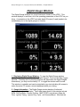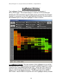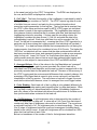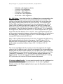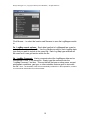
1
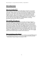
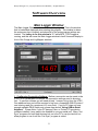
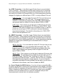
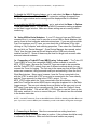
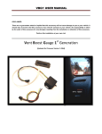
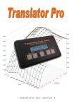
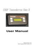
MPS_UTECLogger 3.0 User Manual Last Revised August 2007 MPS_UTECLogger v3.0 | Copyright © 2007 By Jason Mussetter | All Rights Reserved Table Of Contents I. Introduction A. What is TurboXS’s UTEC? B. What can MPS_UTECLogger do? C. Software Requirements II. Software Overview A. Main Logger Window 1. Communication Setup a. UTEC Connection b. Wide Band O2 Meter Connection c. How to Disable the WB-O2 device d. Using USB-to-Serial adapters e. Connecting a TurboXS Tuner WBO2 using “inline mode” 2. Connecting to Devices 3. Recording Raw Logs a. Saving Log Files 4. Dis-Connecting from Devices B. Digital Gauge Window 1. Displaying the Digital Guage Window 2. Gauge Information a. Knock Indicator C. LogMapper Window 1. LogMapper Concept 2. Cell “Hits” 3. Averaged Values 4. Color Shading a. Cell Brightness b. Cell Colors 5. Saving LogMaps a. LogMap Export Options 2 MPS_UTECLogger v3.0 | Copyright © 2007 By Jason Mussetter | All Rights Reserved b. LogMap Comments Appendix I: How to Buy and Register MPS_UTECLogger Appendix II: Software End User Licence Agreement (EULA) 3 MPS_UTECLogger v3.0 | Copyright © 2007 By Jason Mussetter | All Rights Reserved Introduction What is the TurboXS UTEC? When TurboXS released their User Tunable Engine Computer to the market several years ago, it was received with excitement from the car performance community. There weren’t very many (if any) solutions available to the public that gave so much control to the performance and tuning capabilities of the engine’s computer. Not only that, it was one of the few solutions that didn’t require proprietary software only available to professional tuners that sell it. It was this freedom for the average knowledgeable person to be able to custom tune their car’s ECU without the need of special software or licensing agreements that makes the UTEC so powerful. What can MPS_UTECLogger do? MPS_UTECLogger is the most versatile and useful companion software for TurboXS’s UTEC engine management computer there is. MPS_UTECLogger was made with road-tuning in mind from the start, however it can be just as useful for dyno-tuning as well. MPS_UTECLogger has several main functions that make tuning easier, including advanced logging support for tuning sessions, digital gauges that display all the main UTEC parameters in real-time, as well as an advanced real-time log-mapper that uses averaging to give the user a visual display of the logging session in the same format that the UTEC uses for tuning. In addition, the software allows you to add a wide-band O2 meter to the logging session which makes tuning even easier and more accurate. What is required to run this software? A PC running at Windows 98, NT, 2000, or XP. Minimum required RAM depends on operating system, but windows recommended amount should be sufficient. - At least one (1) Serial Com port to connect to UTEC 4 MPS_UTECLogger v3.0 | Copyright © 2007 By Jason Mussetter | All Rights Reserved Software Overview Main Logger Window: The Main Logger Window is the core of the main program. This is the window that is loaded and displayed when starting the program. This window is where the main menu bar is located, and almost all of the main program settings are located. The hotkey to for this window is “L” while MPS_UTECLogger is running, and this will cause the Main Logger window to have focus and display in front of the Guage and LogMapper windows. 1. Configuring Connection Settings: Before a connection can be made to the UTEC or to a Wide Band O2 device, the connection settings need to be setup first. To use this software you will need at least 1 comport to log from the UTEC. One additional com port will be required to log from a compatible WB-O2 meter if one is being used (for a maximum of 2 com ports). If you’re PC does not have enough available DB-9 Serial ports, please see section “Using USB-to-Serial Adapters”. Please Note, if your PC has any Palm, or Pocket PC type device software installed, it may need to be disabled to use your serial port. Many “Hot Sync” programs for hand held devices lock on to the PC’s com port and do not allow program to use it until the “Hot Sync” program is exited. 5 MPS_UTECLogger v3.0 | Copyright © 2007 By Jason Mussetter | All Rights Reserved 1a. UTEC Connection: In the Main Logger Window there is an area labeled UTEC Connection. These settings must be setup correctly prior to connecting. Once these setting are changed, the program will remember them for the next time and will only need to be changed when one of these parameters physically changes, like logging on a different type of UTEC, or using a different Com port. UTEC Com Port – You must select the correct PC Com port that you are physically connecting to the UTEC with. The program supports up to “COM 20” to eliminate any problems with using USB-to-Serial Adapters that typically install at a higher Port than the typical COM2 or COM3. UTEC Type – This is where you set the type of UTEC that you are using. The available options include WRX, STi, Evo8, and 350z UTEC’s. Each version of UTEC made for different cars is somewhat unique, so failure to provide the correct type of UTEC could result in incorrect data being recorded and displayed. The default for this setting is for “WRX UTEC” the first time the application is run. 1b. WBO2 Connection: In the Main Logger Window there is an area labeled WBO2 Connection. These settings must be setup correctly prior to connecting. Once these settings are changed, the program will remember them for the next time and will only need to be changed when one of these parameters physically changes, like logging with a different type of wide-band sensor or using a different Com port. WB-O2 Com Port – You must select the correct PC Com port that you are physically connecting to your compatible wide-band sensor with. The program supports up to “COM 20” to eliminate any problems with using USB-to-Serial Adapters that typically install at a higher Port than the typical COM2 or COM3. WB-O2 Type – This is where you set the type of wide-band O2 sensor that you are using. The available options include the Innovate LM-1 and LC-1, AEM UEGO Meter, TurboXS Tuner, Tech Edge 2.0 meter, PLX Devices and Zeitronix’s wide band meter. Currently, these are the only compatible Wide-band O2 meters that the software supports. If you do not have a compatible Wide-band O2 meter available, and still wish to use the rest of the feature in this software, read “How to disable the WBO2”. 1c. How to Disable the WB-O2 device: If you do not have a compatible WBO2 meter, and still wish to use the rest of the features in this software, you MUST disable the WB-O2 connection settings and connect to just the UTEC for logging. Failure to disable the WB-O2 device if it is missing may cause serious program problems, since the software will try to open the configured serial port and communicate with a device that is not actually connected. 6 MPS_UTECLogger v3.0 | Copyright © 2007 By Jason Mussetter | All Rights Reserved To disable the WB-O2 logging feature - go to, and select the Menu -> Options -> WBO2 Disable. You will see the WB-O2 connection settings dis-appear from the Main Logger window and a message will be displayed that it is disabled. To re-enable the WB-O2 logging feature - go to, and select the Menu -> Options -> WB O2 Enable option. You will see the WB-O2 connection setting re-appear on the Main Logger window. Make sure these setting are set correctly before continuing. 1d. Using USB-to-Serial Adapters: If your PC does not have any DB9 serial connectors on it, you may have to use one or more USB-to-Serial adapters, that can be found at most computer and electronics stores. If you are not sure which Com Port numbers your PC uses, you can check this in Windows XP by rightclicking on “My Computer” and selecting properties. Then select the “Hardware” tab, and click on “Device Manager”. Once Device Manager has opened, select “Ports” from the tree view and this will display all the COM ports currently installed on the PC. Some of these may be used for things such as some older mice and external modems. 1e. Connecting a TurboXS Tuner WBO2 using “inline mode”: The Turbo XS Tuner WBO2 is one of the compatible WBO2 meters available to use with MPS_UTECLogger. Because the TurboXS Tuner was made to be compatible with the TurboXS UTEC natively, there are 2 different methods which you can connect the Tuner for logging. The first way is the same way that all other WBO2 meters are connected, using a second serial port and selecting it from the list of Wide Band devices. Many users, however, have the Tuner connected in-line with the UTEC in which the UTEC’s com port is connected to the Tuner directly, and the Tuner appends it’s data to the UTEC’s output. To use MPS_UTECLogger which the Tuner connected in this inline fashion, simply select the Tuner as the active WBO2 device using the dropdown list on the Main Logger screen. The com port selected does not matter in this case, and you do NOT need 2 com ports as you normally would. Next, from the “Options” menu, select “WBO2 disable”. This will tell MPS_UTECLogger to use the Tuner as the WB meter, and that it is not on a second com port. You should see this reflected in the bottom status bar. NOTE: You MUST select the Tuner as the WBO2 device PRIOR to disabling the Wide Band com port. If you don’t, once the WBO2 port is disabled, you will not be able to change the device type. 2. Connecting to Devices: After the communications setting have been configured properly following the steps in section 1, the software should be ready to connect to the devices. Make sure that the serial cables are properly 7 MPS_UTECLogger v3.0 | Copyright © 2007 By Jason Mussetter | All Rights Reserved connected with all the devices that are being used, and that the devices are powered on prior to clicking on the “CONNECT TO DEVICES” button. If the devices are not powered prior to connecting to them, they may not log correctly, since the commands to initiate logging mode on the devices are sent during the initial connection. You can also connect to devices using the HotKey <spacebar> and this will open the connection. Once the software is connected, you should see verification of this by looking in the Real-time UTEC Log text field on the Main Logger Window. The text field should be continuously updated with log data coming from the UTEC. In addition, if a wide band O2 sensor is being used, you should see the current Air/Fuel Ratio in big red numbers being displayed on the Main Logger Window. At this point the software has correctly connected to the devices and is already analyzing the data coming in. A “Port Open” message will appear in the bottom status bar. NOTE: You may or not see a value displayed in the “Lambda” display depending on which make/model of wide band O2 meter that you are currently using. Currently, only the Innovate LM-1 and LC-1 report the actual Lambda value, using any other wide band O2 meter will result in the Lambda value showing “0” while the Air/Fuel Ratio displays correctly. 3. Recording Raw Logs: MPS_UTECLogger can optionally record raw logs from the UTEC and WBO2 devices if the user wishes to save the logging session to permanent memory for later review. This captures the data from the UTEC to a standard comma delimited text file that is readable with notepad or WordPad. The raw logging column format is the same format that the UTEC outputs under it’s “Logger #1” logging option. All options for recording log files are located near the bottom of the Main Logger Window. If a wide band O2 meter is being used for the logging session, then the Air/Fuel Ratio from the WB-O2 meter will be appended to the end of the normal UTEC log line, in essence, forming an extra column at the end of the line with the appended data. Note that in certain circumstances, like while logging with the TurboXS Tuner (connected on a separate com port) that extra data may also be appended to the normal UTEC log line. In these special cases, the extra info that is being appended is data that the wide band O2 meter (the Tuner in this case) is supplying. Extra data appended may include useful information such as EGT and Knock from the Tuner’s built in EGT and knock sensors. 3a. Saving Log Files: If you want to save the log file to disk, you must follow the directions below for Saving Log Files prior to making a log run in the car. To have the software log to disk follow these steps: 1) click on “BROWSE” which will open up a file save dialog box. Navigate to the directory that you wish to save the log 8 MPS_UTECLogger v3.0 | Copyright © 2007 By Jason Mussetter | All Rights Reserved file to and give the log file a name and click “SAVE”. You will now see the directory and file name that the log will be saved under. It is recommended that you save the file with a .CSV extension so that spreadsheet programs can properly read/interpret the columns in the file. Alternatively, you can use the Hotkey <F3> to have MPS_UTECLogger create a new filename based on the current date and time in the current directory specified. This is handy for creating multiple logs during a logging session, as you don’t have to use the mouse to navigate while driving. 2) To start recording the log, click on “START LOG”. This will create the file that you specified and start recording all the data that is displayed in the “Real-time UTEC Log” text window. If you specified a name that already exists, the existing file will be over-written without warning. Any previous log data contained in the file will be lost. To record multiple logging sessions, specify a new filename prior to starting the log again. You can also use the Hotkey <F1> to start recording (it is suggested to use the Hotkey <F3> prior to this to make sure the log has a unique name. 3) To stop recording the log, click on “STOP LOG”. This will stop the recording and close the file. The file is ready to be viewed by any text editor or spreadsheet program. You can also stop the logging process by using the Hotkey<F2>. 4. Dis-connecting from Devices: After all logging sessions are completed, and the logging has been stopped, click on the “Dis-connect from Devices” button. This will cause the software to stop all communications will both the UTEC and any wide band O2 meter connected. All logs files will be closed and the software will release the PC’s serial ports. This should be done prior to shutting down the software, or prior to attempting to connect to the UTEC with HyperTerminal. You will see a “Port Closed” message in the bottom status bar. You MUST disconnect from devices PRIOR to trying to use “DirectLink” or HyperTerminal to connect to the UTEC for editing. You may also use the Hotkey “<escape>” to disconnect from the devices. 9 MPS_UTECLogger v3.0 | Copyright © 2007 By Jason Mussetter | All Rights Reserved Digital Gauge Window: The Digital Gauge Window is a virtual instrument cluster for the UTEC. This window displays, in real-time, all of the operating parameters of the UTEC as you drive. A connection to the UTEC and wide-band O2 meter (if used) needs to be established prior to the digital gauges to function. 1. Displaying Digital Gauge Window: To view the Digital Gauge window, check the selection box labeled “View Digital Gauges”, found on the Main Logger Window. Checking and un-checking this box will open/close the Digital Gauges. Alternatively, you may use the hotkey “G” to toggle the window on/off as well. This window is resizable and can be stretched to any size including full screen to make the entire PC screen a virtual dashboard while your driving. 2. Gauge Information: The Digital Gauge window displays 8 individual readings plus a knock indicator. The 8 data types shown in this window include: RPM, Air/Fuel Ratio, Throttle Position, MAP (UTEC Load column), Mass Air Flow, Ignition Timing, Injector Duty Cycle, and Vacuum/Boost. Note that the 10 MPS_UTECLogger v3.0 | Copyright © 2007 By Jason Mussetter | All Rights Reserved Air/Fuel Ratio will only be displayed if an optional Wide-band O2 meter is being used. 2a. Knock Indicator: The “Knock indicator” is not visible on the Digital Gauge window unless a knock event is actually detected. If a knock event is detected, then a red “Knock Warning!!!” MIL will illuminate at the top of this window just above the 8 gauge readouts. It will blink for a brief period of time to warn you that a knock event occurred. In addition, a sound will also be emitted from the PC speakers to give an audible knock warning for easier indication while driving. 11 MPS_UTECLogger v3.0 | Copyright © 2007 By Jason Mussetter | All Rights Reserved LogMapper Window: The LogMapper Window is one of the most powerful components of MPS_UTECLogger. This window displays, in real-time, a 2D formatted grid detailing all of the information from the digital gauges composited and averaged together. A connection to the UTEC and wide-band O2 meter (if used) needs to be established prior to using the LogMapper in order to function. 1. LogMapper Concept: The main concept of the LogMapper is to put all the data gathered from a logging session into a easily readable format that is similar in layout to the Tuning Maps used by the UTEC. Just as the UTEC uses a 2d map for Fueling, Timing, and Boost, the LogMapper uses the same concept to show you ALL of the logged information. The 2D map is laid out in a RPM x MAP format. Values located in a specific cell of the LogMapper directly correlate 12 MPS_UTECLogger v3.0 | Copyright © 2007 By Jason Mussetter | All Rights Reserved to the same load cell on the UTEC Tuning tables. The RPM’s are displayed as the row, and the MAP is displayed as columns. 2. Cell “Hits”: The basic functionality of the LogMapper is calculated by what’s MPS_UTECLogger considers a “Cell Hit”. The UTEC outputs log data at a rate of multiple lines per second, and each log line contains information about numerous engine parameters for that log-line. The log line that is received from the UTEC is then taken and broken apart by MPS_UTECLogger into individual data values for each of the engine parameters. The LogMapper then analyzes this instance of data to determine that it contains valid data, and that meets the LogMapping criteria for recording. If it does meet the recording criteria, the LogMapper considers this data as one (1) Cell Hit, and adds the data to the corresponding Load cell. Each time valid data for a cell is recorded, the “Hit Count” for that cell is incremented by 1, meaning that if the UTEC logs data for a particular cell 4 times during the Logging session, that individual cell has had 4 “Hit Counts”. If no data has been received that corresponds will a cell during the logging session, then that cell is considered to have 0 Hit Counts. The higher the “Hit Count” an individual cell has, means that the data contained within the cell has been recorded more times, and averaged together to make a more accurate value for that cell. Lower “Hit Counts” for a cell means that data for that cell (while possibly accurate) has not had as much data gathered while logging and therefore is more subject to inaccuracies of the UTEC and WBO2 devices. 3. Averaged Values: Most of the values in the Log Map tables are “averaged” values. Meaning that for each log event recorded, the current load cell is calculated from RPM and Map data, and the new log data is averaged with to the previously recorded data for that particular load cell. Because of the accuracy of the UTEC Logging and the environmental differences that constantly change, this averaging of the logged data is meant to give a more real-world, and accurate, interpretation of the log session. The more times a load cell is logged, the more accurate the data should become, since it is averaged from more logged values. 4. Color Shading: Each load cell of the Log Map is color shaded (differently for each data type) to make reading and interpreting the Log Map data easier. While the Log Map is really a 2-dimensional table of values, the shading (brightness and color values) of the individual cells allows the vehicle tuner to visualize more than just the data values contained in the load cell. 4a. Cell Brightness: A cells brightness value is determined by the number of “Hits” for a particular Log Map cell. A value with a 0 Hit Count (one that doesn’t contain any data) has no brightness value and is colored black. The more times a particular load cell is “hit”, it’s brightness value is raised accordingly. There are five (6) steps of brightness levels that a cell can be assigned (including black), based on the cells hit count. A load cell’s brightness will be considered at 100% when that load cell has at least 6 hits. Below is a breakdown of the number of hits for the brightness intensities: 13 MPS_UTECLogger v3.0 | Copyright © 2007 By Jason Mussetter | All Rights Reserved - 0 Cell Hits = 0% brightness (black) 1 Cell Hit = 20% brightness 2 Cell Hits = 40% brightness 3 Cell Hits = 60% brightness 4-5 Cell Hits = 80% brightness >6 Cell Hits = 100% brightness 4b. Cell Colors: Each data type that is LogMapped has a corresponding color range for the cells based on the current data contained in the load cell. The coloring of the load cells is determined from the data for the current data type that is being viewed rather than the hit count of the cell. For instance if the Air/Fuel Ratio Log Map is being viewed, the colors will represent the Air/Fuel value for that cell within the valid color range for the Air/Fuel Log Map type. Depending on the Log Map data type that is being view, different color ranges are assigned. Using the previous example, an AFR value of 16:1 or leaner will be assigned red, while an AFR value of 12.5:1 will be assigned the color yellow. If the AFR value falls between 12.5:1 and 16:1, then a graduated (mixed) color will be assigned somewhere between yellow and red depending on it’s position in the value range. So for an AFR value of 14.25:1, the color assigned will be orange (50% yellow mixed with 50% red). Many of the Log Map data types have 3 set colors, for instance the Air/Fuel Log Map mentioned previously works in this manner. An AFR value of 10:1 is assigned green, so depending on what the current A/F value in a cell is, can have a range somewhere between Green=10.0:1 Yellow=12.5:1 Red=16:1. The tri-color Log Maps make if very easy to see how progressive the logged values in the Log Map are, and to spot abrupt changes in the tuning parameters. Keeping with the Air/Fuel Ratio example, you can quickly see if your running rich (shown by green) or lean (shown by orange/red), or how close the tune is to the “power AFR” (considered ~12.5:1 for most gasoline engines) because it will appear yellow. You can also see the transitions between Stoich (14.7 cruising AFR) and rich as the load and RPM are increased/decreased. 5. Saving LogMap Results: You may save the results from the LogMapper to a .cvs (comma delimited spreadsheet) document. On the main LogMapper Window, click on the “Save LogMap” button to open the Save Options window shown below. 14 MPS_UTECLogger v3.0 | Copyright © 2007 By Jason Mussetter | All Rights Reserved Click Browse… to select the location and filename to save the LogMapper results to. 5a. LogMap export options: Each data type that is LogMapped has a can be included in the exported .cvs file. Use the checkboxes next to each LogMap data type that you want to include in the saved file. Each Log Map type selected will be saved as it’s own grid section within the file. 5b. LogMap Comment: User’s comments about the LogMapper data can be included as a “note” in the saved file. Simply type the comments into the “LogMap Comment:” text box. This can include the tuner or shop name, current atmospheric conditions, gas type, or other variables that are good to store with the file. Note: The time/date of the file is automatically included for in the exported file, so there is not a need to include this info in the comment. 15 MPS_UTECLogger v3.0 | Copyright © 2007 By Jason Mussetter | All Rights Reserved Appendix I: How to Buy and Register the Software To Buy and Register the software is several step process, but is easily done by following these simple steps: 1) Download and Install the Trial Version of MPS_UTECLogger on the PC that you will use for logging. The main download page can be found at http://mpsav.com/MPSUTECLogger/MPS_UTECLogger_Download.htm 2) Run the Trial Version of MPS_UTECLogger and from the Main window, select “Help” from the menu bar and select “Register Program”. This will open up the Registration Window. Make note of the “Registration Key Index” number shown in the middle of the window. This number is important as it determines what set of product you receive after buying and registration. 3) Goto: http://mpsav.com\MPSUTECLogger\Registration\Resigration_Form.htm and complete the entire registration form. The contact info here will be used to send your product key. Make sure you include the correct “Registration Key Index” retrieved in step2. This will determine the exact set of keys that your installation requires. Submit the Registration Form. 4) After submitting the Registration Form, the next page will tell you if you were successful. If so, click on the “Buy Now” button to be taken to Paypal where your payment transaction will be completed. 5) After completing the payment, the payment and Registration will be verified and your registration keys will be sent to you. Enter these keys into the correct fields in the Registration Window of MPS_UTECLogger. 16 MPS_UTECLogger v3.0 | Copyright © 2007 By Jason Mussetter | All Rights Reserved Appendix II: MPS_UTECLogger Software End User Licence Agreement (EULA) Please read the following terms and conditions carefully before using this SOFTWARE PRODUCT. Your use, distribution or installation of this copy of "MPS_UTECLogger" indicates your acceptance of this License. SOFTWARE PRODUCT here means Software, image files, all accompanying files, data and materials received with your order of "MPS_UTECLogger". If you do not agree to any of the terms of this License, then do not install, distribute or use the SOFTWARE PRODUCT. If you have purchased a single copy from Mussetter Programming Services or an authorized distributor, reseller or any retail channel, you may return it unused, within thirty (30) days after purchase, for a refund of your payment less any incidental charges. The 30-day warrantee is applicable only to products bought within US. Products downloaded to or shipped out of US are strictly non-refundable. Warrantee covers defects in the software, which prevents successfully installing the software in the buyer's PC. Warrantee does not cover fitness of purpose, not meeting of expectations or needs in the mind of the buyer. This SOFTWARE PRODUCT is for personal use only and may be installed and used by on only one computer. Its component parts may not be separated for use on more than one computer. SOFTWARE PRODUCT may be accessed through a network only after obtaining a site license. All components accompanying the software are copyrighted by Mussetter Programming Services and may not be taken apart, modified, used or published with other software or means except with the SOFTWARE PRODUCT software and may not be distributed or copied in any manner. This SOFTWARE PRODUCT, all accompanying files, data and materials, are distributed "AS IS" and with no warranties of any kind, whether express or implied. The user must assume all risk of using the program. This disclaimer of warranty constitutes an essential part of the agreement. Any liability of Mussetter Programming Services will be limited exclusively to refund of purchase price. In addition, in no event shall Mussetter Programming Services, or its principals, shareholders, officers, employees, affiliates, contractors, subsidiaries, or parent organizations, be liable for any incidental, consequential, punitive or any other damages whatsoever relating to the use of SOFTWARE PRODUCT. In addition, in no event does Mussetter Programming Services authorize you to use this SOFTWARE PRODUCT in applications or systems where SOFTWARE PRODUCT 's failure to perform can reasonably be expected to result in a physical injury, or in loss of life. Any such use by you is entirely at your own risk, and you agree to hold Mussetter Programming Services harmless from any claims or losses relating to such unauthorized use. This Agreement constitutes the entire statement of the Agreement between the parties on the subject matter, and merges and supersedes all other or prior understandings, purchase orders, agreements and arrangements. This Agreement shall be governed by the laws of US OR STATE. Mussetter Programming Services the owner of the copyright of this SOFTWARE PRODUCT, all of its derivatives, title and accompanying materials are the exclusive property of Mussetter Programming Services. All rights of any kind, which are not expressly granted in this License, are 17 MPS_UTECLogger v3.0 | Copyright © 2007 By Jason Mussetter | All Rights Reserved entirely and exclusively reserved to and by Mussetter Programming Services. You may not rent, lease, transfer, modify, translate, reverse engineer, de-compile, disassemble or create derivative works based on this SOFTWARE PRODUCT. This SOFTWARE PRODUCT and all services provided may be used for lawful purposes only. Transmission, storage, or presentation of any information, data or material in violation of any US, State or City law is strictly prohibited. This includes, but is not limited to: copyrighted material, material we judge to be threatening or obscene, or material protected by trade secret and other statute. You agree to indemnify and hold Mussetter Programming Services harmless from any claims resulting from the use of this SOFTWARE PRODUCT, which may damage any other party. 18