1
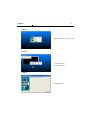
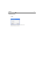
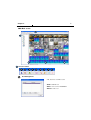
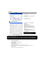
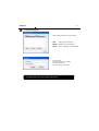
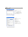
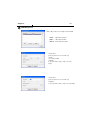
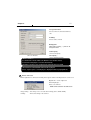
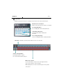
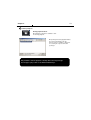
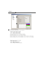
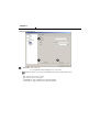
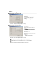
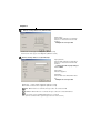
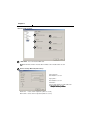
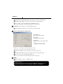
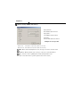
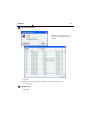
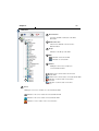
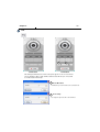
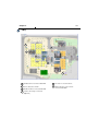
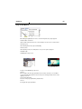
Rev.1
'9577 CMS User Manual
CMS(Central Monitoring System)
Chapter I
2
System Requirements
OS
CPU
Win 2000 / Win XP / Win Vista
INTEL P-4 2.4Ghz or over(recommends Dual-core,over )
Main Memory
512MByte or over (recommends 1Gbyte,over)
Video Memory
64M over supports RGB (recommends 128Mbyte over)
Resolution
1024*768 over
Lan Card
10/100 Supporting card
Protocol
TCP/IP
Function and Specification
DVR
Max connectable no of DVR
Max Display frame
Various multi-window
Remote monitoring
XTT Series
Theoretically, it connects max 64 cameras. But realistically,
it needs to be connected considering below max display
frame (5~10 units)
420fps. A bit variable according to a kind of DVR and
network status
1,4,9,16,36,64,Full Screen
Connectable the other TT series at the same time
Remote Set-up
Available to set up main menu of DVR
Remote backup
Available to backup of recorded data
Local playback
Available to playback of backup file
E-MAP
Linked with E-MAP, available to manage DVR
Motion Pop-up
Remote monitoring & EMAP window support motion popup
Useful additional function
Print, Image saving, AVI saving etc, PTZ Dual Monitor is
supported
Chapter I
3
Program Installation
1
Displaying program version, produced date
- Lock version
Step 1
- Trail version
- Free version
2
Install button ‘click’
Chapter I
4
Step 2
<displaying Installation progress status>
Step 3
<Codec installation>
Certainly ‘click’ YES
3
Step 4
<installation ends>
Chapter I
Program execution
Login
When program is first executed, puts in ID,Password
Default – ID: admin , Password: 1.
5
Chapter II
6
CMS Main screen
1
7
2
3
4
1
5
6
Function button
1
1
2
3
4
5
6
7
8
9
User Management
Add, edit, delete of CMS account.
Add : add CMS user
Edit : revise user ID, PASSWORD
Delete:
: delete user
Chapter II
7
User name :
Type the user name authorized in DVR
Password:
Type the password authorized in DVR
User explain:
Shows the user information
<Use management add/modify >
2
Option management
Language : To choose program’
language.
Video output : ATI
YUV mode : According to your PC
graphic card ability, the support can be
decided. This mode shows faster, clear
ability of image transmission than RGB
mode.
RGB mode : nVidia
It is widely compatible with most graphic
cards, and select this when TUV mode
is not supported.
Above setting value will apply after
restarting of the program.
<Option management>
<Recommended Graphic Card>
ATI series : Radeon7000 series (More than 32M, more than 64M recommendable), RADEON series…
NVIDIA series : More than M64 series (Min over 32M, more than 64M recommendable), GEFORCE series
Etc :VGA card to support YUV mode… , Recommended 2 times memory when dual monitor is used.
Space for saving data
Sets ups basic path of AVI file to save
AVI Saving time
Sets up saving time of AVI file from CMS.
Transmission Speed
High Speed : System sends off images at high speed possible.
Low Speed : System sends off image at normal speed in consideration of stability.
Event Sound
Set ups sound file (*.wav), when the event occurs.
Chapter II
3
8
Group management
Add, modify and delete a group in DVR
Add…
: Add a group information
Modify...: Modify a group information
Delete
: Delete existing group information.
Group name :
Specify a group name in DVR
Group information:
Specify a group information
To register DVR , you need to register a group first.
Chapter II
4
9
DVR Management
Add /modify/Delete DVR connection in
the CMS
Add… : Enter IP address and user
aut h ent i c at i o n t o connect DVR
Edit... : Modify IP address and user
authentication of the existing list
Delete : Delete existing use.
DVR name:
Specify a name that you can easily
identify.
Group :
Select the DVR group
Address :
IP address to connect
(type IP or DDNS Host Name)
Service port :
Set service port same to DVR’s one
User name:
Type user name of DVR authorized
Password : Type password to DVR authorized .
Connect all : connect all when it connects
Chapter II
5
10
VIEW Management
Adds, edits, deletes Live/ E-map showed in CMS
Add… : add View information
Edit... : edit View information
Delete : delete View information
View name :
put in any name for user to know easy
kinds :
select LIVE or MAP
Map file :
In case the View is map, select to be used
image
View name :
put in any name for user to know easy
Map file :
In case the View is map, select to be used image
Chapter II
11
Search
6
1
4
12
5
6
10
7
8
9
2
11
3
1
Video playback screen
Camera
name
Green border line :
displays selected camera.
Recorded
date/time
2
SECTION
Select “SECTION”
Chapter II
3
12
Move and Event search
Move button : move to selected time.
Event search button : popup event search window
Shows start and end time of recorded
data
Moves to the time to search and press
OK button
<Move Window>
Select time to event search
Select events in detail
Select camera to search
Start event search
Click “NEXT” button to see next
event data
Shows current searched event lists
Hotkey : Play searched event
Next : Search next event.
<Event search window>
to see next event search, click
“NEXT” button
Pls make sure to select LOG of the system. If not event lists are not searched
Chapter II
4
13
Connection information and button
Shows DVR name, IP address and connection status
Backup play button
Connect / Disconnect button:
Button to connect to other DVR in the saved list
When many DVRs are registered in DVR list,
Each DVR can be remotely searched without
Closing remote program
Linked lists cant not be edited while search.
<Connection list window>
5 Playback button
Playback / Pause
Previous frame : Play
previous frames reverse
direction
Next frame : Play next
frames forward direction
Starting :
Move to starting of record
data
Fast rewind : fast
reverse play every 1
minute
End : Move to end of
record data
Fast forward : Fast
play every 1 minute
Speed control bar
Chapter II
6
14
Screen division button
Screen division button
7
AUDIO play
It is the function that control audio at REMOTE Live
Audio is only able to play on one full screen
Sound volume control gauge
Mute button :
Stops audio transmission
8
Image control button
Brightnes
s
Contrast
Brightness adjustment button :
Adjusts brightness of playing images
Blurrng
Sharpnes
s
Contrast adjustment button :
Adjusts contrast of playing images
Blurring adjustment button :
Adjusts blurring of playing images
Sharpness adjustment button :
Adjusts sharpness of playing images
Reset button :
Zoom button :
Zoom the selected part
Initializes adjusted image to original image
Chapter II
9
15
Saving button
Backup :
Backup
Backups searched image as compressed
Print
image file
Image save
AVI save
print :
Prints searched image
Image save :
Saves searched image as image file
(saves JPEG or BMP)
AVI save :
Saves searched images as AVI file
Storage information :
Select start and end time to backup
image
Backup camera :
Select camera to backup
Including :
Selects audio and event to include
Backup path :
Selects path to backup
Total capacity :
shows total capacity of the device
Used capacity :
Shows used capacity
Left capacity :
Shows remaining capacity
<Backup window>
Chapter II
16
Preview :
Preview of the images to print,
Which is printed with various information
written on the bottom of the image
<Print preview window>
Image format
JPG format :
Definition has a little loss due to loss
compression method, but archiving size
is small
BMP format :
<Image save window>
Archiving size is a bit big due to no
compression, but it can be saved as
higher definition that JPG
Saving path : selects path to backup, “…”path can be changed to button
Chapter II
17
Storage information
Selects camera no and start/end time to
save
Including :
Selects audio to include
Backup path :
sel ec t s p at h t o b ac k up , “ … ” p at h c an b e
c h ang ed t o b ut t o n
Total Capacity :
shows total capacity
<AVI save window>
<What is AVI file?>
Left capacity :
shows remaining capacity.
It is Audio/Video format of Microsoft Windows. If it is double clicked,
browser like media player is executed automatically
and video is shown, as it is compressed too much file size is not small
<How to find recorded date/time when AVI file is palyed>
Check “caption option” of media player to display time/date of playing AVI file.
1 0
Mouse click action
When right button is clicked, the following menu appears and the following functions can be used
Original Size : shows original size
AVI Saving Begins.. :
Start to save AVI files
Audio can be saved on one full screen
Image Saving.. : Save image of the selected channel image (Saves JPEG or BMP)
Printing..
: Print current image of the channel
Chapter II
1 1
18
Time Table
Available to play back the data on selecting the time, minutes of the date, month and year.
Month/Year selection button :
Button used to got to previous month or next month.
Recording Date (Blue) :
The recording date, which is indicated in blue.
Current Date (Blue block) :
The current date, which is indicated in
blue block.
No recording date (black) :
The no recording date, which is indicated in black.
Time Table : It indicates as 24 hour units, which consists of one hour unit.
Camera Selecting Button:
If pushing the button on pause,
the selected channel will be going on.
Minute Select Pointer :
To select the minute, select the hour on the right & left side
and select the channel on the up & down.
While playing back, select the search time by the mouse pointer
on the pause.
Chapter II
1 2
19
Backup Playback
Backup playback button :
On clicking the left button, available to take
the backup playback.
On pushing the backup playback button,
the explorer window like left side
appears and it is available to play back
on selecting the requested file and
opening it.
Only available to take the playback of backup data as the image file type.
The AVI type is just possible on the Windows Media Player.
Chapter II
Remote Set Up <Camera>
1
2
3
4
1
No : Item to select camera No
To set up all the camera equally, Choose “select all”
Enable : Selection item to use camera, Removing the check stops using that channel.
2
Title : Item to revise/type the camera name.
Security : When checked, It displays ‘Hidden’ on monitor. (though it keeps recording)
3
Link PTZ : Sets up PTZ camera.
PTZ address: Item to assign PAN TILT address per camera.
Name :Item to check PTZ Camera’s model name.
ID : Item to select PTZ address per camera.
Port bit rate : Item to select the PTZ’s port bit rate.
Data bit :Item to select data bit.
Stop bit : Item to select Stop bit.
Parity : Item to select Parity.
4
Audio : Item to select which audio channel to be used among total 4 audio inputs.
Chapter II
Remote Setup <Alarm>
1
1
No : “”
Enable : Title : Item to type Alarm’s name.
Type : Item to select Alarm’s type.
- Normal Open : Type of alarm open in general situation.
- Normal Close : Chapter II
Remote Set Up <Record>
1
2
1
No : Item to select Camera No.
“”
.
Resolution : Item to change the resolution.
- NTSC : 720X480, 720X240, 360X240
- PAL : 720X576, 720X288, 360X288
Normal Record Frame :Item to select normal record frame.
Normal Record Quality : Item to select normal record quality.
Event Record Frame :Item to select Event (Motion + Sensor + Video Loss) record speed.
Event Record Quality : Item to select Event (Motion + Sensor + Video Loss) record quality.
Schedule : Item to select record schedule.
- Normal : Always Record
- Event : Motion, Sensor, Video Loss
- N + E : Always + Event Record
- Clear : Delete the current record schedule.
Chapter II
2
Remote Set Up <Record (Timetable)>
1. Select the
Record Mode
2.Select Day/Time
< Schedule of Record>
It is the list of selection in which schedule to
use in operating the relevant camera channel.
First select the item you need among
Normal time, Event and Normal time + Event.
Then drag mouse from the wanted position
on time line.
To edit schedule record,
you need to set record as schedule mode.
Chapter II
Remote Set Up <Record Policy>
1
1
Record Policy: Item to select record policy
Overwrite : When HDD capacity is almost consumed, It erases old data and record new.
Single Record : To stop recording on 100% of HDD capacity.
Chapter II
Remote Set Up <Motion>
1
2
3
1
4
Camera No : Item to select Camera No.
“”
Enable : S Sensitivity : Adjusts the sensitivity in motion detection.
There are 5 steps and as the number increase, it gets more sensitive.
2
Area : Item to select motion area.
Area is selected when drag the mouse on the
image.
<Set Up Area Tool>
Area Draw
button
Area Clear
Button
Chapter II
3
Remote Set Up <Motion (Link Record)>
Link Camera :
Selects which channel to record when
motion is detected on the relevant
channel.
Multiple selection possible
Pre Record : Sets pre-event recording time. (Max 5 second)
Post Record : Sets post-event recording time. (Max 60 second)
4
Remote Set Up <Motion (Link Action)>
Popup Camera :
Selects which channel to Popup when
motion is detected on the relevant
channel.
It works when the Popup setting is
‘Yes’ on DVR.
Popup Time :
Sets Popup time
Link Alarm :
Select Alarm to be linked when motion
Is detected.
Multiple selection possible
Alarm Time : Sets Alarm output time. (Max 30 second)
Buzzer Time : Sets buzzer output time in DVR. (Max 30 second)
Mail : When motion is detected, the log is sent to the selected e-mail.
Call Back : When motion is detected, the log is sent to the selected IP address.
Log : Item to save Log writing when motion detected.
(It is not recorded on the system Log but used for event search.)
Motion detection function is a mode to detect in accordance with the amount of color
Changes of image. So, please be careful that DVR keeps recording as continuous
motion when the image of camera is blinking caused by light problem or camera
Auto Iris problem.
Chapter II
Remote Set Up <Sensor>
1
2
1
3
Sensor No : Sets sensor No.
To set up all the camera equally, Choose “select all”
.
Enable : Selects to use sensor, Removing the check stop using relevant sensor.
Title : Item to select sensor’s name.
Type : Item to select sensor type.
- Normal Open : Type of Alarm open in general situation.
- Normal Close : Type of Alarm close in general situation.
Chapter II
2
Remote Set Up <Sensor (Link Record)>
Link Camera :
Selects which channel to record when
sensor is detected on the relevant
channel.
Multiple selection possible
Pre Record : Sets up pre recording time. (Max 5 second)
Post Record : Sets up post recording time. (Max 60 second)
3
Remote Set Up <Sensor (Link Action)>
Popup Camera :
! ! .
! " # ! $ % % # & # ‘' # ’ ( ) .
Popup Time :
.
Link Alarm :
" ! ! ! * % # % # # Alarm Time : Selects Alarm output time. (Max 30 second)
Buzzer Time : Selects buzzer output time. (Max 30 second)
Mail : When sensor is detected, the log is sent to the selected e-mail.
Call Back : When sensor is detected, the log is sent to the selected IP address
Log : Item to save Log writing when sensor detected
(It is not recorded on the system Log but used for event search.)
Chapter II
Remote Set Up <Video Loss>
1
2
1
3
Camera No : Item to select camera No.
To set up all the camera equally, Choose “select all”
Enable : Selects to use Video Loss.
Chapter II
2
Remote Set Up <Video Loss( Link Record)>
Link Camera :
Selects which channel to record when
video loss is detected on the relevant
channel.
Multiple selection possible
Pre Record : Sets up pre recording time. (Max 5 second)
Post Record : Sets up post recording time. (Max 60 second)
3
Remote Set Up <Video Loss (Link Action)>
Popup Camera :
Selects which channel to Popup when
video loss is detected on the relevant
channel.
It works when the Popup setting is
‘Yes’ on DVR.
Popup Time :
Selects Popup time.
Link Alarm :
Selects Alarm to be linked when video
loss.
Multiple selection possible
Alarm Time : Selects Alarm output time (Max 30 second)
Buzzer Time :Selects buzzer output time (Max 60 second)
Mail : When video loss occurred, the log is sent to the selected e-mail
Call Back : When video loss occurred, the log is sent to the selected IP address.
Log : Item to save Log writing when video loss occurred.
(It is not recorded on the system Log but used for event search.)
Chapter II
Remote Set Up <System>
1
3
5
1
2
4
6
DISK FULL : List for all installed HDD disks.
Disk Full Notice Enable : Activate Disk Full Notice when installed disks are full.
2
Remote Set Up <Disk Full (Link Action)>
Popup Camera :
Not available as of now
Popup Time :
Not available as of now
Link Alarm :
Selects which Alarm to be linked when all
installed HDD disks are full.
* % # % # # Alarm Time : Selects Alarm output time. (Max 30 second)
Buzzer Time : Selects buzzer output time (Max 30 second)
Chapter II
Mail : When all installed HDD disks are full, the log is sent to the selected e-mail
Call Back : When HDDs are full, the log is sent to the selected IP address.
Log : Selects to save Log writing when installed HDDs are full.
(It is not recorded on the system Log, but used for event search.)
3
Disk Error : Shows data error on all of the HDDs installed.
Enable Disk Error : When there is a disk error, it is linked to action.
4
Remote Set Up <Disk Error (Disk Action)>
Popup Camera :
Not available at this moment
Popup Time :
Not available at this moment
Link Alarm :
Selects Alarm to be linked when HDD
error.
Multiple selection possible
# $ % & ' ( ! )
* + + # " + + $ % & ' ( ! )
Mail : When HDD error occurs, the log is sent to the selected e-mail
Call Back : When HDD error occurs, the log is sent to the selected IP address.
Log : Selects to save Log writing when HDD error.
(It is not recorded on the system Log but used for event search.)
5
SMART
Enable SMART : Select to use SMART feature.
SMART Function??
It checks the physical errors and observes the HDD disk continuously such as
Temperature, I/O device errors and general conditions of the HDD disk.
Chapter II
6
Remote Set Up <SMART (Link Action)>
Popup Camera :
Not available at this moment
Popup Time :
Not available at this moment
Link Alarm :
Selects which alarm to be linked
Multiple selection possible
# $ % & ' ( ! )
* + + # * + + $ % & ' ( ! )
Mail : When smart related problem occurs, the log is sent to the selected e-mail.
Call Back : When problem occurs, the log is sent to the selected IP address.
Log : Selects to save Log writing when smart related problem occurs
(It is not recorded on the system Log but used for event search.)
Chapter II
8
34
Program Information
Available to run the Log Viewer of
the version and updated Information
on CMS.
Log Viewer
By CMS, it makes the log of time, IP address, connecting port and status on
connecting system.
9
Program Exit
It exits CMS.
Chapter II
2
35
DVR Tree
1
2
1
All Connection
It connects all DVRs nominated on the DVR
information.
3
4
2
5
All Disconnection
It disconnects all DVRs connected on the
DVR information.
3
Group
Indication of the Group of the DVR
4
DVR
Indication of disconnect DVR
Indication of connect DVR
5
Camera
Making the camera icons enabled, on
connected with the DVR.
Indication of the camera status disconnected
with the DVR
Indication of the camera status connected with the DVR
6
6
Indication of camera status on the motion
detection
Indication of camera status on the video
loss
Sensor
Making the sensor icons enabled, on connected with the DVR
Indication of the sensor status disconnected with the DVR
Indication of the sensor status connected with the DVR
Indication of sensor status on the sensor detection
Chapter II
36
DVR Tree
1
D r a g &
D r o p
2
D r a g &
D r o p
+ After connection, the icon which has connected DVR would drag & drop to the Live
display properly, it’ll be show a display.
, Also the display in the Live display moves to another position, it’ll be show a display
that designated position.
Chapter II
3
37
Main Screen
1
Live Screen
1
3
2
4
1
Channel name
2
Recording Status
3
DVR name
4
Current time
Pop-up menu on clicking the right button of mouse,
•Stop : Temporary stops the current image of live view.
•Close: On the live view, it deletes the live channel.
•Image storage : Storage of the current live view as the
image.
•Print: Printing out the current live view.
•AVI : Storage of the current live view as AVI file.
<AVI Storage>
On storing AVI, it stops the archive automatically by the setup time
on the option, without any stop order.
4
Screen Splitting Button
It supports up to 64 screen splitting.
• Full Screen Button
It shows the view of live screen. .
5
Screen Movement Button
On the splitting live screen, it moves the next or the before.
Chapter II
6
38
PTZ
1
PTZ Disabled
2
PTZ Enabled
On clicking the PTZ button, the PTZ control panel appears. If the selected camera
has the disabled setting of PTZ, it will be disabled status like No.1pic. If not, it will
be enabled status like No.2pic.
1
Preset Movement
It makes the preset moved to the selected area.
2
Preset Setup
It sets up the preset to the selected area.
Chapter II
7
39
E-Map
1
4
2
3
5
6
1
Enabled camera connected with DVR
2
3
Sensor Detection of DVR
4
5
Disabled camera connected with DVR
6
It makes other maps connected
(Map Link)
Live view of selected camera
Motion detection of the camera
connected with DVR
Chapter II
40
Usage of Dual Monitor
On clicking the right button of mouse on the E-map tab, the pop-up appears.
Dual monitor movement
On the dual monitor function, the selected map is moved to the second monitor.
Event pop-up
On detecting motion, Pop-up automatically.
Event sound
On detecting event, the sound (that is set up on the option) happens.
Initialize map
Initializing the map screen.
Fixed Screen
Released Screen
Pop-up screen Window pop-up menu
Fixed
On selecting it, the live pop-up window is fixed. Unless fixed, the screen will be
closed automatically any times later. If fixed, the lock image will be shown on the
right top of screen.
Zoom-in double times.
Zoom-in of live pop-up window by double-times.
Close
Closing the live pop-up window.