1
Version 1.0
Produced in Mar. 1999
R
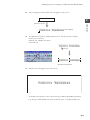
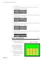
Control Terminal
Model name
Screen edit software
ZM-71SE
User's Manual/Tutorial
Thank you for purchasing the drawing/editing software of ZM series for Windows95/NT (ZM-71SE).
This manual leads you to understand the outline and the functions of the drawing/editing software of ZM
series for Windows 95/NT (ZM-71SE) and to master it effectly, by making each example of each chapter.
Read this manual thoroughly to completely familiarize yourself with the operation according to the examples.
Keep this manual for future reference. We are confident that this manual will be helpful whenever you
encounter a problem.
Note
•
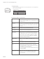
In this manual, ZM-70 and ZM-80 are expressed as follows.
Expression in this manual
Module name
ZM-70
ZM-41L, ZM-70D, ZM-70T, ZM-70L
ZM-80
ZM-42D/L, ZM-52D, ZM-72D/T, ZM-82D/T/TV
Note
•
•
•
•
This module is made in accordance with Japanese domestic specifications. Its guarantee clauses
are described in a separate guarantee card (packed together with the module). When this module
is used outside Japan, these guarantee clauses are not applicable. In addition, the guarantee
should be understood as a guarantee of the delivered product as a single unit and every other
damages or losses due to damage or malfunction of the product will not be included in this guarantee.
Should you have any questions and inquiries, please feel free to contact our dealers.
The whole or partial photocopy of this booklet is prohibited.
Contents of this booklet may be revised for improvement without notice.
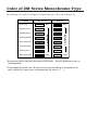
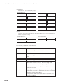
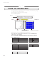
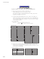
Color of ZM Series Monochrome Type
The following is the color list of ZM Series monochrome types. Refer when editing a file.
Editing
Black (Gray)
ZM70L/41L
White
ZM-42L
Black
Blue (Navy bule)
Red (Mahogany)
8-gradation
Green (Pine green)
8-gradation
Magenta (Maroon)
Blue
White
Cyan (Slate blue)
Yellow (Camel)
White (Silver-color)
*8-gradation colors may be flickering on ZM Series. Using 2-gradation colors is
recommended.
*If the editing file which has 16 colors on the screen editing is changed into ‘8color’ editing file, each color is changed into the color of ( ).
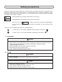
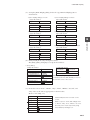
Safety precautions
Read this manual and attached documents carefully before installation, operation, maintenance and
checking in order to use the machine correctly. Understand all of the machine knowledge, safety
information, and cautions before starting to use. In this instruction manual, safety precautions are ranked
into "danger" and "caution" as follows.
Danger
: Wrong handling may possibly lead to death or heavy injury.
Caution
: Wrong handling may possibly lead to medium or light injury.
Even in the case of
Caution , a serious result may be experienced depending on
the circumstances. Anyway, important points are mentioned. Be sure to observe them
strictly.
The picture signs of Prohibit and Compel are explained below.
: It means don’ts. For example, prohibition of disassembly is indicated as (
: It means a must. For example, obligation of grounding is indicated as (
).
).
1) Installation
Caution
• Use in the environments specified in the catalog and instruction manual.
Electric shock, fire or malfunction may be caused when used in the environments of high
temperature, high humidity, dusty or corrosive atmosphere, vibration or impact.
• Install according to the manual.
Wrong installation may cause drop, trouble or malfunction.
• Never admit wire chips or foreign matter
Or fire, trouble or malfunction may be caused.
2) Wiring
Compel
• Be sure to ground.
Unless grounded, electric shock or malfunction may be caused.
Caution
• Connect the rated power source.
Connection of a wrong power source may cause a fire.
• Wiring should be done by qualified electrician.
Wrong wiring may lead to fire, trouble or electric shock.
3)
Use
Danger
• Don’t touch the terminal while the power is being supplied or you may have on electric shock.
• Assemble the emergency stop circuit and interlock circuit outside of the control terminal.
Otherwise breakdown or accident damage of the machine may be caused by the trouble of
the control terminal.
4)
Maintenance
Prohibit
• Don’t disassemble or modify the modules.
Or fire, breakdown or malfunction may be caused.
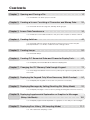
Contents
Chapter 1 Opening and Closing a File - - - - - - - - - - - - - - - - - - - - - - - - - - 1-1
You will start ZM-71SE and open/close a file.
Chapter 2 Creating a Screen Consisting of Characters and Bitmap Data - - - 2-1
You will create a new file using text, bitmap, and logotype.
Chapter 3 Screen Data Transference - - - - - - - - - - - - - - - - - - - - - - - - - - - 3-1
You will transfer screen data created on the personal computer to ZM-80 or ZM-70.
Chapter 4 Creating Switches - - - - - - - - - - - - - - - - - - - - - - - - - - - - - - - - - 4-1
You will create switches which set/reset bits in the PLC memory when they are
pressed/released. You will also create a screen change switch.
Chapter 5 Creating Lamps - - - - - - - - - - - - - - - - - - - - - - - - - - - - - - - - - - 5-1
You will create lamps.
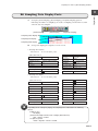
Chapter 6 Creating PLC Numerical Data and Character Display Parts - - - - - 6-1
You will display numerical data and character display parts.
Chapter 7 Changing the PLC Memory Data through Keypad - - - - - - - - - - - 7-1
You will change the data in the PLC memory directly through the keypad placed on
the screen.
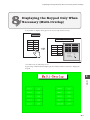
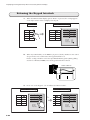
Chapter 8 Displaying the Keypad Only When Necessary (Multi-Overlap) - - - 8-1
You will display the keypad on the screen only when it is necessary.
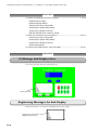
Chapter 9 Displaying Messages by Setting/Resetting Bits (Relay Mode) - - - - 9-1
You will display messages on the screen by setting/resetting bits in the PLC memory.
Chapter10 Displaying Supplemental Explanation or Graphics to Messages
(Relay-Sub Mode) - - - - - - - - - - - - - - - - - - - - - - - - - - - - - - - 10-1
You will display supplemental explanation or graphics to the relay-mode messages.
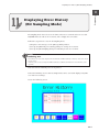
Chapter11 Displaying Error History (Bit Sampling Mode) - - - - - - - - - - - - - 11-1
You will create a bit sampling screen.
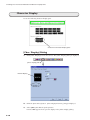
Chapter12 Expressing Time-Varying Data in a Line Graph
(Trend Sampling Mode)
- - - - - - - - - - - - - - - - - - - - - - - - - - 12-1
You will create a trend sampling screen.
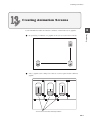
Chapter13 Creating Animation Screens
- - - - - - - - - - - - - - - - - - - - - - - 13-1
You will create the screens which graphics and figures are moved on.
Chapter14 Calendar Display
- - - - - - - - - - - - - - - - - - - - - - - - - - - - - - 14-1
• You will create a screen to adjust the calendar.
• You will modify calendar parts.
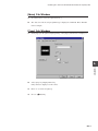
Option
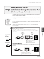
Using Memory Cards as External Storage Media for a PLC
(The Memory Manager Function)
- - - - - - - - - - - - - - - - Option-1
Opening and Closing a File
1
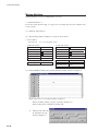
Starting
1
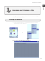
Opening and Closing a File
This chapter describes how to open and close a file on ZM-71SE (screen editing
software for Windows 95/98/NT4.0).
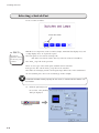
Starting the Software
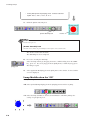
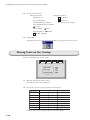
1.
Double-click the program icon. Or, click [Start] of Windows 95, and click
[Programs], [Zm-71s] then [ZM-71S].
or
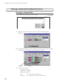
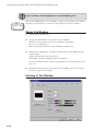
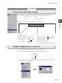
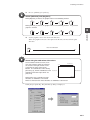
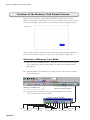
2.
The following ZM-71SE initial screen is displayed.
1-1
Opening and Closing a File
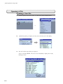
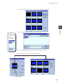
Opening a File
Opening a New File
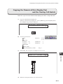
1.
Click the [New] icon in the tool bar, or select [New] from the [File] menu.
or
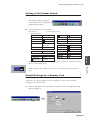
2.
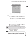
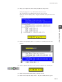
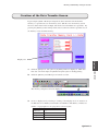
[Edit Model] dialog is displayed. Select the model name, then click [OK].
3.
The [Select PLC Type] dialog is displayed.
Select as default (SHARP : JW series), then click [OK] to display [Screen [0]
Editing] window.
1-2
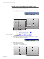
Opening and Closing a File
1
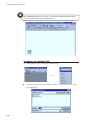
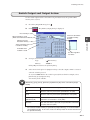
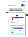
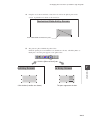
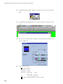
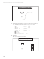
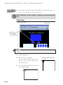
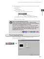
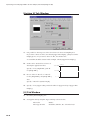
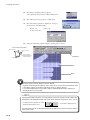
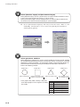
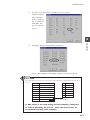
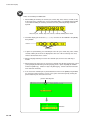
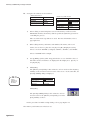
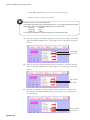
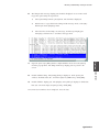
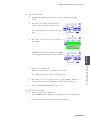
4.
Starting
When the type of the PLC was changed, [Communication Parameter] dialog is
displayed first, then [Screen [0] Editing] window is displayed.
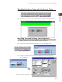
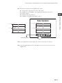
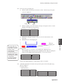
The window can be adjusted to the desired size when necessary.
(Red frame size represents the size of the display of 800 x 600 dots.Red dotted line
represents the size of the editing model.)
1-3
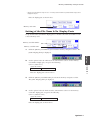
Opening and Closing a File
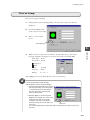
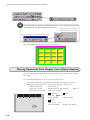
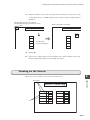
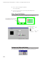
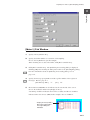
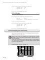
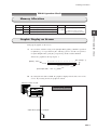
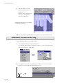
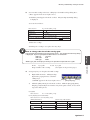
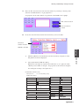
When [Editing Model: ZM-41 (320*240)] is selected, the following window will appear.
Screens should be editted within the dotted lines.
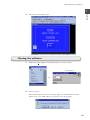
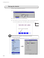
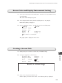
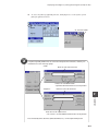
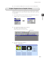
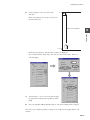
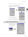
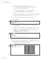
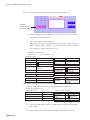
Opening an existing file
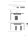
1.
Click [Open] icon for [Open(O)] in [File(F)] menu.
Or...
2.
1-4
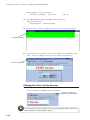
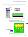
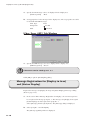
A dialog to select the file will be displayed. Select a screen data file to be editted
then click [Open].
Opening and Closing a File
1
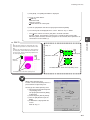
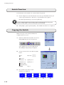
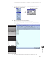
Selected screen data file is open.
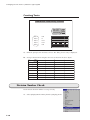
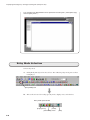
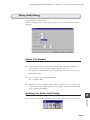
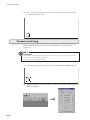
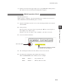
Ending
3.
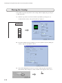
Closing the software
1.
Click either [(Quit Application)] in [File(F)] menu or [Close] button.
Close button
Or...
2.
Screen is closed.
If the modified data is not saved, the dialog appears to confirm whether the data
will be saved or not. Click either [Yes] or [No] to close the program.
1-5
Creating a Screen Consisting of Characters and Bitmap Data
2
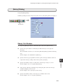
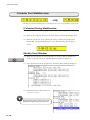
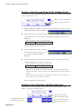
Procedure
2
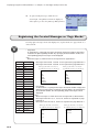
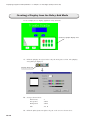
Creating a Screen Consisting of
Characters and Bitmap Data
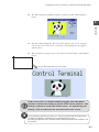
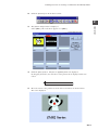
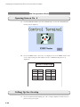
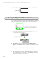
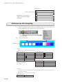
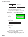
You will create the following screen.
This is the initial screen to be displayed at start-up.
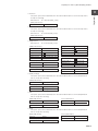
Procedure
1) Opening a new file • • • • • • • • • • • • • • • • • • • • • • • • • • • • • • • • • • • • • P2-2
Set up [Edit Model] and [Select PLC Type].
2) Creating a screen title (screen editing) • • • • • • • • • • • • • • • • • • • • • • • P2-3
The [Text] icon in the draw tool bar is used.
3) Importing bit map data (screen editing) • • • • • • • • • • • • • • • • • • • • • • • P2-6
[Paste bitmap] in the [Tool] menu is used.
4) Creating logotype (pattern editing and screen editing) • • • • • • • • • • • • • P2-8
The [Text] icon in the draw tool bar is used for pattern editing.
The logotype is imported to the screen editing window using the draw tool
bar.
2-1
Creating a Screen Consisting of Characters and Bitmap Data
Operation
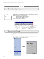
Before Creating a Screen
After starting ZM-71SE, follow the procedure below:
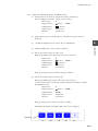
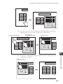
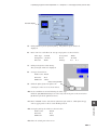
1.
For
Open a new file.
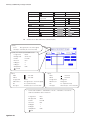
Click the [New] icon. The [Edit Model] dialog and [Select PLC Type] dialog are
displayed in sequence. Set up as shown below:
ZM-70
Select
"ZM-70 (640*480) (16Color)" from "Edit Model".
Edit Model: ZM-82 (640*480 10.4 inches)
Select PLC Type: SHARP: JW series
`
[Screen [0] Edit] window is displayed.
2.
The draw tool bar is mainly used in this chapter. Check the meaning of each icon.
Line
Pattern
Box
Text
Circle
Paint
Dot
Bar graph scale
Graphic Call
Screen Library
Multi Text
Trend graph scale
Pie graph scale
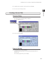
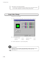
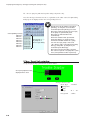
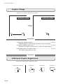
Screen Color Change
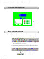
At start-up, the screen color is black. The color can be changed with the following
steps:
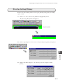
1.
Click [Edit] menu. The following pull-down menu is displayed.Click [Screen
Setting]. The [Screen Setting] dialog is displayed.
2-2
Creating a Screen Consisting of Characters and Bitmap Data
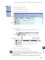
2.
In [Back Color], check blue for [F (foreground) ]. Click [OK].
3.
The screen color is changed to blue.
2
Operation
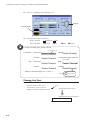
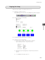
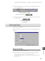
Creating a Screen Title
Character Entry
1.
Click [Text] icon in the draw tool bar.
The following [Screen Drawing] dialog is displayed.
The cursor blinks in the box.
2.
Key in "Control Terminal".
Property Setting
1.
Set up properties for "Control Terminal".
In the [Screen Drawing] dialog, check red for [Foreground] and yellow for
[Background].
The text image appears in the preview display.
2-3
Creating a Screen Consisting of Characters and Bitmap Data
2.
Enter "3" for [Enlarge X] and [Enlarge Y].
Enlarge
Preview display
3.
Set up the other options as follows:
Rotate: Normal
Transparent
Normal
Direction: RGT
Italic
1/4
Bold
Shadow
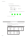
A variety of character types can be selected.
Background color
Transparent
unchecked:
Normal:
Control Terminal
Control Terminal
checked:
1/4(Invalid for 2-byte characters):
Control Terminal
Italic
unchecked:
Bold:
Control Terminal
checked:
Control Terminal
Control Terminal
Control Terminal
Shadow:
Control Terminal
Foreground Color
* "Bold" is valid when Enlarge is X : 1 and Y : 1.
(Enlarged)
C
Background Color
Placing the Text
1.
Place the text on the screen.
Drag the mouse on the screen.
A dotted box of the text size is
displayed and moved with the mouse.
Drag
Drag the mouse on the screen.
A dotted box of the text size appears.
2-4
Creating a Screen Consisting of Characters and Bitmap Data
2.
Upon releasing the mouse button, the text appears on the screen.
2
Control Terminal
3.
Operation
Release the mouse button.
The text is displayed.
To adjust the text position, click the [Select] icon. The mouse cursor changes
from a cross to an arrow.
Click the text. Handles are shown
around the text.
Control Terminal
Click the text.
Control Terminal
[Select] icon
Eight handles are shown around the text.
4.
Drag the text to the upper center of the screen.
Control Terminal
To modify text properties (color or character type), click the [Detail/Prop. Change]
icon in step 3 (while handles are shown around the text) , or double-click the text.
2-5
Creating a Screen Consisting of Characters and Bitmap Data
Bitmap File Import
With ZM-71SE, it is possible to import a bitmap file (extension: [.bmp]) to the screen
easily. Using this function, company logotype or graphics can be imported with ease.
Import the following bitmap data.
When ZM-71SE is installed, the bitmap data is also automatically installed into the
[\Zm-71s\Parts] folder under the file name of "panda.bmp".
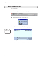
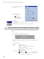
1.
When the [Screen [0] Edit] window is displayed, select [Paste Bitmap] from the
[Tool] menu.
The [Open a bitmap file] dialog is displayed.
2.
2-6
Select [panda.bmp] from the "Parts" folder and click [Open].
Creating a Screen Consisting of Characters and Bitmap Data
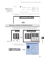
3.
The dialog showing the bitmap is displayed. When it is O.K., click the [Place]
button.
2
Operation
4.
The above dialog disappears. The cross cursor appears on the screen. Drag the
cursor to the center of the screen. A dotted box of the bitmap size also appears
with the cursor.
5.
When the mouse is dragged to the center, release the mouse button. The bitmap is
placed.
Drag the bitmap and release the mouse button.
The bitmap is placed in the position.
If the cross cursor is clicked without dragging after the [Place]
button is clicked, the bitmap is placed in the cursor position. The
bitmap is placed on each click of the cursor. To quit placing the
bitmap, click the [Select] icon and cancel the cross cursor.
Once a bitmap is placed on the screen, it is saved in the pattern edit file automatically.
Therefore, the bitmap is retained even if it is deleted from the screen.
By clicking the [Pattern] icon in the draw tool bar, bitmap data registered as patterns can
be checked.
2-7
Creating a Screen Consisting of Characters and Bitmap Data
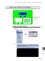
Creating Logotype
Characters in the desired font and size can be created and imported to the screen easily.
Such characters are created in the units of dots and saved in pattern edit file.
Create the logotype as shown below.
Create this logotype.
Entering the Dot Editing Area
2-8
1.
Click the [Item] menu. The following pull-down menu appears. Click [Pattern].
2.
The [Pattern] dialog for entering a pattern No. is displayed. Check that "0" is
entered and click [OK].
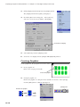
Creating a Screen Consisting of Characters and Bitmap Data
3.
The [Pattern [0] edit] window is opened.
Check that the bitmap previously imported using [Paste bitmap] is registered as
pattern No. 0.
Panda's ear
2
Operation
To delete the stored pattern (bitmap), open the window of the pattern number and select
[All delete] from the [Edit] menu.
Only the pattern in the opened window is cleared.
4.
Store the logotype in pattern No. 1. Click the [Next] icon in the tool bar to open
the [Pattern [1] Edit] window.
Click this icon.
Modifying the Dot Editing and Display Size
1.
Adjust the editing area size to the text.
Select [Change Size] from the [Transform] menu.
2-9
Creating a Screen Consisting of Characters and Bitmap Data
2.
The following message appears. Click [Yes].
3.
The [Size Change] dialog is displayed. Enter the desired values in dots as shown
below. Click [OK].
X Size: 300
Y Size: 35
4.
Color: 128-color
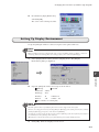
Decrease the [Zoom] value for convenient editing.
Select [Display Environment] from the [Display] menu.
The [Display Environment] dialog is displayed. Select [200 %] and click [OK].
The window is decreased.
35dots
300 dots
2-10
Creating a Screen Consisting of Characters and Bitmap Data
Matching the Area Color with the Screen Color
1.
Click the [Paint] icon in the draw tool bar for pattern edit.
2
Because the screen color is blue, check blue for [Foreground] and click anywhere
on the dot editing area. The area color is changed to blue.
Entering Text and Setting Text Properties
1.
Click the [Text] icon. The [Pattern Drawing] dialog is displayed.
2.
As done is the [Screen Drawing] dialog (Page 2-3), key in "ZM82 Series".
3.
Set up text properties,such as font and size.Click [Font]. The following [font]
dialog is displayed.
Specified font image is displayed.
2-11
Operation
2.
Creating a Screen Consisting of Characters and Bitmap Data
In this example, set up as shown below:
Font:Times New Roman
Style: Bold
4.
Size: 20
By clicking [OK], the [Pattern [1] Edit] window is displayed.
Select the desired colors.
Foreground: Red
Background: Blue
5.
Drag the mouse over the dot editing area. The box of the text size is displayed.
Drag in this position.
6.
Locate the mouse cursor in the center of the dot editing area, and click the mouse
button. The text is displayed. Now the text is registered as pattern No. 1.
Click in this position.
Placing the Text on the Screen.
1.
Click the "x" (close) button in the [Pattern [1] Edit] window. The window is
closed and the [Screen [0] Edit] window is displayed.
Click here to close the
[Pattern [1] Edit] window.
By selecting [Screen] from the [Item] menu, the [Screen [0] Edit] window is displayed
While the [Pattern [1] Edit] window is opened.
2-12
Creating a Screen Consisting of Characters and Bitmap Data
2.
Click the [Pattern] icon in the draw tool bar.
2
Operation
3.
The [Pattern List] window is displayed.
Select [0001]. The read cursor appears over [0001].
Cursor appears here.
4.
Click the [Place] button. The [Screen [0] Edit] window is displayed.
By dragging the mouse, the dotted box of the pattern size is displayed with cross
cursor.
5.
Move the cursor to the position as shown below and release the mouse button.
The text is displayed.
2-13
Creating a Screen Consisting of Characters and Bitmap Data
Saving the screen data
Save the created file.
1.
Click the [Save] icon in the tool bar, or select [Save] from the [File] menu.
2.
The following inquiry dialog appears. Click [Yes].
3.
The [Select a screen data to save] dialog is displayed.
Enter "Example1" in the text field and click the [Save] button.
For
ZM-70
Extension is [.Z71]
when a screen
data is saved.
Key in "Example1".
Now this screen file is saved under the file name of "Example1.Z71".
2-14
Screen Data Transference
3
Screen Data Transference
3
We will transfer the screen data (file name: "Example1.Z71") created in Chapter 2 to
Procedure
1) ZM-70 setup • • • • • • • • • • • • • • • • • • • • • • • • • • • • • • • • • • • • • • • • • P3-1
Turn on ZM-70 and connect it with a PC.
2) Connecting a PLC to ZM-70 • • • • • • • • • • • • • • • • • • • • • • • • • • • • • • P3-2
Connect a PLC to ZM-70
3) Transferring the screen dat to ZM-70 • • • • • • • • • • • • • • • • • • • • • • • • P3-3
Transfer the screen dat from the PC to ZM-70
4) Communication start between ZM-70 and PLC. • • • • • • • • • • • • • • • • • P3-5
Press the [SYSTEM] key and [F 1] key of ZM-70 so that it start to run.
Operation
Before Data Transference
Start up ZM-70.
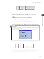
1.
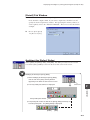
When the ZM-70 is turned on first (after being unpacked), the following screen is
displayed.
* The following screen is not displayed if screen data has already been
transferred to ZM-70.
3-1
ZM-70 Procedure
ZM-70.
The process is different between ZM-70 and ZM-80. See P3-8 for the details.
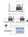
Screen Data Transference
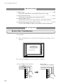
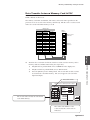
2.
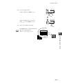
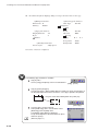
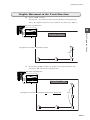
Connect ZM-70 to the computer with a data transfer cable "ZM-82C". Screen data
transfer port on the ZM-80 side is "MJ1".
Personal Computer
ZM Series
ZM-82C
MJ1
Modular
8pin
D-sub 9pin
Adaptors are included in V6-CP set.
These adaptors are not necessary when DOS/V computer is used.
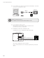
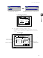
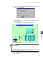
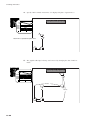
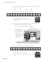
3.
Connect ZM-70 and a PLC in advance.
Match parameters such as baudrate or parity on the PLC side with
[Communication Parameter] on ZM-70 side.
4.
Link ZM-70 to the PLC with a communication cable.
Communication connector on ZM-70 side is CN1 (D-sub 25 pin).
Rear side of ZM-70
TB1
PLC
(+)
DC 24V
(−)
MJ2
MJ1
Cable
(Have a cable depending on PLC)
CN1
CN2
Connect the CN1 (D-sub 25 pin) of ZM-70
with PLC using a communication cable.
Have a proper communication cable for your PLC.
For the connecting instruction, refer to "Hardware Specifications" provided with
ZM-80.
3-2
Screen Data Transference
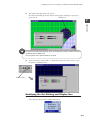
Transferring the Screen Data
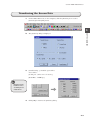
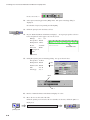
1.
On the ZM-71SE screen (on the computer), click the [Transfer] icon or select
[Transfer] from the [File] menu.
3
The [Transfer] dialog is displayed.
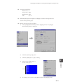
3.
[Detail Setting ...] should be opened first.
ZM-70 Operation
2.
Set as below :
[Serial port : (Select one to be used.) ]
[Baud Rate : 57600 bps]
Maximum of the
baudrate varies
according to the
model of PC.
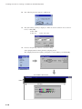
4.
Click [OK] to return to the [Transfer] dialog.
3-3
Screen Data Transference
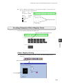
5.
Set up as shown below:
Transfer device
Transfer Data
Use Simulator
: ZM-70
: Screen Data
Read comments in data transfer
6.
Click [PC->]. The [Transferring] dialog is displayed on the computer.
After the I/F driver data is transferred, the screen data is transferred.
The [Transferring] dialog on the computer.
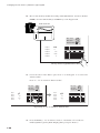
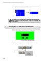
7.
After the I/F drive data is transferred, the screen data is transferred.
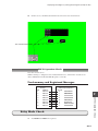
"Main Menu" screen appears upon the completion of the data transfer.
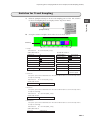
ZM-72T
Main Menu
System Information
SYSTEM PROG. VER.1.000
Screen Data
Information
容量 : 786432
FONT
VER.1.000/1.000/1.000
ENGLISH
PLC Type:SHARP JW Series
Comment:
1998- 9- 1 07:23:30
I/F DRV VER. 1.000
MELSEC JW
Error:Stop
Time-Out:0.50 sec
Retry:3
Connection:1:1 Baud Rate:19200
Signal Level:RS232C Data Length:7
PLC Stat.No:0 Stop Bit:1
Parity:Even
Send Delay:0msec
Editor : MJ1
Memory-Card
I/O Test I/F driver
This is a protocol file necessary for communication between ZM-70 and PLC or ZM-70 and a general-purpose
computer. If the I/F driver does not conform to PLC connected to ZM-70, communication will not be executed
correctly.
3-4
Screen Data Transference
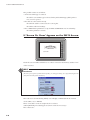
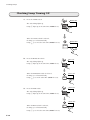
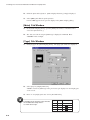
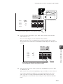
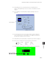
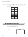
ZM-80 Operation Check
1.
Make sure whether ZM-70 is connected to the PLC. Press [SYSTEM] key.
The screen created on the PC appears.
Pi!
S
Y
S
T
E
M
M
O
D
E
M
O
D
E
3
ZM-70 Operation Check
S
Y
S
T
E
M
The screen created on the computer is displayed.
PLC
If Communication between ZM-70 & PLC Is Not Successful:
If "Communication Error" Appears on the ZM-70 :
Communication Error
Time-Out
Screen No.:
Received Code No.:
RETRY
3-5
Screen Data Transference
The possible causes are as follows:
• An incorrect PLC type is selected.
Check if a correct PLC type is selected in the [Select PLC Type] dialog when a
new screen is opened.
• The cable is connected incorrectly.
Check if the cable is connected to the correct pins.
Check the cable for breakage.
• The communication parameters set up for PLC and ZM-80 are not in conformity.
Check the parameter contents.
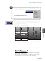
If "Screen No. Error" Appears on the ZM-70 Screen:
Check
Screen No. Error
Check if a screen number which does not exist is entered for the memory address "n+2"
of the read area.
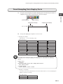
Read area
[Read Area] is set up in the [Comm. Parameter] dialog. To bring up the dialog, select [System Setting] from the
[Item] menu and click [Comm. Parameter].
The read area is for transferring mainly screen display commands from an external
device (PLC, etc.) to ZM-70.
Three consecutive words are assigned to the read area.
(When [Buffering Area Setting] is used, more words are necessary.)
The contents are:
3-6
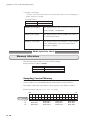
Screen Data Transference
Address
n
Name
Contents
RCVDAT
Sub command
n+1
SCRN_COM
Screen status command
n+2
SCRN_No
External screen number command
When communication starts between PLC and ZM-70, the screen of the number stored
in the read area "n+2" is opened first.
If the screen number does not exist, the "Screen No. Error" message is given.
3
Therefore:
D00002 = 0
ZM-70 Operation Check
<Ex.>
D00000 is entered for [Read Area] for the file "Example1.Z71".
Screen No. 0 is indicated.
D00002 = 10
"Screen No. Error" is given.
(Because screen No. 10 is not included in the "Example1.Z71" file.)
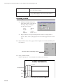
The screen number displayed on the ZM-70 screen is written to the Write Area "n+2".
Write Area
[Write Area] is set up in the [Comm. Parameter] dialog. To bring up the dialog, select [System Setting] from the
[Item] menu and click [Comm. Parameter].
The write area is for writing mainly screen status data from ZM-80 to an external device (PLC, etc.).
Similar to the Read Area, three consecutive words are assigned to the Write Area.
The contents are:
Address
n
Name
Contents
CFMDAT
Same as those in the read area "n"
n+1
SCRN_COM
Screen status
n+2
SCRN_No
Display screen number
The contents of the three words and those of the write area are mostly in pairs.
The screen number to be displayed is commanded from the "n+2" Read Area to ZM-70,
and the screen number displayed on ZM-70 is written to the "n+2" Write Area.
3-7
Screen Data Transference
ZM-70 Procedure
1) ZM-70 setup • • • • • • • • • • • • • • • • • • • • • • • • • • • • • • • • • • • • • • • • • P3-8
Bring up the "Main Menu" screen on ZM-70 and set in a stop.
2) Screen data transference • • • • • • • • • • • • • • • • • • • • • • • • • • • • • • • P3-10
Transfer the screen data from the computer to ZM-70.
3) Connecting ZM-70 to PLC • • • • • • • • • • • • • • • • • • • • • • • • • • • • • • • P3-12
Connect ZM-70 to PLC after transferring the screen data to ZM-70.
4) Communication start between ZM-70 and PLC. • • • • • • • • • • • • • • • • P3-12
Press the [SYSTEM] key and [F 1] key of ZM-70 so that it start to run.
ZM-70 Operation
Before Data Transference
Start up ZM-70
1.
When the ZM-70 is turned on first (after being unpacked), the following screen is
displayed.
SYSTEM
F 1
Check
F 2
F 3
F 4
PLC I/F Driver not setting
F 5
F 6
F 7
POWER
2.
RUN
Press the [SYSTEM] key and then the [F1] key on ZM-70.
Press the SYSTEM key to call up the menu.
Press the F1 key
while the "Mode" menu is displayed.
Pi !
S
Y
S
T
E
M
M
O
D
E
3-8
SYSTEM
F 1
S
Y
S
T
E
M
M
O
D
E
SYSTEM
F 1
F 2
F 2
F 3
F 3
Screen Data Transference
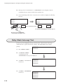
3.
The "Main Menu" screen is displayed on ZM-70.
The following message appears in the left corner of the screen.
The message may be ignored because it means that ZM-70 is new and stores no
screen data yet.
ZM-70 Type
ZM-70 ROM Version
Main Menu
Ver1.25 1M
FP-ROM Capacity
("1M" appears for 1M byte.
Nothing appears for 512K bytes.)
PLC I/F DRV.
Name:
ZM-70T
Ver.
3
SYSTEM
1997- 4- 1 10:10:00
F 1
Signal Level: RS422
Connection: Multi-Link
PLC Stat.No.: 31
Baud Rate: 38400
Data Length: 8
Stop Bit: 2
Parity: Even
ZM-70 Procedure
Error: Retry
Time-Out: 42.94 sec
Retry: 255
Code: BCD
Character: MSB -> LSB
PLC Type:
Comment:
F 2
F 3
Multi-Link Network
Own Stat.No.:
ZM70 Total:
Send Delay:
Retry:
F 4
msec
F 5
F 6
PLC I/F Driver not setting
POWER
I/O Test
Memory-Card
F 7
RUN
This message appears when a new ZM-70 is turned on first.
4.
Connect ZM-70 to the computer used for screen editing using the screen data
transfer cable. For a DOS/V computer, use our cable ZM-82CV.
*[ZM-82C]
DOS/V computer
ZM Series
ADP25-M
ZM-82C
SYSTEM
F 1
F 2
F 3
F 4
F 5
F 6
F 7
POWER
Modular
8pin
D-sub 9pin
RUN
D-sub 25pin
*[ZM-82CV]
DOS/V computer
ZM Series
ZM-82CV
SYSTEM
F 1
F 2
F 3
F 4
F 5
F 6
F 7
POWER
D-sub 9pin
RUN
D-sub 25pin
3-9
Screen Data Transference
Transferring the Screen Data
1.
On the ZM-71SE screen (on the computer), click the [Transfer] icon or select
[Transfer] from the [File] menu.
2.
The [Transfer] dialog is displayed.
Set up as shown below:
Transfer Device
Transfer Data
: ZM-70
: Screen Data
Use Simulator
Read comments in data transfer
Click [PC -> ].
When the screen data is transferred first, the I/F driver data is
also transferred automatically.
3.
The [Transferring] dialog is displayed on the computer. After the I/F driver data is
transferred, the screen data is transferred.
The ZM-70 screen also brings up the [Transferring] dialog.
3-10
Screen Data Transference
The [Transferring] dialog on the computer.
After the I/F drive data is transferred, the screen data is transferred.
3
This window appears during transference.
PLC I/F DRV.
Name:
ZM-70T
Ver.
ZM-70 Operation
Main Menu
Ver1.25 1M
SYSTEM
Receive 1997- 4- 1 10:10:00
Send
Error: Retry
Time-Out: 42.94 sec
Retry: 255
Code: BCD
Character: MSB -> LSB
PLC Type:
Comment:
Signal Level: RS422
Connection: Multi-Link
PLC Stat.No.: 31
Baud Rate: 38400
Data Length: 8
Stop Bit: 2
Parity: Even
F 1
F 2
F 3
Multi-Link Network
Own Stat.No.:
ZM70 Total:
Send Delay:
Retry:
msec
F 4
F 5
F 6
PLC I/F Driver not setting
POWER
4.
I/O Test
Memory-Card
F 7
RUN
Upon completion of transference, the dialogs disappear.
On the ZM-70 screen, the PLC type selected when creating the screen on the
computer is displayed. This means that the I/F driver data has been transferred
normally.
PLC I/F Driver Version
Main Menu
Ver1.25 1M
PLC Type: SHARP JW series
Comment:
PLC Type and Comment
included in the screen data
Signal Level: RS232C
Connection: 1:1
PLC Stat.No.: 0
Baud Rate: 19200
Data Length: 7
Stop Bit: 1
Parity: Even
Communication Parameters
ZM-70T
PLC I/F DRV.
Ver 1.45
Name: MELSEC JW
SYSTEM
1997- 4- 1 10:10:00
Error: Stop
Time-Out: 0.50 sec
Retry: 3
Code: DEC
Character: LSB -> MSB
PLC I/F Driver Type
F 1
F 2
F 3
Multi-Link Network
Own Stat.No.:
ZM70 Total:
Send Delay:
Retry:
msec
F 4
Multi-Link Setting
F 5
* Displayed only for the
multi-link connection type.
F 6
I/O Test
POWER
Memory-Card
F 7
RUN
3-11
Screen Data Transference
ZM-70 Operation Check
Connection and Communication with PLC
1.
Set up the same communication parameters such as baud rate and parity for ZM70 and PLC.
For ZM-70, check the "Main Menu" screen data.
For PLC, set up the data while referring to the PLC manual.
Communication Parameters
Main Menu
Ver1.25 1M
ZM-70T
PLC I/F DRV.
Ver 1.45
Name: MELSEC JW
PLC Type: SHARP JW series
Comment:
Signal Level: RS232C
Connection: 1:1
PLC Stat.No.: 0
Baud Rate: 19200
Data Length: 7
Stop Bit: 1
Parity: Even
SYSTEM
1997- 4- 1 10:10:00
Error: Stop
Time-Out: 0.50 sec
Retry: 3
Code: DEC
Character: LSB -> MSB
F 1
F 2
F 3
Multi-Link Network
Own Stat.No.:
ZM70 Total:
Send Delay:
Retry:
msec
F 4
F 5
F 6
I/O Test
POWER
2.
Memory-Card
F 7
RUN
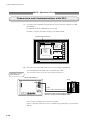
Disconnect the cable (ZM-82CV) between the computer and ZM-70.
Connect ZM-70 and the PLC with a communication cable.
(Use the CN1 connector used for screen data transference.)
For ZM-41, use the
CN2 connector.
Rear side of ZM-70
CN1
TB1
PLC
TB2
CN1
S1
CN6
CN2
CN5
CN7
CN4
Cable
(Have a cable depending on PLC.)
CN3
Connect the CN1 (D-sub 25 pin) of ZM-70
with PLC using a communication cable.
Have a proper communication cable for your PLC.
For the connecting instructions, refer to "Hardware Specifications" provided with
ZM-70.
3-12
Screen Data Transference
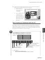
3.
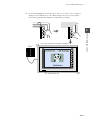
Press the [SYSTEM] key and the [F 1] key. The screen created on the computer is
displayed on the ZM-70 screen. The "RUN" lamp in the lower left corner lights
up, indicating that ZM-70 and PLC are communicating normally.
Pi !!
S
Y
S
T
E
M
M
O
D
E
S
Y
S
T
E
M
SYSTEM
M
O
D
E
F 1
SYSTEM
3
F 1
F 2
F 3
F 3
ZM-70 Operation Check
F 2
The screen created on the computer is displayed.
PLC
SYSTEM
F 1
F 2
F 3
F 4
F 5
F 6
F 7
POWER
RUN
RUN lamp lights up.
3-13
Creating Switches
4
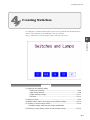
Creating Switches
You will place a standard switch which sets/resets the specified bit in the PLC memory
when it is pressed/released, and will place four copy switches.
Also, you will create a screen change switch on the previous screen.
4
Procedure
Operation
Procedure
1) Setting up the [Switch] dialog
• Switch part selection • • • • • • • • • • • • • • • • • • • • • • • • • • • • • • • • • P4-4
• Color and characters • • • • • • • • • • • • • • • • • • • • • • • • • • • • • • • • • P4-8
• Output memory setting • • • • • • • • • • • • • • • • • • • • • • • • • • • • • • • P4-11
• Function • • • • • • • • • • • • • • • • • • • • • • • • • • • • • • • • • • • • • • • • • P4-12
2) Placing a switch • • • • • • • • • • • • • • • • • • • • • • • • • • • • • • • • • • • • • • • P4-6
3) Making switch copies and setting up the [Switch] dialog • • • • • • • • • • • P4-12
4) Creating a screen change switch • • • • • • • • • • • • • • • • • • • • • • • • • • P4-14
Function setting, color and part shape modification
5) Placing a screen change switch on the previous screen • • • • • • • • • • • P4-15
4-1
Creating Switches
Operation
Creating a New Screen
Click the [Next] icon to open a new screen.
[Screen Skip] icon
[Next] icon
When the [Screen Skip] icon is selected, a new screen cannot be opened by clicking the
[Next] icon.
Screen Color
Select the desired screen color.
1.
Select [Screen Setting] from the [Edit] menu. The [Screen Setting] dialog is
displayed.
2.
Check white for [F (foreground)].
3.
Click the [OK] button to quit the [Screen Setting] dialog.
Now the screen color is changed to white.
When a new screen is opened, it has the data of [Screen Setting] (except [Item Select
Memory]) set up for the previous screen.
4-2
Creating Switches
Creating a Screen Title
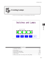
Create the screen title "Switches and Lamps".
1.
Click the [Text] icon in the draw tool bar. The [Screen Drawing] dialog is
displayed.
2.
Key in "Switches and Lamps". Set up text properties and place the title in the
upper center of the screen.
Foreground : Black
Enlarge X
Rotate
:3
: Normal
Background
: Purple
Enlarge Y
Direction
:3
: RGT
Shadow
4
[Select] icon
Operation
3.
Click the [Select] icon to close the [Screen Drawing] dialog.
To place the title in the center:
1) Select [Align] from the [Edit] menu and
click [Align Setting]. The [Align Setting]
dialog is displayed.
2) Check that [ Equal] is chosen for [Pitch].
Check the [Selected Area] box( ) and
click the [OK] button.
3) Enclose the title using the mouse. The coordinates are as shown below. A dotted
box appears.
(Coordinates 0 : 0)
Switches and Lamps
(Coordinates 639:79)
Dotted Box
4) Select [Align] from the [Edit] menu and click [Vertical Align] or [Horizontal Align].
5) The title is placed in the center of the dotted box.
6) To prevent the box from appearing again in the next operation, uncheck the
[ Selected Area] box in the [Align Setting] dialog and click the [OK] button.
4-3
Creating Switches
Selecting a Switch Part
Create a switch as follows.
Create this switch.
For
ZM-70
Basic parts are
registered in "Std.zmp".
Also our "Parts_e.z7p"
is provided.
ZM-70 screen components, such as switches, lamps, numerical data display areas, and
overlap display areas, are registered as parts.
The basic parts are stored in the "Std.z7p" file.
(The file is stored in the "Parts" directory when the software is installed.)
The "Parts_e.z7p" file is also provided.
There are two types of the switch parts: standard and non-standard.
Part types No. 0 to 3 in the "Parts_e.z7p" file are the standard.
The methods of changing switch color and part shape differ between the standard and
the non-standard parts. Choose the standard type in this example.
Under total available memory capacity for one screen, a maximum of 500 switches can
be created.
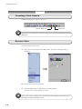
1.
Click the [Switch] icon in
the tool bar. The [Switch]
dialog is displayed.
[Switch] icon
4-4
Creating Switches
2.
Click the [Parts Select] button. [Switch List (Std.z7p) ] is displayed.
4
ZM-70
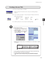
3.
Click [Parts File] and open the "Parts_e.z7p" file.
4.
Select [0002] from [Switch List], and click the [Select] button.
5.
The selected part appears in the preview display.
Operation
For
Change [Files of type]
to [*.z7p] to select ZM70 parts file.
Select "Parts_e.z7p",
then click [Open].
Switch part No. 0002 appears.
Preview display
4-5
Creating Switches
Placing the Switch
Place the selected switch part on the screen.
1.
Check that "0" is entered for [Division No.].
2.
Click the [Place] button in the [Switch] dialog.
3.
The switch area as shown on the right appears. Move it to the lower left corner of
the screen and click the mouse. The switch is placed as shown below:
Place the switch in this position.
When the switch area is dragged, it is moved along the switch grids.
To bring up the switch grids:
1) Select [Display Environment] from the [Display] menu. The [Display Environment]
dialog is displayed.
4-6
Creating Switches
2) Click [Grid]. The [Grid] tab window is displayed.
3) Set up as shown below:
Grid Dsp.
Grid Color: Red
Grid Type: Switch
* Place switches on switch grids.
4) Click the [OK] button and close the [Display Environment] dialog.
5) The switch grids are displayed on the screen. Refer to <Fig. 1> below.
* The [ Place switches on switch grid.] box is checked as default.
Placing, moving, and enlarging a switch area is carried out along switch grids.
When the [Place switches on switch grid.] box is not checked, these operations are
carried out in the unit of dots.(1)
ZM-70
(1)
When the [Place switches on switch grids.] box is not
checked, these operations are carried out in the unit of
dots.
However, the switch operating area is always based on
the switch grids, and the switch becomes invalid in the
non-active area. Refer to the following explanation for
the switch operating area.
Operation
For
4
<Fig. 1>
Switch grids
Minimum switch size
Minimum
Switch grids
switch size
The dotted boxes show switch operating areas.
The dotted boxes show switch operating areas.
About switch operating area
A switch can be activated only when it is
pressed within the operating area.
To bring up the switch operating area:
1) Select [Display Environment] from
the [Display] menu.
The [Display Environment] dialog
is displayed.
2) Check the [Area] box for [Detail].
3) Click the [OK] button to quit the
dialog.
4) A dotted box is displayed on the
screen.
Refer to <Fig. 1>.
4-7
Creating Switches
Enlarging and Reducing the Switch
Enlarge the switch by one size along the grids in the X- and Y-axis directions.
(1)
(2)
1
1
1
1
or
To enlarge the switch, drag a handle using the mouse as above (1) or (2).
Text in Switch
Enter text to be placed in the switch.
Place "AUTO".
1.
Double-clicking the switch or selecting the switch (handles are shown) and
clicking the [Detail/Prop. Change] icon brings up the [Switch] dialog.
2.
Click [Character]. The [Character] tab window is displayed.
Cursor
[Detail/Prop. Change] icon
4-8
Creating Switches
3.
While the cursor is placed in text field No. 0, click [Char. Prop.].
The [Char. Prop. [No. 0]] dialog is
displayed. Set up as shown below:
Char. Type : Normal
Foreground : White
Transparent
Italic
Rotate
Direction
: Normal
: RGT
Enlarge
X:2
Y:2
The [Char. Prop.] dialog can be set up for text in each text field.
Key in "AUTO" in text field No. 0.
A maximum number of characters in a line depends on switch size and character size.
5.
Click the [OK] button. The text is displayed in the preview display in the [Switch]
dialog.
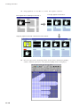
Checking the Switch Colors in the [Switch] Dialog
1.
Click [Main] in the [Switch] dialog. The [Main] tab window is displayed.
2.
By clicking the [ON] or [OFF] button, the switch ON color and OFF color can be
checked.
3.
Check that [XOR] is chosen for [Draw Mode].
4.
When the [ON] or [OFF] button is clicked, the switch colors are changed as
follows:
OFF color
OFF frame color
OFF character color
Blue
ON color
Red
White
White
ON frame color
ON character color
Green
Green
4-9
Operation
4.
4
Creating Switches
About XOR and REP
For a standard switch part
XOR: Switch frame and character colors are XORed with the selected colors.
For XOR, refer to "Chapter 17 Graphic Display: Graphic Colors" in the Reference
Manual.
REP: They are drawn in the selected colors.
Lamps in Switches (ON/OFF)
Choose whether the lamp of the switch lights up (in ON color)/goes off (in OFF color)
in internal process when it is pressed/released ([Lamp Memory] box unchecked) or the
lamp lights up/goes off with external commands from PLC ([Lamp Memory] box
checked).
AUTO
In this example uncheck the [Lamp Memory] box.
To turn on/off the lamp of the switch with external commands from PLC, check the [Lamp
Memory] box.
When the lamp memory bit in the PLC memory is set, the lamp lights up (in ON color).
When the bit is reset, the lamp goes off (in OFF color).
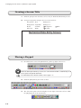
PLC Memory
.....
M 0∼15
M16∼31
The lamp is not turned on
even when the switch is pressed.
.....
STOP
STOP
PLC
The lamp is turned on when the lamp memory
bit in the PLC memory is set.
When the [Lamp Memory] box is checked and when 3-notch part is selected, it is
possible for one lamp to use three patterns of OFF, ON, and P3. The lamp memory
uses 2 bits in this case.
STOP
4-10
READY
RUN
Creating Switches
Switch Output and Output Action
Set the switch output action so that when it is pressed/released, the specified PLC
memory bit is set/reset.
1.
Check the [Output Memory] box ( ).
2.
Click
. The [Memory Input] dialog is displayed.
PLC memory is used.
Click here to indicate
available memory
devices.
ZM-70 memory is used.
(Refer to the Reference Manual.)
Value in memory card
is used for memory.
Available when
network is used.
Use this keypad to
set values.
3.
Set up as shown below:
Type
Memory
: PLC memory
: 09000-0
Click [OK] and return to the [Switch] dialog.
4.
4
Operation
Constant is used
instead of memory.
Select the desired option for [Output Action] so that the output to PLC is executed
when the switch is pressed.
To set/reset 09000-0 when the switch is pressed/released in this example, select
[Momentary] for [Output Action].
"R" memory is bit-writable.
[Momentary], [Set], [Reset], [Alternate] or [Momentary W] can be selected for [Output
Action].
Switch Action
Action output processing
Set
When the switch is pressed, the specified bit is set (ON).
Reset
When the switch is pressed, the specified bit is reset (OFF).
*Momentary
(Momentary W)
When the switch is held down, the specified bit is set (ON),
and when it is released, it is reset (OFF).
Alternate
Each time the switch is pressed, the specified bit is alternately
set (ON) and reset (OFF).
* If the non-bit-writable memory is specified for [Output Memory], it is recommended to
select [Momentary W]. In this case, results are directly written in the one-word area of
the specified memory.
4-11
Creating Switches
Switch Function
Set the function of the switch to be executed when it is pressed.
1.
In this example, the switch should just set/reset the specified PLC memory bit
when it is pressed/released. Therefore, no special function is required.
Check that [No Function] is selected for [Function].
To select a different option for [Function], click the [Change] button to bring up the
[Switch Function] dialog. Select the desired one from the dialog.
2.
Click [OK] to quit the [Switch] dialog. The AUTO switch has been completed.
Copying the Switch
Make four copies of the switch (AUTO) and
complete them one by one.
1.
Click the AUTO switch (handles are shown).
Click [Multi Copy] icon in the parts bar.
Select [Multi Copy] from the [Edit] menu.
The [Multiple Copy] dialog is displayed.
2.
Set up as shown below and click the [OK]
button.
Dot
Interval
X Distance: 19
Y Distance: 0
Memory INC
Direction:
①②③
④⑤⑥
Quantity X: 5
Quantity Y: 1
Switch Memory
09000-0
Step: 1
3.
Five switches (the master switch
inclusive) are displayed.
1st
4-12
2nd
3rd
4th
5th
Creating Switches
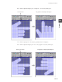
4.
Complete the MANUAL, RUN, and STOP switches.
(1) Double-click the 2nd switch. The [Switch] dialog is displayed.
Open the [Main] tab window. Set up as shown below:
Division No.
Output memory
:0
: checked
Lamp Memory
Output Action
: unchecked
: Momentary
Function
: No function
09000-1
(2) Click [Character] in the [Switch] dialog. The [Character] tab window is
displayed.
4
(3) "AUTO" is highlighted in the switch. Key in "MANUAL".
Operation
(4) Click the [OK] button. The switch is completed.
(5) For the 3rd switch, follow the same steps.
Bring up the [Main] tab window and set up as shown below:
Division No.
:0
checked
09000-2
unchecked
Output memory
Lamp Memory
:
:
Output Action
Function
: Momentary
: No function
Bring up the [Character] tab window and key in "RUN".
(6) For the 4th switch, follow the same steps.
Bring up the [Main] tab window and set up as shown below:
As this switch is turned on/off with external commands from PLC, check the
[Lamp Memory] box.
Division No.
:0
Output memory
Lamp Memory
: checked
: 09000-5
Output Action
Function
: Momentary
: No function
09000-3
Bring up [Character] tab window and key in "STOP".
The MANUAL, RUN, and STOP switches have been completed.
Completed
1st
2nd
3rd
4th
5th
4-13
Creating Switches
Creating a Screen Change Switch
and Modifying Color and Part
Create a screen change switch "NEXT".
1st
2nd
3rd
4th
5th
1.
Double-click the 5th switch. The [Switch] dialog is displayed.
2.
Set up the [Switch] dialog.
Division No.: 0
3.
Although the [Output Memory] box is checked and "09000-4" is entered, uncheck
it. Output is not made when the NEXT switch is pressed.
Output Memory: unchecked
4.
Lamp Memory: unchecked
5.
When the [Output Memory] box is not checked, [Output Action] is ignored.
6.
Click the [Change] button for [Function].
The [Switch Function] dialog is displayed.
Click [Screen]. Enter "2" for [Screen No.]. Click the [OK] button.
The [Main] tab window is displayed. [Screen: 2] is entered for [Function].
4-14
Creating Switches
7.
Change the switch color.
Click [Color] in the [Switch]
dialog. The [Color] tab window
is displayed.
8.
Set up as shown below:
Frame Color : Blue
ON Color : Yellow
OFF Color : White
9.
Choose the desired type from the following standard switch parts.
No Frame
Type 1
Type 2
Type3
4
Operation
Select [Type 3] for [Frame Type] in this example.
10. Change the switch text.
1) Click [Character] in the [Switch] dialog. The [Character] tab window is
2)
displayed.
To change character color, click [Char. Prop.] to display the [Char. Prop.]
3)
dialog.
Check blue for [Foreground], and set enlargement to X:1, Y:2, then click the
4)
[OK] button.
Key in "NEXT" in text field No.0.
11. Click the [OK] button.
12. For centering the characters on the switch,
select [NEXT] switch then select [Switch/
Lamp Centering] from [Edit] menu.
The NEXT switch has been completed.
4-15
Creating Switches
Placing the Screen Change Switch
on the Previous Screen
Place the screen change switch on screen No. 0.
Add this switch.
1.
Click the [Previous] icon to bring up the previous screen No. 0.
[Previous] icon
[Switch] icon
For
2.
Click the [Switch] icon in the tool bar. The [Switch] dialog is displayed.
3.
Bring up the [Main] tab window. Set up as shown below:
ZM-70
Select No.0002 from
"Parts_e.z7p"
4.
Parts Select
Division No.
: No. 0002 in [Switch List Parts_e.z7p]
:0
Output memory
Lamp Memory
:
:
Output Action
Function
: Momentary (to be ignored)
: Screen: 1
unchecked
unchecked
Bring up the [Character] tab window. Key in "NEXT".
Set up properties as shown below:
Char. Type : Normal
Foreground : White
Transparent: checked
5.
Rotate
Direction
: Normal
: RGT
Enlarge
X:1
Y:2
Bring up the [Color] tab window. Set up as shown below:
Frame Color : White
ON Color : Red
OFF Color : Blue
4-16
Italic : unchecked
Creating Switches
6.
Click the [Place] button in the [Switch] dialog.
This step completes the NEXT switch.
7.
Click the [Save] icon to save the created screen.
[Save] icon
Switch operation check is explained in Chapter 5.
4
Operation
4-17
Creating Lamps
5
Creating Lamps
On the screen created in Chapter 4, we will add lamps as shown below.
5
Procedure
Operation
Create these lamps.
Procedure
1) Choosing a lamp part • • • • • • • • • • • • • • • • • • • • • • • • • • • • • • • • • • • P5-2
2) Placing lamps • • • • • • • • • • • • • • • • • • • • • • • • • • • • • • • • • • • • • • • • P5-3
3) Lamp shape modification • • • • • • • • • • • • • • • • • • • • • • • • • • • • • • • • P5-4
4) Setting up the [Lamp] dialog • • • • • • • • • • • • • • • • • • • • • • • • • • • • • • P5-8
5) Color change • • • • • • • • • • • • • • • • • • • • • • • • • • • • • • • • • • • • • • • • P5-10
6) Making lamp copies and setting up the [Lamp] dialog • • • • • • • • • • • • P5-11
5-1
Creating Lamps
Operation
Selecting a Lamp Part
Create lamp ① as shown below.
Create this lamp.
Similar to the switch parts, the lamp parts consists of two types: standard and nonstandard.
Part types No. 0 to 3 in the "Parts_e.z7p" file are the standard.
The methods of modifying lamp color and part shape differ between the standard and
the non-standard. Choose the non-standard type in this example.
1.
Click the [Next] icon and open screen No. 1.
2.
Click the [Lamp] icon in the tool bar. The [Lamp] dialog is displayed.
[Lamp] icon
5-2
Creating Lamps
3.
Click the [Parts Select] button. [Lamp List Parts_e.z7p] is displayed.
4.
Select [0015] and click the [Select] button.
5
Operation
5.
The part appears in the preview display in the [Lamp] dialog.
Placing the Lamp
Place the lamp part on the screen.
1.
Check that "0" is entered for [Division No.].
2.
Click the [Place] button in the [Lamp] dialog.
3.
The lamp area is shown. Place it above the switch on the extreme left.
Place here.
Under the total available memory capacity for one screen, a maximum of 500 lamps can
be created.
5-3
Creating Lamps
Part Modification
Modify the lamp part as shown below:
Place a circle on the lamp part.
The lamp part shape is modified in the [Modify Part] window.
When modifying the lamp which is off, check that [OFF] is chosen for [Switch/Lamp
Display]. When modifying the lamp which is on, check that [ON] is chosen for
[Switch/Lamp Display].
Lamp Modification for "OFF"
1.
Check that the lamp displayed on the screen is off ([OFF] is displayed at the
bottom of the screen).
Check here.
If not, select [Switch/Lamp Display] from
the [Display] menu and choose [OFF].
5-4
2.
Click the lamp part (handles are shown). Click the [Change the setting of a part
placed.] in the tool bar.
3.
The [Modify Part] window is displayed.
Creating Lamps
4.
Right-click the mouse. The pop-up menu is displayed. Uncheck [ON Grid].
5.
Place a green circle on the lamp part.
1) Click the [Circle] icon in the draw tool bar. The [Part Drawing] dialog is
displayed.
2)
Uncheck the [Paint] box. Set up as shown below:
5
: Green
: No. 1
Operation
Foreground
Line Type
Select the desired option from
the [Frame] drop-down menu.
No. 1
Whether part color can be changed in the [Lamp] dialog is determined by an option
selection from [Frame Prop.].
* [Prop. Fixed] : Color cannot be changed in the [Lamp] dialog.
* [Frame] :
Color can be changed by setting [Frame ON/OFF Color] in the
[Color] tab window opened in the [Lamp] dialog.
* [Area] :
Color can be changed by setting [ON/OFF Color] in the [Color]
tab window opened in the [Lamp] dialog.
These options are also provided for the switch parts.
6.
Draw a circle and place it as shown on the right.
Drawn circle
About enlarging the placed part
• The placed part can be enlarged by right-dragging the mouse
while holding down the CTRL key.
Frame
Drag
400 % zoom:
Drag as shown above.
200 % zoom:
Drag as shown above.
• By pressing the [HOME CLR] key, the initial window display is
restored (the screen zero point: the top left corner; zoom: 100
%).
5-5
Creating Lamps
• Select [Zoom] from the [Display] menu. Select the desired
option: 400 %, 200 %, 100 %, or 75 %.
7.
Click the [Frame Auto Fit] icon.
[Frame Auto Fit] icon
Frame
Frame
This shows the part area.
[Frame Auto Fit] icon
When this icon is clicked, the part including the drawn figure is enclosed in the frame.
The circle is enclosed in the frame.
The OFF lamp has been completed.
8.
Proceed to creating the ON lamp.
Select the lamp entirely by dragging the mouse. While holding down the CTRL
key, press "C". Or, select [Copy] from the [Edit] menu, or click the [Copy] icon.
The lamp is copied.
[Copy] icon
9.
Select [Quit Part Modifying] from the [File] menu. The window is closed and the
screen is displayed.
Lamp Modification for "ON"
Modify the lamp when it is on.
10. Select [Switch/Lamp Display] from the [Display] menu and choose [ON].
11. Select the lamp (handles are shown) for modification. Click the [Change the
setting of a part placed.] icon.
5-6
Creating Lamps
12. The [Modify Part] window is displayed.
13. Select the painted circle and delete it.
Delete the painted circle.
14. While holding down the CTRL key, press "V". Or, select [Paste] from the [Edit]
menu, or click the [Paste] icon. The lamp copied in step 8 is pasted.
[Paste] icon
When the list of placed parts should be referred to or when the desired part cannot be
clicked:
1 Select [Item List] from the [Tool] menu. The [Item List] window is displayed.
5
Operation
These marks mean as follows.
A: Area property
F: Frame
0: Division No.
(none): Fixed property
These are set in the [Part Drawing] dialog
for each part. (Refer to page 5-10.)
2 When the part for modification is selected, the part in the [Modify Part] window is
also selected.
Selected.
Selected.
5-7
Creating Lamps
3 Select [Detail Setting] from the [Edit] menu. The dialog for the details of the part is
displayed. Modify the part as desired.
Modification of the [Lamp] dialog is not possible in the [Modify Part] window.
Return to the screen and make a modification.
4 Select [Quit Item List] from the [File] menu.
15. When [Quit Part Modifying] is selected from the [File] menu, the screen is
restored.
16. Select [Switch/Lamp Display] from the [Display] menu. Select [OFF] so that
[OFF] appears at the bottom of the screen.
[Lamp] Dialog
Set up the [Lamp] dialog for the lamp.
1.
Double-clicking the lamp or selecting the lamp (handles are shown) and clicking
the [Detail/Prop. Change] icon brings up the [Lamp] dialog.
[Detail/Prop. Change]
icon
5-8
2.
Check that "0" is entered for [Division No.].
3.
Select [Normal] for [Function].
4.
Enter "09000-00" for [Lamp Memory].
5.
Check that [REP] is selected for [Draw Mode].
6.
Choose [High Speed] for [Process Cycle].
Creating Lamps
Text in Lamp
Enter text to be placed in lamp.
1.
Click [Character] in the [Lamp] dialog. The [Character] drop-down menu is
displayed.
2.
Check that [OFF] is indicated as shown on the right.
3.
Enter "1" for text field
No. 0.
Select [OFF].
5
Operation
4.
While the cursor is placed in text field No. 0, click [Char. Prop.]. The [Char
Prop.[No. 0]] dialog is displayed. Set up as shown below and click [OK].
Char. Type : Bold
Foreground : Black
Transparent
Italic
Rotate
: Normal
Direction
Enlarge
: RGT
X:1 Y:1
When [REP] is chosen for [Draw Mode], refer to the following.
Text for designating the lamp function
<When [REP] is chosen for [Draw Mode]>
1) Texts to be displayed when the lamp is on and off can be entered separately.
For the text for OFF, check that [OFF]
is chosen and enter the desired text.
For the text for ON, click [ON] and
enter the desired text.
2) Although [REP] is chosen for [Draw
Mode] in this example, the same text is
used when the lamp is on and off.
Therefore, after the text for OFF is
entered, entering the text for ON is not
Click here.
necessary.
It is recommended that the lamp color and text color when the lamp is on are not
the same.
5-9
Creating Lamps
<When [XOR] is selected for [Draw Mode]>
The same text is used when the lamp is on and off. Enter the desired text for OFF.
The text for ON is displayed in a color determined by XOR operation.
Lamp Color Change
Change the color of the lamp.
1.
Click [Color] in the [Lamp] dialog. The [Color] tab window is displayed.
2.
Set up as shown below:
ON Frame Color
ON Color
3.
: Yellow
OFF Frame Color
: Green
: Yellow
OFF Color
: Green
Click the [OK] button to quit the [Lamp] dialog.
About lamp color
Although lamp color is changed in the [Lamp] dialog, changing may not be possible in
certain cases. Then bring up the [Modified Part] window and change color.
(Refer to page 5-7.)
5-10
Creating Lamps
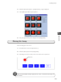
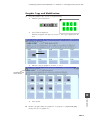
Copying the Lamp
Make four copies of lamp ① and complete them one by one.
1.
Click lamp ① (handles are shown).
Click [Multi Copy] icon in the tool bar. The [Multiple Copy] dialog is displayed.
2.
Set up as shown below and click [OK].
Line/Column
Interval
①②③
④⑤⑥
Direction:
X Distance: 5
Y Distance: 0
1st
09000-00
2nd
Operation
Memory INC
Lamp Memory
5
Quantity X: 4
Quantity Y: 1
Step: 1
3rd
4th
3.
Four lamps (the master lamp inclusive) are displayed.
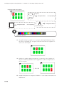
4.
Complete the 2nd, 3rd, and 4th lamps.
(1) Double-click the 2nd lamp. The [Lamp] dialog is displayed.
Open the [Main] tab window. Set up as shown below:
Division No.
Function
:0
: Normal
Lamp Memory : 09000-01
Draw Mode
: REP
Process cycle
: High Speed
(2) Click [Character] in the [Lamp] dialog. The [Character] tab window is
displayed.
(3) "1" is highlighted in the lamp. Key in "2".
5-11
Creating Lamps
(4) Click the [OK] button.
(5) For the 3rd and 4th lamps, follow the same steps.
Open the [Main] tab window and set up as shown below:
Division No.
:0
Function
: Normal
Lamp Memory : 09000-02 (3rd)
Draw Mode
Process cycle
09000-03 (4th)
: REP
: High Speed
Open the [Character] tab window and key in "3" for the 3rd lamp and "4" for
the 4th lamp.
Now screen No. 1 has been completed.
ZM-70 Operation Check
Save the created screen.
While referring to "Chapter 3 Screen Data Transference", transfer the created screen
data to ZM-70 and check that ZM-70 operates correctly.
Used memory
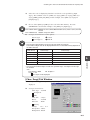
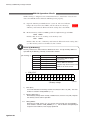
5-12
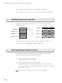
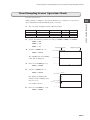
<Switch>
No. Output memory
1
M00000
2
M00001
3
M00002
4
M00003
5
None
Lamp memory
None
None
None
M00005
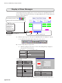
None
<Lamp>
No. Lamp memory
1
M00000
2
M00001
3
M00002
4
M00003
OFF color
Green
Green
Green
Green
OFF color
Blue
Blue
Blue
Blue
White
ON color
Yellow
Yellow
Yellow
Yellow
ON color
Red
Red
Red
Red
Yellow
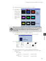
Creating Lamps
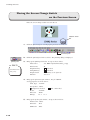
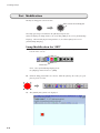
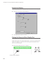
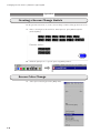
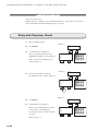
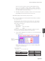
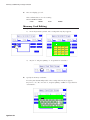
Screen Change Check
Screen No. 0 is displayed first.
Pressing the NEXT switch brings up screen No. 1.
Screen No. 0
Screen No. 1
5
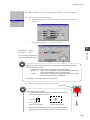
• Checking the screen currently being displayed in PLC
The Write Area "n+2" set up for [Write Area] in the [Comm. Parameter] dialog stores
the screen number currently being displayed.
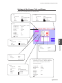
• Notes on changing the screen by using both switch and PLC
Change the screen with an external screen
number command from PLC first.
Afterwards, the screen change switch is used
to change screens.
Read area "n+2" = 5
When the first screen should be displayed again = External screen number command
with a command from PLC, the command is
invalid because the read area "n+2" (external
screen number command) still stores the first
While screens are switched internally,
"5" is still stored in the read area "n+2".
screen number. In such a case, when bit 14
of "n+1" is set (0 -> 1), the screen of the number
stored in the read area "n+2" is displayed.
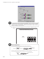
D000
D001
D002
5
To bring up screen No. 5 again
with an external command:
Screen forced switching (bit 14)
Screen No. 5
No. 2
No. 2
Screen No. 2
No. 0
No. 0
Screen No. 0
No. 3
15 14 13 12 11 10 09 08 07 06 05 04 03 02 01 00
D000
D001 0 1 0 0 0 0 0 0 0 0 0 0 0 0 0 0
5
D002 0 0 0
Set bit 14 (0 -> 1) of read area "n+1"
Screen No. 5
No. 2
5-13
Operation Check
ZM-80
Operation
• Changing the screen with an external command from PLC
Enter the desired screen number for the Read Area "n+2" (external screen number
command). The Read Area is set up for [Read Area] in the [Comm. Parameter] dialog
(displayed by selecting [System Setting] from the [Item] menu.)
Creating Lamps
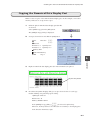
Checking Lamp Turning ON
1.
Press the AUTO switch.
1
M0000 ON
The switch lamp lights up.
Lamp ① lights up at the same time (M0000 is set).
AUTO
When the AUTO switch is released,
the lamp goes off automatically.
1
M0000 OFF
Lamp ① goes off at the same time (M0000 is reset).
AUTO
2.
Press the MANUAL switch.
The switch lamp lights up.
Lamp ② lights up at the same time (M0001 is set).
When the MANUAL switch is released,
M0001 ON
2
MANUAL
2
M0001 OFF
the lamp goes off automatically.
Lamp ② goes off the same time (M0001 is reset).
3.
Press the RUN switch.
The switch lamp lights up.
MANUAL
3
M0002 ON
RUN
Lamp ③ lights up at the same time (M0002 is set).
3
When the RUN switch is released,
the lamp goes off automatically.
Lamp ③ goes off at the same time (M0002 is reset).
5-14
RUN
M0002 OFF
Creating Lamps
4.
Lamp ④ lights up (M0003 is set).
STOP
4
When the STOP switch is released,
lamp ④ goes off (M0003 is reset).
5.
M0003 ON
4
Press the STOP switch.
M0003 OFF
STOP
Turn on the STOP switch lamp.
Set M0005 with a command from PLC.
The switch lamp lights up.
.....
(Refer to "(6)" on page 4-13.)
PLC Memory
M 0∼15
M0005
M16∼31
.....
5
Operation Check
ZM-80
Operation
STOP
PLC
5-15
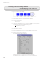
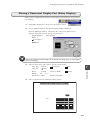
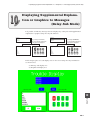
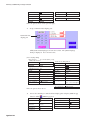
Creating PLC Numerical Data and Character Display Parts
6
Creating PLC Numerical Data
and Character Display Parts
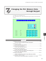
You will create the following screen including PLC numerical data and character
display parts.
6
Procedure
Operation
Procedure
1)
Setting up the [Num. Data Display] dialog
and placing the numerical data display part • • • • • • • • • • • • • • • • • • P6-3
2)
3)
Making copies of the part and their modification • • • • • • • • • • • • • • • P6-7
Setting up the [Char. Display] dialog
4)
and placing the character display part • • • • • • • • • • • • • • • • • • • • • P6-10
Making copies of the part and their modification • • • • • • • • • • • • • • • P6-13
Operation
Creating a New Screen
Open a new screen and place fixed texts.
1.
Click the [Next] icon to open a new screen.
6-1
Creating PLC Numerical Data and Character Display Parts
Create screen No. 2.
[Next] icon
2.
Select [Screen Setting] from the [Edit] menu. The [Screen Setting] dialog is
displayed.
Check white for [F (foreground)] and click [OK].
[Text] icon
3.
Click the [Text] icon in the draw tool bar.
4.
Key in "Numerical Data and Character Display". Set up text properties as shown
below and place it in the upper center of the screen.
Enlarge
X: 2 Y: 2
Foreground : Black
Background : White
Rotate
Direction
: Normal
: RGT
Create this title.
Transparent
Italic
Normal
5.
Click [Box] in the [Screen Drawing] dialog. Set up as shown below:
Foreground : Yellow
Background : Black
Frame Color : Black
Tile
Line Type
Paint
Frame
: No. 0
: No. 1
No. 0
No. 1
6.
Enclose "Numerical Data and Character Display" in a box.
7.
Move the box to the back of the title.
Click the [Select] icon and select the box (handles are shown). Click the [Move to
Back] icon.
[Select] icon
6-2
[Move to Back] icon
Creating PLC Numerical Data and Character Display Parts
8.
Key in "<Numerical data display>" and "<Character display>". Place them on the
left. Set up properties as shown below:
Enlarge
X: 1 Y: 1
Foreground : Black
Rotate
Direction
: Normal
: RGT
Transparent
Italic
Create these texts.
Normal
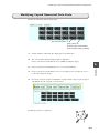
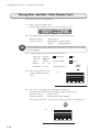
Creating Numerical Data Display Parts
Create the following numerical data display part.
Create this numerical data display part.
6
Operation
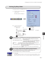
[Num. Display] Dialog
1.
Click [Num. Data Display] icon in the tool bar. The [Num. Display] dialog is
displayed.
[Num. Data Display] icon
Preview display
6-3
Creating PLC Numerical Data and Character Display Parts
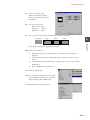
2.
Click the [Parts Select] button. [Num. Display List Parts_i.zmp] is displayed.
3.
Select [0007] and click the [Select] button.
Part No. 0007 appears in the preview display in the [Num. Display] dialog.
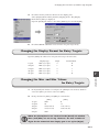
[Main] Tab Window
1.
In the [Num. Display] dialog, open the [Main] tab window. Check that "0" is
entered for [Division No.].
2.
The data stored in the assigned [Memory] is displayed on ZM-80. Enter
"D00200" in this example.
[Type] Tab Window
1.
Click [Type] in the [Num Display] dialog. The [Type] tab window is displayed.
2.
Select [No] for [Display Function].
"09200" entered for [Memory] in the previous step is displayed on the display part
on the screen.
3.
Enter "4" for [Digits] and enter "0" for [Decimal Point].
Depending on the [Display Type] selection,
the available data range varies
as shown on the right.
6-4
Type
Digits
DEC
1 ~ 10
HEX
1~8
OCT
1 ~ 11
BIN
1 ~ 32
Decimal point
0~9
Creating PLC Numerical Data and Character Display Parts
4.
Select the code for displaying data that is read in the code specified by [Input
Type]. The available codes are: [DEC (w/o sign)], [DEC (w/- sign)], [DEC (w/+
sign)], [HEX], [OCT] and [BIN]. In this example, select [DEC (w/o sign)] for
[Display Type].
5.
Choose either [BCD] or [DEC] for the code in the PLC memory. Because
SHARP PLC is used in this example, select [DEC] for [Input Type].
PLC in BCD format :OMRON C series; MITSUBISHI AnA/N series; FUJI H series, KOYO
SU/SG
PLC in BIN format : Models except the above
6.
Set up as shown below for other options:
Data Length
1-Word
Zero Suppress
Flush R
• One numerical data display part can occupy two words at maximum.
The number of digits that can be displayed from one- or two-word memory depends on
the code selected.
Code format
1-word range
2-word range
0~65535
0~4294967295
DEC (w/- sign)
-32768~32767
-2147483648~2147483647
DEC (w/+ sign)
-32768~+32767
-2147483648~+2147483647
HEX
0~FFFF
0~FFFFFFFF
OCT
0~177777
0~37777777777
BIN
0~1111111111111111 0~11111111111111111111111111111111
6
Operation
DEC (w/o sign)
• If the entered number of digits exceeds the specified range, extra digits from the right
are omitted.
<Ex.>
Data length: 1-Word
No. of digits: 3
1234 ---> 123
This figure is not displayed.
[Char. Prop] Tab Window
1.
Click [Char. Prop.] in the [Num Display] dialog. The [Char. Prop.] tab window is
displayed.
2.
Set up as shown below:
Char. Type : Normal
Transparent
Italic
Char. Size
: 1-Byte
Rotate
Direction
: Normal
: RGT
Spacing
Enlarge
X: 2
Y: 2
Foreground : White
Background : Black
6-5
Creating PLC Numerical Data and Character Display Parts
[Detail] Tab Window
1.
Click [Detail] in the [Num. Display] dialog. The [Detail] tab window is displayed.
2.
Uncheck the [Use Operation] and [Alarm] boxes.
3.
Select [High Speed] for [Process Cycle].
Placing the Numerical Data Display Part
Place the numerical data display part.
Click the [Place] button in the [Num. Display] dialog. A dotted box for numerical data
display area is displayed. Drag the box to the desired position and click the mouse.
(Refer to the following figure.)
The numerical data display part has been completed.
The part has been completed.
6-6
Creating PLC Numerical Data and Character Display Parts
Copying the Numerical Data Display Part
Make seventeen copies of the numerical data display part. In this example, consecutive
memory addresses are set up for the copies.
1.
Click the placed numerical data display part (handles
are shown).
Select [Multi Copy] from the [Edit] menu.
The [Multiple Copy] dialog is displayed.
2.
Set up as shown below and click the [OK] button.
Dot
Direction ①②③
④⑤⑥
Interval
X Distance: 8
Quantity X: 6
Y Distance: 8 Quantity Y: 3
Memory INC
Num. Data Memory
09200
Step: 1
6
Operation
3.
Eighteen numerical data display parts (the master inclusive) are placed.
18 parts are placed.
4.
Check that the [Num. Display] dialog is set up as shown below for each copy.
Double-clicking each part brings up the dialog.
<[Main] tab window>
Division No.: 0
Memory: 09200 ~ 09242
①②③
In the [Multiple Copy] dialog, [
] is selected for [Direction].
④⑤⑥
Therefore, memory addresses are allocated consecutively to the display parts
in the direction from left to right.
6-7
Creating PLC Numerical Data and Character Display Parts
Fig. 1
<[Type] tab window>
Display Function
: No
<[Char. Prop] tab window>
Char. Type
: Normal
Transparent
Italic
Digits
Decimal Point
:4
:0
Display Type
Input Type
: DEC (w/o sign)
: DEC
Char. Size
Rotate
: 1-Byte
: Normal
Data Length
Zero Suppress
: 1-Word
Flush R
Direction
Spacing
: RGT
Enlarge
Foreground
X: 2 Y: 2
: White
Background
: Black
<[Detail] tab window>
Use Operation
Alarm
Process Cycle
: High Speed
Memory data can be displayed on a computer screen as shown in Fig. 1.
Select [Display Environment] from the [Display] menu. The [Display Environment] dialog
is displayed.
Open the [Detail] tab window. Select [Memory] for [Detail] and click [OK].
Memory data is displayed
on the computer screen.
It is not necessary to allocate memory consecutively.
However, some PLC models can handle data more quickly when the
numbers are consecutive.
6-8
Creating PLC Numerical Data and Character Display Parts
Modifying Copied Numerical Data Parts
Modify the following numerical data parts.
[Display Type]: Choose [HEX].
[Decimal Point]: Enter "2".
[Digits]: Enter "6".
[Display Type]: Choose [DEC].
[Data Length]: Choose [2-Word]
1.
Double-click the numerical data display part for modification.
2.
The corresponding [Num. Display] dialog is displayed.
For the part allocated with 09236, choose [HEX] for [Display Type].
3.
For the part allocated with 09240, enter "2" for [Decimal Point].
4.
For the part allocated with 09242, enter "6" for [Digits], and consequently, choose
6
Operation
[2-Word] for [Data Length].
5.
Because the last part assigned with 09242 overlaps with the adjacent part assigned
with 09240, drag the last part as shown below:
Modification has been completed.
6-9
Creating PLC Numerical Data and Character Display Parts
Character Display
Create the following character display parts.
Create these character display parts.
[Char. Display] Dialog
1.
Click [Char. Display] icon in the tool bar. The [Char. Display] dialog is displayed.
[Char. Display] icon
Preview display
6-10
2.
Click the [Parts Select] button. [Char. Display List Parts_i.zmp] is displayed.
3.
Select [0007] and click the [Select] button.
Part No. 0007 appears in the preview display in the [Char. Display] dialog.
Creating PLC Numerical Data and Character Display Parts
[Main] Tab Window
1.
Check that "0" is entered for [Division No.].
2.
The data stored in the assigned [Memory] is displayed on ZM-80. Enter "09250"
in this example.
[Type] Tab Window
1.
Click [Type] in the [Char. Display] dialog. The [Type] tab window is displayed.
6
Operation
2.
Select [No] for [Display Function].
Only character display becomes valid.
3.
Enter "8" (4-word) for [Bytes].
4.
Choose [
Flush L].
6-11
Creating PLC Numerical Data and Character Display Parts
[Char. Prop] Tab Window
1.
Click [Char. Prop.] in the [Char. Display] dialog. The [Char. Prop.] tab window is
displayed.
2.
Set up as shown below:
Char. Type : Normal
Transparent
Italic
Rotate
Direction
: Normal
: RGT
Spacing
Enlarge
X: 2
Y: 2
Foreground : White
Background
: Black
[Detail] Tab Window
Click [Detail] in the [Char. Display] dialog. The [Detail] tab window is displayed.
Select [High Speed] for [Process Cycle].
The character display part has been completed.
6-12
Creating PLC Numerical Data and Character Display Parts
Placing a Character Display Part
Place a character display part.
Click the [Place] button in the [Char. Display] dialog. A dotted box for character
display area is displayed. Drag the box to the desired position and click the mouse.
Place the character display part here.
The character display part has been placed.
6
Operation
Copying the Character Display Part
Make a copy of the character display part.
1.
Click the character display part (handles are shown).
Select [Multi Copy] icon. The [Multiple Copy] dialog is displayed.
2.
Set up as shown below and click [OK].
Dot
Interval
Direction
X Distance: 0
Y Distance: 8
①②③
④⑤⑥
Quantity X: 1
Quantity Y: 2
Memory INC
Char. Data Memory
09250
3.
Step: 4
1 step = 1 word
8 bytes = 4 words
Two character display parts (the master inclusive) are placed.
6-13
Creating PLC Numerical Data and Character Display Parts
4.
Check that the [Char. Display] dialog is set up as shown below for the copy.
<[Main] tab window>
Division No. : 0
Memory
: 09260
Char. Type
Transparent
<[Type] tab window>
Display Function
Bytes
<[Char. Prop] tab window>
: No
:8
Flush L
<[Detail] tab window>
Process Cycle
: High Speed
Italic
Rotate
: Normal
: Normal
Direction
Spacing
: RGT
Enlarge
Foreground
X: 2 Y: 2
: White
Background
: Black
Screen No. 2 has been completed.
The following copy methods are available.
Copy by icons
Use the [Copy] and [Paste] icons in the edit tool bar.
[Copy] [Paste]
Copy by [CTRL]+dragging
Click the part/figure. While holding down the [CTRL] key, drag the part/figure to
the desired position and release the mouse. The copy is placed in the position.
Drag the switch while holding down the [CTRL] key.
[Multi copy]
To place copies at equal intervals
Select [Multi Copy] icon in the tool bar.or select
[Multi Copy] from the [Edit] menu.
The [Multiple Copy] dialog is displayed.
Set up the dialog for the desired number of copies
and their spacing.
(Refer to page 6-7.)
6-14
Creating PLC Numerical Data and Character Display Parts
ZM-70 Operation Check
Save the created screen.
While referring to "Chapter 3 Screen Data Transference", transfer the created screen
data to ZM-70 and check that ZM-70 operates correctly.
Used memory
<Character display>
No.
Memory Bytes
1
09220
8
2
09222
8
Decimal point
0
0
0
0
0
0
0
0
0
0
0
0
0
0
0
0
2
0
6
Operation
Operation Check
ZM-70
<Numerical data display>
No. Memory Code format Digits
1
09200 DEC (w/o sign) 4
2
09202 DEC (w/o sign) 4
3
09204 DEC (w/o sign) 4
4
09206 DEC (w/o sign) 4
5
09210 DEC (w/o sign) 4
6
09212 DEC (w/o sign) 4
7
09214 DEC (w/o sign) 4
8
09216 DEC (w/o sign) 4
9
09220 DEC (w/o sign) 4
10
09222 DEC (w/o sign) 4
11
09224 DEC (w/o sign) 4
12
09226 DEC (w/o sign) 4
13
09230 DEC (w/o sign) 4
14
09232 DEC (w/o sign) 4
15
09234 DEC (w/o sign) 4
16
09236 HEX
4
17
09240 DEC (w/o sign) 4
18
09242 DEC (w/o sign) 6
Writing Numerical Data from PLC
Open screen No. 2 "Numerical Data and Character Display" and check with the
following steps.
1.
By entering "0456" for "9200", "456" is displayed immediately.
SYSTEM
SYSTEM
Numerical Data and Character Display
<Numerical data display>
0
0
0
0
0
0
0
0
0
<Character display>
F 1
F 2
0
0
0
0
0 0.00
0
0
F 3
0
F 4
Numerical Data and Character Display
<Numerical data display>
456
0
0
0
0
0
0
0
0
F 1
F 2
0
0
0
0
0 0.00
0
0
F 5
<Character display>
F 6
F 7
2.
By entering "1234" for "9202", "1234" is displayed immediately.
3.
By entering "9999" for "9204", "9999" is displayed immediately.
4.
By entering "4EA0" for "9236", "4EA0" is displayed immediately.
F 3
0
F 4
F 5
F 6
F 7
6-15
Creating PLC Numerical Data and Character Display Parts
5.
By entering "1289" for "9240", "12.89" is displayed immediately.
6.
By entering "0" for "9242" or "1" for "9244", "65536" is displayed immediately.
Writing Characters from PLC
When data is to be displayed in characters, it may be easier to illustrate memory
allocation by bytes.
Memory "n"
Memory "n+1"
Memory "n+2"
Memory "n+3"
1st character LSB (0~7) A
2nd character MSB (8~15) B
C
3rd character
4th character
D
5th character
E
6th character
F
7th character
G
8th character
H
Memory "n"
B (42)
A (41)
2nd character 1st character
Memory "n+1"
D (44)
C (43)
2nd character 1st character
Memory "n+2"
F (46)
E (45)
2nd character 1st character
Memory "n+3"
H (48)
G (47)
2nd character 1st character
By entering "H4241" for "9220", "H4443" for "9222", "H4645" for "9224", and
"H4847" for "9226", "ABCDEFGH" is displayed immediately.
Placing Multiple Numerical Data
When displaying a greater amount of screen data, the display speed gets slower.
In such a case, the following methods should be effective.
1.
To increase the display speed for all data:
Allocate memory in consecutive number.
2.
To increase the display speed for the specified data:
For data which may be viewed slower when changed, choose [Low Speed] for
[Process Cycle]. Only for data which should be viewed in real time, choose [High
Speed] for [Process Cycle].
For details, refer to "Chapter 5 Screens" in the Reference Manual.
6-16
Changing the PLC Memory Data through Keypad
7
Changing the PLC Memory Data
through Keypad
You will create the following screen.
The desired values can be entered through the keypad to change the data in the PLC
memory.
7
Procedure
Operation
Procedure
1) Setting up the display environment • • • • • • • • • • • • • • • • • • • • • • • • • • P7-3
Set up the display environment before placing parts.
2) Placing the keypad • • • • • • • • • • • • • • • • • • • • • • • • • • • • • • • • • • • • • P7-4
Use the entry mode parts tool bar.
3) Placing the entry target parts. • • • • • • • • • • • • • • • • • • • • • • • • • • • • • P7-6
Use the entry mode parts tool bar.
4) Placing the entry display parts. • • • • • • • • • • • • • • • • • • • • • • • • • • • • • P7-9
Use the entry mode parts tool bar.
5) Placing the maximum and minimum value display parts • • • • • • • • • • • P7-10
Use the entry mode parts tool bar.
6) Setting up entry mode • • • • • • • • • • • • • • • • • • • • • • • • • • • • • • • • • • P7-11
Choose the [Detail] icon from the entry mode parts tool bar.
7) Checking the division number • • • • • • • • • • • • • • • • • • • • • • • • • • • • • P7-16
Check that the same division number is entered for 2, 4, 5, and 6.
7-1
Changing the PLC Memory Data through Keypad
Operation
Creating a Screen Change Switch
On the previous screen No. 2, create a screen change switch to bring up the next screen.
1.
Place a switch part as shown below. Enter [Screen: 3] for [Function] in the
[Switch] dialog.
2.
Click the [Next] icon to open the [Screen [3] Edit] window.
Screen Color Change
1.
7-2
Select [Screen Setting] from the [Edit] menu.
Changing the PLC Memory Data through Keypad
2.
Check blue for [F] in [Back Color]
and Click [OK].
The screen color is changed to blue.
Setting Up Display Environment
Set up the [Grid] tab window so that screen parts can be placed with ease.
Grids
Grids are small dots placed at regular intervals on the screen for facilitating drawing or aligning. [1-Byte (for
character)], [Switch (for switch)], [Mode (for overlap)] or [Free] can be selected for [Grid Type].
1.
Select [Display Environment] from the [Display] menu. The [Display
Environment] dialog is displayed.
7
Operation
2.
Open the [Grid] tab window and set up as shown below:
Grid Dsp.
ON Grid
Grid Color : White
Grid Type : Free
X Offset
X Pitch
:0
: 10
Y Offset: 0
Y Pitch : 10
Place switches on switch grids.
ON Grid
When this option is selected, a part/figure placed on the screen is snapped to the nearest grid.
However, an overlap part is moved by selecting [Mode] for [Grid Type] and a switch part is moved by selecting
[Switch] for [Grid Type], irrespective of the selection of [ON Grid].
(A switch part can be moved by selecting any other option for [Grid Type], but switch grids may be deviated. It
is recommended to select [Switch] to move switches.)
[ON grid] can be selected also from the pop-up menu which appears by right-clicking the mouse.
3.
Click [OK]. Grids are displayed on the screen.
7-3
Changing the PLC Memory Data through Keypad
Creating a Screen Title
1.
Click the [Text] icon in the draw tool bar. Key in "Numerical Data Entry Screen".
2.
Set up text properties and place the text as shown below:
Foreground : Red
Background : Light blue
Rotate
Direction
: Normal
: RGT
Enlarge X: 2
Enlarge Y: 2
Transparent
Normal
Italic
Numerical Data Entry Screen
Placing a Keypad
1.
Check that "0" is entered for [Division No.] at the top right of the screen.
When the above [Division No.] is set first, the same division number is automatically set
for the parts to be placed afterwards.
For information on the division number, refer to page 7-17.
7-4
2.
Click the [Entry Mode] icon in the tool bar.
3.
The entry mode parts tool bar is displayed on the right of the draw tool bar. Click
the [Keypad] icon on the extreme left.
Changing the PLC Memory Data through Keypad
4.
[Keypad List Parts_e.z7p] is displayed. Click [0001] and [Select].
5.
A keypad-size dotted box with cross cursor is displayed on the screen. Drag the
7
Operation
box and click the mouse in the position as shown below. The keypad is placed.
Numerical Data Entry Screen
Drag the cross cursor
and click it in the desired position.
7
8
9
△
4
5
6
▽
1
2
3
CLR
0
.
+-
ENT
When the keypad has been placed, it is grouped. To modify each switch position or
setting, click the keypad (handles are shown), and select [Ungroup] from the [Edit] menu
or click the [Ungroup] icon.
7-5
Changing the PLC Memory Data through Keypad
Placing a Numerical Data Display Part (Entry Target)
Place a numerical data display part to which data should be written.
Place this part.
Max. value
1234
Min. value
1234
Entered value 1234
Data 1
1234
Data 2
12
Data 3
123.4
Data 4
12.34
Data 5
1234
7
8
9
△
4
5
6
▽
1
2
3
CLR
0
.
+-
ENT
1.
Click the [Data Display] icon in the entry mode parts tool bar.
2.
The following pull-down menu is displayed. Choose [Numerical Data].
3.
The [Num. Display] dialog is displayed.
Open the [Main] tab window. Check that "0" is entered for [Division No.].
Open the [Type] tab window. Check that [Entry Target] is selected for [Display
Function], and "0" is entered for [Order].
Order
This option determines the order of the cursor moving between data display parts.
The cursor appears at the numerical data display part specified with "0" when the screen is opened.
7-6
Changing the PLC Memory Data through Keypad
4.
Click the [Parts Select] button. [Num. Display List] is displayed.
5.
Click [0001] and
make sure that
the [Save setting]
box is checked.
Click [Select].
Part No. 0001 is
displayed in the
[Num. Display]
dialog.
When the [Save setting] box is not checked, the previously set data
for [Division No.], [Display Function], [Memory], etc. are cleared.
This should be noted whenever a part is selected from [Num.
Display List].
6.
In the [Main] tab window, enter "09000" for [Memory].
7
Numerical data entered through the keypad is to be written to this address.
Operation
7.
Set up the [Char. Prop.] tab window as shown below:
Char. Type : Normal
Transparent
Char. Size
Rotate
: 1-Byte
: Normal
Enlarge
X: 1 Y: 1
Foreground : White
8.
Direction: RGT
Italic
Spacing
Background: Blue
Open the [Detail] tab window. Set up the maximum and minimum values.
Check the [Alarm] box so that [Max.] and [Min.] setting becomes valid. Set up as
shown below:
[Max.: 9999]
Max. Color
Foreground: Red
Background: Blue
[Min.: 0]
Min. Color
Foreground: Red
Background: Blue
7-7
Changing the PLC Memory Data through Keypad
If an entered value is not in the range from specified min. value to max. value, the value
is shown in the color selected for [Max. Color] or [Min. Color]. This function is valid only
when such a value is entered from PLC. When a value not within the range is entered
through the keypad, the entry is rejected.
9.
Place the numerical data display part as shown below by clicking the [Place]
button.
Numerical Data Entry Screen
1234
7
8
9
△
4
5
6
▽
1
2
3
CLR
0
.
+-
ENT
About transparency
For a numerical data or character display part, note the setting of [Transparent].
When a painted box is placed behind a part, the [Transparent] box must be checked.
Foreground color
Painted box
1234
Background color
With transparency
Foreground color
1234
Painted box
When a part consists of only foreground and background colors without a painted box (for example, part No.
0001 in [Num. Display List Parts_i.zmp]), the [Transparent] box must be unchecked.
Foreground color
1234
Without transparency
Background color
7-8
Only Foreground color
2222
1111
Changing the PLC Memory Data through Keypad
Placing a Numerical Display Part (Entry Display)
Place a part for displaying the data keyed in through the keypad (before being written to
the memory).
1.
Click [Entry Display] icon in the entry mode parts tool bar.
2.
Choose [Numerical Data]. The [Num. Display] dialog is displayed.
Open the [Main] tab window. Check that "0" is entered for [Division No.].
Open the [Type] tab window. Set up as shown below:
Display Function
Digits: 4
: Entry Display
Zero Suppress
Flush R
Specify the maximum number of digits for the placed entry target parts. In this example,
enter "4" for [Digits].
3.
Open the [Char. Prop.] tab window. Set up as shown below:
Char. Type : Normal
Char. Size : 1-Byte
: Normal
X: 1
7
Spacing
Direction: RGT
Y: 1
Foreground : White
4.
Italic
Operation
Rotate
Enlarge
Transparent
Background: Black
Place as shown below by clicking the [Place] button.
Numerical Data Entry Screen
1234
1234
7
8
9
△
4
5
6
▽
1
2
3
CLR
0
.
+-
ENT
7-9
Changing the PLC Memory Data through Keypad
Placing Max. and Min. Value Display Parts
Place max. and min. value display parts.
1.
Place a max. value display part.
Click the [Max. Display] icon in the entry mode parts tool bar.
2.
The [Num. Display] dialog is displayed. Set up as shown below:
[Main] tab window
Division No.: 0
[Type] tab window
Display Function: Max. Display
Digits: 4
Decimal Point: 0
Specify the maximum number of digits for the placed entry target parts. In this example,
enter "4" for [Digits].
3.
Set up the [Char. Prop.] tab window as shown below:
Char. Type : Normal
Char. Size : 1-Byte
Rotate
: Normal
Enlarge
X: 1 Y: 1
Foreground : Yellow
Transparent
Italic
Direction: RGT
Spacing
1234
Background: Red
1234
4.
Place the part as shown on the
1234
right by clicking the [Place]
button.
5.
7
8
9
△
4
5
6
▽
1
2
3
CLR
0
.
+-
ENT
Place a min. value display part. Click [Min. Display] icon.
Set up the [Num. Display] dialog and place the part as shown below:
[Main] tab window
[Type] tab window
Division No.: 0
Display function: Min. Display
[Char. Prop] tab window As same as the setting for the max. value display part
1234
1234
1234
1234
7-10
7
8
9
△
4
5
6
▽
1
2
3
CLR
0
.
+-
ENT
Changing the PLC Memory Data through Keypad
Setting Up Entry Mode
Set up entry mode for controlling the screen.
1.
Click [Detail] in the entry mode
parts tool bar.
The [Entry] dialog is displayed.
2.
Set up as shown below:
[Main] tab window
Division No.
Type
[Detail] tab window
:0
: Data Display
Command Memory : 09310
Info. Output Memory: $u16340
Reverse
Target Memory
Use Graphic
Default to 0
Process Cycle
: Low Speed
7
Direct
Type: Data Display --- Data display parts for entry targets are placed on the base screen.
Command Memory: 09310 -------This is used as a control memory for releasing the
keypad interlock, etc.
Info. Output Memory: $u16340 ---The selection order of the numerical data display part
currently selected by the cursor is written. (When it is
not necessary, select [Internal Mem.].)
Reverse =
This option determines whether to highlight the data display area (in
reverse video) currently selected as the entry target.
Target Memory: Direct = Data in the selected data display area is written directly to the
specified memory address.
Input Item Select: Internal = Up/Down switches on the screen are used to move the
cursor.
Bit 15 of the command memory (Writing enabled/disabled)
Writing is disabled by default for the keypad in the entry mode (any keys other than UP
and DOWN do not work) because bit 15 of the command memory is off.
To use the keypad, set bit 15 (= H8000) of the memory.
3.
Click [OK].
The [Entry] dialog is reduced to an icon and stored in the [Part] auxiliary tool box
in the lower left corner of the screen. This step completes setting up entry mode.
7-11
Operation
Internal
Input Item Select
ZM-30 Compatible
Changing the PLC Memory Data through Keypad
Copying the Numerical Display Part (Entry Target)
Make four copies of the numerical data display part to which data should be written.
1.
Click the numerical data display part (for which
[Entry Target] is selected for [Display Function]).
Handles are shown around it.
1234
2.
Select [Multi Copy] icon in the tool bar. The [Multiple Copy] dialog is displayed.
3.
Set up as shown below:
Dot
Interval
X Distance : 0
Y Distance : 14
Order INC
Direction
Quantity X
:1
Quantity Y
:5
Memory INC
Num. Data Memory 09310
4.
①②③
④⑤⑥
Step: 1
Click [OK]. Four copies are placed under the top
part vertically.
1234
1234
1234
1234
1234
7-12
Changing the PLC Memory Data through Keypad
5.
Check the memory addresses allocated to the display parts.
Select [Display Environment] from the [Display] menu. The [Display
Environment] dialog is displayed.
Open the [Detail] tab window. Check the [Memory] box and click [OK].
6.
Check that 09310 ~ 09320 are entered for the five parts respectively.
Changing the Display Format for Entry Targets
Open the [Main] tab window for each part and set up as shown below:
Display Type
Digits
Decimal Point
1st part
2nd part
3rd part
DEC (w/o sign)
DEC (w/o sign)
DEC (w/o sign)
4
2
4
0
0
1
4th part
5th part
DEC (w/o sign)
DEC (w/o sign)
4
4
2
0
7
Operation
Changing the Max. and Min. Values
for Entry Targets
1.
In the [Detail] tab window for each part, the [Alarm] box is checked, "9999" is
entered for [Max.], and "0" is entered for [Min.].
2.
Change the data for [Max.] and [Min.] in each window.
[Max.]
[Min.]
1st part
2nd part
9999
99
0
22
3rd part
4th part
5555(=555.5)
7777(=77.77)
1111(=111.1)
3333(=33.33)
5th part
9999
0
When the [Alarm] box is not checked in the [Detail] tab window,
[Max.] and [Min.] are not set up. However, the max. number of
digits for the numerical data display part is set up for [Digits].
7-13
Changing the PLC Memory Data through Keypad
Placing a Painted Box Behind the Parts
Drawing a Painted Box
Draw a painted box in the position as shown below:
Painted box
Numerical Data Entry Screen
Max. value
1234
Min. value
1234
Entered value 1234
1.
Click the [box] icon in the draw tool bar. The [Screen Drawing] dialog is
displayed.
2.
For drawing a painted box in this example, open the [Box] tab window and check
the [Paint] box. The following options appear in the window.
Paint type
3.
Line type
Set up as shown below:
Foreground : White
Background : Light blue
Frame Color : White
Tile
: No. 1 (2nd from the extreme left)
Line Type
7-14
: No. 1 (thick line: 2nd from the extreme left)
Changing the PLC Memory Data through Keypad
4.
Drag the cross cursor and draw a dotted box to enclose the placed parts on the
screen. A painted box is drawn as shown below:
Numerical Data Entry Screen
Draw a dotted box to enclose the parts.
5.
The parts are placed behind the painted box.
Click the [Select] icon and click the box (handles are shown). Click the [Move to
Back] icon. Now the parts appear on the painted box.
Click the [Move to Back] icon.
ta Entry Screen
7
ta Entry Screen
Operation
1234
1234
1234
Click the box (handles are shown).
The parts appear on the box.
7-15
Changing the PLC Memory Data through Keypad
Creating Texts
Create the following texts.
Numerical Data Entry Screen
Max. value
1234
Min. value
1234
Entered value 1234
Data 1
1234
Data 2
12
Data 3
123.4
Data 4
12.34
Data 5
1234
7
8
9
△
4
5
6
▽
1
2
3
CLR
0
.
+-
ENT
1.
Click the [Text] icon in the draw tool bar. The dialog for text entry is displayed.
2.
Set up as shown below and place the texts as shown in the above figure.
Prop.
Text "Max. value" "Min. value" "Entered value" "Data 1 (~5)"
Foreground
Red
Red
Blue
White
Enlarge X
1
1
1
1
Enlarge Y
1
1
1
1
Normal
Normal
Normal
Normal
RGT
RGT
RGT
RGT
checked
checked
checked
checked
unchecked
unchecked
unchecked
unchecked
Bold
Bold
Bold
Normal
Rotate
Direction
Transparent
Italic
Char. Type
Division Number Check
Check that the division number is set up correctly.
1.
7-16
Select [Display Environment] from the [Display] menu.
Changing the PLC Memory Data through Keypad
2.
The [Detail] tab window is displayed in the [Display Environment] dialog. Check
the [Div No.] box and click [OK].
3.
The division number is entered for each part on the screen.
Check that all parts on the screen and the icon in the [Part] auxiliary tool box have
the same division No. 0.
If not, correct data setting so that all division numbers are set to "0".
7
Operation
Set all division numbers to "0".
Division number
A maximum of 256 divisions(No. 0 to 255) can be set up for the base screen and each overlap respectively. You
can imagine that 256 transparent sheets are laid on top of each other.
When several parts (switch, numerical data display, display area) are combined to establish a function, such as
an entry mode, relay mode, and sampling mode, the parts must be set to the same division number.
Because the same division number is entered for the placed parts (keypad, max. value display part, etc.) in the
above example, they are linked with the entry mode and can function correctly.
The "Numerical Data Entry Screen" has been completed. Save the file and transfer the
screen data to ZM-70.
7-17
Changing the PLC Memory Data through Keypad
ZM-70 Operation Check
Opening Screen No. 3
1.
Connect ZM-70 to PLC, and start communication. Screen No. 0 including the bit
map data is displayed.
2.
Press the NEXT switch. Screen No. 1 is displayed. Press the NEXT switch on the
screen. Repeat these steps until screen No. 3 "Numerical Data Entry Screen" is
displayed.
The extreme right digit blinks.
Numerical Data Entry Screen
Cursor is displayed.
Max. value
9999
1234
Min. value
12340
Entered value 12340
0
Data 1
Data 2
7
8
9
△
4
5
6
▽
1
2
3
CLR
0
.
+-
ENT
0
Data 3
0.0
Data 4
0.00
Data 5
0
Releasing the Keypad Interlock
When the keypad interlock is on, the keys make an error sound (beep) when pressed
and do not work.
7-18
Changing the PLC Memory Data through Keypad
0
Data 1
Max. value
9999
Min. value
0
Entered value
0
7
8
9
△
4
5
6
▽
1
2
3
CLR
0
.
+-
ENT
0
Data 2
Data 3
0.0
Data 4
0.00
Data 5
0
Any keys in the enclosed area
do not work.
However, the upward and downward cursor keys are valid to move up/down the cursor.
By moving the cursor along the "Data" parts using the cursor keys, the max. and min.
values entered for each part are indicated.
0
Data 1
Data 2
Max. value
9999
Max. value
99
Min. value
0
Min. value
22
Entered value
0
Entered value
7
8
9
Data 3
0.0
Data 4
0.00
Data 5
0
5
6
▽
1
2
3
CLR
0
.
+-
ENT
key moves down the cursor.
Pi
!
Data 2
7
8
9
△
4
5
6
▽
1
2
3
CLR
0
.
+-
ENT
0
Data 3
0.0
Data 4
0.00
Data 5
0
7
The max. and min. values for the selected part are indicated.
To release the keypad interlock, follow these steps:
1.
Check that in the [Main] tab window of the [Entry] dialog, "D150" is entered for
[Command Memory]. Click the [Entry] icon in the [Part] auxiliary tool box and
click the [Detail] icon in the entry mode parts tool bar. The [Entry] dialog is
displayed. Check the [Command Memory].
09310 is used to release the keypad interlock.
7-19
Operation Check
ZM-80
Operation
Pressing the
4
0
Data 1
△
0
0
Changing the PLC Memory Data through Keypad
2.
Bit 15 of the memory D150 is the writing enabled/disabled bit. Set bit 15 (D150 =
H8000). Now the numerical keys and ENT keys of the keypad work.
Set bit 15 of D150.
D150
Max. value
9999
1234
Min. value
12340
Entered value 12340
0
Data 1
Data 2
7
8
9
△
4
5
6
▽
1
2
3
CLR
0
.
+-
ENT
0
Data 3
0.0
Data 4
0.00
Data 5
0
Pi
!
All keys on the keypad become valid.
3.
Locate the cursor on the "Data 1" part. Press "1" on the keypad. "1" is entered for
"Entered value".
Press "5". "15" is entered for "Entered value".
Max. value
9999
1234
Max. value
9999
1234
Min. value
12340
Min. value
12340
Entered value 12341
0
Data 1
Data 2
7
8
9
15
Entered value 1234
△
0
Data 3
0.0
Data 4
0.00
Data 5
0
0
Data 1
Data 2
7
8
9
4
5
6
△
▽
1
2
3
CLR
0
.
+-
ENT
0
4
5
6
▽
Data 3
0.0
1
2
3
CLR
Data 4
0.00
0
.
+-
ENT
Data 5
0
By pressing "5", "15" is entered for "Entered value".
4.
Press the ENT key. "15" is written to "Data 1". Check that "15" is written to
D160 (at [Memory] in the [Num. Display] dialog set up for "Data 1")
7-20
Changing the PLC Memory Data through Keypad
15
D160
Max. value
9999
1234
Min. value
12340
15
Entered value 1234
"15" is written to D160.
15
Data 1
7
8
9
△
4
5
6
▽
1
2
3
CLR
0
.
+-
ENT
0
Data 2
Data 3
0.0
Data 4
0.00
Data 5
0
Pi
!
By pressing the [ENT] key, "15" is written to "Data 1".
5.
Locate the cursor on the "Data 2" part. "Max. value" indicates "99" and "Min.
value" indicates "22".
Press "12" on the keypad. "12" is entered for "Entered value".
When one more key ("3" for example) is pressed, the key makes an error sound
(beep) and does not work because the maximum available digits have already been
entered.
Max. value
99
1234
Min. value
22
1234
7
15
Data 1
Data 2
7
8
9
△
4
5
6
▽
1
2
3
CLR
0
.
+-
ENT
ZM-80 Operation Check
Operation
12
Entered value 1234
0
Data 3
0.0
Data 4
0.00
Data 5
0
iPi
!
PiP
When a key is pressed while the maximum available digits
have already been entered, the key does not work.
6.
If the cursor is moved to the "Data 3" part before the [ENT] key is pressed, "Data
2" still indicates "0".
When "888.8" is keyed in and the [ENT] key is pressed while the cursor is located
on the "Data 3" part, the key makes an error sound (beep) and the entry is not
valid. Any value exceeding the maximum available value cannot be entered.
Press [CLR] key to reset "Entered value" and key in a value within the allowable
range.
7-21
Changing the PLC Memory Data through Keypad
Max. value
555.5
1234
Min. value
111.1
1234
Entered value 888.8
15
Data 1
7
8
9
△
4
5
6
▽
1
2
3
CLR
0
.
+-
0
Data 2
Data 3
0.0
Data 4
0.00
Data 5
0
ENT
i!
iP
PiP
If a value exceeding the max. available value is keyed in,
the [ENT] key is not valid.
Max. value
555.5
1234
Max. value
555.5
1234
Min. value
111.1
1234
Min. value
111.1
1234
0.0
Entered value
15
7
8
9
15
Data 1
△
0
0.0
0.00
0
5
6
▽
1
0
2
3
CLR
.
+-
ENT
Pi
!
7
8
9
△
4
5
6
▽
1
2
3
CLR
0
.
+-
ENT
0
Data 2
4
2.0
Entered value
Data 3
0.0
Data 4
0.00
Data 5
0
Pi
Press [CLR] key to reset "Entered value".
!
Key in a proper value.
About bit 14 (movement between entry items) of [Command
Memory]
It is recommended to set bit 14 (= H C000) when bit 15 of D150 (set up for [Command
Memory]) is set.
After a value is entered for an entry target part and the [ENT] key is pressed, the cursor
moves to the next part automatically.
Max. value
9999
1234
Max. value
99
1234
Min. value
12340
Min. value
22
1234
15
Entered value
0
7
8
9
15
△
0
7
8
9
△
4
5
6
▽
1
2
3
CLR
0
.
+-
ENT
0
0.0
0.00
0
4
5
6
▽
1
0
2
3
CLR
.
+-
ENT
When "1", "5" and [ENT] keys are pressed,
7-22
0
Entered value
0.0
0.00
Pi
!
0
the cursor moves to the next entry target part
automatically.
Changing the PLC Memory Data through Keypad
Memory for Entry Mode
The screen uses the following memory addresses:
Option
Address
Contents
Direction
Set in:
[Command Memory]
D150
Control memory for releasing
the keypad interlock, etc.
PLC -> ZM-70
[Memory]
D160
∼
D164
Memory to which values entered
through the keypad are written
ZM-70 -> PLC [Num. Display] dialog
[Entry] dialog
Questions and Answers
The following describes possible keypad problems and measures.
None of the keys on the keypad work.
--> The same division number may not be entered for the keys and the [Division
No.] in the [Entry] dialog. The same division number must be set up.
(Refer to page 7-16.)
Although the up/down cursor keys work, the numerical and [ENT] keys do not work.
--> Bit 15 (writing enabled/disabled bit) of [Command Memory] in the [Entry
Dialog] may not be set.
Setting bit 15 should release the keypad interlock.
7
The cursor does not appear on the screen.
--> A memory address may be entered for [Item Select Memory] in the [Screen
displayed only for the corresponding part. Delete the address entry.
[Item Select Memory] (in [Screen Setting] dialog)
When the entry mode is used, whether entry target parts on the base screen are valid is
controlled by [Item Select Memory].
Bits from 0 of the memory address "n" respectively correspond to the numbers entered
for [Order] (in the [Num. Display] dialog) for entry target parts. By setting a bit, the entry
target part of the corresponding [Order] number becomes valid for data entry and the
cursor is displayed.
Any entry target part having an [Order] number which corresponds to a reset bit becomes
invalid and the cursor is not displayed.
When bits of the [Item Select Memory] address
"n" are set as follows:
15 14 13 12 11 10 9
8
7
6
5
4
3
2
1
0
0
0
0
0
0
0
1
1
0
1
0
0
0
0
0
0
0
0.0
Ignored
Corresponding to [Order] numbers
7
8
9
△
4
5
6
▽
1
2
3
CLR
0
.
+-
ENT
0
0.00
0
Pi
!
The cursor moves between the entry target parts
as indicated by the arrows.
7-23
Operation Check
ZM-80
Operation
Setting] dialog for the screen.
When a memory address is entered for [Item Select Memory], the cursor is
Displaying the Keypad Only When Necessary (Multi-Overlap)
8
Displaying the Keypad Only When
Necessary (Multi-Overlap)
It is possible to display the keypad on the screen only when necessary.
Multi-O
Multi-Overlap
Data 1
445
Data 2
2990
Data 3
330
Data 4
15
Data 5
0
Data 1
Data 2
Pi
445
2990
7
8
4
5
1
2
0
.
Data 6
Data 7
Data 3
330
Data 8
Data 4
15
Data 9
Data 5
1234
0
!
9
△
1234
6
▽
3
CLR
+-
ENT
1234
1234
1234
Data 10
1234
9999
Max. value
Min. value
0
Entered value
0
You will create the following screen.
By pressing a numerical data display part, the hidden switch is activated to display the
keypad.
8
Outline
Operation
8-1
Displaying the Keypad Only When Necessary (Multi-Overlap)
Procedure
1) Setting up display environment • • • • • • • • • • • • • • • • • • • • • • • • • • • • P8-3
Set up the [Display Environment] dialog.
2) Setting up an overlap part in multi-overlap editing • • • • • • • • • • • • • • • • P8-5
Create an overlap to be called up.
3) Placing a keypad • • • • • • • • • • • • • • • • • • • • • • • • • • • • • • • • • • • • • • P8-7
Place a keypad using the entry mode parts tool bar in multi-overlap editing.
4) Placing entered value, max. value, and min. value display parts • • • • • • P8-8
Place them using the entry mode parts tool bar in multi-overlap editing.
5) Setting up entry mode • • • • • • • • • • • • • • • • • • • • • • • • • • • • • • • • • • • P8-9
Click the [Detail] icon in the entry mode parts tool bar in multi-overlap
editing.
6) Setting up multi-overlap in screen editing • • • • • • • • • • • • • • • • • • • • • P8-11
Set up the [Overlap Setting] dialog to call up the created overlap on the
screen.
7) Placing entry target parts in screen editing • • • • • • • • • • • • • • • • • • • • P8-12
Place the parts on the screen.
8) Placing the overlap call switches on the screen • • • • • • • • • • • • • • • • P8-15
Place them behind the numerical data display parts.
9) Division number check • • • • • • • • • • • • • • • • • • • • • • • • • • • • • • • • • P8-21
Check that the same division number is entered for 3, 4 and 5.
Operation
Creating a Screen Change Switch
Create the following screen change switch.
8-2
1.
Place the switch part as shown below. Enter [Screen: 4] for [Function] in the
[Switch] dialog.
2.
Click the [Next] icon to open the [Screen [4] Edit] window.
Displaying the Keypad Only When Necessary (Multi-Overlap)
Screen Color and Display Environment Setting
1.
Select [Screen Setting] from the [Edit] menu. Check green for [F] in [Back Color]
and Click [OK].
The screen color is changed to green.
2.
Select [Display Environment] from the [Display] menu. The [Display
Environment] dialog is displayed.
3.
Open the [Grid] tab window. Set up as shown below and click [OK].
Grid Dsp.
ON Grid
Grid Color : Purple
Grid Type : Free
X Offset
X Pitch
:0
:5
Y Offset : 0
Y Pitch : 5
Place switches on switch grids.
The purple grids are displayed on the screen.
Creating a Screen Title
Click [Text] icon in the draw tool bar. Key in "Multi-Overlap".
2.
Set up text properties as shown below:
Foreground : Red
Background : Black
Rotate
Direction
: Normal
: RGT
Enlarge X
Enlarge Y
8
Operation
1.
:2
:2
Italic
Shadow
Multi-Overlap
3.
Draw a box to be placed behind the title.
Click the [Box] icon in the draw tool bar. The following dialog is displayed.
8-3
Displaying the Keypad Only When Necessary (Multi-Overlap)
4.
Set up properties as shown below:
Foreground : White
Background : Black
Frame Color : Black
Tile
Line Type
5.
Paint
Frame
: No. 0 (extreme left)
: No. 0 (extreme left: solid line)
Draw a painted box and cover the title.
Multi-Overlap
6.
Click the [Select] icon and click the box (handles are shown).
Click the [Move to Back] icon. The title appears on the box.
Multi-Overlap
7.
Copy the box.
Click the box (handles are shown). While holding down the [CTRL] key, drag the
box. The copy box is displayed in the dragged position.
Multi-Overlap
Drag the box while holding down the [CTRL] key.
Multi-Overlap
The copy box is displayed.
8-4
Displaying the Keypad Only When Necessary (Multi-Overlap)
8.
Double-click the copy box or click it (handles are shown). Click the [Detail/Prop.
Change] icon. The [Prop. Change] dialog is displayed.
Check black for [Foreground].
9.
While handles are shown around the box, click the [Move to Back] icon. Place the
box as shown below. The copy box is placed like a shadow of the original box.
Multi-Overlap
This step completes drawing the screen title.
Creating an Overlap
Create an overlap to be called up.
8
Operation
1.
Select [Multi-Overlap] from the [Item] menu.
8-5
Displaying the Keypad Only When Necessary (Multi-Overlap)
2.
The [Multi-Overlap] dialog is displayed. Check that "0" is entered and click the
[OK].
3.
The [Multi Overlap [0] Edit] window is opened. Click the [Overlap] icon in the
tool bar.
4.
The [Overlap (Normal)] dialog is displayed. Click the [Parts Select] button and
select the [0002] part.
5.
Set up as shown below:
Use System Button
Frame Type : Paint
Frame Prop. : Yellow
Area Prop. Foreground
Tile
: Green
Background : White
: No. 1 (2nd from the left)
Continue reading PLC memory when set to OFF
8-6
Displaying the Keypad Only When Necessary (Multi-Overlap)
6.
Click [Place]. A dotted box with cross cursor is displayed. Place the box on the
screen by clicking it. Adjust it to the keypad size.
Placing a Keypad
1.
In the [Multi Overlap [0] Edit] window, in which the overlap part is placed, rightclick the mouse.
The following pop-up menu is displayed.
8
Operation
2.
Select [Overlap 0]. Now the editing layer is limited within the overlap part and
parts placement or drawing is allowed only on the part. The tool bar as enclosed
below becomes valid.
3.
Check that "0" is entered for [Division No.] at the top right of the screen. Click
the [Entry Mode] icon. Click the [Keypad] icon in the entry mode parts tool bar.
8-7
Displaying the Keypad Only When Necessary (Multi-Overlap)
If the entry mode parts tool bar is not displayed entirely, click the outside of any icon and
drag the tool bar to the desired position on the screen.
If entry mode parts tool bar is hidden,
click the outside of any icon and drag.
The entry mode parts tool bar is displayed independently.
4.
Click [0002] and place the keypad as shown below:
Placing Numerical Data Display Parts (Entry Display)
Place the numerical data display parts for entered value, max. value, and min. value on
the overlap.
1.
Click [Entry Display] icon in the entry mode parts tool bar.
Select [Numerical Data]. The [Num. Display] dialog is displayed. Select the
[0001] part. Set up properties as shown below and place it on the screen.
[Main] tab window
Division No.: 0
[Type] tab window
[Char. Prop] tab window
0
.
+-
ENT
Display function: Entry Display
Char. Type: Normal
Transparent
Char. Size
1-Byte
Rotate: Normal
Spacing
Enlarge X: 1 Y: 1
Foreground: Blue
1234
8-8
Digits: 4
Italic
Direction: RGT
Background: Yellow
Displaying the Keypad Only When Necessary (Multi-Overlap)
2.
Also place the max. value and min. value display parts following the same steps.
Click the [Max. Display] icon and [Min. Display] icon in the entry mode parts tool
bar respectively and set up as shown below:
[Main] tab window
Division No.: 0
[Type] tab window
Display function: Max. or Min. Display
Digits: 4
Decimal Point: 0
Display Type: DEC (w/o sign)
Char. Type: Normal
[Char. Prop] tab window
Transparent
Char. Size
1-Byte
Italic
Rotate: Normal
Direction: RGT
Spacing: unchecked
Enlarge X: 1 Y: 1
Foreground: Purple
0
.
+-
Background: Yellow
ENT
Max. value display
1234
1234
Min. value display
1234
Setting Up Entry Mode
Set up the control data for the keypad placed on the overlap.
8
1.
Operation
Click the [Detail] icon
in the entry mode parts tool bar.
The [Entry] dialog is displayed.
8-9
Displaying the Keypad Only When Necessary (Multi-Overlap)
2.
Set up as shown below:
[Main] tab window
[Detail] tab window
Division No.: 0
Type: Data Display
Use Graphic
Default to 0
Command Memory: 09310
Info. Output Memory: $u16340
Reverse
Target Memory
Process Cycle: Low Speed
Direct
Internal
Input Item Select
ZM-30 Compatible
3.
Click [OK].
The [Entry] icon is stored in the [Part] auxiliary tool box in the lower left corner.
Placing Texts on the Overlap
Place the following texts on the overlap.
0
1.
.
+-
ENT
Max. value
1234
Min. value
1234
Entered value
1234
Click the [Text] in the draw tool bar.
The dialog for text entry is displayed.
2.
Key in the texts and set up properties as shown below:
Prop.
Text "Max. value" "Min. value" "Entered value"
Red
Foreground
White
Background
1
Enlarge X
1
Enlarge Y
Normal
Rotate
RGT
Direction
unchecked
Italic
Shadow
Char. Type
Red
White
1
1
Normal
RGT
unchecked
Shadow
Green
Blue
1
1
Normal
RGT
unchecked
Shadow
Place the texts on the overlap as shown in the above figure.
8-10
Displaying the Keypad Only When Necessary (Multi-Overlap)
[Overlap Setting] Dialog
Return to the [Screen Edit] window and set up the [Overlap Setting] dialog for calling
up the overlap.
1.
Click the "x" (close) button in the [Multi Overlap [0] Edit] window.
The [Screen [4] Edit] window is displayed.
[Close] button
2.
Click the [Overlap] icon in the tool bar. The [Overlap Setting] dialog is displayed.
8
Operation
3.
Click the [No. 0 Overlap] box. The following options are displayed. Click
[Multi].
8-11
Displaying the Keypad Only When Necessary (Multi-Overlap)
4.
The [Overlap (Multi)] dialog is
displayed.
5.
Set up as shown below:
Overlap No.: 0
Item Select
Command
Internal
Memory: $u16340
6.
Click [OK].
The [Overlap] icon is stored in the [Part] auxiliary tool box in the lower left corner
of the screen.
The setting to call up the overlap on the screen has been completed.
Placing a Numerical Data Display Part (Entry Target)
Place a numerical data display part to which data entered through the keypad should be
written.
1.
Click the [Num. Data Display] icon in the tool bar.
2.
The [Num. Display] dialog is displayed. Click [Part Select]. Select [0001] from
the list.
3.
Set up as shown below:
[Main]
Memory: D180
[Type]
Display Function: Entry Target
Order: 0
Digits: 4
Decimal Point: 0
Display Type: DEC (w/o sign)
Entry Type: DEC
Data Length: 1-Word
[Char. Prop]
Zero Suppress : Flush R
Char. Type: Normal
Transparent
Rotate: Normal
Foreground: White
8-12
Italic
Direction: RGT
Char. Size
1-Byte
Enlarge X: 1 Y:1
Background: Green
Displaying the Keypad Only When Necessary (Multi-Overlap)
[Detail]
Alarm
Max.: 9999
For checking/
unchecking the
[Alarm] box, refer
to page 7-13.
Min.: 0
Max. Color
Foreground
: Red
Min. Color
Background
Foreground
: Green
: Red
Background
: Green
Process Cycle: High Speed
4.
Click [Place]. A dotted box with cross cursor is displayed on the screen. Place it
as shown below.
Multi-Overlap
1234
Placing an Overlap Call (Hidden) Switch
To bring up the keypad when any numerical data display part is pressed, place an
overlap call switch behind each part. Place one switch with the following steps.
Multi-O
445
Data 1
2990
Data 2
Multi-Overlap
Data 1
Data 2
445
2990
7
8
4
5
1
2
0
.
Data 6
Data 7
Data 3
330
Data 3
330
Data 8
Data 4
15
Data 4
15
Data 9
Data 5
0
Data 5
1234
0
!
△
6
▽
3
CLR
+-
ENT
1234
1234
1234
8
Data 10
1234
9999
Max. value
Min. value
0
Entered value
0
Operation
Pi
9
1234
Place an overlap call switch
behind the part.
1.
Click the [Switch] icon in the tool bar.
The [Switch] dialog is displayed.
8-13
Displaying the Keypad Only When Necessary (Multi-Overlap)
2.
Click the [Parts Select] button and select [0000]. The [Switch] dialog is displayed
again.
3.
Click the [Change] button at [Function] in the [Main] tab window. The [Switch
Function] dialog is displayed.
Select [Multi-Overlap] and enter "0" for [Overlap No.] and [Multi-Overlap No.].
Click [OK].
4.
Open the [Color] tab window and
set up as shown below:
ON Color : Purple
OFF Color : Green
Frame Type : No Frame
5.
Click [Place] and place the switch over the top numerical data display part.
The numerical data display part is under the switch.
Multi-Overlap
1234
The numerical data display par t is hidden.
6.
Click the switch (handles are shown). Click the [Move to Back] icon to display
the part on the switch.
Select the switch
(handles are shown).
Click the [Move to Back] icon.
1234
8-14
The numerical data display par t
appears on the switch.
1234
Displaying the Keypad Only When Necessary (Multi-Overlap)
Copying the Numerical Data Display Part
and the Overlap Call Switch
Make nine copies of both the numerical data display part and the overlap call switch.
1.
Copy the numerical data display part.
Click the numerical data display part. Select [Multi Copy] from the [Edit] menu.
The [Multiple Copy] dialog is displayed.
Multi-Overlap
1234
2.
Set up as shown below:
Dot
Interval
Direction
X Distance : 0
Y Distance : 24
①②③
④⑤⑥
Quantity X
Quantity Y
:1
:6
Order INC
Memory INC
Num. Data Memory: D180
3.
Step: 1
Click [OK]. The copy parts are displayed on the screen.
8
Multi-Overlap
Operation
1234
1234
1234
1234
1234
1234
4.
Click the bottom part and move it as shown below:
8-15
Displaying the Keypad Only When Necessary (Multi-Overlap)
Multi-Overlap
1234
1234
1234
1234
1234
1234
5.
Click the moved part (handles are shown). Select [Multi Copy] icon in the tool
bar. The [Multiple Copy] dialog is displayed. Set up as shown below:
Dot
Interval
Direction
X Distance : 0
Y Distance : 24
①②③
④⑤⑥
Quantity X
Quantity Y
:1
:5
Order INC
Memory INC
Num. Data Memory: D185
6.
Step: 1
Click [OK].
The copies are displayed as shown below:
Multi-Overlap
8-16
1234
1234
1234
1234
1234
1234
1234
1234
1234
1234
Displaying the Keypad Only When Necessary (Multi-Overlap)
7.
Make nine copies of the overlap call switch.
Click the switch (handles are shown) and open the [Multiple Copy] dialog.
Select the switch.
1234
8.
Set up as below and click [OK].
Dot
Direction
①②③
④⑤⑥
Interval
X Distance : 3
Quantity X
:2
Y Distance : 3
Quantity Y
:5
Multi-Overlap
9.
1234
1234
1234
1234
1234
1234
1234
1234
1234
1234
Place five copy switches over the respective numerical data display parts on the
right.
8
Multi-Overlap
1234
1234
1234
1234
1234
1234
1234
1234
1234
Operation
1234
10. Move each switch behind the part using the [Move to Back] icon.
8-17
Displaying the Keypad Only When Necessary (Multi-Overlap)
Placing the Overlap
It is possible to specify the position of the overlap, which is displayed by pressing an
overlap call switch.
1.
Click the top switch on the left and click the [Detail/Prop. Setting] icon (or,
double-click the switch). The [Switch] dialog is displayed.
Multi-
1234
1234
1234
1234
1234
8-18
2.
Check that "Multi-Overlap: O:0 M:0" is entered for [Function] in the [Main] tab
window. Open the [Detail] tab window.
3.
The [Define MLIB Placement] box is checked. Click the [Placement] button.
The [Switch] dialog disappears, and the "OVLP" cursor appears on the screen.
Displaying the Keypad Only When Necessary (Multi-Overlap)
4.
Click the "OVLP" cursor in the desired position, in which the top left corner of the
overlap part is located. "MLIB" appears in the position, and the [Switch] dialog is
displayed.
"MLIB" appears here when the switch for
[Function: Multi-overlap] is placed on the screen.
"MLIB" is displayed in the position.
MLIB
Multi-Overla
Multi-Overla
MLIB
1234
1234
1234
1234
1234
1234
1234
Click the mouse
in the desired position.
1234
1234
1234
5.
Click [OK].
6.
Specify the overlap positions for the remaining nine switches with the same steps
using the [Placement] button in the [Detail] tab window.
Drawing on the Screen
8
Draw texts, boxes, and lines on the screen as shown below:
Operation
Box and line
Multi-Overlap
Data 1
1234
Data 6
1234
Data 2
1234
Data 7
1234
Data 3
1234
Data 8
1234
Data 4
1234
Data 9
1234
Data 5
1234
Data 10
1234
Text
8-19
Displaying the Keypad Only When Necessary (Multi-Overlap)
1.
Click the [Text] icon in the draw tool bar. Enter the desired texts and place them.
Set up properties as shown below:
Prop.
Text "Data 1 (~ 10)"
Foreground
White
Enlarge X
1
Enlarge Y
1
Rotate
Normal
Direction
RGT
Transparent
Italic
Char. Type
2.
checked
unchecked
Normal
Right-click the mouse to bring up the pop-up menu.
Uncheck [ON Grid].
Click here to delete the check mark.
3.
Draw the following table using the [Line] and [Box] icons in the draw tool bar.
Set up properties as shown below:
Vertical line
Color
Line Type
Horizontal line
Color
: White
: No. 1 (thick line)
Box
Foreground : White
Line Type : No. 0 (solid line)
Paint
: White
Line Type
: No. 0 (solid line)
Ver tical line
Multi-Overlap
Box
Horizontal line
Data 1
1234
Data 6
1234
Data 2
1234
Data 7
1234
Data 3
1234
Data 8
1234
Data 4
1234
Data 9
1234
Data 5
1234
Data 10
1234
When drawing vertical or horizontal lines, drag the mouse while holding down the
[SHIFT] key. Lines can be drawn straight.
8-20
Displaying the Keypad Only When Necessary (Multi-Overlap)
Division Number Check
Check that the division number is set up correctly.
1.
Select [Multi-Overlap] from the [Item] menu and open the [Multi Overlap [0]
Edit] window.
2.
Select [Display Environment] from the [Display] menu. The [Display
Environment] dialog is displayed. Check the [Div No.] box for [Detail] and click
[OK].
3.
The division number (<0>) is entered for each part on the overlap.
Check that all parts and the icon in the [Part] auxiliary tool box have the same
division No. 0.
8
Operation
The same division number
must be set up.
The overlap has been completed.
Save the file and transfer the data to ZM-80.
8-21
Displaying the Keypad Only When Necessary (Multi-Overlap)
ZM-70 Operation Check
Opening Screen No. 4
1.
Connect ZM-70 and PLC, and start communication. Screen No. 0 including the
bit map data is displayed.
2.
Press the NEXT switch. Screen No. 1 is displayed. Press the NEXT switch on the
screen. Repeat this procedure until screen No. 4 "Multi-Overlap Screen" is
displayed.
Multi-Overlap
Data 1
0
Data 6
0
Data 2
0
Data 7
0
Data 3
0
Data 8
0
Data 4
0
Data 9
0
Data 5
0
Data 10
0
Calling Up the Overlap
1.
Press any numerical data display part. The overlap is displayed and the cursor is
placed on the pressed part.
8-22
Displaying the Keypad Only When Necessary (Multi-Overlap)
Multi-O
Multi-Overlap
Data 1
0
Data 2
0
Data 3
0
Data 4
0
Data 5
0
Data 1
Data 2
Pi
2.
7
8
4
5
1
2
0
.
Data 6
0
Data 7
0
Data 3
0
Data 8
Data 4
0
Data 9
Data 5
1234
0
!
9
△
1234
6
▽
3
CLR
+-
ENT
1234
1234
1234
Data 10
1234
9999
Max. value
Min. value
0
Entered value
0
Press the top left corner of the overlap. The overlap frame blinks. By pressing a
different position on the screen, the overlap is moved into position.
By clicking here,
the overlap frame blinks.
Click the desired position.
The overlap moves.
Multi-Overla
Multi-Overlap
7
8
4
5
1
2
0
.
Data 1
0
Data 6
Data 2
0
Data 7
Data 3
0
Data 8
0
Data 9
Data 4
Data 5
8
9
4
5
6
▽
2
3
CLR
9
△
1
6
▽
0
3
CLR
+-
ENT
1234
1234
1234
1234
Data 10
1234
9999
Max. value
1234
0
7
Min. value
0
Entered value
0
Data 1
△
0
.
+-
Data 2
Data 3
Max. value
Data
4
Min. value
Entered value
Data 5
ENT
Data 6
0
Data 7
0
Data 8
00
Data 9
9999
0
1234
0
Data 10
8
To delete the overlap, double-press the top left corner of the overlap (because the
system button is activated).
Double-press here
to delete the overlap.
Multi-Overla
7
8
9
4
5
6
▽
1
2
3
CLR
Data 1
0
.
Data 2
Data 3
Max. value
Data
4
Min. value
Entered value
Data 5
Multi-Overla
△
Data 6
Data 1
0
Data 6
0
Data 7
Data 2
0
Data 7
0
Data 8
Data 3
0
Data 8
00
Data 9
Data 4
0
Data 9
Data 10
Data 5
0
Data 10
0
+-
ENT
9999
0
1234
0
8-23
Operation Check
ZM-80
Operation
3.
Displaying the Keypad Only When Necessary (Multi-Overlap)
Releasing the Keypad Interlock
1.
When the numerical data display part of "Data 1" is pressed, the overlap appears
on the right and the cursor is displayed on the part.
Multi-Overlap
Multi-O
Pi
!
7
8
4
5
1
2
0
.
9
△
Data 1
0
Data 1
0
Data 6
Data 2
0
Data 2
0
Data 7
Data 3
0
Data 3
0
Data 8
Data 4
0
Data 4
0
Data 9
Data 5
0
Data 5
0
Data 10
1234
9999
Max. value
2.
1234
6
▽
3
CLR
+-
ENT
1234
1234
1234
Min. value
0
Entered value
0
When any numerical key or the ENT key is pressed, the key makes an error sound
(beep) and does not work because the keypad interlock is on.
For the overlap, "D170" is entered for [Command Memory] in the [Entry] dialog.
Set bit 15 of D170 (= H8000). Now the keypad interlock is released.
Set bit 15 of D170.
D170
3.
Press "33" on the keypad. "33" is indicated at "Entered value".
Multi-Overlap
Data 1
Data 2
8-24
0
0
7
8
4
5
1
2
0
.
Data 6
Data 7
Multi-Overlap
9
△
6
▽
3
CLR
+-
ENT
1234
0
1234
Data 3
0
Data 8
Data 4
0
Data 9
Data 5
0
Data 10
1234
9999
Max. value
1234
1234
!
Pi i !
P
0
7
8
4
5
1
2
0
.
Data 6
Data 7
9
△
1234
6
▽
3
CLR
+-
ENT
1234
0
Data 8
0
Data 9
0
Data 10
1234
9999
Max. value
1234
1234
Min. value
0
Min. value
Entered value
0
Entered value
0
33
Displaying the Keypad Only When Necessary (Multi-Overlap)
4.
Press the ENT key. The overlap disappears and "33" is written to "Data 1".
Check that "33" is written to D180 (the address set for [Memory] in the [Num.
Display] dialog for Data 1) in the PLC memory.
Press the ENT key.
The overlap disappears and "33" is written to D180.
Multi-Overlap
Data 1
7
8
4
5
1
2
0
.
Data 6
0
Multi-Overlap
9
△
6
▽
3
CLR
+-
ENT
1234
Data 2
0
Data 7
Data 3
0
Data 8
Data 4
0
Data 9
Data 5
0
Data 10
1234
9999
Max. value
1234
1234
1234
Min. value
Entered value
Pi
33
Data 6
0
0
Data 7
0
0
Data 8
0
0
Data 9
0
0
Data 10
0
!
0
33
Values can be written to the other data display parts with the same steps.
Memory for Entry Mode
The screen uses the following memory addresses:
Option
Address
Contents
Direction
Set in:
[Command Memory]
D170
Control memory for releasing
the keypad interlock, etc.
PLC -> ZM-70
[Entry] dialog
(in overlap editing)
[Memory]
D180
∼
D189
Memory to which values entered
through the keypad are written
ZM-70 -> PLC
[Num. Display] dialog
(in screen editing)
8
Operation Check
ZM-80
Operation
Questions and Answers
The following describes possible keypad problems on the overlap and measures.
The cursor is displayed even though the overlap is not called.
--> [Entry] dialog should be set up only for the overlap, but it may have been set
also in the screen edit window.
If the [Entry] icon is stored in the auxiliary tool box also on the screen, the
[Entry] dialog has been set up. Delete it.
8-25
Displaying Messages by Setting/Resetting Bits (Relay Mode)
9
Displaying Messages by Setting/
Resetting Bits (Relay Mode)
The following ways are available to display messages on the screen.
Messages are displayed or erased by setting or resetting of bits.
Messages are linked with bits in the PLC memory.
Relay mode When a bit is set, its corresponding message is displayed.
Supplemental
display function
Sub-display (Relay-sub)
Screen-call
Supplemental messages or
graphics are displayed.
A screen block is called.
Messages are displayed by specifying the numbers.
Message mode
Page mode
Direct mode
As many consecutive messages
as the number of lines (Y size) are displayed.
As many messages as the number of lines (Y size)
are displayed by specifying each message number.
The messages to be displayed are set up in the message edit window.
In this chapter, you will create the following screen in relay mode.
9
Outline
Operation
9-1
Displaying Messages by Setting/Resetting Bits (Relay Mode)
Procedure
1) Registering messages • • • • • • • • • • • • • • • • • • • • • • • • • • • • • • • • • • • P9-3
2) Selecting relay mode • • • • • • • • • • • • • • • • • • • • • • • • • • • • • • • • • • • P9-6
3) Setting up the [Relay] dialog • • • • • • • • • • • • • • • • • • • • • • • • • • • • • • P9-7
4) Setting up a message display area part • • • • • • • • • • • • • • • • • • • • • • P9-10
5) Creating the Roll Up and Roll Down switches • • • • • • • • • • • • • • • • • • P9-12
6) Division number check • • • • • • • • • • • • • • • • • • • • • • • • • • • • • • • • • P9-14
Operation
Creating a New Screen
Create and place the NEXT switch to bring up the next screen on screen No. 4. Open a
new screen and place the fixed text.
1.
Place a switch part on screen No. 4 as shown below. In the [Switch] dialog, enter
[Screen: 5] for [Function].
2.
Click the [Next] icon to open the new screen No. 5.
3.
Select [Screen Setting] from the [Edit] menu. In the [Screen Setting] dialog,
check black for [F (foreground)]. Click [OK].
[Next] icon
4.
Select [Display Environment] from the [Display] menu. Open the [Grid] tab
window and uncheck the [Grid Dsp.] box. Also uncheck the [ON Grid] box if it is
checked. Click [OK].
Uncheck this check box.
9-2
Displaying Messages by Setting/Resetting Bits (Relay Mode)
5.
Check that "0" is entered for [Division No.] at the top right of the screen.
6.
Key in "Trouble Display". Set up properties as shown below and place the title in
the center of the screen.
Foreground: White
Enlarge X: 3
Direction: RGT
Transparent
Enlarge Y: 3
Rotate: Normal
Message Registration
It is necessary to register the messages to be displayed on the screen. Open the
[Message Edit] window.
Set up messages to be displayed
in this area.
1.
Select [Message] from the [Item] menu. The [Message] dialog is displayed. Enter
"0" (group number) and click the [OK] button.
Group No.
9
Operation
The message editing area is divided into 24 groups, each of which can contain a
maximum of 256 message lines (maximum available lines: 6144 lines). In message
editing, a maximum of 80 one-byte characters or 40 two-byte characters can be
registered per line.
9-3
Displaying Messages by Setting/Resetting Bits (Relay Mode)
2.
The [Message [0] Edit] window is displayed.
Group No.
Cursor
[Next] icon
Click this to bring up the next
group number window.
Indicates the cursor position.
3.
Enter messages using alphabets in this example. Start to enter them from line No.
0. Registration is made upon entry. Press the return key to move the cursor to the
next line.
Line No.
0
1
2
3
4
5
6
7
9-4
Message
AAAAAAAA
BBBBBBBB
CCCCCCCC
DDDDDDDD
EEEEEEEE
FFFFFFFF
GGGGGGGG
HHHHHHHH
Displaying Messages by Setting/Resetting Bits (Relay Mode)
4.
To close the [Message [0] Edit] window, click [X](close) or select [Close] from
[File] the pull-down menu.
Or, click this button.
The [Message Edit] window has the retrieval and replacement functions, and they are
valid within the same message group.
<Find>
Enter the text to be retrieved.
Choose the retrieval direction
: upward or downward from the cursor position.
<Replace>
Enter the text to be retrieved.
9
Operation
Enter the text for replacement.
* The screen is searched downward from the cursor position.
Data created by other softwares (Microsoft Word, etc.) can be copied and pasted.
9-5
Displaying Messages by Setting/Resetting Bits (Relay Mode)
The next [Message Edit] window can be opened for executing edit. (Select [Message]
from the [Item] menu.)
Relay Mode Selection
Select relay mode.
1.
Click [Relay Mode] icon in the tool bar. The following relay mode parts tool bar
is displayed.
[Relay Mode] icon
2.
This tool bar is used for setting up relay mode, display areas, and switches.
Relay mode parts tool bar
[Display Area]
[Detail]
[UP/DOWN] switch
9-6
[Quit]
Displaying Messages by Setting/Resetting Bits (Relay Mode)
[Relay] Dialog
Set up the [Relay] dialog.
Click the [Detail] icon in the relay mode parts tool bar. The [Relay] dialog is displayed.
[Detail] icon
[Main] Tab Window
1.
Open the [Main] tab window. Check that "0" is entered for [Division No.].
2.
Specify the top bit address for allocating the PLC memory to the registered
messages.
The total number of bits is to be entered for [Executing Relays] with the following
step.
In this example, enter "09310-0" for [Memory].
3.
9
Specify the number of bits to be allocated to the messages (range: 1 to 512).
Operation
4.
Specify the message group number and the top line (message) number, which are
registered in message editing. Enter "0" for [G No.] and [No.].
In this example, enter "8" for [Executing Relays].
5.
Select [Area], [Switch], or [Lamp] for specifying the place where the message
should be displayed on the screen.
In this example, choose [Area] for [Action Area].
6.
Specify the number of lines (of messages) to be linked with one bit.
In this example, enter "1" for [Lines per Relay].
9-7
Displaying Messages by Setting/Resetting Bits (Relay Mode)
7.
Choose [No] for [Sub-Action] when using relay mode only.
Now the messages from No. 0 to No. 7 (equivalent to the value entered for [Executing
Relays]) can be displayed when the corresponding bit is set.
Corresponding memory
M00010 =
M00011 =
M00012 =
M00013 =
M00014 =
M00015 =
M00016 =
M00017 =
Message No. 0 ~ 7
of group No. 0
in message editing
Based on the top bit address entered for
[Memory], as many bits as the number
entered for [Executing Relays] are used.
Messages starting from the line (message)
of the group as specified for [Start
Message] are allocated to the bits
automatically.
When the number of bits specified for
[Executing Relays] is greater than the
maximum available number for a group,
the next message group is also used.
<Ex.> When "258" is entered for [Executing
Relays], and [G No.. 0] and [No. 0] are
entered for [Start Message]:
Messages from message No. 0 of group
No. 0 to message No. 1 of group No. 1 (258
lines) correspond to the bits respectively.
[Char. Prop] tab window
Set up the [Char. Prop.] tab window as shown below:
Set up text properties to be
displayed in this area.
Set up as shown below:
Char. Type
: Normal
Transparent
Italic
Enlarge
Foreground
9-8
X: 1 Y: 1
: White
Displaying Messages by Setting/Resetting Bits (Relay Mode)
[Detail] Tab Window
1.
Choose whether data of the message displayed or selected on the screen in relay
mode should be output to PLC. If you want to output data, check the box and
specify the desired top memory address. For specifying the memory address (3word required), refer to the "Instruction Manual". The box is not checked in this
example.
2.
Choose [Low Speed]
for [Process Cycle].
Quitting the [Relay] Dialog
When quitting the [Relay] dialog, click [OK]. The dialog is reduced to an icon and
stored in the [Part] auxiliary tool box in the lower left corner of the screen.
Modifying or deleting the [Relay] dialog
1) When modifying or deleting the [Relay] dialog,
click the icon in the [Part] auxiliary tool box
appearing in the lower left corner of the screen.
2) The relay mode parts tool bar is displayed.
Click here.
9
Operation
Relay mode parts tool bar
3) The [Detail] icon retains the data of the [Relay] dialog previously set.
Click the [Detail] icon. The [Relay] dialog is displayed.
[Detail]
[Quit]
9-9
Displaying Messages by Setting/Resetting Bits (Relay Mode)
4) Modify the data of the dialog.
5) To delete the dialog, click the [Delete] icon. The icon in the [Part] auxiliary tool box
disappears.
[Delete]
This icon disappears.
Creating a Message Display Area
Create a message display area on the screen.
Create this message display area.
1.
Click the [Display Area] icon in the relay mode parts tool bar. The [Display Area]
dialog is displayed.
[Display Area] icon
9-10
Displaying Messages by Setting/Resetting Bits (Relay Mode)
2.
Set up as shown below:
Division No. : 0
Foreground : Blue
Background : Blue
Tile
: No. 0
3.
Click the [Place] button and place the display area in the desired position (as
shown on the previous page).
4.
Reduce the area to the size of 4 lines.
1) Select [Display Environment] from the [Display] menu. The [Display
Environment] dialog is displayed.
Check the [Message Dsp.] box.
3)
Click the [OK] button to quit the dialog.
4)
The message display image is
shown on the screen.
9
Operation
2)
Y size
5)
If the image is not shown, select [Redraw] from the [Display] menu.
9-11
Displaying Messages by Setting/Resetting Bits (Relay Mode)
6)
Click the message display area (handles are shown). Drag the handle until
the area is reduced to the size of four lines (Y size).
4 lines
The message display area has been set up.
The message area must be able to contain the lines specified for
[Lines per Relays] in the [Relay] dialog. If the area is too small, an
error will arise.
Creating Roll Up and Roll Down Switches
When the called messages cannot be held in the specified area, it is necessary to scroll
up or down. For this purpose, create the switches for scrolling up/down.
Create the switches for scrolling up/down.
1.
Click the [UP/DOWN Switch] icon in the relay mode parts tool bar. The
following pull-down menu is displayed.
[UP/DOWN Switch] icon
9-12
Displaying Messages by Setting/Resetting Bits (Relay Mode)
2.
When [Roll Up] is chosen, the [Switch] window for the Roll Up switch is
displayed. When [Roll Down] is chosen, the window for the Roll Down switch is
displayed.
3.
Choose [Roll Up]. The [Switch] dialog is displayed. [Roll up] is chosen for
[Function].
Preview display
4.
The switch part shown in the preview display should be modified. Click [Parts
Select]. [Switch List Parts_e.z7p] is displayed. Select [0001] and click [Select].
Check the [Save Setting] box if it is not checked.
5.
Click [Character] in the [Switch] dialog. The [Character] tab window is displayed.
6.
Enter "UP" for text field No. 0. Set up text properties as shown below:
Char. Type : Normal
Foreground
: White
7.
Rotate
Enlarge
9
: Normal
X:1
Y:1
Operation
Transparent
Direction
: RGT
Click the [Place] button and place the switch part on the screen as shown below:
Place in this position.
9-13
Displaying Messages by Setting/Resetting Bits (Relay Mode)
8.
Create a Roll Down switch following the same steps.
Choose [Roll Down] from the pull-down menu appearing by clicking the [UP/
DOWN Switch] icon. Enter "DOWN" in the [Character] tab window and set up
text properties as those for the Roll Up switch.
Quitting Relay Mode
1.
Relay mode has been set up.
2.
Click the [Quit] icon in the relay mode parts tool bar. The tool bar disappears.
[Quit] icon
Or, the bar disappears automatically by clicking an icon in a different tool bar.
Division Number Check
The same division number must be entered for the message display area, Roll Up and
Down switches, and the [Relay] dialog icon in the [Part] auxiliary tool box so that they
are linked with each other.
9-14
1.
Select [Display Environment] from the [Display] menu. The [Display
Environment] dialog is displayed.
2.
Open the [Detail] tab window. Check the [DIV No.] box and click [OK].
Displaying Messages by Setting/Resetting Bits (Relay Mode)
3.
On the screen, check that the division No. 0 is entered as shown below:
The same division number
ZM-70 Operation Check
Save the created screen.
While referring to "Chapter 3 Screen Data Transference", transfer the created screen
data to ZM-70 and check that ZM-70 operates correctly.
Used memory and Registered Messages
<Relay>
Address
M00010
M00011
M00012
M00013
M00014
M00015
M00016
M00017
<Message group No.>
Line No.
0
AAAAAAAA
1
BBBBBBBB
2
CCCCCCCC
3
DDDDDDDD
4
EEEEEEEE
5
FFFFFFFF
6
GGGGGGGG
7
HHHHHHHH
9
Operation Check
ZM-80
Operation
No.
1
2
3
4
5
6
7
8
Relay Mode Check
1.
Set M00010 to M00017 in sequence.
9-15
Displaying Messages by Setting/Resetting Bits (Relay Mode)
2.
Messages from "AAAAAAAA" to "DDDDDDDD" can be displayed, but the
remaining messages cannot be held in the specified area.
3.
Press the Roll Up switch "UP" so that the area is scrolled to display the following
message.
AAAAAAAA
BBBBBBBB
CCCCCCCC
DDDDDDDD
BBBBBBBB
CCCCCCCC
DDDDDDDD
EEEEEEEE
UP
DOWN
Press the Roll Up switch.
UP
DOWN
The following "EEEEEEEE" message appears.
Messages from "EEEEEEEE"
are not held in the display area.
Relay Mode Interrupt Test
Priority is given in displaying messages in relay mode. This is based on message
numbers that are registered in message editing. The small numbers have higher
priority.
1.
Reset M0010 to M0017.
2.
Set M0010 and M0013.
"AAAAAAAA" and
AAAAAAAA
DDDDDDDD
"DDDDDDDD" messages are displayed.
3.
Set M0012. "CCCCCCCC"
is inserted.
4.
9-16
Set M0011. "BBBBBBBB"
is inserted.
AAAAAAAA
CCCCCCCC
DDDDDDDD
AAAAAAAA
BBBBBBBB
CCCCCCCC
DDDDDDDD
Displaying Supplemental Explanation or Graphics to Messages (Relay-Sub Mode)
10
Displaying Supplemental Explanation or Graphics to Messages
(Relay-Sub Mode)
It is possible to link relay messages that are displayed by setting bits with supplemental
explanation or graphics using the relay-sub function.
AAAAAAAA
BBBBBBBB
CCCCCCCC
DDDDDDDD
By selecting "AAAAAAAA",
the corresponding explanation
and graphic are displayed.
a
aa
aaa
aaaa
aaaaa
aaaaaa
aaaaaaa
aaaaaaaa
A B C D
E F G H
AAAAAAAA
BBBBBBBB
CCCCCCCC
DDDDDDDD
By selecting "BBBBBBBB",
the corresponding explanation
and graphic are displayed.
b
bb
bbb
bbbb
bbbbb
bbbbbb
bbbbbbb
bbbbbbbb
A B C D
E F G H
In this chapter, place two sub-display areas on the screen using the relay-sub function
as shown below:
(1) Message sub-display area
(2) Graphic sub-display area
(1) reray-sub
(2) reray-sub
10
Outline
Operation
10-1
Displaying Supplemental Explanation or Graphics to Messages (Relay-Sub Mode)
Procedure
1) Placing a sub-display area for messages • • • • • • • • • • • • • • • • • • • • • P10-2
Registering messages
Registering page blocks
Selecting the relay-sub function
Setting up the [Relay-Sub] dialog
Setting up the display area part
Roll Up and Roll Down switches setting
2) Placing a sub-display area for graphics • • • • • • • • • • • • • • • • • • • • • P10-12
Selecting the relay-sub function
Setting up the [Relay-Sub] dialog
Setting up the display area part
Registering graphics
3) Linking relay mode with the relay-sub mode • • • • • • • • • • • • • • • • • • P10-21
Operation
(1) Message Sub-Display Area
Create the following message sub-display area.
Create this area.
Registering Messages for Sub-Display
Register messages to be used for sub-display in message editing.
Register messages to be
displayed in this area.
10-2
Displaying Supplemental Explanation or Graphics to Messages (Relay-Sub Mode)
1.
Select [Message] from the [Item] menu. The [Message Edit] dialog is displayed.
Enter "0" for [No.] and click [OK].
Message group number
2.
The previously registered messages are displayed.
Press the [RETURN] key and place the cursor in the 15th line.
(Leave a space from the 8th line to the 14th line for entering additional messages
when necessary.)
69
70
71
72
73
74
75
76
77
78
ggggggg
gggggggg
h
hh
hhh
hhhh
hhhhh
hhhhhh
hhhhhhh
hhhhhhhh
3.
10
Operation
…
Message
a
aa
aaa
aaaa
aaaaa
aaaaaa
aaaaaaa
aaaaaaaa
b
bb
bbb
bbbb
bbbbb
bbbbbb
bbbbbbb
bbbbbbbb
c
cc
ccc
cccc
…
Line No.
15
16
17
18
19
20
21
22
23
24
25
26
27
28
29
30
31
32
33
34
Key in the messages from the 15th line on the screen as shown on the left.
10-3
Displaying Supplemental Explanation or Graphics to Messages (Relay-Sub Mode)
4.
To quit entering messages, click the icon
shown right. The pull-down menu is displayed.
Select [Close] to close the [Message Edit] window.
Registering the Created Messages as "Page Blocks"
To bring up the messages in the sub-display area, register them as a "page block" or a
"direct block".
• Page block
A "page block" is a group of messages selected in consecutive numbers from those
created in the [Message Edit] window. By specifying the desired block number, the
corresponding group of messages can be displayed.
<Ex.>
When messages as shown on the left are registered as "page blocks":
Line No.
15
16
17
18
19
20
21
22
23
24
25
26
27
28
29
30
31
32
33
34
35
36
37
38
10-4
Message
a
aa
aaa
aaaa
aaaaa
aaaaaa
aaaaaaa
aaaaaaaa
b
bb
bbb
bbbb
bbbbb
bbbbbb
bbbbbbb
bbbbbbbb
c
cc
ccc
cccc
ccccc
cccccc
ccccccc
cccccccc
Messages from line No. 15 to No. 22 are registered as page block No. 0.
Messages from line No. 23 to No. 30 are registered as page block No. 1.
When page block No. 0 is selected,
the following messages are displayed.
a
aa
aaa
aaaa
aaaaa
aaaaaa
aaaaaaa
aaaaaaaa
When page block No. 1 is selected,
the following messages are displayed.
b
bb
bbb
bbbb
bbbbb
bbbbbb
bbbbbbb
bbbbbbbb
• Direct block
A "direct block" is a group of messages selected at random ranging over
different message groups created in message editing. By specifying the
desired block number, the corresponding group of messages can be
displayed.
<Ex.>
When messages as shown on the left are registered as "direct blocks":
Messages of line No. 15, 31, 34, 23, 18, and 26 are registered as page
block No. 0.
Messages of line No. 38, 30, and 22 are registered as page block No. 1.
When page block No. 0 is selected,
the following messages are displayed.
a
aaaa
b
bbbb
c
cccc
When page block No. 1 is selected,
the following messages are displayed.
aaaaaaaa
bbbbbbbb
cccccccc
Displaying Supplemental Explanation or Graphics to Messages (Relay-Sub Mode)
"Page blocks" are used in this example.
1.
Select [Page Block] from the [Item] menu.
2.
The [Page Block Edit] window is displayed.
Message group No.
End message line No.
Start message line No.
Block No.
3.
Set block numbers.
1) Click the area under [Group] of block No. 0. The display is changed as
shown below:
Click here.
"-1" is displayed as default.
2)
Clicking here brings up the
[Message Edit] window.
Enter "0" for [Group].
Enter "15" for [Start]. "a" appears on the right.
5.
Enter "22" for [End]. "aaaaaaaa" appears on the right.
10
By clicking [Reference], the [Message Edit] window showing the specified group is
displayed. To go back to the [Page Block Edit] window, click the "x" (close) button in the
[Message Edit] window.
10-5
Operation
4.
Displaying Supplemental Explanation or Graphics to Messages (Relay-Sub Mode)
6.
Enter the following messages for each block.
Block No. Group Start message No. End message No.
0
0
15 a
22 aaaaaaaa
1
0
23 b
30 bbbbbbbb
2
0
31 c
38 cccccccc
3
0
39 d
46 dddddddd
4
0
47 e
54 eeeeeeee
5
0
55 f
62 f f f f f f f f
6
0
63 g
70 gggggggg
7
0
71 h
78 hhhhhhhh
To delete the set up data of a block, enter "-1" for [Group] and click the block number.
"No setting" is displayed.
7.
Click the icon shown below. Select [close] to close the [Page Block Edit]
window.
Or, click this button.
Click here.
Relay-Sub Mode Selection
Bring up the relay-sub mode parts tool bar.
1.
Because division No. 0 has been set up for the relay mode on this screen, set up
division No. 1 for the relay-sub mode. Enter "1" for [Division No.] at the top right
of the screen.
Enter "1".
One mode can be set up for one division.
10-6
Displaying Supplemental Explanation or Graphics to Messages (Relay-Sub Mode)
2.
Click the [Relay Sub Mode] icon in the tool bar. The following relay-sub mode
parts tool bar is displayed.
[Relay Sub Mode] icon
Relay-sub mode parts tool bar
3.
The relay-sub mode parts tool bar is used for setting up relay-sub mode, display
areas, and switches.
[Display Area]
[Detail]
[Quit]
[UP/DOWN switch]
[Relay-Sub] Dialog
Set up details for relay-sub mode.
Click the [Detail] icon in the relay-sub mode parts tool bar. The [Relay-Sub] dialog is
displayed.
10
[Main] Tab Window
Check that "1" is entered for [Division No.].
2.
Relay-sub mode can only work when it is linked with relay mode. With this
Operation
1.
option setting, the relay-sub mode is linked with the relay mode.
Set up the same division number as the corresponding relay mode. Enter "0" for
[Link Division No.].
10-7
Displaying Supplemental Explanation or Graphics to Messages (Relay-Sub Mode)
3.
Choose a form of sub-display from [Block].
Choose [Page Block].
4.
Specify the top block number set up in the [Page Block Edit] window.
Enter "0" for [Block No.].
[Char. Prop] Tab Window
Set up text properties for the messages to be displayed in the sub-display area.
Set up properties for the messages
to be displayed in this area.
Set up as shown below:
Char. Type
: Bold
Transparent
Italic
Enlarge
Foreground
X: 1 Y: 1
: Black
Quitting the [Relay-Sub] Dialog
When quitting the [Relay-Sub] dialog, click the [OK] button. The dialog is reduced to
an icon and stored in the [Part] auxiliary tool box in the lower left of the screen.
10-8
Displaying Supplemental Explanation or Graphics to Messages (Relay-Sub Mode)
Creating a Display Area for Relay-Sub Mode
Create a message display area in relay-sub mode.
Create this message display area.
1.
Click the [Display Area] icon in the relay-sub mode parts tool bar. The [Display
Area] dialog is displayed.
[Display Area] icon
2.
10
:1
Foreground
Background
: White
: White
Tile
: No. 0
Operation
3.
Set up as shown below:
Division No.
Click the [Place] button and place the part on the screen as shown above.
10-9
Displaying Supplemental Explanation or Graphics to Messages (Relay-Sub Mode)
4.
Click the placed display area and reduce it to the size of seven lines (Y size).
Y size: 7 lines
a
aa
aaa
aaaa
aaaaa
aaaaaa
aaaaaaa
The display area has been completed.
Creating Roll Up and Roll Down Switches
Create the Roll Up and Roll Down switches. When a group of messages cannot be held
in the display area, these switches scroll up and down to bring the hidden part into
view.
Create the switches to scroll up and
down the messages in the display area.
1.
Click the [UP/DOWN Switch] icon in the relay-sub mode parts tool bar. The
following pull-down menu is displayed.
[UP/DOWN Switch] icon
2.
When [Roll Up] is chosen, the [Switch] window for the Roll Up switch is
displayed. When [Roll Down] is chosen, the window for the Roll Down switch is
displayed.
3.
Choose [Roll Up]. The [Switch] dialog is displayed. [Roll up] is chosen for
[Function].
4.
The switch part shown in the preview display should be modified. Click [Parts
Select]. [Switch List Parts_e.z7p] is displayed. Select [0001] and click [Select].
Check the [Save Setting] box if it is not checked.
10-10
Displaying Supplemental Explanation or Graphics to Messages (Relay-Sub Mode)
Preview display
5.
Click [Character] in the [Switch] dialog. The [Character] tab window is
displayed.
6.
Enter "UP" for text field No. 0. Set up text properties as shown below:
Char. Type : Normal
Foreground
: Black
Transparent : checked
Direction
: RGT
7.
Rotate
Enlarge
: Normal
X:1
Y:1
Click [Color] in the switch dialog.
The [Color] tab window is displayed.
8.
Set up as shown below:
Frame Color : Black
ON Color : Red
OFF Color : White
Place in this position.
9.
Click the [Place] button and place the
switch part on the screen as shown below:
10. Create a Roll Down switch following the same steps.
Click the [UP/DOWN Switch] icon in the relay-sub mode parts tool bar and select
[Roll Down] from the pull-down menu.
11. Enter "DOWN" for the switch in the [Character] tab window. Click [Char. Prop]
and set up properties as those for the Roll Up switch.
Operation
12. Set up the [Color] tab window as shown below:
Frame Color
ON Color
: Black
: Red
OFF Color
: White
10
13. Place the switch part on the screen.
10-11
Displaying Supplemental Explanation or Graphics to Messages (Relay-Sub Mode)
(2) Graphic Sub-Display Area
Create the following message sub-display area.
Create this area.
Relay-Sub Mode Selection
Bring up the relay-sub mode parts tool bar.
1.
Because division No. 0 for the relay mode and division No. 1 for message subdisplay have been set up, set up division No. 2 for graphic sub-display.
Enter "2".
Enter "2" for [Division No.] in the tool bar.
2.
Click the [Relay Sub Mode] icon in the tool bar. The following relay-sub mode
parts tool bar is displayed.
[Relay Sub Mode] icon
Relay-sub mode parts tool bar
10-12
Displaying Supplemental Explanation or Graphics to Messages (Relay-Sub Mode)
[Relay-Sub] Dialog
Set up details for relay-sub mode.
Click the [Detail] icon in the relay-sub mode parts tool bar. The [Relay-Sub] dialog is
displayed.
[Main] Tab Window
1.
Check that "2" is entered for [Division No.].
2.
Relay-sub mode can only work when it is linked with relay mode. With this
option setting, the relay-sub mode is linked with the relay mode.
Set up the same division number as the corresponding relay mode. Enter "0" for
[Link Division No.].
3.
Choose a form of sub-display from [Block].
Choose [Graphic LIB].
4.
Graphics are entered in graphic editing using the following steps. Specify the top
group number and the graphic number for the graphics. Enter 0 for [Graphic LIB
G No.] and [Graphic LIB No.].
Quitting the [Relay-Sub] Dialog
When quitting the [Relay-Sub] dialog, click the [OK] button. The dialog is reduced to
10-13
Operation
an icon and stored in the [Part] auxiliary tool box in the lower left corner of the screen.
10
Displaying Supplemental Explanation or Graphics to Messages (Relay-Sub Mode)
Creating a Display Area for Relay-Sub Mode
Create a display area to display graphics in relay-sub mode.
Create this graphic display area.
1.
Click the [Display Area] icon in the relay-sub mode parts tool bar. The [Display
Area] dialog is displayed.
[Display Area] icon
2.
3.
10-14
Set up as shown below:
Division No.
Foreground
:2
: White
Background
Tile
: White
: No. 0
Click the [Place] button and place the part on the screen as shown above.
Displaying Supplemental Explanation or Graphics to Messages (Relay-Sub Mode)
Registering Graphics for Sub-Display
Register graphics to be used for sub-display in graphic library editing.
Register graphics to be
displayed in this area.
[Graphic LIB Edit] Window
1.
Select [Graphic Library] from the [Item] menu. The [Graphic Library] dialog is
displayed.
Enter "0" for [Group No.] and [No.] and click the [OK] button.
2.
The [Graphic LIB [0:0] Edit] window is displayed.
10
Operation
10-15
Displaying Supplemental Explanation or Graphics to Messages (Relay-Sub Mode)
3.
Click [Display Environment] from the [Display] menu.
The [Display Environment] dialog is displayed.
4.
Check the [Base Screen Dsp.] box. Select [Screen]
and enter "5" for the screen number. Click [OK].
Screen No. to display
5.
Select [Redraw] from the [Display] menu.
6.
Screen No. 5 is displayed in the [Graphic LIB [0:0] Edit] window.
Creating Graphics
Create graphic No. 0 of group No. 0 as shown below.
1.
Create graphic "A".
Refer to the next page for details.
Create this graphic.
2.
Group the graphic "A".
Enclose the graphic "A" using the mouse (handles are shown). Select [Group]
from the [Edit] menu or click the [Group] icon.
[Group] icon
Enclose the graphic.
Handles are shown.
10-16
Displaying Supplemental Explanation or Graphics to Messages (Relay-Sub Mode)
1
Box part
A
[Box] icon
Create the graphic "A" with steps 1 to 3.
2
Foreground
Background
Tile
3
A
Oval parts
[Circle] icon
: Blue
: Blue
: No. 0
Foreground
Background
Tile
3.
: Blue
: Blue
: No. 0
Character part
[Text] icon
Foreground
Enlarge
Enlarge
Rotate
Transparent
Direction
Normal
: Green
X: 3
Y: 3
: Normal
Italic
: RGT
Make seven copies of the graphic "A". Select [Multi Copy] icon in the tool bar.
10
The [Multiple Copy] dialog is set up as shown
below in this example. But adjust [X Distance]
and [Y Distance] to your graphics.
Dot
Interval
Direction
X Distance: 15
Y Distance: 15
Quantity X: 4
Quantity Y: 2
①②③
④⑤⑥
10-17
Operation
*
Displaying Supplemental Explanation or Graphics to Messages (Relay-Sub Mode)
4.
Ungroup the copy graphics using the [Ungroup] icon. Change the character "A" to
"B", "C", "D", "E", "F", "G", and "H" for each copy.
[Ungroup] icon
When modifying a grouped graphic, ungroup it using the [Ungroup]
icon.
Offsetting
Place the offset mark.
[Offset] icon
Offset mark
(Default position
: the top left corner)
Offset
"Offset" is the reference position for calling up the graphics registered in graphic library editing to the screen.
1.
Click the [Offset] icon.
2.
The offset cursor is displayed.
Move the cursor to the top left corner of the
display area part for graphic (division No. 2)
and click the mouse.
3.
The offset mark is located at the top left corner
of the display area part.
OFF
10-18
Locate the offset cursor here.
Displaying Supplemental Explanation or Graphics to Messages (Relay-Sub Mode)
Graphic Copy and Modification
1.
Copy this graphic to No. 1 to No. 7 on [Screen List].
1) Click the [Screen List] icon.
2)
[Screen List] is displayed.
Click No. 0 graphic and drag it to area No. 1. The copy is displayed in the
area.
Drag.
3)
Likewise, drag the graphic to areas No. 2 ~ No. 7.
Clicking this icon
closes the list.
10
2.
Operation
4)
Close the list
Return to graphic editing for graphic No. of group No. 1 (Graphic LIB [0:0]).
Change the color of graphic "A".
10-19
Displaying Supplemental Explanation or Graphics to Messages (Relay-Sub Mode)
Change the color of this graphic.
Oval parts
Foreground: Red
Foreground: Red
Check [B (blink)].
A
Check [B (blink)].
Foreground: White
Character part
Box part
[B] denotes blinking.
3.
In graphic editing for graphic No. 1 of group No. 0 (Graphic LIB [0:1]), change
the color of the graphic "B". Set up the colors the same as those for graphic "A"
(refer to the above figure).
4.
Likewise, in graphic editing for graphic No. 2, change the color of graphic "C".
Repeat the same steps until the color of graphic No. 7 ("H") is changed (refer to
the above figure).
5.
10-20
Graphic editing has been completed. Click the "x" (close) button and return to the
initial screen.
Displaying Supplemental Explanation or Graphics to Messages (Relay-Sub Mode)
Setting Up the [Relay Dialog] for Linking Relay Mode
with Relay-Sub Mode
1.
Click the [Relay] dialog icon in the [Part] auxiliary tool box. The relay mode parts
tool bar is displayed.
2.
Click the [Detail] icon.
The [Relay] dialog is displayed.
[Detail] icon
3.
Select [Sub-Display] for [Sub-Action].
Select [Sub-Display].
4.
The [Relay] dialog has been set up.
10
Operation
10-21
Displaying Supplemental Explanation or Graphics to Messages (Relay-Sub Mode)
ZM-70 Operation Check
Save the created screen.
While referring to "Chapter 3 Screen Data Transference", transfer the created screen
data to ZM-70 and check that ZM-70 operates correctly.
Relay-Sub Function Check
1.
Reset the PLC register.
2.
Set M00010.
3.
"AAAAAAAA" is displayed.
<<Fig. 1>>
The corresponding messages and
highlighted graphic "A" are displayed
in the respective sub-display areas.
(Refer to Fig. 1.)
AAAAAAAA
UP
a
aa
aaa
aaaa
aaaaa
aaaaaa
aaaaaaa
UP
DOWN
A B C D
E F G H
DOWN
<<Fig. 2>>
AAAAAAAA
4.
Press the UP switch to bring up
the hidden message. (Refer to Fig. 2.)
UP
aa
aaa
aaaa
aaaaa
aaaaaa
aaaaaaa
aaaaaaaa
UP
DOWN
A B C D
E F G H
DOWN
<<Fig. 3>>
5.
Set M00012.
6.
"CCCCCCCC" is displayed.
However, the sub-display areas still
correspond to "AAAAAAAA"
because the message "AAAAAAAA"
is chosen.
(Refer to Fig. 3.)
10-22
AAAAAAAA
CCCCCCCC
UP
aa
aaa
aaaa
aaaaa
aaaaaa
aaaaaaa
aaaaaaaa
UP
DOWN
A B C D
E F G H
DOWN
Displaying Supplemental Explanation or Graphics to Messages (Relay-Sub Mode)
7.
Touch "CCCCCCCC".
A beep is made and "CCCCCCCC"
is chosen. The sub-display areas
bring up the corresponding messages
and highlighted graphic "C".
(Refer to Fig. 4.)
<<Fig. 4>>
AAAAAAAA
CCCCCCCC
UP
c
cc
ccc
cccc
ccccc
cccccc
ccccccc
UP
8.
Set M00011 and M00013 to M00017.
9.
Press the UP switch to choose "FFFFFFFF".
The sub-display areas bring up
the corresponding messages and
<<Fig. 5>>
highlighted graphic "F".
(Refer to Fig. 5.)
10. Press the UP/DOWN switch
and check that the sub-display areas
change according to the chosen message.
A B C D
E F G H
DOWN
CCCCCCCC
DDDDDDDD
EEEEEEEE
FFFFFFFF
UP
f
ff
fff
ffff
fffff
ffffff
fffffff
UP
DOWN
DOWN
A B C D
E F G H
DOWN
(Refer to Fig. 6.)
<<Fig. 6>>
UP
g
gg
ggg
gggg
ggggg
gggggg
ggggggg
UP
DDDDDDDD
EEEEEEEE
FFFFFFFF
GGGGGGGG
DDDDDDDD
EEEEEEEE
FFFFFFFF
GGGGGGGG
UP
DOWN
A B C D
E F G H
d
dd
ddd
dddd
ddddd
dddddd
ddddddd
UP
DOWN
EEEEEEEE
FFFFFFFF
GGGGGGGG
HHHHHHHH
UP
h
hh
hhh
hhhh
hhhhh
hhhhhh
hhhhhhh
UP
DOWN
A B C D
E F G H
DOWN
BBBBBBBB
CCCCCCCC
DDDDDDDD
EEEEEEEE
DOWN
A B C D
E F G H
DOWN
UP
b
bb
bbb
bbbb
bbbbb
bbbbbb
bbbbbbb
DOWN
A B C D
E F G H
UP
DOWN
<<Fig. 7>>
CCCCCCCC
DDDDDDDD
EEEEEEEE
FFFFFFFF
11. Touching the desired message directly
10
UP
e
ee
eee
eeee
eeeee
eeeeee
eeeeeee
UP
DOWN
A B C D
E F G H
DOWN
10-23
Operation Check
ZM-80
Operation
in the display area will also choose it.
(Refer to Fig. 7.)
Display Error History (Bit Sampling Mode)
11
Procedure
11
Displaying Error History
(Bit Sampling Mode)
Bit sampling mode is used to store the times when errors occurred and were reset (bit
ON/OFF times) as well as error contents, and to display the stored data.
Follow the steps below to use the bit sampling mode.
(1) Register error messages to the [Message Edit] window.
(2) Set up the [Buffering Area Setting] dialog for storing error contents.
(3) Set up the [Bit Sampling] dialog for indicating stored error contents.
Buffering area
The buffering area stores data sampled. The internal buffer of ZM-80 (ZM-70) or memory cards can be chosen
for data storage.
* Memory cards can be used only when ZM-80 (ZM-70) is available with internal or external memory cards
(optional).
Data stored in the buffering area can be printed.
Unless the buffering area is cleared, sampled data can be stored and displayed anytime
even after screen change.
Create the following screen.
11-1
Display Error History (Bit Sampling Mode)
Procedure
1) Registering error messages • • • • • • • • • • • • • • • • • • • • • • • • • • • • • • P11-2
2) Setting up the buffering area • • • • • • • • • • • • • • • • • • • • • • • • • • • • • P11-3
3) Selecting bit sampling mode • • • • • • • • • • • • • • • • • • • • • • • • • • • • • P11-6
4) Setting up the [Bit Sampling] dialog • • • • • • • • • • • • • • • • • • • • • • • • P11-6
5) Registering messages for [Display in Area] and [Status Display • • • • P11-10
6) Setting up the display area • • • • • • • • • • • • • • • • • • • • • • • • • • • • • • P11-11
7) Placing switches for bit sampling • • • • • • • • • • • • • • • • • • • • • • • • • • P11-12
8) Setting up bit sampling data display parts • • • • • • • • • • • • • • • • • • • •P11-14
Operation
Bring up a new screen for creating a bit sampling screen.
Check silver-color (extreme right) for [F (foreground)].
([Edit] -> [Screen Setting] -> [F (foreground)] -> Silver-color (extreme right))
Place the title "Error History" at the center of the screen. Set up properties as shown
below:
Text: "Error History"
Foreground
Red
Enlarge X
3
Background
Mahogany (No. 6 from the right)
Enlarge Y
3
Rotate
Normal
Italic
Direction
RGT
unchecked
Shadow
Error Message Registration for Display
It is necessary to register error messages to be displayed on the screen. Bring up the
[Message Edit] window.
Register error messages to
be displayed in this area.
1.
In "Chapter 9 Displaying Messages by Setting/Resetting Bits (Relay Mode)",
group No. 0 has been selected in the [Message
Editing] window for registering messages. In this
example, select group No. 1 for registering error
messages.
Select [Message] from the [Item] menu. The
11-2
Display Error History (Bit Sampling Mode)
11
2.
Operation
[Message] dialog is displayed. Enter "1" and click the [OK] button.
The [Message [1] Edit] window is displayed.
In this example, register fifteen error messages from line No. 0.
Line No.
Message
0
Line error 1
1
2
Line No.
Message
8
Line error 9
Line error 2
9
Line error 10
Line error 3
10
Line error 11
3
Line error 4
11
Line error 12
4
Line error 5
12
Line error 13
5
Line error 6
13
Line error 14
6
Line error 7
14
Line error 15
7
Line error 8
For the message editing procedure, refer to "Message Registration" in "Real-Time
Message Display".
3.
When messages have been registered, Click [x] (close button). The [Message [1]
Edit] window is closed.
Close button
Buffering Area Setting
Buffering area is set to store error data.
In the [Buffering Area Setting] dialog, the desired buffer number can be chosen, and
sampling mode, the number of sampling times, etc. can be specified for the buffer.
The maximum capacity of the buffering area is 32K words. The buffering area can be
divided into 12 sections (buffer No. 0 to 11). Sampling data can be stored in each buffer.
[Buffering Area Setting] Dialog
The buffering area is set in the [Buffering Area Setting] dialog.
Select [System Setting] from the [Item] menu, and click [Buffering Area Setting]. The
[Buffering Area Setting] dialog is displayed.
Buffer No. 0 is used in this example.
11-3
Display Error History (Bit Sampling Mode)
Buffer numbers
Check this box.
Uncheck this box.
Buffer No. 0 Setting
1.
Buffering area data is written to the memory address selected for [Info. Output]
(ZM80 or ZM70 -> PLC).
The selected memory address is used for all buffer Nos. 0 to 11.
Select "D310" for [Info. Output] in this example.
For more information, refer to page 11-17.
2.
Check [Use Sample Buffer].
The options for buffer No. 0 are displayed.
3.
Uncheck [Memory Designation].
When this item is not checked, sampling data memory addresses are allocated
following the read area memory and the sampling control memory.
For more information, refer to page 11-16.
4.
Select "Bit Sample" for [Sampling Method].
Data is sampled at the edge of ON/OFF of each bit.
5.
Specify the number of words to be sampled for [No. of Words].
One word corresponds to 16 bits.
When "1" is specified, data is sampled at the edge of ON/OFF of 16 bits.
15 errors should be displayed in this example. Specify "1".
Data is thus sampled at the edge of ON/OFF of 16 bits.
[No. of Words]
6.
11-4
"1"
Specify "1" for [Sampling Time]. Sampling is executed at intervals of 1 sec.
Display Error History (Bit Sampling Mode)
11
When a short time (0 or 1 sec.) is specified for [Sampling Time],
Operation
the number of PLC data reading times by ZM-70 is increased, and
screen process speed will be slow. When [Memory Designation] is
checked, the speed will be slower. [Memory Designation] should
not be checked in such a case.
7.
Specify "500" for [No. of Samples].
The display area in this example shows up to 11 lines. Set the number of sampling
times to 11 or more. (Refer to page 11-11.)
Specify [No. of Samples] as a larger number than the Y size of the
display area in bit sampling mode. Otherwise, the linked switches
(Roll Up, Reset, etc.) will be ineffective.
8.
Specify an address for storing sampled data.
[Store Target]
"Internal Buffer"
When the ZM-80 (ZM-70) internal buffer is chosen for [Store
Target], the sampled data is cleared by turning off the system or
by bringing up the main menu on ZM-80 (ZM-70).
Clearing of sampled data as mentioned above can be avoided by choosing a memory
card for storage. Sampled data can be saved in the memory card even in the event of a
power failure, and the data can be displayed again when the system is turned on.Also,
the stored data can be imported to an application software (EXCEL, for example) using
our software M-CARD SFT.
ZM-80 (ZM-70) must be available with internal or external memory cards when choosing
"Memory Card" for [Store Target].
9.
[Full Processing] determines what happens when the specified number of
samplings has been exceeded.
Choose "Continuous" in this example.
10. Click [OK]. The [Buffering Area Setting] dialog is closed.
Buffering Area Capacity Calculation
Calculate the capacity as indicated below when "Bit Sample" is chosen for [Sampling
Method]:
For "Bit Sample"
1 sampling = 3 words
Buffering area size = Number of samples x 1 sampling
The buffering area size in this example corresponds to 1,500 words.
Calculation
500 x 3 = 1500
11-5
Display Error History (Bit Sampling Mode)
Bit Sampling Mode Selection
Set up how to indicate data stored in the buffering area.
1.
Click the [Bit Sampling] icon in the tool bar.
The bit sampling parts tool bar is displayed.
[Bit Sampling] icon
2.
Bit sampling parts tool bar
The bit sampling parts tool bar contains the parts that are required for setting up
bit sampling mode.
<Essential parts>
[Detail] and [Display Area]
<Parts to be used when necessary>
[Sample Switch], [Count Display], [Time Display], and [Status Display]
[Display Area]
[Count Display]
[Sample Switch]
[Status Display]
[Time Display]
[Quit]
[Detail]
All parts are used in this example.
Note on bit sampling parts setting
Choose the same division number from 0 to 255 for [Detail],
[Display Area], [Sample Switch], [Count Display], [Time Display] and
[Status Display] so that all these bit sampling parts are linked.
[Bit Sampling] Dialog Setting
Click [Detail] in the bit sampling parts tool bar.
The [Bit Sampling] dialog is displayed.
11-6
Display Error History (Bit Sampling Mode)
11
Operation
[Main 1] Tab Window
1.
Specify "0" for [Division No.].
2.
Specify the buffer number for execution of bit sampling.
Choose "0" for [Buffer No.] in this example.
When checking the set data of the buffer, click [Refer to Buffer Use].
3.
Click [Refer to Buffer Use]. The [Buffering Area Setting] dialog is displayed.
Clicking [OK] after checking the dialog data returns to the [Bit Sampling] dialog.
For more information about the [Buffering Area Setting] dialog, refer to
page 11-4.
4.
Specify the message group number and the top line number of the registered
messages. Refer to page 11-2.
[Start Message GNo.] "1"
5.
[No.]
"0"
Bit activations (ON/OFF) can be indicated at the extreme left of the screen.
Choose the indication method for [Display in Area].
"Occurring" should be indicated when a bit is set (ON), and "Reset" should be
indicated when a bit is reset (OFF) in this example. Choose "TYPE 1".
• Display in Area (TYPE 1)
Messages registered in
message editing are
indicated.
11-7
Display Error History (Bit Sampling Mode)
When "TYPE 1" is chosen, two different messages for bit ON and OFF should be
registered in message editing. When a bit is set or reset, the corresponding
message is indicated.
Examples when "No" or "TYPE 0" is chosen for [Display in Area]
• TYPE 0
<ON/OFF>,<ON>,or<OFF> are shown.
< ON >
<OFF>
< ON >
< ON >
<OFF>
< ON >
6.
• "No"
Nothing is shown.
12-20 07:03:37 Line error 1
12-20 07:03:40 Line error 1
12-20 07:03:43 Line error 3
12-20 07:03:43 Line error 4
12-20 07:03:45 Line error 3
12-20 07:03:50 Line error 5
12-20 07:03:37 Line error 1
12-20 07:03:40 Line error 1
12-20 07:03:43 Line error 3
12-20 07:03:43 Line error 4
12-20 07:03:45 Line error 3
12-20 07:03:50 Line error 5
Register messages "Occurring" and "Reset" in message editing. Use line Nos. 0
and 1 in group No. 2 in this example.
[Start Message GNo.] "2"
[No.]
"0"
Message group No.2 edit
No.0
No.1
No.2
No.3
No.4
Occurring
Reset
Occurring/Reset
Occurring
Reset
For the message registration procedure, refer to "Message Registration for
[Display in Area] and [Status Display]" on page 11-10.
7.
The status display indicates which contents are being shown: bit ON, bit OFF, or
bit ON/OFF.
• Status Display (TYPE 1)
Registered messages "Occurring","Reset",
or "Occurring/Reset" is indicated.
"Occurring" should be indicated for
bit ON, "Reset" should be indicated
6
<Occurring/Reset> 07:03:50
for bit OFF, and "Occurring/Reset"
should be indicated for bit ON/OFF in
this example. Choose "TYPE 1" for
[Status Display].
Occurring 12-20 07:03:37 Line error 1
Reset
12-20 07:03:40 Line error 1
Occurring 12-20 07:03:43 Line error 3
Occurring 12-20 07:03:43 Line error 4
Reset
12-20 07:03:45 Line error 3
発生 12-20 07:03:36 ライン異常5
Occurring 12-20 07:03:50 Line error 5
When "TYPE 1" is chosen, messages for bit ON, OFF, and ON/OFF should be
registered in message editing. The registered messages are indicated according to
bit conditions.
Examples when "No" or "TYPE 0" is chosen for [Status Display]
• TYPE 0
<ON/OFF>,<ON>,or<OFF> are shown.
<ON/OFF> 07:03:50
Occurring 12-20 07:03:37 Line error 1
Reset
12-20 07:03:40 Line error 1
Occurring 12-20 07:03:43 Line error 3
Occurring 12-20 07:03:43 Line error 4
Reset
12-20 07:03:45 Line error 3
発生 12-20 07:03:36 ライン異常5
Occurring 12-20 07:03:50 Line error 5
• "No"
Nothing is shown.
6
07:03:50
6
Occurring 12-20 07:03:37 Line error 1
Reset
12-20 07:03:40 Line error 1
Occurring 12-20 07:03:43 Line error 3
Occurring 12-20 07:03:43 Line error 4
Reset
12-20 07:03:45 Line error 3
Occurring 12-20 07:03:50 Line error 5
Message group No.2 edit .
No.0
No.1
No.2
No.3
No.4
Occurring
Reset
Occurring/Reset
Occurring
Reset
8.
Register messages "Occurring", "Reset", "Occurring/Reset" in message editing.
Use line Nos. 2, 3, and 4 in group No. 2.
[Start Message GNo.] "2"
[No.]
"2"
For the message registration procedure, refer to "Message Registration for
[Display in Area] and [Status Display]" on page 11-10.
11-8
Display Error History (Bit Sampling Mode)
11
[Main 2] Tab Window
Operation
1.
When you want to indicate the sampling time, check [Time Display].
It is indicated in the format of [month - day hour : minute : second]. The number
of one-byte characters is 15.
Check this box in this example.
Status Display
Occurring/Reset
2.
[Initial Status] determines the status display to
be effective when the screen is opened.
Choose "ON-OFF" in this example. ON/OFF
of all bits sampled can be indicated.
3.
07:03:50
6
Occurring 12-20 07:03:37 Line error 1
Reset
12-20 07:03:40 Line error 1
Occurring 12-20 07:03:43 Line error 3
Occurring 12-20 07:03:43 Line error 4
Reset
12-20 07:03:45 Line error 3
Occurring 12-20 07:03:50 Line error 5
Time Display
When data of all buffers in use (buffer No. 0 in this example) should be printed by
a PLC command, check the [Print Command Memory] box.
Printing should be executed using the switch in this example. Uncheck the box.
4.
For
ZM-70
The priority of the
message cannot be
set by the panel
editor. Messages
are displayed in
chronological order.
Select the type of the priority by [Priority Display]. In this example, select
[Chronological Display].
[Char. Prop. ON ] Tab Window
11-9
Display Error History (Bit Sampling Mode)
1.
Specify the ON message color to be displayed in the display area.
[ON Foreground] "Red"
2.
Set up properties for the messages in the display area. The set properties are valid
for both ON and OFF messages.
Char. Type
Bold
Transparent
Italic
checked
unchecked
[Char. Prop. OFF ] Tab Window
1.
Specify the OFF message color to be displayed in the display area.
[OFF Foreground]
"Green"
Characters can be sized up to 1 x 1.
Click [OK] to quit the [Bit Sampling] dialog.
Message Registration for [Display in Area]
and [Status Display]
Register the messages for [Display in Area] and [Status Display] in message editing.
(Refer to page 11-8.)
1.
In the section "Error Message Registration for Display", the error messages have
been registered in message group No. 1. The messages for [Display in Area] and
[Status Display] are thus registered in group No. 2.
Select [Message] from the [Item] menu. The [Message] dialog is displayed.
2.
11-10
Select group No. 2 and click [OK].
The [Message [2] Edit] window is displayed.
Display Error History (Bit Sampling Mode)
11
Register the messages from line No. 0.
Message
Occurring
Reset
Occurring/Reset
Occurring
Reset
Operation
Line No.
0
1
2
3
4
Display in Area (Refer to page 11-7.)
bit ON
bit OFF
Status Display (Refer to page 11-8.)
bit ON/OFF
bit ON
bit OFF
For message edit procedure in the message edit window, refer to "Message
Registration" in "Chapter 9 Displaying Messages by Setting/Resetting Bits (Relay
Mode)".
3.
Click [x] button after registration. The [Screen Edit] window appears.
Display Area Setting
Set up the sampled data display area.
1.
Click the [Display Area] icon in the bit sampling parts tool bar.
The [Display Area] dialog is displayed.
[Display Area]
2.
Set up options as shown below. Place the display area at the center of the screen.
Part selection
No. 15 in file [Parts_e.z7p]
Division No.
In-area Prop.
3.
0
Foreground
Black
Tile
No. 0
Modify the size of the display area.
(1) Bring up grids for reference.
Select [Display Environment] from the [Display] menu. The [Display
Environment] dialog is displayed.
Set up the [Grid] tab window as shown below, and click [OK].
Grid Dsp.
checked
Grid Color
Red
Grid Type
1-Byte
(2) Modify the display area size while referring to the grids shown on the screen.
11-11
Display Error History (Bit Sampling Mode)
1-byte character
1 line for 1-byte character
Enlarge the Y size to 11 lines
and the X size to 60 one-byte
characters.
Switches for Bit Sampling
1.
Click the [Sample Switch] icon in the bit sampling parts tool bar. The switches for
the bit sampling mode are displayed in the drop-down menu.
[Sample Switch]
2.
Set up as shown below:
Switches
• Roll Up
Part selection
No. 96 in file [Parts_e.z7p]
[Main] tab window
[Detail] tab window
Division No.
0
Use ON Macro
unchecked
Draw Mode
REP
Use OFF Macro
unchecked
Output Memory
unchecked
Use Interlock
Lamp Memory
unchecked
Process Cycle
Output Action
Momentary(ignored)
Function
Roll Up
unchecked
High Speed
[Color] tab window
Frame ON Color
Gray
[Character] tab window
ON Color
Gray
(No setting)
Frame OFF Color
Gray
OFF Color
Silver-color (extreme right)
• Roll Down
Set up the options in the tab windows in the same manner as those for the Roll Up switch,
except the following:
Part selection
No. 95 in file [Parts_e.z7p]
[Main] tab window
Function
11-12
Roll Down
Display Error History (Bit Sampling Mode)
11
• Plus Block
except the following:
Part selection
No. 100 in file [Parts_e.z7p]
[Main] tab window
Function
Plus Block
• Minus Block
Set up the options in the tab windows in the same manner as those for the Roll Up switch,
except the following:
Part selection
No. 99 in file [Parts_e.z7p]
[Main] tab window
Function
Minus Block
• Graph Return
Part selection
No. 65 in file [Parts_e.z7p]
[Main] tab window
Foreground
Division No.
0
Transparent
Draw Mode
REP
Italic
Output Memory
Lamp Memory
Black
checked
unchecked
unchecked
Rotate
Normal
unchecked
Direction
RGT
Output Action
Momentary (ignored)
[Detail] tab window
Function
Graph Return
Use ON Macro
unchecked
[Character] tab window
Use OFF Macro
unchecked
No. 0
Graph
Use Interlock
No. 1
Return
Process Cycle
unchecked
High Speed
[Char. Prop.] dialog (for No. 0 and No. 1)
[Color] tab window
Char. Type
ON Color
Blue
OFF Color
Yellow
Normal
• Display Change
Set up the options in the tab windows in the same manner as those for the Graph Return
switch, except the following:
[Main] tab window
Function
Display Change
[Character] tab window
No. 0
Display
No. 1
Change
• Print
Set up the options in the tab windows in the same manner as those for the Graph Return
switch, except the following:
[Color] tab window
[Main] tab window
Function
Sample Print
[Character] tab window
No. 0
ON Color
Blue
OFF Color
White
Print
• Reset
Set up the options in the tab windows in the same manner as those for the Graph Return
switch, except the following:
[Color] tab window
[Main] tab window
Function
Reset
[Character] tab window
No. 0
ON Color
Blue
OFF Color
Red
Reset
11-13
Operation
Set up the options in the tab windows in the same manner as those for the Roll Up switch,
Display Error History (Bit Sampling Mode)
• Display Order Display
Set up the options in the tab windows in the same manner as those for the Graph Return
For
ZM-70
Cannot specify the
[Function: Display
Order Change]
switch.
switch, except the following:
[Main] tab window
Function
Display Order Change
[Character] tab window
No. 0
Order
No. 1
Change
The following explains the switch functions.
Roll Up
Scrolls by one data element toward the most recent. If it
cannot be held in the display area, one data element at a time
scrolls into view.
Roll Down
Scrolls by one data element toward the oldest. If it cannot be
held in the display area, one data element at a time scrolls
into view.
Plus Block
Scrolls by one page toward the most recent.
Minus Block
Scrolls by one page toward the oldest.
Graph Return
Flashes when any of the Roll Up, Roll Down, Plus Block,
and Minus Block switches is pressed. When the Graph
Return switch is pressed while it is flashing, the display is
restored to the most recent bit sampling data. Flashing is
canceled as well as the selection.
Display Change
Changes over the sampling status display when it is set to be
indicated.
Print
Prints all data stored in the specified buffer numbers.
Reset
Lights up when the switch is pressed once. When it is
pressed again within 2 seconds, the buffer in use is cleared,
and sampling is restarted immediately.
If not pressed within 2 seconds, the switch is turned off, and
resetting is nullified.
Display Order Change
Changes the order of the displayed messages when the
switch is pressed once. The chronological display is
reversed by turns.
11-14
Display Error History (Bit Sampling Mode)
11
1.
Set up the [Count Display], [Status Display], and [Time Display] parts for
indicating the number of samplings, the status of sampling, and the time recorded
when the data was sampled.
[Count Display]
[Time Display]
[Status Display]
Sampling status display
Sampling time display
Sampling count display
2.
Set up each display part and place it on the screen.
• Sampling status display
Part selection
No. 9 in file [Parts_e.z7p]
Italic
[Main] tab window
Division No.
0
[Type] tab window
unchecked
Rotate
Normal
Direction
RGT
unchecked
Display Function
Sample Status Display
Spacing
Bytes
10
Enlarge
X: 1 Y: 1
Foreground
Blue
[Char. Prop.] tab window
Background
Silver-color
Char. Type
[Detail] tab window
Flush L
Normal
unchecked
Transparent
Process Cycle
High Speed
• Sampling time display
Part selection
No. 9 in file [Parts_e.z7p]
[Main] tab window
Transparent
Division No.
Italic
unchecked
Char. Size
1-Byte
0
[Type] tab window
unchecked
Sample Time Display
Rotate
Normal
9
Direction
RGT
0
Spacing
Display Type
DEC (w/o sign)
Enlarge
X: 1 Y: 1
Zero Suppress
checked
Foreground
Blue
Background
Silver-color
Display Function
Digits
Decimal Point
Flush R
[Detail] tab window
[Char. Prop.] dialog
Char. Type
unchecked
Normal
Process Cycle
High Speed
Depending on the setting for [Digits], the sampling time is indicated in the following
format:
8 digits or less
no display
greater than 8 digits and less than 14 digits (both inclusive)
hour : minute : second
15 digits or greater
month - day hour : minute : second
11-15
Operation
Bit Sampling Data Display Parts
Display Error History (Bit Sampling Mode)
• Sampling count display
Set up the options in the tab windows in the same manner as those for the sampling time
display, except the following:
[Type] tab window
Display Function
Sample Count Display
Digits
4
Sampling status display
This display indicates which contents are being shown:
bit ON, bit OFF, or bit ON/OFF.
Sampling time display
This display indicates the last sampling time or that of
the selected data element.
Sampling count display
This display indicates the total number of data sampled
or the ordinal number of the selected data element
among those sampled.
ZM-80 Operation Check
Memory Allocation
The following memory addresses are used in this example.
Read area memory address: D00000
Memory address
D00003
D00004
D00310
Contents
Sampling control memory
Sampling data memory
Information output memory
Sampling Control Memory
When any setting is made in the [Buffering Area Setting] dialog, sampling control
memory addresses are automatically allocated following the read area memory.
The number of allocated words and the contents depend on the number of buffers.
Read area memory addresses: n, n + 1, n + 2 (3 words)
MSB
Sampling control
memory
n+3
n+4
n+5
11-16
LSB
15
14
13
12
11
10
09
08
07
06
05
04
03
02
01
00
0
0
R
T
0
0
R
T
0
0
R
T
0
0
R
T
Buffer No.3
Buffer No.7
Buffer No.11
Buffer No.2
Buffer No.6
Buffer No.10
Buffer No.1
Buffer No.5
Buffer No.9
Buffer No.0
Buffer No.4
Buffer No.8
Display Error History (Bit Sampling Mode)
11
When this bit is reset (0), sampling is started.
T: Trigger
This is effective only when [Bit Synchronize] is selected for [Sampling Method] in
the [Buffering Area Setting] dialog.
Only buffer No. 0 is used in this example. Address D00003 (1 word) is allocated as the
sampling control memory.
Sampling Data Memory
When [Memory Designation] is not checked in the [Buffering Area Setting] dialog,
sampling data memory addresses are allocated following the sampling control memory.
Address D00004 (1 word) is allocated as the sampling data memory in this example.
Information Output Memory
Buffering area information is written to the memory address chosen for [Info. Output]
(ZM80 -> PLC).
Memory addresses and bits correspond to buffers as shown below:
MSB
15
Information output
memory
n
n+1
n+2
LSB
14
13
12
11
10
09
08
F1 F0
D
T
F1 F0
D
T
Buffer No.3
Buffer No.7
Buffer No.11
Buffer No.2
Buffer No.6
Buffer No.10
07
06
05
04
F1 F0
D
T
Buffer No.1
Buffer No.5
Buffer No.9
03
02
01
00
F1 F0
D
T
Buffer No.0
Buffer No.4
Buffer No.8
F1: Specified buffer is full.
F0: Specified buffer is 90 % full.
D : Specified buffer contains data.
T : Status of the input trigger is output.
Only buffer No. 0 is used in this example.
Address D00310 (1 word) is allocated as the information output memory (refer to page
11-4).
11-17
ZM-80 Operation Check
R: Reset
When this bit is set (1) , the buffering area is cleared and no sampling occurs.
Display Error History (Bit Sampling Mode)
Error Messages Corresponding to Bits
The following table indicates error messages corresponding to the sampling data
memory bits respectively.
Bit
D00004-00
Message
Line error 1
D00004-01
D00004-02
Line error 2
Line error 3
D00004-03
D00004-04
Line error 4
Line error 5
D00004-05
D00004-06
Line error 6
Line error 7
D00004-07
D00004-08
Line error 8
Line error 9
D00004-09
D00004-10
Line error 10
Line error 11
D00004-11
D00004-12
Line error 12
Line error 13
D00004-13
D00004-14
Line error 14
Line error 15
D00004-15
Bit Sampling Screen Operation Check
Save the created screen.
While referring to "Chapter 3 Screen Data Transference", transfer the created screen
data to ZM-80 and check that ZM-80 operates correctly.
1.
Specify "H0000" for "D00003". Start sampling.
2.
Specify "H0001" for "D00004".
(Bit 0 is set.)
11-18
Occurring/Reset 07:03:37
Occurring 12-20 07:03:37 Line error 1
1
Display Error History (Bit Sampling Mode)
3.
Specify "H0002" for "D00004".
4.
Press the [Display Change] switch.
"Occurring/Reset" changes to
Occurring 12-20 07:03:37 Line error 1
Reset
12-20 07:03:40 Line error 1
Occurring 12-20 07:03:43 Line error 3
Occurring
3
07:03:43
Occurring 12-20 07:03:37 Line error 1
Occurring 12-20 07:03:43 Line error 3
"Occurring" in the status display.
5.
Press the [Display Change] switch again.
"Occurring" changes to "Reset"
Reset
Reset
3
07:03:40
12-20 07:03:40 Line error 1
in the status display.
6.
Monitor the information output memory.
"H0002" is entered for "D00310".
It is confirmed that buffer No. 0 contains data.
7.
Press the [Reset] switch. The switch lights up. Press it again within 2 seconds.
Data sampled in buffer No. 0 as well as the messages in the display area are
cleared.
8.
Monitor "D00310". "H0000" is entered.
It is confirmed that the buffering area contains no data.
9.
Bring up 12 or more messages on the screen.
Check that the [Roll Up], [Roll Down], [Plus Block], [Minus Block], and [Graph
Return] switches operate as intended. (Refer to page 11-14.)
11-19
11
ZM-80 Operation Check
(Bit 0 is reset, and bit 1 is set.)
3
Occurring/Reset 07:03:43
Expressing Time-Varying Data in a Line Graph (Trend Sampling Mode)
12
Trend sampling mode is used to express time-varying data in a line graph. This mode
stores time-varying data in the buffering area, thus allowing you to check data trends in
reverse chronological order.
For
ZM-70
Up to 8 lines can be
displayed in a display
area.
Up to 16 lines can be displayed in a trend sampling area.
Follow the steps below to use the trend sampling mode:
(1) Set up the [Buffering Area Setting] dialog for storing time-varying data.
(2) Set up the [Trend Sampling] dialog for expressing the stored data.
Buffering area
The buffering area stores data sampled. The internal buffer of ZM-80 (ZM-70) or memory cards can be chosen
for data storage.
* Memory cards can be used only when ZM-80 (ZM-70) is available with internal or external memory cards
(optional).
Unless the buffering area is cleared, sampled data can be stored and displayed anytime
even after screen change.
Create the following screen.
12-1
Procedure
12
Expressing Time-Varying Data
in a Line Graph
(Trend Sampling Mode)
Expressing Time-Varying Data in a Line Graph (Trend Sampling Mode)
Procedure
1) Setting up the buffering area • • • • • • • • • • • • • • • • • • • • • • • • • • • • • P12-2
2) Selecting trend sampling mode • • • • • • • • • • • • • • • • • • • • • • • • • • • • P12-4
3) Setting up the [Trend Sampling] dialog • • • • • • • • • • • • • • • • • • • • • • P12-5
4) Placing the trend sampling area • • • • • • • • • • • • • • • • • • • • • • • • • • P12-10
5) Placing switches for trend sampling • • • • • • • • • • • • • • • • • • • • • • • • P12-11
6) Setting up trend sampling data display parts • • • • • • • • • • • • • • • • • • P12-13
Operation
Bring up a new screen for creating a trend sampling screen.
Check silver-color (extreme right) for [F (foreground)].
([Edit] -> [Screen Setting] - > [F (foreground)] -> Silver-color (extreme right)
Buffering Area Setting
The buffering area is set to store time-varying data.
The maximum capacity of the buffering area is 32K words. The buffering area can be
divided into 12 sections (buffer Nos. 0 to 11). Sampling data can be stored in each
buffer.
[Buffering Area Setting] Dialog
Select [System Setting] from the [Item] menu, and click [Buffering Area Setting]. The
[Buffering Area Setting] dialog is displayed.
Buffer No. 0 has been used in Chapter 11. Use buffer No. 1 in this example.
Buffer No. 1 Setting
1.
The memory address selected for [Info. Output] in the [Buffering Area Setting]
dialog is used for all buffer Nos. 0 to 11.
Check that "D00310" is chosen for [Info. Output] (refer to page 12-17).
2.
Click [1]. The [1] tab window is opened for buffer No. 1.
Check the [Use Sample Buffer] box. The options for buffer No. 1 are indicated.
3.
The memory address to be sampled can be specified when [Memory Designation]
is checked. Uncheck the box in this example.
12-2
Expressing Time-Varying Data in a Line Graph (Trend Sampling Mode)
Buffer numbers
12
Operation
When [Memory Designation] is not checked, sampling data memory addresses are
allocated following the read area memory, the sampling control memory, and the
sampling data memory for buffer No. 0.
For more information, refer to page 12-16.
4.
Choose "Bit Synchronize" or "Constant Sample" for [Sampling Method]. Choose
"Bit Synchronize" in this example.
Bit Synchronize:
Data is sampled at the edge of 0 -> 1 of bits in the sampling control memory.
Constant Sample:
Data is sampled at the specified intervals.
5.
Specify the number of words to be sampled for [No. of Words].
3 words are sampled in this example.
[No. of Words]
6.
"3"
Specify "100" for [No. of Samples].
"20" is to be entered for [Trends] in the [Trend Sampling] dialog. "20" or more
must be entered for [No. of Samples] (refer to page 12-7).
Specify [No. of Samples] as a larger number than the number of
[Trends]. Otherwise, the linked switches (Roll Up, Reset, etc.) will
be ineffective.
7.
Specify an address for storing sampled data.
[Store Target]
"Internal Buffer"
The internal buffer is installed in ZM-80 (ZM-70).
When "Internal Buffer" is chosen for [Store Target], the sampled
data is cleared by turning off the system or by bringing up the
local main screen on ZM-80 (ZM-70).
12-3
Expressing Time-Varying Data in a Line Graph (Trend Sampling Mode)
Clearing of sampled data as mentioned above can be avoided by choosing a memory
card for storage. Sampled data can be saved in the memory card even in the event of a
power failure, and the data can be displayed again when the system is turned on.
Also, the stored data can be imported to an application software (EXCEL, for example)
using our software M-CARD SFT.
ZM-80 (ZM-70) must be available with internal or external memory cards when choosing
"Memory Card" for [Store Target].
8.
[Full Processing] determines what happens when the specified number of
samplings has been exceeded.
Stop
: Sampling is stopped when the specified number has been
exceeded.
Continuous : Sampling is continued by discarding old ones when the
specified number has been exceeded.
Choose "Continuous" in this example.
9.
Click [OK]. The [Buffering Area Setting] dialog is closed.
Buffering Area Capacity Calculation
Calculate the capacity as indicated below when "Bit Synchronize" is chosen for
[Sampling Method]:
For "Bit Synchronize"
1 sampling = Set number of words + 2 words
Buffering area size = Number of samples x 1 sampling
The buffering area size in this example corresponds to 500 words.
Calculation method
3+2=5
100 x 5 = 500
Trend Sampling Mode Selection
Set up how to indicate the data stored in the buffering area.
1.
Click the [Trend Sampling] icon in the tool bar. The trend sampling parts tool bar
is displayed.
[Trend Sampling] icon
12-4
Trend sampling parts tool bar
Expressing Time-Varying Data in a Line Graph (Trend Sampling Mode)
2.
The trend sampling parts tool bar contains the parts that are required for setting up
trend sampling mode.
<Essential parts>
[Trend Sampling]
12
[Count Display] [Time Display] [Trend Sampling] [Sample Switch]
Operation
<Parts to be used when necessary>
[Count Display], [Time Display], and [Sample Switch]
[Quit]
All parts are used in this example.
Notes on trend sampling parts setting:
Choose the same division number from 1 to 255 for [Count
Display], [Time Display], [Sample Switch], and [Trend Sampling] so
that all these trend sampling parts are linked.
Once the trend sampling parts tool bar is closed, the bar linked
with the set trend sampling mode cannot be displayed again. To
set up parts ([Sample Switch], [Count Display], etc.) for the trend
sampling mode afterwards, click the [Switch] or [Num. Data
Display] icon in the tool bar.
[Trend Sampling] Dialog
Click the [Trend Sampling] icon in the trend sampling parts tool bar.
The [Trend Sampling] dialog is displayed.
12-5
Expressing Time-Varying Data in a Line Graph (Trend Sampling Mode)
Up to 16 lines can be displayed in a trend sampling area.
For
ZM-70
Up to 8 lines can be
displayed in a display
area.
Basic trend sampling data is set in the [Main], [Setting 1], and [Setting 2] tab windows.
The [0] to [15] tab windows are used for setting details of respective trend lines.
[Main] Tab Window
1.
Specify "0" for [Division No.].
2.
Specify the buffer number for execution of trend sampling.
Buffer No. 1 has already been chosen in "Buffering Area Setting".
Choose "1" for [Buffer No.].
When checking the buffer No. 1 data, click [Refer to Buffer Use].
3.
Click [Refer to Buffer Use]. The [0] tab window appears in the [Buffering Area
Setting] dialog.
Click [1] and check the data of buffer No. 1.
Click [OK]. The [Trend Sampling] dialog is displayed.
For more information about setting of the [Buffering Area Setting] dialog, refer to
page 12-2.
4.
Click [Parts Select] and choose the part for trend sampling. Choose No. 0 from
file [Parts_e.z7p] in this example.
[Setting 1] Tab Window
12-6
Expressing Time-Varying Data in a Line Graph (Trend Sampling Mode)
1.
Choose the desired direction for drawing the
trend lines for [Direction].
"RGT" direction
Y
Choose "RGT" in this example.
Coordinate zero point
Specify the desired maximum number of plot
points for [Trends].
12
Operation
2.
X
Point
Setting range: 3 to 639
Choose "20" in this example.
3.
Choose line graph colors for [Display in Area].
Foreground
Black
Background
Tile
4.
Black
No. 0
When setting up the same data for [Data Length], [Graph Max. Value], and [Graph
Min. Value] of trend line Nos. 0 to 7, it is convenient to use [Setting All].
Click [Setting] in the [Setting 1] window when using this function.
Although 3 trend lines are drawn in this example, different data is set up for the
lines. [Setting All] is not used.
[Setting All]
1. Open the desired tab windows, and check
their [Trend Display] boxes.
2. Open the [Setting 1] tab window. Click
[Setting] for [Setting All]. The [Setting All]
dialog is displayed.
3. Set up the data of [Data Length], [Graph
Max. Value], and [Graph Min. Value], and
click [OK]. The trend line numbers of
[Trend Display] boxes which are checked
in respective tab windows can be set up in a batch.
12-7
Expressing Time-Varying Data in a Line Graph (Trend Sampling Mode)
[Setting 2] Tab Window
1.
It is possible to draw up to two lines for reference in the trend sampling area.
If you want to draw two lines, check both [Upper Line Display ] and [Lower Line
Display] boxes. If you want to draw one line, check either box.
A central line should be drawn in this example. Check [Upper Line Display].
2.
Scales can be attached for reference of
drawing the upper/lower lines.
Specify "2" for [Graph Max.] and "0"
for [Graph Min.].
3.
100 3001000
07:03:36
1
50 150 500
Choose either "1-Word" or "2-Word"
for the [Graph Max.] and [Graph Min.]
0
0
0
1
10
20
data.
Specify "1-Word" for [Data Length].
4.
Specify "1" for [Upper Value] and check white for [Upper Color] of [Upper Line
Display].
[0] Tab Window
1.
Check the [Trend Display] box.
2.
Set up [Line Color] and [Line Type & Point] as shown below:
Line Color
"White"
Line Type & Point
12-8
"Solid line (thin line, No. 5 from the left)"
Expressing Time-Varying Data in a Line Graph (Trend Sampling Mode)
12
Operation
3.
Choose "1-Word" for [Data Length].
4.
Specify the max. and min. graph values of trend line No. 0.
Graph Max. Value
"1000"
Graph Min. Value
5.
"0"
When [Constant Sample] or [Bit Synchronize] is selected for [Sampling Method]
in the [Buffering Area Setting] dialog, word addresses starting from "0" are
determined.
Specify the word address number to be sampled in buffer No. 1 for [Sample
Buffer Word No.].
"3" is specified for [No. of Words] in the [Buffering Area Setting] dialog in this
example.
Addresses are allocated as shown below:
Address
1st word
2nd word
0
1
3rd word
2
Data of the 1st word should be sampled in the buffering area. Specify "0" for
[Sample Buffer Word No.].
[1] Tab Window
1.
Check the [Trend Display] box.
2.
Set up [Line Color] and [Line Type & Point] as shown below:
Line Color
"Green"
Line Type & Point
3.
"Broken line (No. 2 from the right)"
Choose "1-Word" for [Data Length].
12-9
Expressing Time-Varying Data in a Line Graph (Trend Sampling Mode)
4.
Specify the max. and min. graph values of trend line No. 1.
Graph Max. Value
"300"
Graph Min. Value
5.
"0"
Specify "1" for [Sample Buffer Word No.].
[2] Tab Window
1.
Check the [Trend Display] box.
2.
Set up [Line Color] and [Line Type & Point] as shown below:
Line Color
"Purple"
Line Type & Point
"Solid line (thick line, No. 5 from the right)"
3.
Choose "1-Word" for [Data Length].
4.
Specify the max. and min. graph values of trend line No. 2.
Graph Max. Value
"100"
Graph Min. Value
5.
"0"
Specify "2" for [Sample Buffer Word No.].
Trend Sampling Area Placement
When the [Trend Sampling] dialog has been set up, click [Place] and place the trend
sampling area at the center of the screen.
When the size of the trend sampling area is specified after setting
[Trends], it will be determined automatically by adjusting the size
with no remainder.
If the value of [Trends] is changed after placing the trend sampling
area, there may be a remainder. The value of the remainder will be
specified as the blank area.
Point pitch (dot) = X size / (Trends - 1)
↑
Y
Y size
Blank area
Point
Point Pitch
X size
12-10
X→
Expressing Time-Varying Data in a Line Graph (Trend Sampling Mode)
Switches for Trend Sampling
1.
Click the [Sample Switch] icon in the trend sampling parts tool bar. The switches
12
for the trend sampling mode are displayed in the drop-down menu.
[Sample Switch]
2.
Operation
(1)
(2)
(3)
(4)
(5)
(6)
Set up the switches and place them on the screen as shown below:
Switches
(2)
(1)
(4)
(3)
(5)
(6)
• Roll Up
Part selection
No. 98 in file [Parts_e.z7p]
[Detail] tab window
[Main] tab window
Division No.
0
Use ON Macro
unchecked
Draw Mode
REP
Use OFF Macro
unchecked
Output Memory
unchecked
Use Interlock
Lamp Memory
unchecked
Process Cycle
Output Action
Momentary (ignored)
[Color] tab window
Function
Roll Up
unchecked
High Speed
Frame ON Color
Gray
[Character] tab window
ON Color
Gray
(No setting)
Frame OFF Color
Gray
OFF Color
Silver-color
(extreme right)
• Roll Down
Set up the options in the tab windows in the same manner as those for the Roll Up switch,
except the following:
Part selection
No. 97 in file [Parts_e.z7p]
[Main] tab window
Function
Roll Down
• Plus Block
Set up the options in the tab windows in the same manner as those for the Roll Up switch,
except the following:
Part selection
No. 102 in file [Parts_e.z7p]
[Main] tab window
Function
Plus Block
• Minus Block
Set up the options in the tab windows in the same manner as those for the Roll Up switch,
except the following:
Part selection
No. 101 in file [Parts_e.z7p]
[Main] tab window
Function
Minus Block
12-11
Expressing Time-Varying Data in a Line Graph (Trend Sampling Mode)
• Graph Return
Part selection
No. 65 in file [Parts_e.z7p]
[Main] tab window
Division No.
0
Transparent
Draw Mode
REP
Italic
Output Memory
Lamp Memory
checked
unchecked
unchecked
Rotate
Normal
unchecked
Direction
RGT
Output Action
Momentary (ignored)
[Detail] tab window
Function
Graph Return
Use ON Macro
unchecked
[Character] tab window
Use OFF Macro
unchecked
No. 0
Graph
Use Interlock
No. 1
Return
Process Cycle
unchecked
High Speed
[Char. Prop.] dialog (for No. 0 and No. 1)
[Color] tab window
Char. Type
Normal
ON Color
Blue
Foreground
Black
OFF Color
Green
• Reset
Set up the options in the tab windows in the same manner as those for the Graph Return
switch, except the following:
[Color] tab window
[Main] tab window
Function
Reset
[Character] tab window
No. 0
ON Color
Blue
OFF Color
Red
Reset
The following explains the switch functions.
Roll Up
Scrolls by one data element toward the most recent. If it cannot
be held in the display area, one data element at a time scrolls
into view.
Roll Down
Scrolls by one data element toward the oldest. If it cannot be
held in the display area, one data element at a time scrolls into
Plus Block
view.
Scrolls by one page toward the most recent.
Minus Block
Graph Return
Scrolls by one page toward the oldest.
Flashes when any of the Roll Up, Roll Down, Plus Block, and
Minus Block switches is pressed. When the Graph Return
switch is pressed while it is flashing, the display is restored to
the most recent trend sampling data. Flashing is canceled as
well as the selection.
Reset
Lights up when the switch is pressed once. When it is pressed
again within 2 seconds, the buffering area in use is cleared and
sampling is restarted immediately.
If not pressed within 2 seconds, the switch is turned off, and
resetting is nullified.
12-12
Expressing Time-Varying Data in a Line Graph (Trend Sampling Mode)
Trend Sampling Data Display Parts
1.
Set up the [Count Display] and [Time Display] parts for indicating the number of
12
samplings and the time recorded when the data was sampled.
[Time Display]
Sampling time display
2.
Sampling count display
12345678
100 300 1000
Operation
[Count Display]
123
Set up each display part and place it on the screen.
• Sampling time display
Part selection
No. 9 in file [Parts_e.z7p]
[Main] tab window
Division No.
Transparent
0
[Type] tab window
unchecked
Italic
unchecked
1-Byte
Display Function
Sample Time Display
Char. Size
Digits
8
Rotate
Normal
Decimal Point
0
Direction
RGT
Display Type
DEC (w/o sign)
Spacing
checked
Zero Suppress
unchecked
Enlarge
X: 1 Y: 1
Foreground
Blue
[Char. Prop.] tab window
Background
Silver-color
Char. Type
[Detail] tab window
Flush R
Normal
Process Cycle
High Speed
Depending on the setting for [Digits], the sampling time is indicated in the following
format:
8 digits or less
no display
greater than 8 digits and less than 14 digits (both inclusive)
hour: minute: second
15 or more greater
month - day hour : minute : second
• Sampling count display
Set up the options in the tab windows in the same manner as those for the sampling time
display, except the following:
[Type] tab window
Display Function
Sample Count Display
Digits
3
12-13
Expressing Time-Varying Data in a Line Graph (Trend Sampling Mode)
Sampling time display
This display indicates the last sampling time or that of
Sampling count display
the selected data element.
This display indicates the total number of data sampled
or the ordinal number of the selected data element
among those sampled.
Drawing Scales
1.
Draw scales.
(1) Click [Trend Graph Scale] icon
in the draw tool bar. The [Screen
Drawing] dialog is displayed.
Set up as shown below:
Color
"Black"
Length
Line
"5"
checked
Split No.
X "19", Y "2"
(2) Drag the mouse to the [Screen Edit] window. The cross-shaped cursor
appears. Draw scales by dragging the cursor from the upper left to the lower
right.
2.
Right-click the mouse. The pop-up menu is displayed. Uncheck [ON Grid] when
it is checked.
The check mark is removed by clicking.
3.
Draw graduation marks.
Click the [Text] icon. Create and place the marks as shown below:
Data Variations
100 3001000
07:03:36
1
Foreground color
Red
50 150 500
Green
0
Black
12-14
0
0
1
10
20
Expressing Time-Varying Data in a Line Graph (Trend Sampling Mode)
<Common options>
Enlarge
X: 1, Y:1
checked
Transparent
Rotate
Normal
Direction
RGT
unchecked
checked
12
Draw the screen title "Data Variations" by setting up properties as shown below:
Foreground
Blue
Background
Red
Rotate
Normal
Direction
RGT
Enlarge
X: 3, Y: 3
Italic
unchecked
Shadow
checked
ZM-80 Operation Check
Memory Allocation
The following memory addresses are used in this example.
Read area memory address: D00000
Memory address
D00003
Contents
Sampling control memory
D00004
D00005
Sampling data memory (Buffer No. 0)
Sampling data memory (Buffer No. 1)
D00006
D00007
Sampling data memory (Buffer No. 1)
Sampling data memory (Buffer No. 1)
D00310
Information output memory
Sampling Control Memory
When any setting is made in the [Buffering Area Setting] dialog, sampling control
memory addresses are automatically allocated following the Read Area memory.
The number of allocated words and the contents depend on the number of buffers.
MSB
Sampling control
memory
n+3
n+4
n+5
LSB
15
14
13
12
11
10
09
08
07
06
05
04
03
02
01
00
0
0
R
T
0
0
R
T
0
0
R
T
0
0
R
T
Buffer No.3
Buffer No.7
Buffer No.11
Buffer No.2
Buffer No.6
Buffer No.10
Buffer No.1
Buffer No.5
Buffer No.9
Buffer No.0
Buffer No.4
Buffer No.8
12-15
Operation
4.
Italic
Normal
Expressing Time-Varying Data in a Line Graph (Trend Sampling Mode)
Read Area memory addresses: n, n + 1, n + 2 (3 words)
R: Reset
When this bit is set (1), the buffering area is cleared and no sampling occurs.
When this bit is reset (0), sampling is started.
T: Trigger
This is effective only when [Bit Synchronize] is selected for [Sampling
Method] in the [Buffering Area Setting] dialog.
Buffer No. 1 is used in this example. Address D00003 is allocated as the sampling
control memory.
[Bit Synchronize] is selected for [Sampling Method] in the [Buffering Area Setting]
dialog. Sampling is thus executed at the edge of 0 -> 1 of bit 4 of D00003.
Sampling Data Memory
When [Memory Designation] is not checked in the [Buffering Area Setting] dialog,
sampling data memory addresses of buffer No. 1 are allocated following the sampling
control memory and the sampling data memory of buffer No. 0.
Addresses D00005, D00006, and D00007 (3 words) are allocated as the sampling data
memory of buffer No. 1 in this example.
Information Output memory
Buffering area information is written to the memory address chosen for [Info. Output]
(ZM80 -> PLC).
Memory addresses and bits correspond to buffers as shown below:
F1: Specified buffer is full.
F0: Specified buffer is 90 % full.
D: Specified buffer contains data.
T: Input trigger is output.
MSB
Information output
memory
n
n+1
n+2
LSB
15
14
13
12
11
10
09
08
07
06
05
04
03
02
01
00
F1
F0
D
T
F1
F0
D
T
F1
F0
D
T
F1
F0
D
T
Buffer No.3
Buffer No.7
Buffer No.11
Buffer No.2
Buffer No.6
Buffer No.10
Buffer No.1
Buffer No.5
Buffer No.9
Buffer No.0
Buffer No.4
Buffer No.8
Buffer No. 1 is used in this example.
Address D00310 (1 word) is allocated as the information output memory of buffer No.
1 in this example (refer to page 12-2).
12-16
Expressing Time-Varying Data in a Line Graph (Trend Sampling Mode)
Trend Sampling Screen Operation Check
Save the created screen.
While referring to "Chapter 3 Screen Data Transference", transfer the created screen
12
data to ZM-80 and check that ZM-80 operates correctly.
The stored data is displayed in the following format:
Sampling data
No. 0 (D00005)
No. 1 (D00006)
No. 2 (D00007)
2.
Graph max. value
1000
300
100
Graph min. value
0
0
0
3. Set bit 4 of D00003 (0 -> 1).
D0003 <- H0010
The sampling time and sampling
count data are displayed.
Reset bit 4 of D00003 (0 -> 1).
Sampling time display
Line color
White
Green
Purple
Sampling count display
14:34:47
100 3001000
1
50 150 500
0
0
0
D0003 <- H0000
5.
Line type
Thin line
Broken line
Thick line
Specify the following constants for addresses D00005, D00006, and D00007.
D0005 <- 800
D0006 <- 230
D0007 <- 30
4.
ZM-80 Operation Check
1.
1
Set bit 4 of D00003 (0 -> 1).
D0003 <- H0010
100 3001000
10
14:36:47
20
2
The displayed sampling time
changes and the sampling count
increases to "2".
50 150 500
Trend line
A trend line is shown.
6.
Reset bit 4 of D00003 (1 -> 0).
D0003 <- H0000
0
0
0
1
10
20
12-17
Expressing Time-Varying Data in a Line Graph (Trend Sampling Mode)
7.
14:38:47
100 3001000
Set bit 4 of D00003 (0 -> 1).
D0003 <- H0010
3
The sampling count increases to "3".
50 150 500
8.
Reset bit 4 of D00003 (1 -> 0).
D0003 <- H0000
0
9.
0
0
1
10
20
Specify the following constant for address D00006.
D0006 <- 160
14:40:47
100 3001000
10. Set bit 4 of D00003 (0 -> 1).
D0003 <- H0010
4
The sampling count increases to "4".
50 150 500
11. Reset bit 4 of D00003 (1 -> 0).
D0003 <- H0000
0
0
0
1
10
20
12. Execute sampling of the following data.
Count
5
6
7
8
9
10
11
12
13
14
D00005
D00006
800
160
800
160
800
160
800
160
800
160
800
210
800
210
800
210
800
210
800
210
D00007
30
30
30
30
30
30
30
30
30
30
D00005
15
800
16
800
17
800
18
800
19
800
20
800
21
800
22
800
23
800
24
800
D00006
D00007
210
30
210
30
210
30
210
30
210
30
210
30
210
30
210
30
210
30
210
30
Memory
Memory
Count
100 3001000
15:14:47
20
50 150 500
0
12-18
0
0
1
10
20
Expressing Time-Varying Data in a Line Graph (Trend Sampling Mode)
13. To check the old data, press the [Roll Down] switch.
The selection cursor appears at the center of the graph.
The sampling time and sampling count display parts indicate the data of the
selected data element.
12
ZM-80 Operation Check
The [Graph Return] switch flashes.
(The sampling count display part indicates "20".)
Data Variation
00 3001000
15:17:30
14
0
0
15:17:30
14
50 150 500
50 150 500
0
100 3001000
1
10
20
0
0
0
1
10
20
Graph
Return
Reset
[Roll Down] switch
14. Press the [Roll Down] switch again. The selection cursor moves to the left.
15. Press the [Graph Return] switch. The display is restored to the most recent trend
sampling data.
12-19
Creating Animation
13
Creating Animation Screens
13
Control Terminal contains the function to animate or transform texts or graphics.
Procedure
By specifying coordinates of a graphic on the screen, it can be moved freely.
Also, a graphic can be enlarged or reduced, or can be replaced with a different
graphic.
The level in the tank can be moved up or down.
13-1
Creating Animation
Animation Screen Creation
Create the following screen.
Animation Screen
Procedure
1) Creating the screen title • • • • • • • • • • • • • • • • • • • • • • • • • • • • • • • • • P13-3
The [Draw] menu is used.
2) Registering a graphic as a pattern • • • • • • • • • • • • • • • • • • • • • • • • • • P13-3
A graphic is registered in pattern editing.
3) Registering the graphic in the graphic library • • • • • • • • • • • • • • • • • • P13-5
The [Graphic LIB Edit] window is used.
4) Setting up parameters • • • • • • • • • • • • • • • • • • • • • • • • • • • • • • • • • • P13-6
The parameters of the graphic in the graphic library is set up.
5) Setting up graphic relay mode • • • • • • • • • • • • • • • • • • • • • • • • • • • P13-10
The [Graphic Relay] dialog is used.
13-2
Creating Animation
Operation
Screen Color and Title Setting
1.
Select [Screen Setting] from the [Edit] menu. Set up as shown below.
F (foreground)
Black
T (tile)
2.
No. 1 (extreme left)
13
Create the following screen title using the [Draw] menu.
Operation
Animation Screen
Text "Animation Screen"
Foreground: Yellow Enlarge X:2
Background: Black
Rotate: Normal
Direction: RGT
Box
Paint: checked
Foreground: Red
Background: Black
Frame: checked
Enlarge Y:2
Italic: unchecked Frame color: Blue
Tile: No. 1 (extreme left)
Shadow
Line Type: Thick line (No. 2 from the left)
Graphic Registration as a Pattern
Create the following graphic to be moved on the animation screen.
Pattern editing of bit map data is useful to create complicated graphics.
1.
Select [Pattern] from the [Item] menu. The [Pattern] dialog is displayed. Choose
"2" for [No.] and click [OK].
13-3
Creating Animation
2.
The [Pattern [2] Edit] window appears.
Select [Change Size] from the [Transform] menu.
3.
The following message appears. Click [Yes].
4.
The [Size Change] dialog is displayed. Set up as
shown below and click [ OK].
X Size: 48
Y Size: 48
Color: 128-Color
5.
Draw the following graphic using the drawing parts tool bar.
<How to draw this graphic:>
[Line] icon (white)
[Paint] icon (white)
[Circle] icon (white)
Finish this graphic
by drawing black lines
between the fingers.
Draw tool bar
White
Black
The back color in pattern editing is black as default.
A graphic created in pattern editing is thus shown on the screen with the black back color.
If the above graphic is placed on a light blue screen, it appears like this.
It is recommended that the back color in pattern editing be determined in advance as
compared with the screen color.
For
ZM-70
A background color of a pattern is usually "Black" unless any changs are not made to the
background. The background color will remain when you place the pattern on the screen.
The above pattern is placed on the screen
whose background color is cyan...
<-- The pattern is displayed as left.
It is convenience to set the background color of the pattern first so that it matches with the
color of the screen.
13-4
Creating Animation
6.
Close the [Pattern [2] Edit] window, and go back to the [Screen Edit] window.
Graphic Registration in Graphic Library
Graphics must be registered in the graphic library before calling them up for display.
The above graphic has been registered in pattern editing, but also must be registered in
the graphic library.
Select [Graphic Library] from the [Item] menu. The [Graphic Library] dialog is
displayed. Choose "1" for [Group No.] and "0" for [No.].
2.
The [Graphic LIB [1:0] Edit] window is displayed.
13
Operation
1.
The graphic is registered in this window.
Click the [Pattern] icon in the draw tool bar.
[Pattern] icon
3.
The [Pattern List] window is displayed.
Select No. 2 and click [Place].
13-5
Creating Animation
4.
The cross cursor is displayed in the window. Drag the cursor in the following
position and click the mouse.
Parameter Setting
When animating graphics registered in the graphic library, provide them with
parameters.
Parameter
When animating or transforming graphics or texts on the screen, it is necessary to secure memory for these
purposes. These settings are made by parameters.
Set up parameters in graphic library editing.
1.
Select the graphic (handles are shown) in the [Graphic LIB [1:0] Edit] window.
2.
Click the [Parameter] icon in the draw tool bar. The [Parameter Setting [Pattern]]
dialog is displayed.
13-6
Creating Animation
3.
Choose [Animate] for [Action].
About [Animate] and [Replace]
When [Replace] is chosen, the graphic moves in the following manner.
When [Animate] is chosen, the graphic moves in the following manner. The previous
graphic is cleared.
13
Operation
4.
Set the graphic to move it in the X-axis direction.
When the graphic is moved to the right on the X axis, it is moved in the plus
direction.
Plus X-axis direction
X:0
X:639
About the plus and minus directions
On the Control Terminal screen, the Xaxis starts from the upper left corner of
the screen to the right, and the Y axis
starts from the same corner to the
bottom. The coordinates of the starting
point are [0,0], and the coordinates of the
end point in the lower right corner are
[639, 479].
(0:0)
Plus direction
Plus direction
Minus direction
When either axis is moved in the plus
direction, its coordinate is increased.
When it is moved in the minus direction, its coordinate is decreased.
Minus direction
(639:479)
Click [Set] for [Start X]. The [Parameter] dialog is displayed.
13-7
Creating Animation
About [Absolute Input] and [Incremental Input]
When [Absolute Input] is chosen, position inputs are expressed by the distances on the
X and Y axes from the upper left corner (0, 0) of the screen.
When [Incremental Input] is chosen, position inputs are expressed by the distance on
the X and Y axes from the reference position (0, 0) of the graphic.
5.
Choose [Incremental + Input (P)]. The entry box becomes active. Enter "1", and
click [OK]. "Incremental + 1" is now entered for [Start X] in the [Parameter
Setting [Pattern]] dialog.
About parameter numbers
When displaying a graphic on the screen, memory for display must be secured. Memory
for animation/transformation (parameter memory) also must be secured, but is allocated
following the memory for display. By specifying a number in the [Parameter] dialog, the
ordinal number for allocating memory for animation/transformation is determined.
Refer to the following example.
Graphic No.0
Graphic No.1
Radius X: Absolute Input 1
End point X : Incremental + Input 2
End point Y : Incremental + Input 3
Graphic No.2
Radius X: Incremental + Input 4
In the graphic relay mode, memory is allocated
to the above graphics in the sequence as shown
in the table.
13-8
Graphic No.3
PX3 : Incremental + Input 5
PY3 : Incremental + Input 6
Memory
Contents
n
Memory for display
n+1
For parameter1(graphic No. 0)
n+2
For parameter2(graphic No. 1)
n+3
For parameter3(graphic No. 1)
n+4
For parameter4(graphic No. 2)
n+5
For parameter5(graphic No. 3)
n+6
For parameter6(graphic No. 3)
Creating Animation
6.
Set the graphic to move it in the Y-axis
direction.
Y:0
OFF
When the graphic is moved up, it is moved in
the minus direction.
Minus Y-axis direction
13
Operation
Y:479
Click [Set] for [Start Y]. The [Parameter] dialog is displayed.
Choose [Incremental - Input (N)]. The entry box is becomes active. Enter "2",
and click [OK].
7.
"Incremental - 2" is now entered for [Start Y] in
the [Parameter Setting [Pattern]] dialog. Click
[OK].
8.
Close the [Graphic LIB [1:0] Edit] window. The [Screen Edit] window appears.
The above step completes parameter setting for the graphic in the graphic library edit
window.
13-9
Creating Animation
Graphic Relay Mode Setting
When animating or transforming the graphics registered in the graphic library, set up
relay or graphic mode in screen editing.
In this example, choose the graphic relay mode to display graphics by bit activation.
1.
Click the [Graphic Relay Mode] icon in the tool bar.
2.
The [Graphic Relay] dialog is displayed. Set up as shown below:
Division No
Memory
:0
: D450
Type
Start Graphic
: 1-Graphic
GNo: 1
No. of Relays
Parameter
:1
:2
Process Cycle
: Low Speed
No: 0
XOR mode must be chosen for the animation function.
If [Type: 2-Graphic] and [Mode: REP] are chosen in the [Graphic
Relay] dialog, the graphic cannot be animated normally in the REP
mode. When [Type: 1-Graphic] is chosen, the graphic is displayed
in the XOR mode, and animation can be normally executed.
3.
13-10
Click [OK]. The [Graphic Relay] dialog is reduced to an icon and stored in the
[Part] auxiliary tool box in the lower left corner of the screen.
Creating Animation
ZM-80 Operation Check
Memory Allocation
Option
Address
[Memory]
D450
Memory for graphic display
D451
Memory for parameter 1 (X coordinate of graphic) PLC→ZM80
D452
Memory for parameter 2 (Y coordinate of graphic)
[Parameter]
Contents
Direction
Set in:
[Graphic Relay] dialog
2 addresses (2 words) are secured
because "2" is specified for [Parameter].
13
Bring up the graphic on the screen.
1.
In accordance with the setting of the [Graphic Relay] dialog ("D450" is specified
for [Memory], "1" is specified for [No. of Relays], and "1" and "0" are specified
for [Start Graphic GNo.] and [No.] respectively), bit 0 of address D450 is
allocated to graphic No. 0 in group No. 1.
[No. of Relays : 1]
[Memory : D450]
15 14 13 12 11 10 9
8
7
6
5
4
3
2
1
0
D450
Graphic No.0 in group No.1
[Start Graphic GNo. : 1 No. : 0 ]
2.
By setting bit 0 of address D450, the graphic is displayed in the left corner of the
screen. By resetting the bit, the graphic is deleted.
When bit 0 of D450 is set (ON):
Animation Screen
D450
Graphic No.0 in group No.1 is displayed.
13-11
ZM-80 Operation Check
Graphic Display on Screen
Creating Animation
Graphic Movement in the X-axis Direction
3.
In the [Parameter] dialog, "1" and "2" are specified for [Start X] and [Start Y]
respectively. In the [Graphic Relay] dialog, "D450" is specified for [Memory].
The X and Y axes are thus provided with D451 and D452 respectively.
Graphic No.0 in group No.1
Memory : D450
Parameter : 2
15 14 13 12 11 10 9
8
7
6
5
4
3
2
1
0
D450
D451 For parameter 1 = X coordinate of start point
D452 For parameter 2 = Y coordinate of start point
Start X : Incremental + 1 , Start Y : Incremental - 2
4.
Set bit 0 of D450.
By specifying "K300" for D451, the graphic is moved in the X-axis direction by
300 dots.
When "K300" is specified for D451:
Animation Screen
D450
D451
K300
The graphic moves in the plus X-axis direction by 300 dots.
300 dots
5.
By specifying "K550" for D451, the graphic is moved to the extreme right (500
dots from the original position).
When "K550" is specified for D451 :
Animation Screen
D450
D451
K550
The graphic moves in the plus X-axis direction by 550 dots from the original position.
550 dots
13-12
Creating Animation
Graphic Movement in the Y-axis Direction
6.
Specify "K200" for D452.
"Incremental -" is specified for [Start Y] in the [Parameter Setting [Pattern]]
dialog. The graphic is thus moved in the minus Y-axis direction by 200 dots.
When "K200" is specified for D452 :
13
K550
K200
ZM-80 Operation Check
D450
D451
D452
Animation Screen
The graphic moves in the minus Y-axis direction by 200 dots.
200 dots
7.
By specifying "K400" for D452, the graphic is moved in the minus Y-axis
direction by 400 dots from the original position.
When "K400" is specified for D452 :
D450
D451
D452
K550
K400
Animation Screen
The graphic moves in the minus Y-axis direction by 400 dots from the original position.
400 dots
13-13
Creating Animation
Graphic Change
Graphics can be replaced with different graphics.
Animation Screen
Animation Screen
Procedure
1) Registering additional graphics • • • • • • • • • • • • • • • • • • • • • • • • • • • P13-14
Additional graphics can be registered using the registered graphic.
2) Setting up additional parameters • • • • • • • • • • • • • • • • • • • • • • • • • • P13-18
Parameters for graphic change must be set up in the graphic library.
3) Modifying graphic relay mode setting • • • • • • • • • • • • • • • • • • • • • • • P13-19
The [Graphic Relay] dialog is used.
Operation
Additional Graphic Registration
Register the following three additional graphics.
Graphic No.0 (registered)
13-14
Graphic No.1
Graphic No.2
Graphic No.3
Creating Animation
1.
Select [Pattern] from the [Item] menu. The [Pattern] dialog is displayed. Choose
"2" for [No.] and click [OK].
13
The [Pattern [2] Edit] window appears.
The registered graphic is shown in the window. Click the [Screen List] icon.
Click this icon.
3.
The [Screen List - [Pattern] window is displayed.
Graphic No.0 to No. 2 are registered.
13-15
Operation
2.
Creating Animation
4.
Drag graphic No. 2 to area Nos. 3, 4, and 5. It is copied to each area.
Click graphic No. 2 and drag it to area No. 3.
The copy appears in area No. 3.
Copy the graphic to area No. 4 and 5 in the same manner.
5.
13-16
Close the [Screen List - [Pattern]] window and go back to the [Pattern [2] Edit]
window. Click the [Next] icon. The [Pattern [3] Edit] window is displayed.
Creating Animation
6.
Click the [Rotate Graphic] icon. Graphic No. 3 is rotated by 90 degrees.
Click this icon.
The graphic is rotated by 90 degrees.
13
Operation
7.
Click the [Next] icon. The [Pattern [4] Edit] window is displayed.
8.
Click the [Rotate Graphic] icon twice. The graphic is rotated by 180 degrees.
Click this icon twice.
The graphic is rotated by 180 degrees.
13-17
Creating Animation
9.
Click the [Next] icon. The
[Pattern [5] Edit] window is
displayed.
Click the [Rotate Graphic] icon
three times. The graphic is
rotated by 270 degrees.
Click this icon three times. The graphic
is rotated by 270 degrees.
10. Close the [Pattern [3] Edit] window and go back to the [Screen Edit] window.
Additional Parameters Setting
Set up additional parameters for graphic change.
1.
Select [Graphic Library] from the [Item] menu.
The [Graphic Library] dialog is displayed. Choose "1" and "0" for [Group No.]
and [No.] respectively. Click [OK].
2.
The graphic registered in the graphic library is displayed. Select the graphic
(handles are shown) and click the [Parameter] icon.
13-18
Creating Animation
3.
The [Parameter Setting [Pattern]] dialog containing the set data is displayed.
4.
[No.] is the option for the graphic change parameter.
Click [Set] for [No.]. The [Parameter] dialog is displayed.
Choose "Incremental + Input (P)". The entry box becomes active. Enter "3" and
click [OK].
13
Operation
5.
"Incremental + 3" is now entered for [No.] in the
[Parameter Setting [Pattern]] dialog.
6.
The above step completes setting in the graphic
library. Close the [Graphic LIB [1:0] Edit]
window.
Graphic Relay Mode Modification
1.
Click the [Graphic Relay] icon in
the [Part] auxiliary tool box in the
left corner of the [Screen Edit]
window. The [Graphic Relay]
dialog is displayed.
13-19
Creating Animation
2.
"2" is specified for [Parameter]. Correct it to "3" and click [OK].
Memory addresses D451 to D453 (3 words) are secured.
The above step completes the setting for the animation screen. Save the created screen
and transfer the data to V6.
ZM-80 Operation Check
Memory Allocation
Option
Address
[Memory]
D450
Memory for graphic display
D451
Memory for parameter 1 (X coordinate of graphic)
D452
Memory for parameter 2 (Y coordinate of graphic)
D453
Memory for parameter 3 (graphic number)
[Parameter]
Contents
Direction
Set in:
[Graphic Relay] dialog
PLC→V6
3 addresses (3 words) are secured
because "3" is specified for [Parameter].
Graphic Change on Screen
1.
Bring up the registered graphic.
Set bit 0 (ON) of D450 (D450 = H0001).
When bit 0 of D450 is set (ON):
Animation Screen
D450
Graphic No.0 in group No.1 is displayed.
13-20
Creating Animation
2.
Move the graphic.
Specify "K100" for D451 and "K200" for D452. The graphic is moved in the plus
X-axis direction by 100 dots, and in the minus Y-axis direction by 200 dots.
Animation Screen
D450
D451
D452
13
K100
K200
ZM-80 Operation Check
200 dots
100 dots
3.
Change the graphic. Specify "K1" for D453. Pattern No. 3 is displayed in place
of pattern No. 2.
Animation Screen
D450
D451
D452
D453
K100
K200
K1
Pattern No.2 is replaced with pattern No.3.
13-21
Creating Animation
4.
Specify "K3" for D453. Pattern No. 5 is displayed in place of pattern No. 3.
Animation Screen
D450
D451
D452
D453
K100
K200
K3
Pattern No.3 is replaced with pattern No.5.
5.
The graphic called up for change can be moved by changing the data of D451 or
D452.
Animation Screen
D450
D451
D452
D453
K400
K400
K3
400 dots
400 dots
13-22
Calendar Display
14
Calendar Display
With the calendar function, the ZM-80 screen displays "year, month, day, hour, minute,
second, and day of the week".
When using PLC with calendar function to display the calendar:
(1) ZM-80 automatically reads PLC's calendar data to display it on the screen. ZM-80
then corrects the calendar display by reading the PLC's data every 15 minutes.
14
(2) For the 15 minutes, ZM-80 displays the calendar using the inner clock.
(3) When ZM-80 must read PLC's calendar data forcibly to update the ZM-80
Procedure
calendar after correction of PLC's calendar data, set bit 11 (ON) of the read area
memory address "n".
If calendar data is forcibly read by setting this bit during constant
sampling, timing may be shifted, disturbing the process. If this bit
is set during sampling, we recommend resetting.
Calendar data can be corrected from PLC as mentioned above and also by the macro
function of ZM-80. The procedures of calendar correction by the macro function and
of calendar part modification are explained in this chapter.
When using PLC without calendar function to display the calendar:
(1)Select [System Setting] from the [Item] menu and click [Comm. Parameter]. Specify
the memory to display the calendar in the [Comm. Parameter] dialog.
(2)Use ZM-80's CPU clock.
(3)This type of calendar causes a slight error in time because there is no PLC calendar to
provide ZM-80 with the initial calendar data and allow it to check the time every 15
minutes. It is thus recommended that the data for the calendar memory be adjusted
from time to time by setting bit 11 of the read area memory address "n". If this bit is
set (ON) in conjunction with constant sampling, it is recommended that the sampling
be reset as mentioned above.
Examples
1) Correcting calendar data from ZM-80 • • • • • • • • • • • • • • • • • • • • • • • P14-2
2) Modifying the calendar part • • • • • • • • • • • • • • • • • • • • • • • • • • • • • P14-10
14-1
Calendar Display
Operation
Calendar Data Correction by Macro
If calendar data has become different from the actual time, correct the data by setting
the entry mode and by editing the macro.
PLC with calendar function is used in this example.
Create the following screen.
[Fig. 1-1]
Text
A
Switch
Calendar part
D
C
Text
B
Numerical data display
in the entry mode
Keypad in the entry mode
Bring up a new screen for creating the above calendar screen.
Check silver-color (extreme right]) for [Back Color] in the [Screen Setting] dialog.
([Edit] menu -> [Screen Setting])
Create the screen title "Calendar Correction" and set up properties as shown below:
• Text "Calendar Correction"
Foreground
Slate blue (No. 3 from the right)
Enlarge X
3
Background
Camel (No. 2 from the right)
Enlarge Y
3
Rotate
Normal
Italic
Direction
RGT
Shadow
unchecked
• Inner painted box
Foreground
White
Paint
checked
Background
Camel (No. 2 from the right)
Frame
checked
Frame color
Mahogany (No. 6 from the right)
Tile
No. 0
Line type
Thick line
• Outer box
14-2
Foreground
Mahogany (No. 6 from the right)
Line type
Thick line
Calendar Display
Calendar Part Setting
Set up the calendar part in Fig. 1-1.
(1) Click the [Calendar Display] icon. The [Calendar] dialog is displayed.
(2) Select the part and place it on the screen. (Refer to "(A)" in Fig. 1-1.)
Part selection
No. 49 in file [Parts_e.v6p]
Do not check the [Save Setting] box.
[Main] tab window
Division No.
14
0
Do not set data in the [Year], [Month], [Day], [Hour], [Minute], [Second], [Week],
Operation
and [Day-of-Week Message Setting] tab windows.
[Save Setting]
Clicking [Parts Select] in the [Calendar] dialog brings up the [Calendar List]. It is
recommended that [Save Setting] be unchecked.
If calendar part No. 4 is selected from the file [Parts_e.z7p] while part No. 1 has been
placed:
<[Save Setting] is checked:>
Calendar part No. 4 is placed but the part No. 1
dialog data is still saved.
<[Save Setting] is unchecked:>
Calendar part No. 4 is placed and its dialog
data is set up while the part No. 1 dialog data is
cleared.
Calendar parts show calendar data (year, month, day, hour, minute, second, day of the
week) in various ways with characters of "-", ":", etc. If a new calendar part is placed
while the old part data is saved, the format of the new part may be altered. It will not be
easy to correct such an altered format using the [Modify Part] window, etc. (refer to page
14-12). Thus, do not check the [Save Setting] box when placing the new calendar part.
The part can be placed in the correct format.
* When placing other parts, such as switch parts, it is recommended that the [Save
Setting] box be checked again.
Entry Mode Setting
The keypad is required to correct calendar data. Set up the entry mode for the key pad.
(1) Click the [Entry Mode] icon. The entry mode parts tool bar is displayed.
Clicking the [Entry Mode] icon brings up the message "Cannot register in this
division. Register in [1]?". Click [Yes].
14-3
Calendar Display
Keypad Data Display
Entry Display
Max. Display
Min. Display
Detail
(2) Place a keypad on the screen. (Refer to "(B)" in Fig. 1-1.)
Click the [Keypad] icon in the entry mode parts tool bar.
[Keypad List] is displayed. Click [Parts File] and select "Parts_e.v6p". Select
keypad No. 16 and place it on the screen.
(3) Set up the numerical data display part for "Year". (Refer to "(C)" in Fig. 1-1.)
Click the [Data Display] icon in the entry mode parts tool bar. Click [Numerical
Data]. The [Num. Display] dialog is displayed. Set up as shown below and place
it in the designated position.
• [Num. Display] dialog
Part selection
No. 0 (Not Transparent) in file [Parts_e.z7p]
(Check the [
Save Setting] box and select the part.)
[Main] tab window
Division No.
0
Italic
Memory
$u0001
Char. Size
1-Byte
unchecked
Rotate
Normal
Display Function
Entry Target
Direction
RGT
Order
0
Spacing
Digits
4
Enlarge
X: 2 Y: 2
Decimal Point
0
Foreground
Navy (No. 7 from the right)
Display Type
DEC (w/o sign)
Background
Silver-color (extreme right)
Input Type
DEC
[Detail] tab window
Data Length
1-Word
[Type] tab window
unchecked
Use Operation
unchecked
Zero suppress
checked
Alarm
checked
Flush R
checked
Max.
2100
Max. Color Foreground
Blue
[Char. Prop] tab window
Char. Type
Background
Bold
unchecked
Transparent
Black
Min.
Min. Color
1998
Foreground
Red
Background
Black
(4) While the placed numerical display part is selected (handles are shown), select
[Multi Copy] from the [Edit] menu. The [Multi Copy] dialog is displayed. Set up
as shown below and click [OK].
• [Multi Copy] dialog
Dot
Checked
Quantity X
1
Interval
Checked
Quantity Y
7
Direction
14-4
①②③
④⑤⑥
X Distance
0
Y Distance
5
checked
Order INC
checked
Memory INC
Num. Data Memory
$u0001
Step
1
Calendar Display
(5) Set up the [Num. Display] dialog for the six copy numerical display parts as
shown below:
• [Num. Display] dialog for month
• [Num. Display] dialog for minute
[Type] tab window
[Type] tab window
Digits
Digits
2
checked
Alarm
Max.
12
Min.
1
• [Num. Display] dialog for day
[Type] tab window
Digits
Max.
59
Min.
0
• [Num. Display] dialog for second
[Type] tab window
Min.
1
• [Num. Display] dialog for hour
Max.
59
Min.
0
• [Num. Display] dialog for day of the week
[Type] tab window
[Type] tab window
Digits
Digits
2
1
[Detail] tab window
[Detail] tab window
checked
Alarm
14
checked
Alarm
checked
Alarm
Max.
23
Max.
6
Min.
0
Min.
0
(6) Click [Detail] in the entry mode parts tool bar.
The [Entry] dialog is displayed. Set up as shown below:
• [Entry] dialog
[Main] tab window
[Detail] tab window
Division No.
1
Use Graphic
Type
Data Display
Default to 0
Command Memory
$u0000
Process Cycle
Info. Output Memory
$u16340
checked
Reverse
Target Memory
Direct
Input Item Select
Internal
unchecked
unchecked
Low Speed
Click [OK]. The [Entry] dialog is reduced to an
icon and stored in the [Part] auxiliary tool box in
the lower left corner of the screen.
unchecked
GD80 Compatible
(7) Create the texts of "Year", "Month", "Day", "Hour", "Minute", "Second", and
"Day of the week" and set up properties as shown below:
(Refer to "D" in Fig. 1-1.)
Foreground
Navy
Enlarge X
2
Enlarge Y
2
Rotate
Normal
Direction
RGT
Create and place the text "Year" on the
screen.
Transparent
checked
Italic
unchecked
Normal
checked
Make 6 copies of "Year", and change them
to "Month", "Day", "Hour", "Minute", "Second",
and "Day of the week" respectively using
the [Detail/Prop Change] icon.
14-5
Operation
31
2
[Detail] tab window
checked
Max.
checked
Alarm
Digits
2
[Detail] tab window
Alarm
2
[Detail] tab window
[Detail] tab window
Calendar Display
Macro Setting
Switch ON macro and screen OPEN macro are used.
••• Switch ON macro •••
Create the switch shown in Fig. 1-1 (page 15-2). Pressing this resets the calendar to the
corrected data.
(1) Click the [Switch] icon.
(2) The [Switch] dialog is displayed. Set up as shown below:
• [Switch] dialog
Part selection
No. 71 from file [Parts_e.z7p]
[Main] tab window
[Detail ] tab window
Division No.
1
Use ON Macro
Draw Mode
REP
ON Macro Edit
checked
Refer to step 3 below.
Output Memory
unchecked
Use OFF Macro
unchecked
Lamp Memory
unchecked
Use Interlock
unchecked
Output Action
Momentary
Process Cycle
Function
No Function
[Color] tab window
High Speed
[Character] tab window
Frame ON Color
Gray
(No setting)
ON Color
Red
Frame OFF Color
Gray
OFF Color
Mahogany
(3) Click [ON Macro Edit]. The [Switch ON Macro Edit] window is displayed.
A
B
Click either area A or area B depending on purposes.
When executing cutting, copying, or pasting, click area A.
When setting macro commands, click area B.
1)
Click area B of line No.
0. The [Line No: 0]
dialog is displayed.
14-6
Calendar Display
2)
Set up macro for adjusting the calendar to the corrected data.
Click [Command].
The [Command]
dialog is displayed.
Choose [SYS] and
click [OK]. The
[Line No: 0] dialog
appears.
14
Operation
3)
Click [F0]. The [System Call] dialog is displayed.
Choose [SET_CLND] and click [OK]. The [Line No: 0] dialog appears.
SET_CLND
The value in F1 is set for the use of the system calendar. When PLC has the calendar function, its clock data is
also set.
F1 memory
0
Sunday
n+0
Year (4 digits)
1
Monday
n+1
Month
2
Tuesday
n+2
Day
3
Wednesday
n+3
Hour
4
Thursday
n+4
Minute
5
Friday
n+5
Second
6
Saturday
n+6
Day of the week ( 0 - 6)
n+7
Station number
Use for 1 : n (multi-drop)
All data should be binary.
If "SET_CLND" is executed during constant sampling, timing may
be shifted, disturbing the process. After execution of this, we
recommend resetting of the sampling.
14-7
Calendar Display
4)
Click [F1]. The [Memory Input] dialog is displayed.
Specify "$u0001" and click [OK]. The [Line No: 0] dialog appears.
Seven words are allocated to F1 memory.
5)
Click "x" in the upper right corner of the [Line No. 0] dialog.
"SYS (SET_CLND) $u0001" is displayed in line No. 0.
6)
Click "x" in the upper right corner of the window. The [Switch ON Macro
Edit] window is closed and the [Switch] dialog appears.
(4) Click [Place] and place the switch in the designated position (Fig. 1-1).
••• Screen OPEN macro •••
OPEN macro
OPEN macro is executed when the screen is opened.
(1) Select [Edit OPEN Macro] from the [Edit] menu. The [OPEN Macro Edit]
window is displayed.
(2) Click line No. 0. Choose [MOV] in the [Command] dialog. With this command,
the macro is set for setting bits 14 and 15 of the memory address specified for
[Command Memory] in the [Entry] dialog.
"$u0000=C000H (W)" is indicated in line No. 0
MOV
Calculation F0 = F1
F1 is moved to F0.
Both F0 and F1 can be located in the PLC memory at the same time.
(3) Click [Next] in the [Line No: 0] dialog. The [Line No: 1] dialog is displayed.
(4) Choose [SYS] in the [Command] dialog and choose [GET_CLND] in the [System
Call] dialog. This system call gets the calendar data.
"SYS (GET_CLND) $u0001" is displayed in line No. 1
GET_CLND
This system call gets the calendar data.
F1 memory
n+0
Year (4 digits)
n+1
Month
n+2
Day
n+3
Hour
n+4
Minute
n+5
Second
n+6
Day of the week
All data should be binary.
14-8
Calendar Display
(5) Click the "X" button in the upper right corner of the [OPEN Macro Edit] window.
The window is closed, and the [Screen Edit] window appears.
ZM-80 Operation Check
Save the created screen.
While referring to "Chapter 3 Screen Data Transference", transfer the created screen
data to ZM-80 and check that ZM-80 operates correctly.
1.
Open the "Calendar Correction" screen. The calendar part indicates the calendar
data from PLC.
2.
14
ZM-80 Operation Check
Change the day.
Move the cursor to the part of "Day" by pressing the "▼" key on the keypad. In
this example, enter "10" for "Day".
Likewise, enter "16" for "Hour", "50" for "Minute", and "10" for "Second".
3.
Press the switch for ON macro.
Press this switch.
On execution of the macro, this calendar
part indicates the corrected time.
4.
The calendar part indicates the hour, minute, and second as entered.
5.
Check that the clock memory data of PLC is also changed.
When the MITSUBISHI series A PLC is used, for example:
D9026
D9027
H1016 ->
H5010 ->
(Day: 10, Hour: 16)
(Minute: 50, Second: 10)
14-9
Calendar Display
Calendar Part Modification
Modify the current calendar part by removing the areas for second and day of the week.
[Calendar] Dialog Modification
(1) Double-click the calendar part. The [Calendar] dialog is displayed.
(2) Click the [Second] tab. In the [Second] tab window, uncheck the [Display] box.
(3) Click the [Week] tab. In the [Week] tab window, uncheck the [Display] box.
Click [OK]. The [Calendar] dialog is closed. The following calendar part is
shown.
[Modify Part] Window
(1) While the calendar part is selected (handles are shown), click the [Change the
setting of a part placed] icon. The [Modify Part] window is displayed.
(2) Select [Item List] from the [Tool] menu. [Item List (Placed Part)] is displayed.
(3) Click and delete the "Char" lines for
second, "(", and ")".
When selecting two or more lines at a time,
hold down the [CTRL] key and click them.
14-10
Calendar Display
(4) Bring up both [Item List (Placed Part)] and [Modify Part] window.
Click [Grouping Start >>>]. All included items are selected.
The calendar part in the [Modify Part] window is also selected.
Reduce the calendar display part by dragging the handle of the part in the X-axis
direction.
14
ZM-80 Operation Check
(5) Click the next [Grouping Start >>>>]. Reduce the calendar part in the same
manner.
(6) Click the [Frame Auto Fit] icon. The frame is snapped to the calendar part.
(7) Click "X" in [Item List (Placed Part)]. The list is closed.
(8) Click "X" in the [Modify Part] window. The [Screen Edit] window appears.
14-11
Calendar Display
Notes on calendar part modification
1. When adding or removing an area for year, month, day, hour, minute, second, or day
of the week of the calendar part, use the [Calendar] dialog. The [Modify Part] window
is not valid for adding or removing areas because the [Calendar] dialog cannot be
opened.
Areas for year, month, day, hour, minute, second, and day of the week
2. Calendar display part characters (":", "/", etc.) or frame can be modified in the [Modify
Part] window.
Frame
Characters
3. In [Item List (Placed Part)], the calendar part areas for year, month, day, hour, minute,
second, and day of the week are displayed as one item. When selecting each area,
click the desired one on the screen.
4. When enlarging/reducing an area of the calendar part, click the area and drag a
handle.
5. When aligning the characters or areas of the calendar part, display grids on the screen
(select [Display Environment] from the [Display] menu. Open the [Grid] tab window
and check [Grid Dsp.]. Choose "1-Byte" for [Grid Type].) Click the desired character/
area and move manually.
6. If an area of the calendar part is placed outside the frame in the [Modify Part] window,
the area may not be selected. In such a case, place the frame again by clicking the
[Frame Auto Fit] icon, and select the area.
[Frame Auto Fit] icon
Frame
14-12
Memory card/Memory manager function
Using Memory Cards
as External Storage Media for a PLC
(The Memory Manager Function )
The memory card mode can be used when an optional built-in memory card or external
memory card unit is attached to a ZM-80.
Use Sharp's SRAM cards, REC-MCARD (256 KB, 512 KB, 1 MB, 2 MB, and 4 MB are
For
available).
ZM-70
The followings
are avairable:
256Kbyte
512Kbyte
1 Mbyte
Memory card mode has two major functions: the memory manager function and the data
logging function.
With the memory manager function, memory cards can be used as external storage
media for the PLC.
Memory cards can be used as external storage media for a PLC, and data can be read or written.
Since memory cards can store a great amount of data, it is not necessary to allocate memory in the PLC for
Option
Memory Manager Function
storage purposes.
240
520
340
data
Procedure
240
520
340
data
G
D
-M
R
E
C
External Memory
Card
With a ZM-70
(Recorder)
Memory card
ZM-80
PLC
It is possible to store data from a
memory card to a PLC, or from a
PLC to a memory card.
With a ZM-80
(Card recorder)
Data Logging Function
Sampling data can be stored on memory cards. Thus, in the event of a power failure, data on memory cards can
be kept intact.
Memory card
ZM-80
PLC
Sampling data can be stored on
memory cards. It is possible to keep
data intact even after a power failure
Option-1
Memory card/Memory manager function
The memory manager function is used in this example:
To set up the memory manager function, the following two settings are required.
1. [Memory Card Setting]
This setting is required to partition the area on the memory card into files and
to set up data for the files.
2.
[Memory Card Mode]
This setting is required to format memory cards, and to edit and transfer data.
Create the following two screens:
Screen I
For memory card formatting, and for editing of the names
of cards, files, and records.
Screen II
For data transfer between memory cards and the PLC
[Screen-II]
[Screen- I]
Procedure
1)
Partitioning the area on the memory card into files and setting up the files
[System Setting] -> [Memory Card Setting] • • • • • • • • • • • • • • P Option-3
2)
Creating the memory card format screen (Screen I)
[Memory Card Mode] -> [Detail] ([Memory Card] dialog) [Format Switch]
3)
• • • • • • • • • • • • • • • • • • • • • • • • • • • • • • • • • • • • • P Option-6
Creating the edit screen for memory card names and numbers, file names,
and record names (Screen I)
[Memory Card Mode] -> [Detail] ([Memory Card] dialog) [Display Area]
[Memory Card Memory Card Name] [Memory Card File Name], etc.
• • • • • • • • • • • • • • • • • • • • • • • • • • • • • • • • • • • • • P Option-9
4)
Creating the screen for data transfer between a V6 and a PLC (Screen II)
[Memory Card Mode] -> [Detail] ([Memory Card] dialog) [Memory Card File
No.] [Memory Card Record No.] [Data Transfer PLC > V6], etc.
• • • • • • • • • • • • • • • • • • • • • • • • • • • • • • • • • • • • P Opition-19
5)
Option-2
Creating an error indicator lamp and error message display part (Screen I)
[Message Mode], etc. • • • • • • • • • • • • • • • • • • • • • • • • • • • • P Option-26
Memory card/Memory manager function
Operation
Memory Card Setting
When memory cards are used, set up the [Memory Card] dialog. The area on the
memory card is partitioned, and either the memory manager function or the data
logging function is chosen for each file from the options in this dialog.
[Memory Card] Dialog Setting
Select [System Setting] from the [Item] menu and click [Memory Card Setting]. The
[Memory Card] dialog is displayed.
File No.
Option
partitioned into a maximum of 4095 records.
Set up file Nos. 0 and 1 as in the following example.
1.
Set up file No. 0.
Memory card status is written from the V6 to the PLC. Six memory words
starting from the top address specified for [I/F Memory] are used for storage.
Specify "D600" in this example.
For the data to be written, refer to page Option-30.
2.
Specify types of files for partitioning the memory card.
Choose from the following three settings for [Type].
[Not used]
Files are not used.
[Data File]
[Buffering File]
This is the file type for the memory manager function.
This is the file type for the data logging function.
Choose [Data File].
3.
Specify the number of records to partition file No. 0 for [No. of Records].
(Setting range: 1 to 4095)
Specify "3".
Option-3
Operation
A memory card can be partitioned into a maximum of 16 files, and one file can be
Memory card/Memory manager function
For
ZM-70
4.
Specify the number of words to be recorded for [No. of Data].
(Setting range: 1 to 1024)
Specify "12".
Setting
range is
1 to 1024.
5.
Specify the maximum number of characters for [Bytes for Record] for giving
names to records. (Setting range: 0 to 32)
Specify "6".
6.
When transferring data between the ZM-80 and the PLC, choose whether only
data or data plus record names will be transferred for [Transfer Mode].
Choose "Data + Record Name".
7.
When transferring data from the ZM-80 to the PLC, specify the top memory
address for [Memory] for storing data in the PLC memory.
Specify "D610".
8.
The above step completes the [Memory Card] dialog setting for file No. 0.
Next, open the [1] tab window for file No. 1. Set the options as shown below:
[File No.1]
Type
Card and
file information
(1024 words)
9.
Data file
No. of records
2
No. of data
10
Bytes for record
8
Transfer mode
Data only
Memory
D630
Click [OK]. This step completes [Memory Card] dialog setting for file No. 1.
Memory card size
Calculation of File Size on a Memory Card
The first 1024 words on the memory card are used for card and file information. The
Files
1025th word and after are used for files.
File size can be calculated by the following equation:
Calculation of file size (Unit: word)
File size = (bytes of record name / 2 + data ) x record
Calculating the size of file No. 0:
(6 / 2+12) x 3 = 45
45 words
Calculating the size of file No. 1:
(8 / 2+10) x2 = 28
28 words
Thus 1097 words have been used on the memory card.
1024+45+28=1097
Option-4
Memory card/Memory manager function
Relationship between File No. 0, 1 & PLC memory
The relationship between file Nos. 0 and 1 and the PLC memory is illustrated below:
Memory Card
[Memory Card] dialog setting for file
No. 0
Type
Data File
No. of Records
3
No. of Data
12
PLC
Memory
File 0
Record 1
Record 0
Record Name
Record Name
Record 2
Record Name
Record Name
Record Name
Record Name
Record Name
Record Name
Record Name
Data 0
Data 0
Data 0
Data 1
Data 1
Data 1
Data 2
Data 2
Data 2
Bytes for Record
6
Transfer Mode
Data
Data 3
Data 3
Data 3
+ Record Name
Data 4
Data 4
Data 4
Data 5
Data 5
Data 5
Data 6
Data 6
Data 6
Data 7
Data 7
Data 7
Data 8
Data 8
Data 8
Data 9
Data 9
Data 9
Data 10
Data 10
Data 10
Data 11
Data 11
Data 11
Memory
D610
D610
D611
D612
Addresses for the
record name
D613
D614
D615
D616
D617
D618
D619
Addresses
for the data
D620
D621
D622
D623
D624
Option
Memory Card
File 1
Record 1
Record name
Record name
Record name
memory
Record name
Record name
D630
Record name
Record name
D631
PLC
Type
Data File
No. of Records
2
Data 0
Data 0
D632
No. of Data
10
Data 1
Data 1
D633
Bytes for Record
8
Data 2
Data 2
D634
Data 3
Data 3
D635
Data 4
Data 4
D636
Data 5
Data 5
D637
Data 6
Data 6
D638
Data 7
Data 7
D639
Data 8
Data 8
Data 9
Data 9
Transfer Mode
Data only
Memory
D630
* Although [Bytes for Record]
was set up, "Data only" was
Operation
[Memory Card] dialog setting for file
No. 1
Record 0
Record name
Addresses for the data
chosen for [Transfer Mode] in
the example above. In such
a case, record names are not
stored in the PLC memory
specified as [Memory];
however, they are stored on
the memory card.
Option-5
Memory card/Memory manager function
Creation of the Memory Card Format Screen
When using a new memory card, it must be initialized (formatted) as set in the
[Memory Card] dialog. Formatting is executed by pressing the format switch as shown
in the following figure. Create this screen by opening the [Screen [10] Edit] window.
[Screen 1]
When creating a memory card format switch, click the [Format Switch] and [Detail]
icons from the memory card parts tool bar, and set their respective dialog boxes.
Selection of Memory Card Mode
1.
Open the [Screen [10] Edit] window. Click silver-color (extreme right) for [F]
(foreground) in the [Screen Setting] dialog. (Select [Screen Setting] from the
[Edit] menu.)
2.
Click the [Memory Card Mode] icon from the tool bar. The memory card parts
tool bar is displayed.
[Memory Card Mode] icon
3.
Memory card parts tool bar
Drag the memory card parts tool bar downward until all icons come into
view. The following icons are included:
< Memory card parts tool bar >
Display Area
Memory Card Name
Memory Card No.
Option-6
Memory Card File No.
Format Switch
Memory Card Switch
Memory Card File Name
Memory Card Record No.
Memory Card Record Name
Quit
Detail
Memory card/Memory manager function
Setting of the Format Switch
1.
Click the [Format Switch] icon from the memory card parts tool bar.
The [Switch] dialog is displayed.
"Card Format" has been specified for
[Function] in the dialog.
2.
Set the tab windows as shown below:
Part selection
No. 9 in file [Parts_e.z7p]
[Main] tab window
Division No.
0
Draw Mode
REP
unchecked
Normal
Output Memory
unchecked
Direction
RGT
Lamp Memory
unchecked
Enlargement
X:1 Y:1
Momentary
[Detail] tab window
(ignored)
Use ON Macro
unchecked
Card Format
Use OFF Macro
unchecked
[Character] tab window
Use Interlock
unchecked
No. 0
Process Cycle High Speed
Output Action
Function
"Format" *
[Color] tab window
Char. Type
Normal
ON color
Green
Foreground
White
OFF color
Red
checked
Place the switch on the screen and enlarge it by two grids in the X direction. Bring
Option
[Char. Prop.] dialog
Transparent
*
Italic
Rotate
up the [Switch] dialog again.
[Detail] Settings for a Memory Card
For formatting a memory card, click the [Detail] icon and specify a division number
equivalent to the division number set for the editing layer (the base is used in this
example) for the format switch.
1.
Click the [Detail] icon from the memory card parts tool bar. The [Memory Card]
dialog is displayed.
Option-7
Operation
For the position of the switch on the screen, refer to [Screen I] on the previous
page.
Memory card/Memory manager function
2.
Set up the tab windows as shown below:
[Main] tab window
1)
[Char. Prop] tab window
Division No.
0
Char. Type
Memory
D606
Transparent
Key display location
OVLP0
Italic
Process Cycle
Low Speed
Enlarge
X :2 Y : 2
Foreground
White
Background
Black
Normal
unchecked
unchecked
When editing or transferring data stored on the memory card between the
ZM-80 and the PLC, the memory address specified for [Memory] is used for
controlling the process.
Three words from the top address are used. For more information, refer to
page Option-37.
2)
When editing memory card names and numbers, file names, and record
names, choose where to place the entry keys for [Key Display Location].
Choose one from "OVLP0" (overlap 0), "OVLP1", "OVLP2", and "BASE".
Choose "OVLP0" in this example.
3)
Set up [Enlarge] in the [Char. Prop] tab window so as to double the sizes of
file names and record names to be displayed in the display area. Specify "2"
for [X] and [Y].
4)
Click [OK].
The [Memory Card] dialog is then reduced to an icon and stored in the [Part]
auxiliary tool box in the lower left corner of the screen. At the same time, the
[Overlap (Multi)] dialog is displayed.
For
ZM-70
Specify
"$u4060" for
[Memory] for
the ZM-70.
Overlap No.
0
unchecked
Item Select
Command
Internal
Memory
$u16340
Click [OK].
The [Overlap (Multi)] dialog is also reduced to an icon
and stored next to the [Memory Card] dialog icon in the
[Part] auxiliary tool box.
For the procedure for multi-overlap editing, refer to page Option-14.
The memory card format screen has been set.
Option-8
Memory card/Memory manager function
Creation of the Edit Screen for Memory Card Names
and Numbers, File Names, and Record Names
Create an edit screen on Screen I. Memory card names and numbers, file names, and
record names can be edited on the ZM-80.
[Screen I-1]
[Screen I]
Option
Setting of the Display Area
Set up the area to display the names and numbers of files and records.
Click [Display Area] from the memory card parts tool bar.
The [Display Area] dialog is displayed.
2.
Set the dialog as shown below and
set the area as shown in the above
Operation
1.
[Screen I-1].
Part selection
No. 12 in file [Parts_e.z7p]
Division No.
0
In-area Prop.
Foreground
White
Tile
No.0 (extreme left)
Option-9
Memory card/Memory manager function
Setting of the Card Name & No. Display Parts
Setting of the Card Name and Number Display Parts
1.
2.
Click the [Memory Card Card No.] icon from the memory card parts tool bar. The
[Num. Display] dialog is displayed.
Set the dialog as shown below:
•[Memory Card Card No.]
Part selection
No. 1 in file [Parts_e.z7p]
[Main] tab window
Division No.
Italic
0
unchecked
Char. Size
1-Byte
Memory Card No.
Rotate
Normal
1
Direction
RGT
Decimal Point
0
Spacing
Display Type
DEC (w/o sign)
Enlarge
X:1 Y:1
Foreground
White
Background
Blue
[Type] tab window
Display Function
Digits
checked
Zero Suppress
Flush R
unchecked
[Char. Prop.] tab window
[Detail] tab window
Char. Type
Process Cycle
Normal
High Speed
unchecked
Transparent
Place the part as shown below.
Memory card number
3.
4.
Click the [Memory Card Memory Card Name] icon from the memory card parts
tool bar. The [Char. Display] dialog is displayed.
Set the dialog as shown below:
•[Memory Card Memory Card Name]
Part selection
No. 0 in file [Parts_e.z7p]
[Main] tab window
Division No.
0
Italic
[Type] tab window
Normal
RGT
Display Function
Memory Card Name
Direction
Bytes
8
Spacing
*
Flush L
unchecked
Rotate
unchecked
Enlarge
X:1 Y: 1
[Char. Prop.] tab window
Foreground
White
Char. Type
Background
Blue
Transparent
Normal
unchecked
[Detail] tab window
Process Cycle High Speed
Option-10
Memory card/Memory manager function
* [Bytes] can be specified in the range of 0 to 32. A memory card name within the specified number of bytes can be
displayed in the part.
Place the display part as shown below.
Memory card name
Setting of the File Name & No. Display Parts
Set up the file name and number display parts to check the file name and number of the
selected memory card.
Memory card file number
Memory card file name
1.
Click the [Memory Card File No.] icon from the memory card parts tool bar. The
[Num. Display] dialog is displayed.
Set the options in the tab windows in the same manner as those for the memory
card number display part, except for the following:
Option
2.
•[Memory Card File No.]
Operation
[Type] tab window
Display Function
Memory Card File No.
Place the display part as shown above.
3.
Click the [Memory Card File Name] icon from the memory card parts tool bar.
The [Char. Display] dialog is displayed.
4.
Set the options in the tab windows in the same manner as those for the memory
card name display part, except for the following:
•[Memory Card File Name]
[Type] tab window
Display Function
Memory Card File Name
Place the display part as shown above.
Option-11
Memory card/Memory manager function
Setting of the Record Name & No. Display Parts
Set up the record name and number display parts to check the record name and number
of the selected memory card.
Memory card record number
Memory card record name
1.
Click the [Memory Card Record No.] icon from the memory card parts tool bar.
The [Num. Display] dialog is displayed.
2.
Set the options in the tab windows in the
same manner as those for the memory card number display part, except for the
following:
[Memory Card Record No.] [Type] tab window
Display Function
Memory Card Record No.
Place the display part as shown above.
3.
Click the [Memory Card Record Name]
icon from the memory card parts tool
bar. The [Char. Display] dialog is
displayed.
4.
Set the options in the tab windows in the same manner as those for the memory
card name display part, except for the following:
[Memory Card Record Name] [Type] tab window
Display Function
Memory Card Record Name
[Bytes for Record] has been specified for each file in the [Memory Card] dialog.
Check the maximum number for [Bytes for Record] and enter the same number for
[Bytes].
In this example, "6" and "8" have been specified for [Bytes for Record] for file Nos. 0
and 1 respectively. Thus, enter "8" for [Bytes].
Place the display part as shown above.
Setting of the Selection and Edit Switches
Set the switches for selecting files and records, and for editing card names and
numbers, file names, and record names.
File selection switch
Card number edit switch
Card name edit switch
Record selection switch
Record name edit switch
File name edit switch
Option-12
Memory card/Memory manager function
[Memory Card Switch] icon from the memory card parts tool bar
• Clicking the [Memory Card Switch] icon brings up the pull-down menu of the
switches for memory card mode.
• When creating switches for edit, selection, or data
transfer related to memory cards, files, or records, click
the corresponding option from the menu.
1.
Click the [Memory Card Switch] icon from the memory card parts tool bar. Click
[Card No. Edit] and [Card Name Edit]. Enlarge their switches by 2 grids in the X
direction and place them on the screen as shown on the previous page. Set their
switch dialog boxes as shown below:
•[Card No. Edit]
Part selection
No. 9 in file [Parts_e.z7p]
Division
No.window0
[Main] tab
Draw Mode
REP
Rotate
Normal
unchecked
Direction
RGT
Lamp Memory
unchecked
Enlarge
X:1 Y:1
Output Action
Function
Momentary
[Detail] tab window
(ignored)
Use ON Macro
unchecked
Card No. Edit: 1 *
Use OFF Macro
unchecked
Use Interlock
No.0
Process Cycle
Card No. Edit
unchecked
High Speed
[Char. Prop.[No. 0]] dialog
Define MLIB Placement
Char. Type
Normal
[Color] tab window
Foreground
White
Transparent
Italic
checked
ON Color
Red
checked
OFF Color
Blue
unchecked
* "Card No. Edit: 1" specified for [Function]
means multi-overlap No. 1. The entry keys set
in multi-overlap editing
No. 1 are called up for card number editing. Refer to page
Option-14
for more information on multi-overlap editing.
•[Card Name Edit]
Set the options in the tab windows in the same manner as those for the card number
edit switch, except for the following:
[Main] tab window
Function
Card Name Edit: 2 *
[Character] tab window
No.0
Card Name Edit
* Click [Change] for [Function]. Click the [Memory Card] tab. Choose [Card Name
Edit] and specify "2" for [Overlap No.].
The entry keys set in multi-overlap editing No. 2 is called up for card name editing.
Refer to page Option-16 for more information on multi-overlap editing.
Option-13
Operation
[Character] tab window
Option
Output Memory
Memory card/Memory manager function
•[File Select Edit]
Set up the options in the tab windows in the same manner as those for the card
number edit switch, except for the following:
[Main] tab window
Function
File Select
[Character] tab window
No.0
File Select
•[File Name Edit]
Set the options in the tab windows in the same manner as those for the card number
edit switch, except for the following:
[Main] tab window
Function
File Name Edit: 2
[Character] tab window
No.0
File Name Edit
•[Record Select]
Set the options in the tab windows in the same manner as those for the card number
edit switch, except for the following:
[Main] tab window
Function
Record Select
[Character] tab window
No.0
Record Select
•[Record Name Edit]
Set the options in the tab windows in the same manner as those for the card number
edit switch, except for the following:
[Main] tab window
Function
Record Name Edit: 2
[Character] tab window
No.0
Record Name Edit
Multi-Overlap Editing
Set the entry keys in multi-overlap editing for editing memory card names and
numbers, file names, and record names.
Memory card numbers
-> Multi-overlap editing No.1
The names of memory cards, files, and records -> Multi-overlap editing No.2
Set up multi-overlap editing No. 1.
1. Select [Multi-Overlap] from the
[Item] menu. The [MultiOverlap] dialog is displayed.
Specify "1" and click [OK].
2.
The [Multi-Overlap [1] Edit]
window is displayed. Create the
overlap as shown on the right
using the steps below.
Option-14
Memory card/Memory manager function
3.
Set a normal overlap on the base editing layer for multi-overlap editing No. 1.
("Base" appears in the lower right corner.)
1) Click the [Overlap] icon from the tool bar. The [Overlap (Normal)] dialog
is displayed.
2) Set as shown below:
Part selection
No. 0 in file [Parts_e.z7p]
checked
Use System Button
Area Prop.
Foreground
Yellow
Tile
No. 0 (extreme left)
unchecked
Continue reading PLC memory when set to OFF
3) Place the overlap.
4) Enlarge the overlap so as to place the entry keys.
How to change the size of the overlap part:
by 8 grids
Y size by 1 grid
Drag a handle of the overlap.
4.
(See figure on the previous page.)
Set up entry keys on the placed normal overlap.
1) Right-click the mouse. Click [Overlap
0] from the pop-up menu to switch the
editing layer.
2)
[Keypad]
[Detail]
("OVLP0" appears in the lower right corner.)
[Entry Display]
Click the [Entry Mode] icon from the tool bar. Click the [Keypad], [Entry
Display], and [Detail] icons from the entry mode parts tool bar, and set their
respective dialog boxes.
•[Keypad]
Part selection
No. 1 in file [Parts_e.z7p]
•[Entry Display] (Numerical Data)
Part selection No. 0 in file [Parts_e.z7p]
[Main] tab window
Division No.
0
[Type] tab window
[Char. Prop.] tab window
Char. Type
Transparent
Display Function
Entry Display
Italic
Digits
1
Char. Size
Normal
unchecked
unchecked
1-Byte
Option-15
Operation
X size
Option
Select [Display Environment] from the [Display] menu. The [Display Environment] dialog
is displayed. Open the [Grid] tab window and set as shown below:
Grid Dsp.
checked
Grid Color
Red
Grid Type
Mode
"Mode" type grids are displayed. Enlarge the placed overlap based on the grids.
Memory card/Memory manager function
Rotate
Normal
Direction
RGT
•[Detail] ([Entry] dialog)
[Main] tab window
unchecked
Spacing
Y: 1
Division No.
0
Type
Memory Card
Enlarge
X: 1
Foreground
Black
[Detail] tab window
Background
Yellow
[Detail] tab window
Use Graphic
Default to 0
Process Cycle
Process Cycle
High Speed
unchecked
unchecked
Low Speed
* Memory card No. 0 is entered through the entry keys set up in this step.
0 to 255 can be designated as memory card numbers. In the [Type] tab window for
[Entry Display], the number specified for [Digits] must be "3" or less. "1" is specified in
this example.
5.
Click the [Next] icon. The [Multi Overlap [2] Edit] window is displayed.
Create the overlap as shown by the steps below.
6.
Set up a normal overlap on the base
editing layer for multi-overlap editing
No. 2. ("Base" appears in the lower
right corner.)
1)
Click the [Overlap] icon. The
[Overlap (Normal)] dialog is
displayed.
2)
Set as shown below:
Part selection
No. 0 in file [Parts_e.z7p]
Use System Button
checked
Area Prop.
Foreground
Yellow
Tile
No. 0 (extreme left)
Continue reading PLC memory when set to OFF
unchecked
3)
Place the overlap.
4)
Enlarge the overlap so as to place the character entry keys. (See figure
above.)
Bring up "mode" type grids.
X size
by 40 grids
Y size
by 2 grids
Drag a handle of the overlap.
7.
Option-16
(See figure on the previous page.)
Set up the entry keys on the placed normal overlap.
1)
Right-click the mouse. Click [Overlap 0] from the pop-up menu to switch
the editing layer. ("OVLP0" appears in the lower right corner.)
2)
Click the [Entry Mode] icon from the tool bar.
Memory card/Memory manager function
3)
Click the [Keypad], [Entry Display], and [Detail] icons from the entry mode
parts tool bar, and set their respective dialog boxes.
•[Keypad]
Part selection
No. 18 in file [Parts_e.z7p]
•[Entry Display] (Character)
Part selection
No. 6 in file [Parts_e.z7p]
[Main] tab window
Division No.
0
[Type] tab window
Rotate
Normal
Direction
RGT
unchecked
Display Function
Entry Display
Spacing
Bytes
8
Enlarge
X: 1
Foreground
Black
[Char. Prop.] tab window
Background
Yellow
Char. Type
[Detail] tab window
Flush L
Normal
Transparent
unchecked
Italic
unchecked
Process Cycle
Y: 1
High Speed
* The entry keys set up in this step are used to enter the names of memory cards,
files, and records.
•[Detail] ([Entry] dialog)
[Main] tab window
0
Memory Card
Option
Division No.
Type
[Detail] tab window
unchecked
Use Graphic
unchecked
Default to 0
Low Speed
8.
Select [Screen] from the [Item] menu. Specify "10" in the [Screen] dialog and
click [OK]. The [Screen [10] Edit] window is displayed.
9.
Click [Quit] from the memory card parts tool bar. This step completes the setting
of memory card mode.
Setting of the Next Screen Switch, Screen Title, and
Boxes
1.
Create a switch to bring up the next screen.
Click the [Switch] icon from the tool bar. The [Switch] dialog is displayed. Set as
shown below and place the switch in the upper right corner of the screen.
Part selection
No. 1 in file [Parts_e.z7p]
[Main] tab window
Division No.
0
Draw Mode
XOR
Option-17
Operation
Process Cycle
Memory card/Memory manager function
Output Memory
Lamp Memory
Output Action
Function
unchecked
Rotate
Normal
unchecked
Direction
RGT
[Detail] tab window
Momentary
(ignored)
Use ON Macro
unchecked
Screen: 1
Use OFF Macro
unchecked
[Character] tab window
Use Interlock
No.0
Process Cycle
"NEXT"
[Color] tab window
[Char. Prop.] dialog (No. 0)
Char. Type
Foreground
Normal
Frame Color
Black
Black
ON Color
Red
checked
OFF Color
Silver color
unchecked
Frame Typefl
Type 1
Transparent
Italic
2.
unchecked
High Speed
Set the screen title and boxes as shown below:
•[Line]
Color
Pine green (No. 4 from the right)
Line Style Thick line (No. 2 from the left)
•[Text] Text: "Memory Card Edit Screen"
Foreground
Black
Background
Silver-color
Rotate
Normal
Direction
RGT
Enlarge X
2
Enlarge Y
2
Transparent
Italic
Normal
•[Box]
•[Box]
Paint
checked
Paint
Frame
checked
Frame
Foreground
checked
checked
White
Foreground
Frame Color
Pine green (No. 4 from the right)
Frame Color
Pine green
Tile
No. 0 (extreme left)
Tile
No. 0 (extreme left)
Line Type
Thick line (No. 2 from the left)
Line Type
Thick line (No. 2 from the left)
•
Set the texts "Card No.", "Card Name", "File No.", "File Name", "Record No.",
and "Record Name" as shown below:
Foreground
Blue
Background
White
Rotate
Normal
Direction
RGT
Enlarge X
1
Enlarge Y
1
Transparent
Italic
Bold
Option-18
Pine green
Memory card/Memory manager function
Creation of the Data Transfer Screen
By pressing the [PLC > Memory Card] switch, data is transferred from the PLC
memory to a specified area on the memory card. (File No. 0 on the memory card is
fixed for data transfer in this example, thus desired record numbers are specified.) By
pressing the [Memory Card > PLC] switch, data is transferred from a specified area on
the memory card to the PLC memory.
Display area
2.
Click the [Memory Card Mode] icon from the tool bar.
The memory card parts tool bar is displayed.
3.
Create a display area by referring to "Setting of the Display Area" in "Creation of
the Edit Screen for Memory Card Names and Numbers, File Names, and Record
Names" on page Option-9. Set properties as shown below:
Part selection
No. 11 in file [Parts_e.z7p]
Division No.
0
In-area Prop.
Foreground
White
Tile
No. 0 (extreme left)
Option-19
Operation
Click the [Next] icon. The [Screen [11] Edit] window is displayed. Click slate
blue (No. 3 from the right) for [Back Color] in the [Screen Setting] dialog.
Option
1.
Memory card/Memory manager function
Click [OK], and place the area as shown on the previous page.
Reduce the Y size of the area by 3 grids.
How to change the size of the display area:
Select [Display Environment] from the [Display] menu. The [Display Environment] dialog
is displayed. Open the [Grid] tab window and set as shown below:
Grid Dsp.
checked
Grid Color
Red
Grid Type
1-Byte
1-byte grids are displayed. Enlarge the placed area based on the grids.
4.
Place the card name and number display parts by referring to "Setting of the Card
Name and Number Display Parts" on page Option-10. Set properties in the same
manner.
Card number
Card name
5.
Place the file name and number display parts by referring to "Setting of the File
Name and Number Display Parts" on page Option-11. Set properties in the same
manner.
File number
File name
6.
Place the record name and number display parts by referring to "Setting of the
Record Name and Number Display Parts" on page Option-12. Set properties in
the same manner.
Record number
Record name
Option-20
Memory card/Memory manager function
7.
Place the file selection and record selection switches by referring to "Setting of the
Selection and Edit Switches" on page Option-12.
Set properties in the same manner except that the switch OFF color is purple.
File selection switch
Record selection
switch
8.
Create the switch for data transfer from the memory card to the PLC.
Switch for
transfer from the
ZM-80 to the PLC
Option
1)
Click the [Memory Card Switch] icon from the memory card parts tool bar.
2)
Select [Data Transfer ZM-80 > PLC].
Enlarge the switch part by 3 grids in the X direction so as to place the name
"Memory Card > PLC" on the part. Set properties as shown below and place
the switch part referring to the figure above.
•[Data Transfer ZM-80 > PLC]
Part selection
No. 9 in file [Parts_e.z7p]
[Main] tab window
Transparent
Division No.
0
Draw Mode
REP
Output Memory
unchecked
Lamp Memory
unchecked
Output Action
Momentary
(ignored)
Function
Data Transfer V6 -> PLC
[Character] tab window
No.0
checked
unchecked
Italic
Memory Card > PLC
[Char. Prop.] dialog
Char. Type
Normal
Foreground
White
Rotate
Normal
Direction
RGT
[Detail] tab window
Use ON Macro
unchecked
Use OFF Macro
unchecked
unchecked
Use Interlock
Process Cycle
High Speed
[Color] tab window
ON Color
Yellow
OFF Color
Mahogany
(No.6 from the right)
Option-21
Operation
The pull-down menu is displayed.
Memory card/Memory manager function
9.
Create the switch for data transfer from the PLC to the memory card.
Switch for
transfer from the
PLC to the ZM-80
1)
Click the [Memory Card Switch] icon from the memory card parts tool bar.
The pull-down menu is displayed.
2)
Select [Data Transfer PLC > ZM-80].
Enlarge the switch part by 3 grids in the X direction so as to place the name
"PLC > Memory Card" on the part. Set properties as shown below and place
the switch part referring to the figure above.
•[Data Transfer PLC > ZM-80]
Part selection
[Main] tab window
Division No.
Draw Mode
No. 9 in file [Parts_e.z7p]
0
Transparent
REP
Italic
Output Memory
unchecked
Rotate
Lamp Memory
unchecked
Direction
Output Action
Function
checked
unchecked
Normal
RGT
Momentary
[Detail] tab window
(ignored)
Use On Macro
unchecked
Data Transfer PLC -> ZM-80
Use OFF Macro
unchecked
[Character] tab window
Use Interlock
No.0
Process Cycle
PLC > Memory Card
unchecked
High Speed
[Char. Prop.] dialog
[Color] tab window
Char. Type
Normal
ON Color
Yellow
White
OFF Color
Navy Blue(No.7 from
Foreground
the right)
10. Click the [Detail] icon from the memory card parts tool bar and set the
[Memory Card] dialog by referring to "[Detail] Settings for a Memory
Card" on page Option-7.
[Char. Prop] tab window
[Main] tab window
Option-22
Division No.
0
Char. Type
Memory
D606
Transparent
Normal
Key Display Location
BASE
Italic
Process Cycle
Low Speed
Enlarge
X: 2
Foreground
Black
checked
unchecked
Y:2
1)
Specify the same memory address for [Memory] for both screens I and II in
this example.
2)
When editing memory card names and numbers, file names and record
Memory card/Memory manager function
names, choose where to place the entry keys for [Key Display Location].
Choose one from "OVLP0" (overlap 0), "OVLP1", "OVLP2", and "BASE".
Editing is not conducted on screen II, thus the setting for this option is ignored.
The default "BASE" should remain unchanged.
3)
Click [OK]. The [Memory Card] dialog is reduced to an icon and stored in the
[Part] auxiliary tool box in the lower left corner of the screen.
11. Click the [Quit] icon from the memory card parts tool bar.
12. 12. Create a data display part to check data transfer from the memory card (file No.
0) to the PLC memory.
The following is the data set for file No. 0 on the memory card. (Select [System
Setting] from the [Item] menu. Open the [0] tab window in the [Memory Card]
dialog. Refer to page Option-3.)
No. of Data
12
Bytes for Record
Transfer Mode
6
Data + Record Name
record name storage, and D613 to D624 are used for data storage.
1)
Character
display part
Click the [Char. Display] icon from the tool bar. The [Char. Display] dialog
is displayed. Set as shown below:
•[Char. Display] dialog
Part selection
No. 0 in file [Parts_e.z7p]
[Main] tab window
Bytes
Division No.
0
Flush L
Memory
D610
[Char. Prop.] tab window
[Type] tab window
Display Function
Char. Type
No
Transparent
6
Normal
unchecked
Option-23
Operation
Set up a character display part for record names to be stored in the PLC memory
using the steps below.
Option
Memory
D610
From the above setting, memory addresses D610, D611, and D612 are used for
Memory card/Memory manager function
Foreground
White
Rotate
Normal
Background
Green
Direction
RGT
[Detail] tab window
Italic
unchecked
Process cycle
unchecked
Spacing
Enlarge
High speed
X:2 Y:2
Place the part as shown on the previous page.
2)
Set up a numerical data display part.
Numerical data
display part
Click [Num. Data Display] icon from the tool bar. The [Num. Display]
dialog is displayed. Set as shown below:
[Num. Display] dialog
Part selection
No. 0 in file [Parts_e.z7p]
[Main] tab window
[Char. Prop.] tab window
Division No.
0
Char. Type
Memory
D613
Transparent
[Type] tab window
Normal
unchecked
unchecked
Italic
Display Function
No
Digits
Decimal Point
Char. Size
1-Byte
4
Rotate
Normal
0
Direction
RGT
Display Type
DEC (w/o sign)
Spacing
Input Type
DEC
Enlarge
X:1
Data Length
1-Word
Foreground
White
Zero Suppress
checked
Flush R
Background
unchecked
Y: 1
Slate blue
(No. 3 from the right)
[Detail] tab window
Process Cycle
High Speed
Place the part as shown above.
3)
Create the remaining 11 numerical data display parts using the [Multi Copy]
function. Click
Option-24
[Multi Copy] icon.
Dot
Quantity X
3
Interval
Quantity Y
4
Direction
①②③
④⑤⑥
X Distance
25
Y Distance
20
checked
Memory INC
Num. Data Memory
D613
Step
1
Memory card/Memory manager function
Setting of the Screen Title and Boxes
Create the screen title and boxes as shown below:
•[Box]
•[Box]
Foreground
Blue
Foreground
Black
Tile
No. 0 (extreme left)
Tile
No. 0 (extreme left)
Paint
checked
Paint
checked
Frame
unchecked
Frame
unchecked
•[Text]
"Data Transfer Memory Card <->Data"
Foreground
Yellow
Background
Blue
Rotate
Normal
Direction
RGT
Enlarge X
2
Enlarge Y
2
Transparent
Italic
Normal
Option
•[Box]
Foreground
Paint
Line Type
White
unchecked
No. 0 (extreme left)
Color
Purple
Line Style
No. 1
(2nd from the left)
•[Line]
Color
White
Line Style
No. 0
(extreme left)
•Set the texts "Card No.", "Card Name", "File No.",
"File Name", "Record No.", and "Record Name"
as shown below, and place them in their
respective positions.
•[Box]
Foreground
Frame Color
Tile
Line Type
White
Foreground
Blue
Purple
Background
White
No. 0 (extreme left)
Rotate
Normal
No. 1 (2nd from the left)
Direction
RGT
1
Paint
checked
Enlarge X
Frame
checked
Enlarge Y
1
Transparent
Italic
Bold
Option-25
Operation
•[Line]
Memory card/Memory manager function
Display of Error Messages
Add a lamp and message display part to screen I (in the [Screen [10] Edit] window). If
an error related to the memory card arises, the lamp will flash and a corresponding error
message will be indicated.
For checking, click the icons
of
[ON(O)] to turn on the lamp on the screen.
For
ZM-70
Select [Switch/Lamp
Display] from the
[Display] menu, and
click [ON]. The
created lamp can be
checked on the screen.
Addition
They are displayed when an
error arises.
Lamp
Message display part
1.
Click the [Preview] icon. The [Screen [10] Edit] window is displayed. Specify
"1" for [Division No.] in the upper right corner of the screen.
2.
Create a lamp using the steps below.
1)
Click the [Lamp] icon from the tool bar. The [Lamp] dialog is displayed.
Set properties as shown below:
Part selection
No. 0 in file [Parts_e.z7p]
Division No.
1
Draw Mode
REP
Function
Normal
Lamp Memory
D600-00
Process Cycle
High Speed
Clicking [OFF]: No setting
Clicking [ON]:
No.0
"Error"
No.1
"Occurring"
[Char. Prop.] dialog for both text Nos. 0 and 1
Char. Type
Foreground
Normal
Black
Check [B] (blink).
Transparent
checked
[Color] tab window
Italic
unchecked
ON Color
Normal
OFF Color
Silvercolor
Direction
RGT
Frame Type
No Frame
Enlarge
X:1 Y:1
2)
Option-26
Yellow
Rotate
Click [Place] and place the lamp on the screen as shown in the figure above.
Memory card/Memory manager function
3.
Create the message display part.
1) Click the [Message Mode] icon from the tool bar. The message mode parts
tool bar is displayed.
2)
Display Area
Detail
Click the [Display Area] icon from the message mode parts tool bar. Set the
[Display Area] dialog as shown below:
Part selection
Division No.
No. 0 in file [Parts_e.z7p]
1
In area Propaty
Foreground
Silvercolor
Tile
No.0
Click [Place] and place the part on the screen in the same manner as the
4)
following.
Modify the size of the display part.
Message
Bring up grids to be referred to for modifying the display part size.
Select [Display Environment] from the [Display] menu. Open the [Grid] tab
window in the [Display Environment] dialog. Set as shown below:
Grid Dsp.
Chiecked.
Grid Color
Red
Grid Type
1-Byte
Set the Y size approximately to 2 grids and the X size to 45 grids.
4.
4. Click the [Detail] icon from the message mode parts tool bar. The [Message]
dialog is displayed.
•[Message] dialog
[Main] tab window
Division No.
1
Action Area
Area
Message GNo.
Type
Page
Memory
D601
Action Select
Message
Process Cycle
Low Speed
0
Option-27
Operation
display part
Messages appear in
this display part when
errors arise. The part
location can be
checked on the screen.
Select [Display
Environment] from the
[Display] menu. Open
the [Detail] tab window
in the [Display
Environment] dialog,
and choose [Area].
Option
3)
Memory card/Memory manager function
[Char. Prop.] tab window
Char. Type
Normal
checked
Transparent
unchecked
Italic
Enlarge
X: 1
Foreground
Red, B (blink)
Y: 2
1) Memory card status is written from the ZM-80 to the memory address specified for [I/F
Memory] in the [Memory Card] dialog. (Select [System Setting] from the [Item]
menu, and click [Memory Card Setting]. The dialog is displayed.)
When memory address "n" is specified for [I/F memory], an error number, if arisen, is
stored in address "n + 1". Specify address "n + 1" for [Memory] in the [Main] tab
window.
2)
Specify a message group number for [Message GNo.]. Register messages in this
group corresponding to the error numbers which can be stored in "n + 1".
Click [OK]. The [Message] dialog is reduced to an icon and stored in the [Part]
auxiliary tool box in the lower left corner of the screen.
5.
Register the error messages as message edit group No. 3.
1)
Select [Message] from the [Item] menu. The [Message] dialog is displayed.
Specify "3" and click [OK].
2)
The [Message [3] Edit] window is displayed. Register the following
messages.
Error No. Details
No. 0
(blank)
Error numbers which can
be stored in memory
address "n + 1" ([I/F
Memory]: "n"), and the
corresponding messages
3)
Option-28
No. 1
No. 2
There is an error occurring within the memory card I/F board.
ZM-1REC is not connected.
No. 3
No. 4
ZM-80 and ZM-1REC are not connected.
No memory card is inserted.
No. 5
No. 6
Memory card format is different from the setting data.
Memory card capacity is smaller than the setting data.
No. 7
No. 8
The memory card is not compatible.
(blank)
No. 9
No. 10
(blank)
Attempted to write to a memory card of FLASH ROM.
No. 11
No. 12
The memory card is write-protected.
There is an error in writing data to the memory card.
No. 13
No. 14
(blank)
The selected record or file number does not exist.
Close the [Message [3] Edit] window and go back to the [Screen [10] Edit]
window.
Memory card/Memory manager function
6.
The lamp and the message display part should be displayed on screen II as well.
Copy these parts using the steps below:
1)
Select [Item List] from the [Tool] menu. The item list is displayed.
2)
Division No. 1 is specified for the lamp and the message mode. Select [By
Division] from the [Display] menu.
3)
Select the lines for the lamp, error message, and message display part
belonging to division No. 1 as follows and copy them.
Open the [Screen [11] Edit] window. Right-click the mouse and select [Paste]
from the pop-up menu. The lamp and message display part are pasted to the
screen.
Double-click the lamp. The [Lamp] dialog is displayed. In the [Color] tab
window, click slate blue (No. 3 from the right) for [OFF Color]. Click [OK].
9.
Double-click the display part. The [Display Area] dialog is displayed. Click slate
blue (No. 3 from the right) for [Foreground]. Click [OK].
Screen I and screen II have been completed. Save the data.
Option-29
Operation
8.
Option
7.
Memory card/Memory manager function
ZM-80 Operation Check
While referring to "Chapter 3 Screen Data Transference", transfer the created screen
data to the ZM-80 and check that the ZM-80 operates properly.
1.
Open the "Memory Card Edit Screen" (screen I). The error indicator
lamp at the lower-left corner blinks, and the current error message
"Memory card format is different from the setting data." also blinks.
2.
Monitor memory addresses D600 (specified for [I/F memory]) and D601.
D600 H0001
Indicates that an error is occurring on the memory card.
D601 H0005
Indicates that error No. 5 "Memory card format is different from the setting data."
(or "The memory card is not formatted".) has occurred.
About [I/F Memory]
Memory card status is written from the ZM-80 to the PLC. The top memory address is
specified for [I/F Memory]. Memory is allocated as follows:
[I/F memory]: "n"
Memory
Contents
n
n+1
n+2
n+3
n+4
n+5
CFM_STAT
CFM_ERRNo
CFM_CARDNo
CFM_FILENo
CFM_RECODNo
CFM_TRFIN
The newest data is always
written here.
These addresses become
effective only when memory card
mode is set on the screen.
n CFM_STAT
15 14 13 12 11 10 09 08 07 06 05 04 03 02 01 00
0
0
0
0
0
0
0
0
0
0
0
②Battery voltage
0
0
0
①Error
1)
Error (bit 0)
If an error related to the memory card has occurred, this bit is set (ON). The error
number is stored in "CFM_ERRNo" (n + 1).
2)
Battery voltage (bit 7)
When battery voltage of the memory card decreases, this bit is set (ON). Replace
the memory card as soon as possible.
n+1
CRM_ERRNo
When bit 0 of "CFM_STAT" (n) is set (an error has occurred), the corresponding
error number is stored in "CFM_ERRNo" (n + 1). For the details corresponding to
respective error numbers, refer to page Option-28.
Option-30
Memory card/Memory manager function
n+2
CRM_CARDNo
The current memory card number is stored.
n+3
CRM_CARDNo
n+4
CRM_CARDNo
The selected or transferred file number is stored.
The selected or transferred record number is stored.
n+5 CFM_STAT
15 14 13 12 11 10 09 08 07 06 05 04 03 02 01 00
0
0
0
0
0
0
0
0
0
②Formatting
Transferring from ZM-80 to PLC
③
Transferring from PLC to ZM-80
④Format completed
Transfered from ZM-80 to PLC completed
Transfered from PLC to ZM-80 completed
1)
⑤
3)
4)
5)
the [Format] switch.
Monitor memory address D605.
While formatting, bit 9 is set (ON). Upon completion, bit 13 is set (ON).
D605
H0-> H200 (momentarily)-> H2000
2)
Once bit 13 (format completed) is set (ON), it remains set. After checking
that formatting has been completed, reset the bit (OFF).
Format the memory card before starting to use it.
D605
H2000
->
H0000
Format the memory card before you use it.
Option-31
ZM-80 Operation Check
Format the memory card.
1) To format the memory card as specified in the [Memory Card] dialog, press
Option
Error
When an error occurs during formatting or transferring, this bit is set (ON).
Formatting
While formatting, this bit is set (ON).
Transferring from ZM-80 to PLC/Transferring from PLC to ZM-80
While transferring, respective bits are set (ON).
Format completed
When formatting has been completed, this bit is set (ON).
Transferring from ZM-80 to PLC completed/Transferring from PLC to ZM-80
completed When transferring has been completed, respective bits are set (ON).
After checking that transferring has been completed, reset these bits (OFF).
2)
3.
①Error
Memory card/Memory manager function
4.
The error display goes off.
This confirms that no error is occurring.
Monitor D600 and D601.
D600
H0000
D601
H0000
Memory Card Editing
1.
Specify the memory card number.
1) Press the [Card No.] switch. The overlap with entry keys appears.
0
2)
2.
Key in "1" and press [ENT]. "1" is specified for "Card No.".
Specify the memory card name.
Press the [Card Name Edit] switch. The overlap with entry keys appears.
Key in "C", "A", "R", "D" and "1", and press [ENT]. "CARD 1" is specified for
"Card Name".
CARD1
Option-32
Memory card/Memory manager function
3.
Specify the file name.
1)
Check that the [File Select] switch is lit, and press the [File Name Edit]
switch.
2)
Press "0." in the display area. File No. 0 is
selected and "0" is indicated on the screen.
The overlap with entry keys appears at the same
time.
3)
Key in "F", "I", "L", "E", "(space)", and "0", and
press [ENT].
"FILE 0" is entered for the file name, and "FILE
0" is indicated in the display area at the same time.
Option
Press "1." in the display area.
File No. 1 is selected and "1" is indicated on the screen.
The overlap with entry keys appears at the same time.
4.
5)
Key in "F", "I", "L", "E", "(space)", and "1", and press [ENT]. "FILE 1" is
entered for the file name, and "FILE 1" is indicated in the display area.
6)
Press the lit [File Name Edit] switch. It goes off.
Specify the record name.
1)
Enter the record names of file No. 0.
Select "0.FILE 0" in the display area. The [Record Select] switch lights up.
2)
Press the [Record Name Edit] switch. The switch lights up.
Option-33
ZM-80 Operation Check
4)
Memory card/Memory manager function
3)
Press "0." in the display area.
Record No. 0 is selected, and "0" is indicated on the screen. The overlap
with entry keys appears at the same time.
4)
Key in "A", "A", "A", "A", "A", and "A", and press [ENT]. "AAAAAA" is
entered for the record name, and "AAAAAA" is indicated in the display area.
5)
Press ".1" in the display area.
Record No. 1 is selected, and "1" is indicated on the screen. The overlap
with entry keys appears at the same time.
6)
Key in "B", "B", "B", "B", "B", and "B", and press [ENT]. "BBBBBB" is
entered for the record name, and "BBBBBB" is indicated in the display area.
7)
Press "2." in the display area.
Record No. 2 is selected, and "2" is indicated on the screen. The overlap
with entry keys appears at the same time.
8)
Key in "C", "C", "C", "C", "C", and "C", and press [ENT]. "CCCCCC" is
entered for the record name, and "CCCCCC" is indicated in the display area.
9)
Specify the record names of file No. 1 in the same manner.
Press the [File Select] switch.
Select "1.FILE 1", and specify record names as follows:
Record No. 0 Record name "XXXXXXXX"
Record No. 1
Record name "YYYYYYYY"
10) Press the lit [Record Name Edit] switch. It goes off.
The above step completes memory card editing.
Open screen II by pressing the [Next] switch.
Option-34
Memory card/Memory manager function
Data Transfer between Memory Card & PLC
Data transfer is executed between file No. 0 on the memory card and the PLC (memory:
D610 to D624) on this screen.
The memory card name and number, file names, and record names specified on the
previous screen are stored on the memory card directly. File No. 0 is so set that record
names are stored in the PLC memory as well.
Memory Card
File 0
Record 1
Record 2
Record Name
Record Name
D610
Record Name
Record Name
Record Name
D611
Record Name
Record Name
Record Name
D612
Data 0
Data 0
Data 0
D613
Data 1
Data 1
Data 1
D614
Data 2
Data 2
Data 2
D615
Data 3
Data 3
Data 3
D616
Data 4
Data 4
Data 4
D617
Data 5
Data 5
Data 5
D618
Data 6
Data 6
Data 6
D619
Data 7
Data 7
Data 7
D620
Data 8
Data 8
Data 8
D621
Data 9
Data 9
Data 9
D622
Data 10
Data 10
Data 10
D623
Data 11
Data 11
Data 11
D624
Memory
Addresses for the
record name
Addresses
for the data
Transfer the record name for file No. 0 and record No. 0 of the memory card to
2)
3)
The [Record Select] switch blinks. Press "0.AAAAAA".
Press the [Memory Card > PLC] switch. The record name and the set data
are transferred to the PLC memory. The screen appears as shown in the
right-hand figure.
Press this switch.
Data Transfer Memory Card<-> Data
Memory Card
>PLC
Card No.
Card Name
File No.
File Name
AAAAAA
The record name and data are transferred
to the PLC memory.
0
0
0
0
0
0
0
0
0
0
0
0
PLC>
Memory Card
1
CARD1
0
FILE 0
Record No.
Record Name
0.AAAAAA
1.BBBBBB
2.C C C C C
0
AAAAAA
File Select
Record Select
The names and numbers of the
selected card, file, and record are
indicated.
Option-35
ZM-80 Operation Check
memory addresses D610 to D612 using the steps below:
1) The [File Select] switch blinks. Press "0.FILE 0" in the display area.
Option
1.
PLC
Record 0
Record Name
Memory card/Memory manager function
2.
Monitor memory address D605. Bit 10 is set (ON) during the transfer. Bit 14 is
set (ON) on completion.
D605
3.
H0
->
H400 ->
H4000
Specify data for memory addresses D613 to D624 as follows:
Memory D613 D614 D615 D616 D617 D618 D619 D620 D621
Data
1
2
3
4
5
6
7
8
9
4.
5.
D622 D623 D624
10
11
12
Press the [PLC > Memory Card] switch.
AAAAAA
The record name and the set data are transferred to the
memory card.
1
2
3
4
5
6
7
8
9
10
11
12
Transfer the record name for file No. 0 and record No. 1 of the memory card to
memory addresses D610 to D612 using the steps below:
1)
The [Record Select] switch blinks. Press "1.BBBBBB".
2)
Press the [Memory
Press this switch.
Card > PLC] switch.
The record name and
the set data are
transferred to the PLC
Data Transfer Memory Card<-> Data
Memory Card
>PLC
Card No.
Card Name
File No.
File Name
BBBBBB
memory. The screen
appears as shown in the
0
0
0
0
0
0
right-hand figure.
0
0
0
0
0
0
PLC>
Memory Card
1
CARD1
0
FILE 0
Record No.
Record Name
1
BBBBBB
0.AAAAAA
1.BBBBBB
2.C C C C C
File Select
Record Select
The record name and data are transferred to the PLC memory.
6.
Specify data for memory addresses D613 to D624 as follows:
D613 D614 D615 D616 D617 D618 D619 D620 D621 D622
1111 2222 3333 4444 5555 6666 7777 8888 9999 1000
7.
Press the [PLC > Memory Card] switch.
The record name and the set data are transferred to the memory
card.
D623 D624
1100 1200
BBBBBB
1111 2222 3333
4444 5555 6666
7777 8888 9999
1000 1100 1200
Option-36
Memory card/Memory manager function
8.
Transfer the record name for file No. 0 and record No. 2 of the memory card to
memory addresses D610 to D612 using the steps below:
1) The [Record Select]
Data Transfer Memory Card<-> Data
switch blinks. Press
"2.CCCCCC".
2)
Memory Card
>PLC
Card No.
Card Name
File No.
File Name
CCCCCC
Press the [Memory Card
1111 2222 3333
> PLC] switch. The
record name and the set
Record No.
Record Name
1
CARD1
0
FILE 0
2
CCCCCC
4444 5555 6666
7777 8888 9999
data are transferred to the
PLC memory. The screen
1000 1100 1200
PLC>
Memory Card
0.AAAAAA
1.BBBBBB
2.CCCCC
File Select
Record Select
appears as in the righthand figure.
Data Transfer by Commands from the PLC
The previous section described the data transfer procedure between the ZM-80 and a
PLC using the switches on the ZM-80. Data transfer is also possible by commands
from the PLC. In such a case, three words from the top memory address specified for
ZM-80 Operation Check
About [Memory] in the [Memory Card] dialog
Memory contents from the top address are shown below:
[Memory]: "n"
Memory
n
n+1
n+2
Contents
RCV_FLAG
RCV_FILENo
RCV_RECDNo
15 14 13 12 11 10 09 08 07 06 05 04 03 02 01 00
0
0
0
0
⑥Record lock
⑦File lock
⑧File selection
⑨Quick selection
⑩Transfer from ZM-80 to PLC
⑪Transfer from PLC to ZM-80
0
①Record name edit prohibited
②File name edit prohibited
③Card name and number edit prohibited
④Format prohibited
⑤Data transfer prohibited
n RCV_FLAG
1)
Option
[Memory] in the [Memory Card] dialog are used. (The dialog is displayed by clicking
the [Detail] icon from the memory card parts tool bar.)
Record name edit prohibited (bit 0)
When this bit is set (ON), record name editing is prohibited.
Option-37
Memory card/Memory manager function
2)
File name edit prohibited (bit 1)
When this bit is set (ON), file name editing is prohibited.
3)
Card name and number edit prohibited (bit 2)
When this bit is set (ON), card name and number editing are prohibited.
4)
Format prohibited (bit 3)
When this bit is set (ON), memory card formatting is prohibited.
5)
Data transfer prohibited (bit 4)
When this bit is set (ON), data transfer between the ZM-80 (memory card) and
the PLC is prohibited.
6)
Record lock (bit 8)
When this bit is set (ON), the use of the [Record Select] switch is prohibited. In
this case, a record number can be specified directly by "n + 2" [RCV_RECDNo] in
the PLC memory.
7)
File lock (bit 9)
When this bit is set (ON), the use of the [File Select] switch is prohibited. In this
case, a file number can be specified directly by "n + 1" [RCV_FILENo] in the PLC
memory.
8)
File selection (bit 10)
This bit determines whether or not to display buffering file names in the display
area for selecting a file.
0: Display
1: Do not display
9)
Quick selection (bit 12)
When bit 14 (transferring from the ZM-80 to the PLC) or bit 15 (transferring from
the PLC to the ZM-80) is set (ON) while this bit is set (ON), data is transferred
upon selection of a record.
10)
Transfer from ZM-80 to PLC (bit 14)
Data is transferred from the ZM-80 (memory card) to the PLC at the edge of [0 -> 1].
11)
Transfer from PLC to ZM-80 (bit 15)
Data is transferred from the PLC to the ZM-80 (memory card) at the edge of [0 -> 1].
n+1
RCV_FILENo
This bit is used for specifying a file number from the PLC when bit 9 of
[RCV_FLAG] (n) is set (ON). File numbers can be specified for this address.
n+2
RCV_RECDNo
This bit is used for specifying a record number from the PLC when bit 8 of
[RCV_FLAG] (n) is set (ON). Record numbers can be specified for this
address.
Option-38
Memory card/Memory manager function
Specify file No. 0 and record No. 1 from the PLC, and transfer data from the ZM-80
(memory card) to the PLC.
1.
Set bit 8 and bit 9 of memory address D606.
The [Record Select] switch goes off.
D606
H0300
2.
Specify file No. 0 for D607.
D607
3.
Specify record No. 1 for D608.
Record No. 1 is selected, and "1" is indicated on the screen.
D608
4.
5.
H0000
Set bit 14 of D606.
D608
H0001
H4000
The screen appears as follows:
Option
BBBBBB
1111 2222 3333
4444 5555 6666
7777 8888 9999
1000 1100 1200
ZM-80 Operation Check
Option-39
Memory card/Memory manager function
Q&A
Q:
When the [Format] switch is pressed, an error sound is emitted (pips) and the
switch does not work.
A:
Check bit 3 (format prohibited) of the memory address specified for
[Memory] in the [Memory Card] dialog (displayed by clicking the
[Detail] icon from the memory card parts tool bar). The bit may be set
(ON).
The division number for the switch may differ from the division number
specified in the [Memory Card] dialog.
Check whether either of the modular port is assigned as "Memory
Card" is chosen in [P2 ] tab of the [Others] in [System Setting]
The memory card may be write-protected.
Q:
When changing the file name, the [File Name Edit] switch is pressed and the
overlap with entry keys is displayed. However, pressing any key creates an error
sound (pips), and the key does not work.
A:
Has the entry mode been set on the overlap?
Is "Memory Card" specified for [Type] in the [Entry] dialog?
Is the same division number specified for [Division No.] in the [Entry] dialog
and for the entry keys?
Check the [Type] tab window in the [Char. Display] ([Num. Display]) dialog
set for the display part on the overlap. Is "Entry Display" specified for
[Display Function]?
Q:
A:
When the [File Name Edit] switch is pressed, an error sound is emitted (pips) and
the switch does not work.
Check bit 1 (file name edit prohibited) of the memory address specified for
[Memory] in the [Memory Card] dialog. The bit may be set (ON).
Option-40
SHARP MANUFACTURING SYSTEMS CORPORATION
1.0v 3.1999
Printed in Japan (0.1.Y.S)