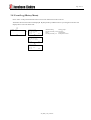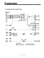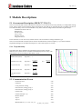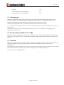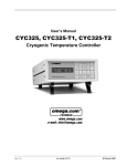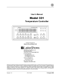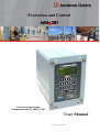
1
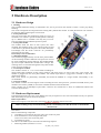
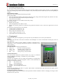
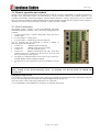
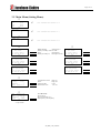
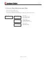
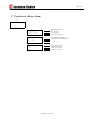
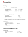
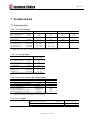
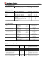
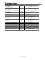
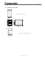
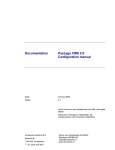
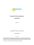
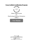
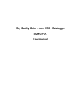
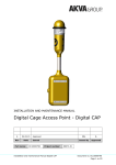
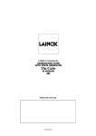
kjøter
Protection and Control
refleX 201
Overcurrent protection
Communication IEC 60870-5-103
User Manual
201_PRD_33A_UK.DOC
Document type:
Page:
User Manual
2 of 19
Document name:
Document no:
Prep.:
RefleX 201_PRD
LIER - NORWAY
App.:
File:
I:\UTVIKLIN\Arc57114\SW57114\App\201_I\201_prd_33a_UK.doc
EOJ
33a
Date:
Var.:
18. nov.. 2010
1 Content
USER MANUAL ........................................................................................................................................ 1
TU
UT
1
TU
CONTENT ................................................................................................................................. 2
UT
TU
UT
2
TU
HARDWARE DESCRIPTION ................................................................................................ 3
UT
TU
2.1
2.2
2.3
2.4
2.5
UT
UT
TU
TU
UT
TU
TU
UT
TU
UT
TU
UT
HARDWARE DESIGN ..................................................................................................................... 3
HARDWARE REPLACEMENT ......................................................................................................... 3
FRONT PANEL ............................................................................................................................... 4
REMOTE OPERATION AND READOUT ............................................................................................. 5
REAR CONNECTIONS .................................................................................................................... 5
TU
UT
UT
TU
UT
TU
UT
UT
3
TU
TU
MENU......................................................................................................................................... 6
UT
TU
3.1
3.2
3.3
3.4
3.5
3.6
3.7
3.8
UT
UT
TU
TU
UT
TU
TU
UT
TU
UT
TU
UT
TU
UT
TU
UT
TU
UT
NAVIGATION ................................................................................................................................ 6
CHANGE A SETTING ...................................................................................................................... 6
SHOW REFLEX SOFTWARE VERSION............................................................................................. 6
CHANGE PASSWORD .................................................................................................................... 6
MAIN MENU (SETTING MENU) ..................................................................................................... 7
IN-SERVICE MENU (ONLINE MEASUREMENT MENU) .................................................................... 8
TRIP RECORDS (HISTORY MENU) ................................................................................................. 9
EVENT LOG (HISTORY MENU) ................................................................................................... 10
TU
UT
UT
TU
UT
TU
UT
TU
UT
TU
UT
TU
UT
UT
4
TU
TU
SCHEMATIC I/O AND LOGIC ............................................................................................ 11
UT
TU
UT
5
TU
MODULE DESCRIPTIONS .................................................................................................. 12
UT
TU
5.1
5.2
5.3
5.4
5.5
UT
UT
TU
TU
UT
TU
TU
UT
TU
UT
TU
UT
OVERCURRENT DESCRIPTION (IEEE C37.2 50, 51) .................................................................... 12
COMMUNICATION/ EVENTS ........................................................................................................ 12
SETTING GROUP ......................................................................................................................... 13
BREAKER FAILURE (IEEE C37.2: 50BF) .................................................................................... 13
PASSWORD ................................................................................................................................. 13
TU
UT
UT
TU
UT
UT
UT
6
TU
TU
TU
SETTINGS ............................................................................................................................... 14
UT
TU
6.1
6.2
6.3
6.4
6.5
UT
UT
TU
TU
UT
TU
TU
UT
TU
UT
TU
UT
OVERCURRENT PROTECTION (IEEE C32.2: 50, 51) ................................................................... 14
COMMUNICATION (IEC 60870-5-103) ....................................................................................... 14
SETTING GROUP ......................................................................................................................... 14
BREAKER FAILURE PROTECTION (IEEE C32.2: 50BF) ............................................................... 14
SYSTEM DATA ............................................................................................................................ 14
TU
UT
UT
TU
UT
UT
UT
TU
7
TU
TU
TECHNICAL DATA .............................................................................................................. 15
UT
TU
7.1
7.2
7.3
UT
UT
TU
TU
UT
TU
TU
UT
ELECTRICAL DATA ..................................................................................................................... 15
ENVIRONMENTAL CONDITIONS................................................................................................... 16
DIMENSIONS AND WEIGHT.......................................................................................................... 18
TU
UT
UT
TU
UT
Ver.:
201_PRD
Page 3 of 19
2 Hardware Description
2.1 Hardware Design
1 Housing
The extruded aluminium housing is maintenance free, and is grooved on the outside to ensure a secure grip during
handling.
The circuit board guides are integrated in the housing and symmetrically located to enable the housing to be turned in
any direction before mounting the circuit boards.
2 Front panel frame
The front panel frame has standard 4U height (177 mm). If
mounted in 19" cubicles a special mounting frame containing
up to 4 RefleX units is available. The relay may of course
also be mounted into an traditional protection panel.
3 Front panel module
This module forms the base of each system unit when
mounted. The multilayer front cover with the 16-key keypad
is attached to a galvanised steel-plate. The mother board, the
LCD-display and the D-sub connector are permanently
attached to the steel plate.
Disassembly is not recommended.
4 Measuring module
This module is plugged directly into the front panel module.
At the measuring module a dedicated microprocessor is used
for signal conditioning and pre-filtering. The module handles
up to seven input channels like currents and/or voltages. The
resulting values are streamed through the front panel module
to the processor module (6).
5 I/O and power module
This module consists of 1 1/2 circuit boards including all
digital input/output insulation circuits (optical isolators and output relays), as well as the unit’s power supply. The
module is plugged into the front panel module. The smaller input board is “piggy-back” mounted on top of the
output/power board.
Both circuit boards are permanently assembled, and should be handled as a single module. Disassembly is not
recommended.
6 Processor module
This module contains the main digital circuits including the main microprocessor, permanent FLASH memory and
random access memory (RAM) as well as the communication functions and interface.
Three complete sets of full-duplex optical fibre connectors are located here to allow for undisturbed internal and
external communication.
2.2 Hardware Replacement
If panel-mounted with rear access, some RefleX parts may be replaced on site. The front module can only be replaced
after dismounting the system unit from the panel.
Removal procedure
Before removing any circuit board all connections to the rear terminals must be removed.
SAFETY NOTICE !
Before working on any current measuring circuit - be absolutely sure that all circuits are shorted and
disconnected !
Disconnect:
Remove the following components:
• Grounding screw located in the lower right corner of the rear panel.
• Four 5mm unbraco screws fixing the rear panel.
One screw in each corner of the rear panel.
• Lift off the rear panel
Now the circuit boards may be removed in the following sequence:
1. Measuring module (terminals A1..A14)
201_PRD_33A_UK.DOC
Page 4 of 19
2. I/O module (terminals B1..B18)
3. Processor board (terminals D1..D6)
Be sure never to remove the I/O module before the measuring module has been safely removed, to avoid damaging
from the grounding strip between the two modules. In any case the processor module may be removed separately if
needed.
Replacement procedure
Install each circuit board using the following procedure :
Insert circuit boards:
• Insert the measuring module to the extreme right in the relay casing (when observing the relay from the rear end).
The component side of the module must point to the right.
• Then insert the I/O module.
• Finally insert the processor module into the relay casing.
Mount the rear panel:
• Replace the rear panel
• Insert and tighten the four unbraco screws
• Replace the external ground wire and fasten the ground wire fastener screw on the lower right side of the rear
panel.
Reconnect all connections to the rear terminals :
• Voltage inputs at terminals A1..A6
• Current inputs at terminals A7..A14
• Binary inputs at terminals B1..B18
• Contact outputs at terminals C1..C18
• Optical fibre links at terminals D1..D6
2.3 Front panel
The RefleX front panel is designed to give the operator easy and efficient access to the system functions.
Display
The display has four lines, each with 16 characters. The backlight is on a few seconds after activating any of the 16
front panel keys.
When the unit is ready to receive changes in settings or functions this is
indicated by a cursor (flashing underline) that appears in the display at the
“open” location.
LED signal lamps
The three LED’s are usually operated like this :
• Green “on”:
the unit is in normal operation
• Green “off”:
watchdog signal or supply error
• Yellow “on”:
unit activated (start) but no trip
• Red
“on”:
unit trip relay is (was) activated
Numerical Keyboard
The three-by-four numerical keyboard enables easy input of numerical
values. A dedicated “blocking” or “disable” key is also included.
Navigation keys
The four grey navigation keys are mainly self-explanatory, but application
examples are found in the menu-navigation section. In this document the
graphic key-symbols are named:
• ESC
Key with text “Esc”
• UP
Arrow pointing up
• DOWN Arrow pointing down
• ENTER Arrow pointing down and left
ID pocket
To the right of the RS232 plug, there is a “pocket”. Here a label is inserted from the right side of the front panel to allow
the user to identify each unit.
Front-panel computer connection
The RS232 plug is used to download the main operational software. Readout of data or changing of settings is done
through the rear optical I/O.
201_PRD_33A_UK.DOC
Page 5 of 19
2.4 Remote operation and readout
Settings can be changed and measured values and trip records are viewed or downloaded via a modem connection or
through a local optical fibre ring-bus. All communication is based on the IEC 60870-5-103 standard. “RefCom” is an
extremely user-friendly software developed by Jacobsen elektro. RefCom is used for quick and easy access to RefleX
relays by mirroring the display and keyboard functions into the computer. Because the user-interface on the computer is
identical to the way the relay front panel is operated, no further training is needed.
2.5 Rear Connections
T
The RefleX system is based on a few interchangeable and highly
standardised hardware modules. Three measuring configurations are
available :
• 3 phase current inputs, 1 sensitive earth fault current input and 3
voltage inputs.
• 4 current inputs, 3 voltage inputs.
• 4 current inputs, 3 voltage inputs (for measurements).
The I/O terminals may be configured to perform a number of
functions, and are labeled like this :
• Column “A” :
Analogue inputs (measuring)
• Column “B” :
8 Binary inputs and power supply
• Column “C” :
8 Contact outputs (relays)
• Column “D” :
Digital communication. D1 and 2 is ST fiber
internal protocol. D3 is RJ45 for LAN, D4 is LC for LAN, and
D5-6 is ST fiber for serial protocol.
• All labels are numbered with the lowest value on top of each row,
and both RefleX cabinet and plug is labeled.
• The function for each connection is shown in schematic in section
4.
X
X
SAFETY NOTICE !
Before working on any current measuring circuit - be absolutely sure that all circuits are shorted and
disconnected !
Changing the rated currents
It is possible to change the rated currents after removing the measuring board from the relay. Instructions on how to
remove the measuring board are found in the “Hardware Replacement” section 2.2.
The rated current wired in measuring board must be set in the menu.
It is recommended to send the RefleX to the factory for changing rated current.
X
201_PRD_33A_UK.DOC
X
Page 6 of 19
3 Menu
3.1 Navigation
RefleX have 4 buttons for navigating in the menu. They are all marked with grey colour.
“Up and Down” buttons are used for moving to next menu picture. After entering Password, the up and down
arrow is used for moving between items in the actual picture
“Enter” button is used to start a session. If enter is used on the In-service menu, then the next in-service picture will be
displayed. When changes should be made in a menu, then also enter is used to start a change session. Password
will be prompted. After entering password, you use the up/down arrow to move to the changeable item in the
menu
Esc
“Esc” button is used to end the session you have entered. If you use “esc” twice, you always end in the normal
menu.
3.2 Change a setting
- Find. Use the “up/down” buttons to find the menu you want to change.
- Select. Use the “enter” button to select the desired menu. Password will be prompted. By means of the
keyboard, enter password (factory setting 1111) followed by “enter”. First menu item will start flashing.
- Change. Use the up/down button to navigate to the menu item you want to change. The flashing item can be
changed. Use keyboard to write new item. If item is alphanumerical, use “enter” to select next legal value.
When a value is changed use the “up/down” buttons to move away from the item before saving setting.
Esc
- Save. Use the “esc” button to leave the setting menu. A question if you want to save new setting will appear.
If settings is OK, then save with “enter” button.
If you want to abort settings use “esc”, and no parameters will be changed.
3.3 Show RefleX software version
Press “1” in normal operation to display the software version in any RefleX module.
Reset the display by pressing ESC.
3.4 Change Password
Password is by factory default set to 1111. It can be selected any combination of four digits from the menu. To disable
the password, enter password 0000.
To change the password, move to the “Date/Time picture”.
Press enter to select. (Year starts blinking)
Press down arrow until the four **** for password is blinking.
Press new password (1234)
Confirm new password (1234)
Save changes by pressing ESC and confirm by pressing enter.
Also please refer to section 5.5.
X
X
201_PRD_33A_UK.DOC
Page 7 of 19
3.5 Main Menu (Setting Menu)
Ú
IN SERVICE
IL1
121A
IL2
IL2
©
For content see section 3.6
©
For content see section 3.7
©
For content see section 3.8
X
X
120A
121A
Ú
TRIP LOG
X
X
Ú
EVENT LOG
X
X
Ú
Low current
#1
I> 400/4.00A
t> 1.50s Def.t
CT 100/1A In 1A
Ú
Module heading
Setting group #
Primary/secondary current set value
Delay
Characteristic
Primary/secondary CT
Rated phase current
Ú
Ú
Med. Current
#1
I>> 600/6.00A
t>> 0.50s Def.t
CT 100/1A In 1A
Med. Current
#2
I>> 600/6.00A
t>> 0.50s Def.t
CT 100/1A In 1A
Ú
Ú
High current
#1
I>>> 800/8.00A
t>>> 0.05s Def.t
CT 100/1A In 1A
High current
#2
I>>> 800/8.00A
t>>> 0.05s Def.t
CT 100/1A In 1A
Ú
Comm. IEC 103
Config.
Ring
Address
1
Meas. Value 1.2
Communication select:
Select:
Address of IED:
Measurement scale
OFF, 103
Ring, Star
0-256
1.2 or 2.4
Ú
YMD
2009-11-25
HMS
13:52:36
Password
****
Freq.
50Hz
Low current
#2
I> 400/4.00A
t> 1.50s Def.t
CT 100/1A In 1A
Year-Month-Day
24 hour clock
Password (default 1111)
Rated power system frequency.
Ú
… to top of menu
201_PRD_33A_UK.DOC
Page 8 of 19
3.6 In-service Menu (Online measurement Menu)
Display shows actual analogue values.
Press “enter” to change between displays.
Chosen display will automatic be the default display. Heading shows the protection functions.
Ú
NORMAL
IN-SERVICE
Ú
©
OC,DEF,Ph-unb
IL1
121A
IL2
120A
IL2
121A
Normal display
Primary value phase current 1
Primary value phase current 2
Primary value phase current 3
©
OC,DEF,Ph-unb
Io
0.1A
Uo
5V
EF Angle
86~
Alternative display 1
Secondary earth fault current
Secondary erath fault voltage
Angle of current with ref. Uo voltage
©
OC,DEF,Ph-unb
I1
120A
I2
0.001*I1
Alternativ display 2
Positive sequence current
Negative sequence current
201_PRD_33A_UK.DOC
Page 9 of 19
3.7 Trip Records (History Menu)
Ú
Trip records
©
Ú
Trip 333
1999-12-12
12:13:14.123
Delay
0.04s
Header contains trip no.
Date of trip 333
Time of trip 333
RefleX delay time of trip
Ø
Tripind
Trip 333
I>* I>>
Iø> Iø>>
I_oc_u
Trip 333
IL1
IL2
IL3
Activated measuring modules
* indicate all trip activated modules
Ø
Header contains trip no.
Current L1 of trip 333
Current L2 of trip 333
Current L3 of trip 333
201_PRD_33A_UK.DOC
Page 10 of 19
3.8 Event Log (History Menu)
Press “enter” in the picture EVENT LOG to move from main menu to the event list.
Automatic the most resent Event is displayed. By help of the up and down arrow you navigate in the list. The
display shows one event at the time.
Ú
EVENT LOG
©
Ú
2010-11-29
12:44:32.024
Start I>>
50/51
ON
Module heading
Setting group #
Primary/secondary current set value
Delay
Characteristic
Primary/secondary CT
Rated phase current
Ú
2010-11-29
12:44:32.215
Trip I>> #151
50/51
ON
Ú
2010-11-29
12:44:32.247
Start I>>
50/51
OFF
201_PRD_33A_UK.DOC
Page 11 of 19
4 Schematic I/O and Logic
201_PRD_33A_UK.DOC
Page 12 of 19
5 Module Descriptions
5.1 Overcurrent Description (IEEE C37.2 50, 51)
The overcurrent module contains instantaneous and time overcurrent functions with possibility of 3 independent setting
levels. It has 3 phase current measuring inputs and output for start and trip. In the menu the user can define overcurrent
level and time delay. The overcurrent module can by menu selection change between the following time delays:
Instantaneous (def.t with t=0)
Definite time
Normal inverse
Very inverse
Extreme inverse
Long time inverse
In the menu the CT ratio can be set, and the In factor can be selected according to hardware type.
The overcurrent module uses DFT (Discret Fourier Transformation) with 24 samples pr. cycle from which the
amplitude and angle are calculated and output as a value of the respective currents.
5.1.1 Trip time delay
100
t(s)
The table below shows formulas for calculating exact trip times with the
different inverse characteristics available in the RefleX protective relays. The
characteristics are all according to IEC 60255-3 norm.
Ni
90
Vi
Ei
80
Definite time (Def.t)
Trip time =
Lti
70
t
60
Normal inverse (Ni)
Very inverse (Vi)
Trip time =
k * 0,14
I00,02 - 1
U
U
I0 =
Imeasure
Isetting
U
50
U
40
k * 13,5
I0 - 1
Trip time =
U
30
U
20
Extreme inverse (Ei)
Long time inverse
(Lti)
Trip time =
k * 80
I02 - 1
Trip time =
k * 120
I00,02 - 1
U
U
U
10
0
1
U
5.2 Communication/ Events
Protection active
<18>
LED reset
<19>
Local parameter setting
<22>
Characteristic (setting group) 1
<23>
Characteristic (setting group) 2
<24>
General Trip
<68>
General start/pick –up
<84>
Breaker failure
<85>
Trip I>
<90>
Trip I>>
<91>
Measurands IL-1,-2,-3, VL-1,-2,-3, f
<148>
201_PRD_33A_UK.DOC
6
11
16
21
26
I(A)
Page 13 of 19
LED reset
<19>
Activate Characteristic (setting group) 1
<23>
Activate Characteristic (setting group) 2
<24>
5.3 Setting group
RefleX has 2 independent setting groups. The Setting Group module reads status from the input terminals or from
communication ports, and changes all displayed settings to group 1 if input is low, and group 2 if input is high.
Selecting setting group from local is possible only when the input local/remote is off (low).
Selecting setting group from remote is possible only when the input local/remote is on (high).
Have in mind when selecting from remote to local control that setting group will change depending of local setting on
RefleX inputs!
The SetGroup module always remembers last selected group, but these is overruled by local setting group when
changing from remote to local.
5.4 Breaker failure (IEEE C37.2: 50BF)
If the fault is still present 200ms after the trip is given, the Breaker Failure function will give Breaker Failure Trip. The
function is used for supervision of the circuit breaker, and breaker failure signal should be routed to the backup circuit
breaker.
5.5 Password
RefleX is provided with a 4 digit password protection. The factory default password is 1111, but is easy for the user to
change. By changing the password to 0000, the password function is disabled. To disable password is not
recommended.
RefleX will always ask for password if user want to enter a menu that can change settings. The password is never asked
for information menus like reading In service picture, reading Trip events, reading of settings etc.
Refer section 3.4 for changing password.
X
X
201_PRD_33A_UK.DOC
Page 14 of 19
6 Settings
6.1 Overcurrent protection (IEEE C32.2: 50, 51)
Measurement
Current settings (1A rated input)
Current settings (5A rated input)
Time characteristics
Time multiplier for inverse time
characteristics
Definit time settings
Reset ratio
Harmonic measurement
Three phases
0,200 - 75,0 A and ∞
1,00 - 375 A and ∞
Ni, Vi, Ei, Lti and Def.t
0,10 – 1,20 and ∞
I>, I>>, I>>>
I>, I>>, I>>>
k>, k>>, k>>>
t>, t>>, t>>>
0,01 – 9.99 s and ∞
>0,97
1st harmonic
6.2 Communication (IEC 60870-5-103)
System configuration
Address
Resolution of measurement (x In)
Tx
Rx
Transmission speed (CD and MD)
Ring/Star
1 to 254*
1.2 or 2.4
Input D5
Output D6
19,2
Kbit/s
*) Setting address 0, will make RefleX to act as slave on address 1, and in addition it will act as time master using
the internal clock.
6.3 Setting Group
Setting Group 1 is active when input is low,
or when selected from communication
(remote)
Setting Group 2 is active when input is high,
or when selected from communication
(remote)
Setting group is selectable from communication
when remote input is high
Input
B13-14
Input
B13-14
Input
B3-4
6.4 Breaker failure protection (IEEE C32.2: 50BF)
Delay before transfer of trip (fixed value)
ms
200
ms
ms
Hz
1111
200 pulse
50 pulse
16⅔, 25, 50, 60
6.5 System data
Factory password
Pulse extension on trip outputs (contacts)
Pulse extension on block inputs
Frequency
201_PRD_33A_UK.DOC
Page 15 of 19
7 Technical data
7.1 Electrical data
7.1.1 AC Current inputs
Type
Phase current
(max 3 inputs)
Io current
(single input)
Rated current - In
(A rms)
1
5
1
5
Max continuos current
(A rms)
10
30
10
30
Max 3 sec current
(A rms)
100
500
100
500
Measuring range 1)
(A rms)
0.1 – 75
0.5 – 375
0.005 - 2
0.075 – 30
A/D saturation
(A peak)
± 106
± 530
± 2.82
± 42.4
Max input impedance
10
2
30
2
(mΩ)
Measuring E/F 2)
(Terminals)
A7 – A8
A7 – A8
Measuring phase L1 2)
(Terminals)
A9 – A10
A9 – A10
Measuring phase L2 2)
(Terminals)
A11 – A12
A11 – A12
Measuring phase L3 2)
(Terminals)
A13 – A14
A13 – A14
1)
Max current is stated for true sine wave with no DC offset. For extreme DC offset conditions divide max values by two.
2)
Change between 1A and 5A rated current at internal connections on measuring module
P
P
P
P
P
P
P
P
P
P
P
P
P
P
7.1.2 AC Voltage inputs
Type
Voltage
(max 3 inputs)
Rated voltage – Un
(V rms)
100 / 110
Max continuos voltage
(V rms)
300
Max 3 sec voltage
(V rms)
500
Measuring range 1)
(V rms)
1 – 170
A/D saturation
(V peak)
± 240
Max burden – ref. Un
(VA)
0.15
Measuring U1
(Terminals)
A1 – A2
Measuring U2
(Terminals)
A3 – A4
Measuring U3
(Terminals)
A5 – A6
1)
Max value is stated for true sine wave with no DC offset.
P
P
P
P
7.1.3 General AC current and voltage inputs
Rated frequencies – fn (three phase)
(Hz)
60 / 50
Rated frequencies – fn (single phase)
(Hz)
25 / 162/3
Filter cut-off frequency
(Hz)
6 * fn
Available harmonics after DFT filter
(* fn)
1/2/3/4/5
A/D conversion (parallel processing) 1)
(bit)
14 + 4
Apparent sampling rate 2)
(samples/cycle)
24
Pre-filter sampling rate 2)
(samples/cycle)
288
Apparent sampling rate ref. 60 Hz
(samples/s)
1440
Pre-filter sampling rate ref. 60 Hz
(samples/s)
17280
1)
Two parallel measuring paths with 1/16 difference in max range
2)
Sampling is automatically synchronised to system frequency
P
P
P
P
P
P
P
P
P
P
P
P
7.1.4 Power supply
Power supply
Supply voltage
Input is located at I/O module
Permissible infeed interrupt time
Power consumption approximately
201_PRD_33A_UK.DOC
(VAC / VDC)
(Terminal)
(ms)
(W)
24 – 240
B17 – B18
100
7 – 11
Page 16 of 19
7.1.5 Digital inputs and
HV isolated digital inputs
(8 separate inputs)
Operating voltage
Inputs are located at I/O module
(Bipolar VDC)
(Terminal)
24 – 240
B1-B2 .. B15-B16
(Terminal)
(Terminal)
(Terminal)
(Terminal)
(Terminal)
(Terminal)
(Terminal)
(Terminal)
(V)
(A)
(A)
(W)
(VA)
C1-C2 / C1-C3
C4-C5 / C4-C6
C7 – C8
C9 – C10
C11 – C12
C13 – C14
C15 – C16
C17 – C18
250 / 440
8
30
20
2000
7.1.6 Output relays
Relay 1 1)
Relay 2 1)
Relay 3 1)
Relay 4 1)
Relay 5 1)
Relay 6 1)
Relay 7 1)
Relay 8 (watchdog)
Contact ratings
Single make / single break contact
Single make / single break contact
Single make-contact (NO contact)
Single make-contact (NO contact)
Single make-contact (NO contact)
Single make-contact (NO contact)
Single make-contact (NO contact)
1)
Single break-contact (NC contact)
Rated voltage / max breaking voltage
Rated current
Make current (max 4s at duty cycle<10%)
Rated breaking capacity (L/R = 20ms)
Rated breaking capacity
All terminals are located at the I/O module
P
P
P
P
P
P
P
P
P
P
P
P
P
P
P
P
1)
P
P
7.1.7 Data interface
Internal unit to unit bus
Serial
1)
Location
(Terminals)
D1 (Tx) – D2 (Rx)
Connector type
2x Optical ST 50/125
Wavelength
(nm)
850
Max signal-rate
(Mbit/sec)
1
Idle state
1 ”Light ON”
Communication protocoll
Location
(Terminal)
D3
LAN Ethernet connection
Connector type
RJ45
Max signal-rate
(Mbit/sec)
10
Comunication protocoll
Location
(Terminal)
D4
LAN Ethernet connection
Connector type
Optical LC 9/125
Wavelength
(nm)
1300
Max signal-rate
(Mbit/sec)
100
Idle state
0 ”Light OFF”
Communication protocoll
Location
(Terminals)
D1 (Tx) – D2 (Rx)
Serial
Connector type
2x Optical ST 50/125
Wavelength
(nm)
850
Max signal-rate
(Mbit/sec)
1
Idle state
1 ”Light ON”
Offline configuration plug
Connection type at relay
9-pin RS232, female
Located at front panel
Lower left corner
Adapter cable (unit to pc)
Standard strigth extension cable
Max cable-length
(m)
10
1)
This channel is used when two ore more units are interconnected to form one single functional unit.
P
P
P
P
7.2 Environmental conditions
Insulation
Dielectric (rated insulation voltage 500V)
Min insulation resistance (test voltage 500V)
Impulse voltage (1.2/50 µs)
Disturbance and immunity (EMC)
1 MHz burst, class III, Common Mode
1 MHz burst, class III, Differential Mode
Fast transients (EFT/burst), Class IV
Common Mode (line-ground)
Fast transients (EFT/burst), Class IV
Differential Mode (line-line)
ESD, Class 3, Discharge voltage, Contact
ESD, Class 3, Discharge voltage, Air
(kV DC)
3.6
(MΩ)
(kV)
100
5
(kV)
(kV)
(kV)
2.5
1
4
(kV)
2
(kV)
(kV)
6
8
201_PRD_33A_UK.DOC
Standard
IEC 60255-5-6
IEC 60255-5 section 4 (draft)
IEC 60255-5-7
IEC 60255-5-8
Standard
IEC 60255-22-1
IEC 60255-22-1
IEC 60255-22-4 / EN 61000-4-4 /
EN 50082-2 clause 2.2, 3.2, 4.2
IEC 60255-22-4 / EN 61000-4-4 /
EN 50082-2 clause 2.2, 3.2, 4.2
IEC 60255-22-2 / EN 61000-4-2
IEC 60255-22-2 / EN 61000-4-2
Page 17 of 19
Conducted RF immunity
(0.15 – 80MHz)
Radiated EM immunity, Class III
(80-1000MHz and 900MHz)
Conducted emissions, Class A ref EN 55022
(0.15 - 0.5 MHz)
(0.5 – 30 MHz)
Radiated emissions, Class A (Test distance 10m)
(30 – 230 MHz)
(230 - 1000 MHz)
Power supply maximum interruption time
Power supply maximum input ripple
(V EMK, CM)
10
(V/m)
10
(µV)
(µV)
79
73
(µV/m)
(µV/m)
(ms)
(%)
40
47
100
100
Climate and temperature
Dry heat, Operation
(°C)
+55
Dry heat, Storage
(°C)
+70
Cold, Operation
(°C)
-10
Cold, Storage
(°C)
-40
Damp heat, Storage 56 days at 40°C
Protection provided by enclosure (complete unit)
Protection provided by enclosure (front panel)
(%)
90-95
IP41
IP53
(g)
(g)
(g)
(g)
(g)
1
2
10
2
1
Mechanical, operation
Vibration response, Class 2 (10-150 Hz)
Vibration endurance, Class 2 (10-150 Hz)
Shock response, Class 2
Seismic, Horizontal, Class 2 (2-35 Hz)
Seismic, Vertical, Class 2 (2-35 Hz)
201_PRD_33A_UK.DOC
EN 61000-4-6
EN 50082-2, Clauses 2.1, 3.1, 4.1
IEC 60255-22-3 / EN 61000-4-3
EN 50081-1(2) / EN 55022
IEC 60255-25 (draft)
EN 50081-1(2) / EN 55022 IEC
and 60255-25 (draft)
IEC 60255-11
IEC 60255-11
Standard
IEC 60255-6
IEC 60068-2-2, test B
IEC 60255-6
IEC 60068-2-2, test B
IEC 60255-6
IEC 60068-2-1, test A
IEC 60255-6
IEC 60068-2-1, test A
IEC 60068-2-3, test C
IEC 60529
IEC 60529
Standard
IEC 60255-21-1 / IEC 60068-2-6
IEC 60255-21-1 / IEC 60068-2-6
IEC 60255-21-2
IEC 60255-21-3
IEC 60255-21-3
Page 18 of 19
7.3 Dimensions and weight
RefleX base-unit. Weight 3.5 kg.
7.3.1 Panel Cut-out
RefleX base-unit panel-mounting cut-out
201_PRD_33A_UK.DOC
Page 19 of 19
Jacobsen Elektro AS
Ringeriksveien 16, 3400 Lier, Norway
Tlf: +47 32 22 93 00 Fax: +47 32 22 93 01
www.jel.no
201_PRD_33A_UK.DOC