1
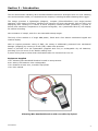
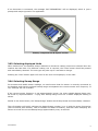
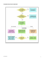
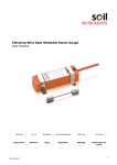
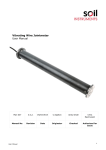
Vibrating Wire Handheld Readout User Manual Man182 2.0.2 07/08/2014 Rob KingMason Phillip Day Phillip Day Manual No. Revision Date Originator Checked Authorised for Issue User Manual 1 Contents Section 1 : Foreword ....................................................................................................... 3 Section 2 : Introduction .................................................................................................. 4 Equipment Supplied ......................................................................................................... 4 Section 3 : 3.01 3.02 3.03 3.04 3.05 3.06 3.07 3.08 Section 4 : Operating Instructions .................................................................................. 5 Fitting the Battery ............................................................................................ 5 Sensor connection ............................................................................................ 5 Selecting displayed Units .................................................................................. 6 Selecting Sweep Range ..................................................................................... 6 LCD Back Light ................................................................................................ 7 Auto-Timeout .................................................................................................. 7 Maintenance .................................................................................................... 7 Data Interpretation........................................................................................... 7 Troubleshooting Guide .................................................................................. 8 TROUBLE SHOOTING FLOWCHART .................................................................................... 9 Appendix A. User Manual Vibrating Wire Data ................................................................................... 10 2 Section 1 : Foreword Soil Instruments Vibrating Wire Handheld Readout, as with all our equipment, has been designed to operate consistently in a construction site environment and is therefore relatively robust. However, it is essential that the equipment covered by this manual, is handled, operated and maintained by competent and suitably qualified personnel. They must READ AND UNDERSTAND the procedures outlined in this manual before attempting operation of the equipment on site. Soil Instruments will not accept for repair under guarantee, instruments that have been neglected or mishandled in any way User Manual 3 Section 2 : Introduction The Soil Instruments Vibrating Wire Handheld Readout has been developed as a low cost vibrating wire and thermistor reader, to complement the company’s existing Portable Vibrating Wire Logger. The design provides a lightweight (680gms), compact (250x125x25mm) and single-handed operation, field-means of exciting vibrating wire sensors and their thermistors (3KΩ at 25ºC) and displaying their readings in a choice of three frequency-related formats (Frequency, F²/1000 or Period) and transducer temperature in degrees Centigrade, via a (switchable back-lit) LCD display for manual recording. Wire excitation is ‘swept’, with four user selectable sweep ranges. The body of the readout is of tough ABS plastic, faced with a four-button membrane keypad and readout display. With an ingress protection rating of IP65, the casing is additionally protected from mechanical damage (dropping) by housing in a soft (TPE) rubber case protector. Power is provided via 4 AA replaceable (supplied with unit) or rechargeable dry cell batteries, providing up to 30 hours of non-backlit reading time. A power saving feature shuts down the Readout after 30 minutes from turn on. Equipment Supplied 1 No. Vibrating Wire Handheld Readout housed in case protector. 4 No. AA dry-cell batteries. Non rechargeable. 1 No. Readout-to-bare wire, crocodile-clip flylead. 1 No. User manual Vibrating Wire Handheld Readout with crocodile clip flylead User Manual 4 Section 3 : Operating Instructions Remove the Handheld Readout, packet of batteries and flylead(s) from all shipping packaging. 3.01 Fitting the Battery Before operation, the batteries will need to be fitted, which requires turning the Readout over so that it is facedown. At the back of the Readout ‘head’, a black access cover can be identified with a clip closure at its upper end. The cover is removed by inserting a fingernail at the top of the clip and depressing it. The cover will unclip loose, then it may be removed and put to one side. The battery compartment is now revealed. The four AA batteries may now be inserted between the terminals, ensuring correct orientation according to the clear markings beneath each battery location. Once located, the battery compartment cover may now be replaced. Make sure the light grey seal encircling the battery compartment has not been displaced from its groove. If so, push it back into place so that it is sitting evenly within the groove. Locate the lower end lug on the compartment cover into the compartment lower end slot and then push down the cover at its upper end until the clip ‘clicks’ clearly into place. 3.02 Sensor connection Turn the readout back over and remove the dust cap from the connector socket located at the top end of the readout. Store this cap safely. Take the required flylead and carefully aligning its connector with the socket, push the two together until they ‘click’. The other end of the lead may now be connected to their sensor or switchbox. If using the crocodile clips ensure that red is connected to red and the black crocodile clip to the black (or sometimes blue) sensor wire. The polarity of the thermistor wires (if fitted to the sensor), usually green and white, is not important, but for convention, white connect to white and green connect to green. Make sure that the wires and crocodile clips are lying so that they do not touch each other. If the vibrating wire circuit should ‘short’, the VW Readout will shut down to protect the circuitry. If connecting to a switchbox via the switchbox flylead, insert the connector into the switchbox socket after careful alignment and select the required sensor via the rotary channel switches. The Handheld Readout is now switched on by depressing and holding the ‘On/Off’ button for about 1 second, until ‘Soil Instruments’ appears on the LCD screen release the on/off button and ‘Handheld VW Readout’ scrolls across the lower row. There will then be a pause of 5 seconds or so, whilst the Readout self tests and checks after which the upper row will display the vibrating wire reading in frequency and the lower row the sensor temperature in °C. User Manual 5 If no thermistor is connected, the message ‘NO THERMISTOR?’ will be displayed, which is just a prompt and maybe ignored if not applicable. Battery compartment & flylead socket 3.03 Selecting displayed Units When switched on, the Readout always defaults to whichever reading units were selected when the readout was last used. If a different reading unit is required, the ‘Units’ button should be pressed and immediately released. The unit type may take up to 2 seconds to change. Pressing the ‘Units’ button again will scroll to the next unit displayed, in the order 3.04 Selecting Sweep Range For accurate and stable sensor readings, we need ensure that the sensor is correctly connected to the Readout and that the selected sweep range encompasses the current sensor wire frequency. If not, readings will not be stable. If the current sensor frequency is not approximately known, the most suitable Sweep Range may be found by experimentation – trying each Sweep Range until the a stable displayed reading is shown. Similar to the Units button, the ‘Sweep Range’ button should be pressed and immediately released. The LCD display will briefly indicate the Sweep Range number (1 to 4) and the range frequencies (450 to 1250Hz, 800-2000Hz, 1400 to 3500Hz and 2400 to 6000Hz), and then start ‘sweeping’ the sensor wire with the current Sweep Range approximately every 4 seconds. User Manual 6 3.05 LCD Back Light For low light sensor reading, the LCD display maybe backlit to assist display viewing. The backlight is switched on and off by pressing and releasing the ‘Back Light’ button. It should be noted that use of the backlight, will significantly decrease battery life. 3.06 Auto-Timeout A power saving ‘Timeout’ feature is built into the software, which will shut down the Handheld Readout after 30 minutes of operation. 3.07 Maintenance Little maintenance is required apart from wiping over the Readout casing with a damp cloth to remove dust and dirt and the occasional replacement or recharging of the dry-cell batteries. Spare batteries should be considered so that continuity of service maybe assured. 3.08 Data Interpretation Conversion of Period and Linear Units to Engineering Units is carried out using the formulae detailed below: - Period Units P=K 7 7 10 10 2 T 2 T1 o Where: P = Engineering Units K = Gauge Calibration Constant for Period units To = Base reading in Period units T1 = Current reading in Period units Frequency² Units P = K [0.0001( Fo - F1)] Where: P = Engineering Units K = Gauge Calibration Constant (for Period Units) Fo = Base reading in f2/1000 units F1 = Current reading in f2 /1000 units Please see Appendix 1 for more information on Vibrating Wire data. User Manual 7 Section 4 : Troubleshooting Guide If a failure of any vibrating wire transducer or its electrical cable is suspected, the following steps can be followed. The transducers themselves are sealed and cannot be opened for inspection. The “Troubleshooting Flowchart” should also be followed if any instrument failures are suspected. The steps below and the Troubleshooting Flowchart are applicable generally to any vibrating wire instrument. Step 1 Before any of the following steps are followed, the readout unit should be used to verify the stability of the reading. The period reading from the transducer should not vary by more than ± 3 units. An unstable (wildly fluctuating) reading from a transducer is an indication of possible problems with instruments or their related electrical cables. IMPORTANT: If a handheld readout is giving faulty readings from all transducers, a faulty readout unit must be suspected. Another readout unit should be used to check the readings from the transducers and Soil Instruments Ltd should be consulted about the faulty readout unit. Before proceeding to Steps 2 and 3, if possible the continuity should be checked between conductors and earthing screen of the electrical cable. If continuity exists, a damaged cable is confirmed. Step 2 The resistance across the two conductors of the electrical cable should be checked. This can be done using a multimeter device across the two exposed conductors if the cable has not been connected to a terminal cabinet, or can be done just as easily across the two conductors if the instrument has been connected to such a terminal (or dataloggers). The resistance across the two conductors should be approximately of the order of 80 to 180. The majority of these resistances arises from the transducer and the remainder from the electrical cable connected to the transducer. Step 3 If the resistance across the two conductors is much higher or lower than the values quoted in “Step 2” (or is infinite), a damaged cable must be suspected. Step 4 If the resistance is within the values quoted in “Step 1” (i.e. 80 to 180), AND no continuity exists between conductor and earth screen and on checking the reading from the transducer, it proves to be still unstable or wildly fluctuating, it must be assumed that the integrity of the circuit is good. A faulty transducer must be suspected and Soil Instruments Ltd should be consulted. NOTE: User Manual If the location on site of cable damage is found, the cable can be spliced in accordance with recommended procedure with suitably qualified personnel. 8 TROUBLE SHOOTING FLOWCHART User Manual 9 Appendix A. Vibrating Wire Data Vibrating Wire Units Frequency Units ( f ) The tension of a wire can be measured by registering the frequency (note) at which it naturally vibrates. If the wire is “swept” electronically, the frequency at which it vibrates can be measured. The most common units used to express frequency are Hertz (Hz) or Kilo-Hertz(KHz). The disadvantage of these units is that there is no “linear” conversion from Hertz to “change in wire tension”. Frequency²/1000 Units ( L ) In order to overcome the problem of a linear conversion described above, the frequency value can be squared, thereby rendering it linear, but quite large. To reduce its size it is often divided by 1000 (or multiplied by 10 -3). The expression f²/1000 (or f² x 10-3) is the most commonly adopted as a “linear” output. Period Units ( P ) Electronic devices and digital technology often utilise the “counter” function available in some common circuits. Period Units represent the time taken for the wire to vibrate over one full oscillation, expressed in seconds. Due to the very small size of the number generated most equipment manufacturers display the unit multiplied by 10000000 (or 107). The relationship between Period Units and frequency units is expressed as; P = 1/ Frequency Period units are, therefore, convenient to measure but do not have a linear relationship to “change in wire tension”. Calibration Constants Each instrument is supplied with a Calibration Constant value, to convert the raw data into Engineering Units. The value of the calibration constant will vary depending upon the engineering units into which the data is to be converted and the readout units. For example, the data from piezometers may convert into mH20, Bar, Psi, etc, and, therefore, the Calibration Constant for each will be different. Some instruments have “Generic” Calibration Constants and others are individually calibrated to generate the Constant. The constant is generated by using the following calculation: Constant (K) = Range (107) - (107) (R1) (R2) R1 = (Reading at zero range)² R2 = (Reading at full range)² Bell Lane, Uckfield, East Sussex t: +44 (0) 1825 765044 e: [email protected] TN22 1QL United Kingdom f: +44 (0) 1825 744398 w: www.itmsoil.com Soil Instruments Ltd. Registered in England. Number: 07960087. Registered Office: 5th Floor, 24 Old Bond Street, London, W1S 4AW User Manual 10