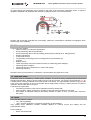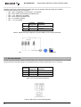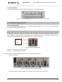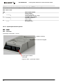
1
MT830/MT831 Three-phase electronic multi-function meter for industry Technical Description EAD 020 611 368 Version 1.7, 27.05.2013 MT830-MT831_TD_eng_V1.7.docx Table of contents: 1. List of standards ....................................................................................................3 2. Safety ......................................................................................................................4 2.1. Responsibilities .................................................................................................4 2.2. Safety instructions .............................................................................................4 3. Introduction ..........................................................................................................11 4. Meter characteristics ...........................................................................................12 5. Constituent parts .................................................................................................14 5.1. Measuring system ...........................................................................................14 5.2. Microcomputer.................................................................................................15 5.3. Real time clock ................................................................................................15 5.4. LEDs................................................................................................................15 6. Multi-tariff registration.........................................................................................16 7. Maximum demand indicator ...............................................................................16 8. Load Profile ..........................................................................................................16 9. Registration of energy / power ...........................................................................16 10. Display ................................................................................................................17 10.1. Keys...............................................................................................................18 11. Communication interfaces................................................................................18 11.1. IR communication interface...........................................................................18 11.1.1. Meter reading in absence of measuring voltages (option) .....................18 11.2. RS-485 interface ...........................................................................................19 11.3. RS-232 interface ...........................................................................................20 11.4. CS-communication interface .........................................................................21 12. Input /output module (MT831 meter only) .......................................................21 13. Communication module (MT831 meter only) ..................................................23 14. Fraud protection ................................................................................................24 14.1. Detection of meter cover and terminal cover opening ..................................24 15. Handling with the meter ....................................................................................25 16. Connection procedure.......................................................................................25 16.1. 3phase 3wire connection...............................................................................26 17. Housing...............................................................................................................26 17.1. Terminal block ...............................................................................................28 17.2. Current terminals...........................................................................................28 17.3. Auxiliary voltage terminals.............................................................................29 17.4. Sliding voltage bridge (at direct connected meter)........................................29 17.5. Cop5 terminal ................................................................................................30 17.6. Dimensions....................................................................................................30 18. Sealing ................................................................................................................31 19. Maintenance .......................................................................................................31 20. Lifetime ...............................................................................................................31 21. Technical data ....................................................................................................32 22. Type designation ...............................................................................................35 22.1. Meter type designation ..................................................................................35 22.2. Input-output module type designation (for MT831 meter only) .....................36 22.2.1. Input/output module options: ..................................................................36 22.3. Communication module type designation (for MT831 meters only) .............37 22.3.1. Communication module options: ............................................................37 23. Configuring a PC modem..................................................................................41 24. Appendix A: OBIS codes and data names ......................................................47 25. Appendix B: Log book events ..........................................................................56 26. Appendix C: Connection diagrams ..................................................................58 MT830-MT831_TD_eng_V1.7.docx Disclaimer Iskraemeco, d.d. reserves the right to change these document at any time without prior notice. No part of this document may be reproduced, stored or transmitted in any form whatsoever without prior written approval of Iskraemeco, d.d.. This document is for information only. The content of this document should not be construed as a commitment, representation, warranty, or guarantee for any method, product, or device by Iskraemeco, d.d. and are registered trademarks of Iskraemeco, d.d.. The contents of this document are the copyrighted (registered and unregistered) or trademarked property of Iskraemeco, d.d. and are protected under applicable trademark and copyright law. Unauthorized use may be subject to criminal and material liability. 1. List of standards • • • • • • • • • • • • • • • • • • • • • • • • • • • IEC 60068-2-1 Environmental testing – Part 2-1: Tests – Test A: Cold, IEC 60068-2-2 Environmental testing – Part 2-2: Tests – Test B: Dry heat, IEC 60068-2-30 Environmental testing – test Db: Damp heat cyclic test, Variant 1, IEC 61000-4-2 Electromagnetic compatibility (EMC) - Part 4-2: Testing and measurement, techniques - Electrostatic discharge immunity test, IEC 61000-4-3 Electromagnetic compatibility (EMC) - Part 4-3: Testing and measurement, techniques - Radiated, radio-frequency, electromagnetic field immunity test & IEC 61000-4-20 Testing and measurement techniques - Emission and immunity testing in transverse electromagnetic (TEM) waveguides, IEC 61000-4-4 Electromagnetic compatibility (EMC) - Part 4-4: Testing and measurement, techniques - Electrical fast transient/burst immunity test, IEC 61000-4-5 Electromagnetic compatibility (EMC) - Part 4-5: Testing and measurement, techniques - Surge immunity test, IEC 61000-4-6 Electromagnetic compatibility (EMC) - Part 4-6: Testing and measurement, techniques - Immunity to conducted disturbances, induced by radio-frequency fields, IEC 61000-4-12:1995 Electromagnetic compatibility (EMC) - Part 4-12: Testing and measurement techniques - Oscillatory waves immunity test, CISPR 22 (1997) + A1 (2000), IEC 61000-4-20 (2003) Radio interference suppression, IEC 62052-11 Electricity metering equipment (AC) – General requirements, tests and test conditions – Metering equipment, IEC 62053-21 Electricity metering equipment (a.c.) - static meters for active energy (classes 1 and 2), IEC 62053-22 Electricity metering equipment (a.c.) - static meters for active energy (classes 0.2 and 0.5), IEC 62053-23 Electricity metering equipment (a.c.) - static meters for reactive energy (classes 2 and 3), IEC 62056-21 Electricity metering - Data exchange for meter reading, tariff and load control – Direct local data exchange, IEC 60695-2-11 Fire hazard testing part 2-11: Glowing/hot-wire based test methods - Glow-wire flammability test method for end-products, EN / IEC 60068-2-75 Environmental testing - Part 2-75: Tests - Test Eh: Hammer tests, EN 50470-1 Electricity metering equipment (a.c.) - Part 1: General requirements, tests and test conditions - Metering equipment (class indexes A, B and C), EN 50470-3 Electricity metering equipment Static meters for active energy, classes A, B and C, draft IEC 62053-24, Electricity metering equipment (AC.) - Particular requirements – Static meters for reactive energy (classes 0,5 S, 1 S and 1), EN / IEC 60068-2-27 Basic envirionmental testing procedures - Tests - Tests Ea and guidance: Shock, EN / IEC 60068-2-6 Basic envirionmental testing procedures - Tests - Tests Fc: Vibration (sinusoidal). MT830-MT831_TD_eng_V1.7.docx MT830/MT831 Three-phase electronic multi-function meter . 2. Safety 2.1. Responsibilities The owner of the meter is responsible to assure that all authorized persons who work with the meter read and understand the parts of the User Manual and Installation and Maintenance Manual that explains the safe handling with the meter. The personnel must be sufficiently qualified for the work that will be performed. The installation personnel must possess the required electrical knowledge and skills, and must be authorised by the utility to perform the installation procedure. The personnel must strictly follow the safety regulations and operating instructions, written in the individual chapters in this User Manual and in the Installation and Maintenance Manual. The owner of the meter respond specially for the protection of the persons, for prevention of material damage and for training of personnel. 2.2. Safety instructions CAUTION: At the beginning of handling with the meter, the meter should be carefully taken out of the box where it was packed. This should prevent the meter from falling as well as any other external or internal damage to the device and personal injuries. Should such an incident occur despite all precautions, the meter may not be installed at the metering point as such damage may result in different hazards. In such case the meter needs to be sent back to the manufacturer for examination and testing. CAUTION: The edges of the seal wires are sharp. CAUTION: The temperature of the terminal block of the connected and operating meter may rise, therefore the temperature of the terminal cover may rise as well. DANGER: In case of any damage inside the meter (fire, explosion...) do not open the meter. CAUTION: The meter may be used only for the purpose of measurement for which it was produced. Any misuse of the meter will lead to potential hazards. WARNING: Safety measures should be observed at all times. Do not break the seals or open the meter at any time! The content of this Technical description provides all information necessary for safe selection of MT174 meter. 4 MT830/MT831 Three-phase electronic multi-function meter See the complete Technical description for detailed technical features of MT174 and its intended use. It must be consulted in all cases where symbol is marked in order to find out the nature of the potential hazards and any actions which have to be taken to avoid them. The meter installation procedure is described in this Technical description. For safety reasons the following instructions should be followed. Only the properly connected meter can measure correctly. Every connecting error results in a financial loss for the power company. DANGER: The MT174 electricity meter is the device, connected to the power supply. Any unauthorized manipulation of the device is dangerous for life and prohibited according to the applicable legislation. Any attempt to damage the seals as well as any unauthorized opening of the terminal or meter cover is strictly forbidden. DANGER: Breaking the seals and removing the terminal cover or meter cover will lead to potential hazards because there are live electrical parts inside. Installation companies shall implement a training policy that ensures that new installers are adequately trained, understand risk and safety issues and possess the relevant skills before they commence operational duties. The installer will need to recognise and understand different metering installations, the meter type and various equipments associated with those installations applicable to the successful installation of the electricity meter. The installer must consult and comply with local regulations and read the installation instructions written in this Technical description. The installer will be considered as a public face by both the power company and its customers. The installer shall adopt the highest standards of behaviour and be respectful to clients and members of the public. 5 MT830/MT831 Three-phase electronic multi-function meter Before the installation procedure check if the metering point is correctly prepared for meter installation. The metering point must always be left clean and in order. The work location shall be defined and clearly marked. Adequate working space as well as means of access and lighting shall be provided at all parts of an electrical installation on, with, or near which any work activity is to be carried out. Where necessary, safe access to the work location shall be clearly marked. WARNING: The metering point must not be exposed to running water or fire. WARNING: Meter installation may not be performed by unauthorised and untrained personnel. Such persons are not allowed to cut the seals and open the terminal or meter cover as contact with the live parts of the meter is dangerous for life. DANGER: Opening the terminal or meter cover is dangerous for life because there are live parts inside. CAUTION: The installer is expected to fully understand the risks and safety issues involved in electrical installations. The installer shall be aware at all times of the potential hazard of electrical shock and shall exercise due to caution in completing the task! Installation personnel must possess the required electrical knowledge and skills and must be authorised by the utility to perform the installation procedure. The installer is obligated to perform the installation procedure in accordance with the national legislation and internal norms of the utility. National legislation can set out the minimum age and the criteria for competence of installers. Where there are no national requirements for competence, the following criteria shall be used in assessing the competence of installers: knowledge of electricity, experience of electrical work, understanding of the installation to be worked on and practical experience of that work, understanding the hazards which can arise during the work and the precautions to be observed, ability to recognize at all times whether it is safe to continue working. According to the basic principles, either the nominated person in control of the electrical installation or the nominated person in control of the work activity shall ensure that specific and detailed instructions are 6 MT830/MT831 Three-phase electronic multi-function meter given to the personnel carrying out the work before starting and on completion of the work. Before starting work, the nominated person in control of the work activity shall give notification to the nominated person in control of the electrical installation, of the nature, place and consequences to the electrical installation of the intended work. Tools, equipment and devices shall comply with the requirements of relevant National or International Standards where these exist. Tools, equipment and devices shall be used in accordance with the instructions and/or guidance provided by the manufacturer or supplier. Any tools, equipment and devices provided for the purpose of safe operation of, or work on, with, or near electrical installations shall be suitable for that use, be maintained and be properly used. Personnel shall wear clothing suitable for the locations and conditions where they are working. This could include the use of close-fitting clothing or additional PPE (personal protective equipment). CAUTION: The installer must be correctly equipped with personal protection equipment (PPE) and use the appropriate tools at all times during the installation. CAUTION: Working procedures are divided into three different procedures: dead working, live working, and working in the vicinity of live parts. All these procedures are based on the use of protective measures against electric shock and/or the effects of short-circuits and arcing. The installer must be informed if the national legislation permits the work on the installation under voltage – live work, and must follow the rules of legislation. Depending on the kind of work, the personnel working in such conditions shall be instructed or skilled. Live working requires the use of specific procedures. Instructions shall be given how to maintain tools, equipment and devices in good working order and how to verify them before working. This subclause deals with the essential requirements (“the five safety or golden rules”) for ensuring that the electrical installation at the work location is dead and secure for the duration of the work. This shall require clear identification of the work location. After the respective electrical installations have been identified, the following five essential requirements shall be undertaken in the specified order unless there are essential reasons for doing otherwise: disconnect completely (1.), secure against re-connection (2.), verify that the installation is dead (3.), carry out earthing and short-circuiting (4.) and provide protection against adjacent live parts (5.). CAUTION: Do not attempt to install the meter before you have isolated the installation site from the network! 7 MT830/MT831 Three-phase electronic multi-function meter DANGER: The relevant preliminary fuses must be removed before making any modifications to the installation, and kept safe until completing the work to prevent the unnoticed reinsertion. DANGER: The current transformer secondary circuits must not be opened when current is flowing in the primary circuit. This would produce a dangerous voltage of several thousands volts at the terminals and the insulation of the transformer would be destroyed. DANGER: Connecting the meter into the network under voltage is dangerous for life so the conductors at the metering point must not be connected to any voltage source during the connection procedure. The meter connection procedure may only be performed by well-trained and adequately authorized personnel. CAUTION: Only one wire or ferrule may be connected in one terminal. Otherwise, the terminal could be damaged or the contact could not be made properly. CAUTION: Do not use cables other than those prescribed for the installation site. DANGER: The insulation of the connecting cable must extend over the whole visible part of the cable. There must be no further bare part of the cable visible above the terminal edge. Touching live parts is dangerous for life. The stripped part of the connecting wire should be shortened if necessary. CAUTION: At the end of installation at the metering point no cable should stay unconnected or hanging freely from the metering point. The meter has to be mounted on a smooth vertical surface and fixed at 2 or 3 points with screws using the proper torque. (the meter has two attachment holes and, optionally, a top hanger). The meter is intended to be mounted at an indoor metering point, in a meter cabinet, secured against the undesired access of unauthorized persons. Only scroll push button may be accessible from the outside. Do not expose meter surface to very high temperatures even though the surface is made of inflammable plastics to prevent fire. CAUTION: Electrical connection: mounting cables must be properly dimensioned and of proper shape. They must be mounted using the proper torque. The meter should be connected according to the meter connection diagram that is attached to the inner side of the meter terminal cover. Screws on the current terminal 8 MT830/MT831 Three-phase electronic multi-function meter must be tightened to proper torque. The protective earth connector shall be connected first and it shall not be removed until the meter is fully isolated from the network. CAUTION: If it is possible to install the meter without isolation from the network, i.e. on live network, then appropriate instructions and safety warnings shall be provided. CAUTION:Specific aspects and safety hazards related to external voltage and current transformers, auxiliary supplies and local generation shall be covered. DANGER: The current transformer circuits must be closed before commissioning and functional check of the meter. DANGER: The preliminary fuses must be re-inserted before commissioning and functional check of the meter. CAUTION Seals on the meter have to be checked at the end of the installation procedure so that the final customer can not come into contact with live parts of the meter. DANGER: If the terminal cover is not screwed tight, there is a danger of contact with the connection terminals. Contact with live parts of the meter is dangerous for life. CAUTION: For safety reasons, replace the terminal cover immediately after the installation procedure and fix it with fixing screws. DANGER: When switching on the power beware of the risk of electric shock at all times! The functional check requires voltage to be applied and load applied to all phases. If export is possible, determine first the energy direction present. If no mains voltage is present, commissioning and functional check must be performed at a later date. No maintenance is required during the meter’s life-time. The implemented metering technique, built-in components and manufacturing process ensure high long-term stability of meters, so that there is no need for their recalibration during their life-time. 9 MT830/MT831 Three-phase electronic multi-function meter If a battery is built into the meter, its capacity is sufficient to backup all meter functions like RTC and tampering functions for its entire life-time. In case the service of the meter is needed, the requirements from the meter installation procedure must be observed and followed. Cleaning of the meter is allowed only with a soft dry cloth. Cleaning is allowed only in upper part of the meter – in region of the LCD. Cleaning is forbidden in the region of terminal cover. Cleaning can be performed only by the personnel, responsible for meter maintenance. CAUTION: Do not try to erase the markings, laser printed on the name plate. DANGER: Never clean soiled meters under running water or with high pressure devices. Penetrating water can cause short circuits. A damp cleaning cloth is sufficient to remove normal dirt such as dust. If the meter is more heavily soiled, it should be dismounted and sent to the responsible service or repair centre. While dismounting the meter observe and follow the same safety regulations and instructions as for installation of the meter. CAUTION: Visible signs of fraud attempt (mechanical damages, presence of a liquid, etc.) must be regularly checked. The quality of seals and the state of the terminals and connectiog cables must be regularly checked. If there exist a suspicioun of incorrect operation of the meter, the local utility must be informed immediatelly. After the end of the meter’s lifetime, the meter should be treated according to the Waste Electric and Electronic Directive (WEEE). 10 MT830/MT831 Three-phase electronic multi-function meter 3. Introduction MT830/MT831 three-phase electronic multi-function meter is intended for measuring active and apparent energy in two flow directions, reactive energy in four quadrants as well as imported and exported, maximal power of the above stated energies, registration of load curves and quality parameters of supplied electric energy in three-phase three- and four-wire networks. The meters can be connected directly, semi-indirectly or indirectly. They comply with the IEC 62052–11, IEC 62053-21, EN 50470-3, IEC 62053-22 and IEC 62053-23 standards, VDEW demands, and they are manufactured in compliance with the ISO 9001 standard. MT83y meters comply with the IEC 50579 standard and the current valid FNN instructions "Leitfaden zur Bewertung der Zuverlässigkeit und Messbeständigkeit von Elektrizitätszählern und Zusatzeinrichtungen" from november 2011. MT83y meters can be installed in photovoltaic and cogeneration systems. The meter consists of a polycarbonate housing, electronics for measuring and processing measuring data, input/output as well as communication electronics. Two different meter versions are available: • MT830 - a “closed” meter version with additional six terminals, which could be used for: o communication interface, o functional or impulse inputs, o functional outputs, o external power supply. Figure 1: MT830 – a “closed” meter version • MT831 – a modular meter version with communication (MK) and input/output (MIO) module which could be subsequently built into the meter and six additional terminals. 11 MT830/MT831 Three-phase electronic multi-function meter Figure 2: MT831 – a modular meter version 4. Meter characteristics • Measuring active energy/power. • Measuring reactive energy/power in four quadrants and/or a sum of energies by individual quadrants (e.g. Q1+Q2 and Q3+Q4). • Measuring apparent energy/power. • Calculating cumulative power. • Measuring and displaying parameters of energy quality: rms voltage values by phases, current by phases, th harmonic components in voltage and current (up to the 8 harmonic), power factor per phase and total, phase angle between phase voltage and current, voltage failures. • Multi-tariff registration. • Load profiles (P.01, P.02). • Log-books (P.98, P.99). • Different display modes on LCD. • Meter reading in case of power down (“no power reading” option with SONDA 6 (option)). • VDEW designed LCD • Communications. • IR interface for a local readout and meter programming (IEC 62056-21). • Auxiliary terminals: the main meter board (MT830 & MT831) could be equipped with up to six auxiliary terminals, which could be: Communication on board port (MT830 only) MT830 meter could be equipped with CS interface or RS-485 interface or RS-232 interface. • • • 12 presence of phase voltages, energy flow direction, units and 11 statuses. Communication with the meter is performed in compliance with the IEC 62056-21 standard, mode C. The meter operation is not affected during communication. Type of communication: Serial asynchronous half-duplex ISO 1177 1 start bit MT830/MT831 Three-phase electronic multi-function meter 7 data bits 1 bit parity – even 1 stop bit data transfer rate: 300, 600, 1200, 2400, 4800, 9600, 19200 Baud Each communication port supports “fix” baud rate (for use of transparent telephone modems) or communication protocol according to IEC 62056-21 standard (communication sequence is started with 300 baud). Communication parameters in the meter are programmable. The meter enables separate read out (different data) via IR and other communication interface at the same time. The MT831 meter could be equipped with different communication modules (MK). Two inputs (3 terminals) are used: functional or impulse inputs. • • • Control voltage is from 100 V .240 V AC/DC. At MT831 meter additional inputs & outputs could be implemented in input/output module (I/O module). Electrical characteristics: OFF state <= 30 V, ON state >= 45 V, internal resistance 190kOhm, switch on delay typical 10ms at 240V. Four outputs in two functional groups (6 terminals). External power supply (2 terminals). • • Terminal Terminal Additional designation explanation 30 50 – 240 V External power supply AC/DC 31 50 – 240 V External power supply AC/DC Table 1: Terminals for external power supply • Modular construction at the MT831 meter: MT831 could be upgraded with input/output (MIO) and communication (MK) module. • Fraud detection: detection of a meter cover and a terminal cover opening. • Quality: High accuracy as well as time stability of measurement. High reliability of operation and long life span (20 years). • High immunity to EMC disturbances. • Simple and fast assembly. • A compact plastic housing is made of high quality self-extinguishable materials and is resistant to water and dust penetration (IP53). Environment friendly: a meter is made of the materials that can be recycled or are not dangerous for the environment. • 13 MT830/MT831 Three-phase electronic multi-function meter 5. Constituent parts The meter consists of the following units: • measuring systems, • microcontroller with external memory, • real time clock, • LCD, • optical interface, • keys, • LEDs , • power supply : o internal three phase switcher, o external power supply, o power supply via optical probe (“no power” reading option with SONDA 6). BUTTONS LCD OUTPUTS TAMPER INPUTS AUX Power supply from optical probe CPU Switching power supply multirange MEAS SYS. 2 S RTC BACKU External switching power MEAS SYS. 1 R MEMORY: -FLASH -SRAM -FRAM O MEAS SYS. 3 T Adapter for I/O and COMM Modul I/O Modul COMM Modul CS --------------RS-232 --------------RS-485 Figure 3: A meter block diagram 5.1. Measuring system The measuring systems are based on Rogowski coils that measure changes on the induced voltage. Current flows through a current coil. Voltage is induced inside the air coils due to alternate magnetic field. There are two Rogowski coils on each phase. The measuring system is made of: 1. current coil frame 2. current coil 3. two Rogowski coils 4. PCB Figure 4: Measuring system A measuring system measures induced voltage on measuring coils which is proportional to the current on input. The first coil measures “load” energy and the second one is a compensation coil which measures outside disturbances. Compensation value is subtracted from a measuring element. 14 MT830/MT831 Three-phase electronic multi-function meter An output signal from Rogowski coils is related to the input of the measuring integrated current. A signal is integrated, amplified and multiplied with measuring voltage and sent to the microprocessor. Figure 5: Measuring principle Sensors and circuits are protected from overvoltage. Influences of disturbance quantities are negligible, which assures high meter reliability. 5.2. Microcomputer A microcomputer enables: • meter functions by customer’s specification, • storing measuring data and parameters, • storing measuring data for previous billing periods (factory settings is 15 billing periods), • demand calculations, • Load Profile function, • compensating measuring protocol of voltage and current transformers, • Logbook, • Display control, • certain supervision and control meter functions for measuring phase voltages, • measuring phase voltages, • measuring harmonic components in current and voltage, • measuring frequency. Operation of the microcomputer is controlled by a special Watch-dog supervisor circuit. 5.3. Real time clock A real time clock is controlled by a 32kHz quartz oscillator. The clock accuracy complies with the IEC 61038 standard requirements. Back up power supply source is built in the meter. It is usually a supercapacitor or?? an Li battery which is directly soldered to the main printed circuit board. The supercapacitor assures energy for 250 hours of the clock operation in case of a complete power supply failure, while an Li battery assures 10 years of operation, with time life span of 20 years. A real time clock generates: • a measuring period for power and a registration period for load profile, • tariff programs, season changeover, transition to day light saving period and vice-versa, • time stamps of individual events (a time-stamp consists of a date, an hour, a minute and a second of the event). 5.4. LEDs Two LEDs are built in the meter: • left - active (imp/kWh), • right - reactive (imp/kvarh) or apparent (imp/kVAh) (programmable). They enable meter calibration. Impulse constants depend on nominal current and voltage and are programmable values. Factory settings: • Direct connected meter 15 Three-phase electronic multi-function meter MT830/MT831 o o • 3x230/400 V, 5(60) A 1.000 imp/kWh 3x230/400 V, 5(120) A 500 imp/kWh Transformer operated meter o 3x57.7/100 . 3x240/415V, 5(6)A 10.000 imp/kWh To reduce the control time a special factory test mode is built in the meter, which increases LED constants 10 times higher, in comparison with a normal operating mode. After power down/up event, all constants take the original factory settings. 6. Multi-tariff registration The meter enables registration of energy and power by separate tariff schemes. Up to 8 tariffs for energy and demand could be registered (factory settings - 4 tariffs). The meter is equipped with 160 tariff registers. Time of switching individual tariff is defined by hour and minute with a resolution of 1 minute. A number of periods in a day where one or several tariffs can be valid is defined with configuration. The same is valid for different daily tariff programs. Up to 32 various types of a day (a day in a week and a holiday) can be defined. A number of seasons in a year (factory settings - 4 seasons) is defined with configuration. Besides a current tariff program, the so-called sleeping tariff programs can be defined. They are activated at previously defined dates. An optional number of holidays can be defined. A century-old calendar is built in the meter. 7. Maximum demand indicator Maximum demand can be measured with a fixed or a sliding measuring period. A measuring period can be set from 1 minute to 60 minutes with a 1-minute resolution. It is possible to measure maximum demands for: • active energy in both flow directions, • reactive energy in four quadrants as well as a sum of energies by individual quadrants (e.g. Q1+Q2 and Q3+Q4), • apparent energy in both energy-flow directions. Maximum demands are registered by individual tariffs and cumulatively. Configuration of blocking the measurement of maximum demand for a certain time that follows a period of network voltage failure is also available. 8. Load Profile A programmable data recorder enabling registration of a load profile is built in the meter: • active, apparent power and energy (cumulative or absolute values) three-phase values in both energy flow directions, • reactive power or energy (cumulative or absolute values) in four or combined quadrants (e.g. Q1+Q2 and Q3+Q4), • rms values of phase voltages, • distortion factor, • individual meter statuses (power supply failure, alarms). A registration period or a load profile can be set within the range from 1 to 60 minutes. Two load profiles (P.01 and P.02) could be implemented in the meter. The first one (P.01) is normaly used for registering energy or demand, and the second one for registering the last average of voltage, current and power factor. Last average registration is related to the measuring period. Load profile periods and measurement period are independend from each other. 9. Registration of energy / power The MT830/MT831 meter has three measuring systems and could be used in a three-phase three-wire or threephase four-wire networks. Registration types: Note: registration type is defined at meter ordering. Vector registration ( Li), when the vector sum of energies is positive, the meter registers A+ energy; when the vector sum of energies is negative, the meter registers A- energy 16 Three-phase electronic multi-function meter MT830/MT831 Example: (phase load is the same) Phase: L1 Load: +A L2 -A L3 +A Total registration (1.8.0) (+A) + (-A) + (+A) = +A Total registration (2.8.0) 0 Meter registers +A (one phase load!!). Arithmetical registration the meter could register A+ and A- energy in the same time Example: (phase load is the same) Phase: L1 Load: +A L2 -A Total registration: Positive direction (1.8.0) Negative direction (2.8.0) L3 +A (+A) + (+A) = 2*(+A) -A If the second phase is wrongly connected, the meter also registers this energy with such registration type. Absolute active energy A Example: (phase load is the same) Phase: L1 Load: +A L2 -A Total registration Positive direction (1.8.0) L3 +A +A+-A++A=3*(+A) With such registration the meter registers only “imported” energy, also in case of “wrong” connection. For measuring reactive energy a natural connection is used. Internal register provides for a corresponding voltage and current phase shift. MT830/MT831 meters could be provided with: • three measuring systems (MT830 – T1 /MT831 – T1) – transformer connected. 10. Display LCD is designed according to the VDEW requirements. Figure 6: LCD The measuring data on LCD are displayed with eight 7-segment 8mm x 4mm high numbers. Displayed data are identified with five-digit OBIS identification codes (IEC 62056 – 61), 6mm x 3mm high numbers. Dimension of LCD (visible area) is 69mm x 20mm. Meters have back-light illumination for easy data reading at metering place with bad light condition. The LCD is illuminated when any pushbutton is pressed. The illumination is switched-off after 3 minutes if no pushbutton was pressed at that time. A meter operates in different display modes • Automatic data circulation Auto Scroll Time between two register presentations in LCD is programmable. 17 MT830/MT831 Three-phase electronic multi-function meter Because only 5 digits are used for identification, 9 previous register values are presented on the LCD. Additional modes are accessible with a black and a red push-button. Displaying modes accessible with the black push-button: Manual data display – registers Std dAtA. Manual data display – network parameters (voltage, current, phase angle, etc.) Manual data display– Load Profile (P.01 and/or P.02 (programmable)). Presentation of the GSM modem parameters DiAg C.C.3 signal level (should be higher than 17), C.C.4 GSM provider (1 – home provider, 5 – roaming), C.C.5 error code (should be 0). Grid. Displaying modes accessible with the red push-button: Manual setting of time, date, etc. SET mode. Registers presented in Auto scroll mode with enhanced energy registers presentation TEST mode. Resetting the LCD statuses of meter and terminal cover opening Intrusion restart mode. Format and data units are programmed. At transformer operated meters, displayed measuring data can be primary or secondary. Besides measuring data, the energy flow direction, presence of phase voltages, display of individual events, meter statuses and alarms can be displayed. 10.1. Keys The meter is equipped with three keys. Black DISPLAY key is used for transition from a basic to an extended data display mode. Red RESET key is used for billing meter reset or, in combination with the DISPLAY key, for setting certain meter parameters (SET, TEST or Intrusion restart meter operation mode). The RESET key is sealed separately or it can be locked. PARAM key is under the meter cover and is used for setting meter parameters in the laboratory. 11. Communication interfaces An optical communication interface is located on the meter basic board. One of communication interfaces that are intended for remote meter readout (CS or RS-232 or RS-485) can be mounted on customer demand. The meter is provided with two independent communication channels. 11.1. IR communication interface The optical communication interface enables a user to set the meter parameters and read the measuring results (registers reading, logbook reading, load profile reading, reading individual registers, sending individual commands). 11.1.1. Meter reading in absence of measuring voltages (option) On customer’s request, the meter can be equipped with additional electronics, which enables communication via an optical interface also in case of measuring voltages failure. This is enabled with a special probe (Sonda 6). It is also possible to read meter data manually by means of the DISPLAY key. 18 MT830/MT831 Three-phase electronic multi-function meter Figure 7: “No power” meter reading option with Sonda 6 (option for MT830/MT831) 11.2. RS-485 interface The RS-485 serial interface enables communication with maximum transmission rate 19200 bauds. The MT830 meters with a built-in RS485 interface are equipped with three auxiliary terminals. Up to 31 meters can be connected to the RS485 interface with maximum distance of 1200m. In such configuration, the meter readout is obligatory with device address. For longer distances (more than few hundred meters), the use of termination resistor of 120Ohm on each edge is recommended. At MT830 meters three auxiliary terminals (Table 2) for MR485 communication interface are available: Terminal Terminal Additional designation explanation 27 A A terminal 28 GND Common terminal 29 B B terminal Table 2: RS485 terminals designation for three auxiliary terminals At MT831 meters the following communication modules with three auxiliary terminals (Table 2) for RS485 communication interface are available: • MK-3-3: double RS485 communication, • MKMB-3-e-3: MODBUS communication. 19 MT830/MT831 Three-phase electronic multi-function meter At MT831 meters the communication modules with only two auxiliary terminals (Table 3) for RS485 communication interface are also available: • MK – 38a-3: GSM/GPRS communication (+2x RS485), • MK – f38-3: GSM communication(+2x RS485+CS), • MK – 3-e-3: Ethernet (+2x RS485), • MK – f39-3: ISDN(+2x RS485+CS), • MK – 2-3: RS232 in RS485, • MK – 1-3: CS in RS485. Terminal Terminal Additional designation explanation 27 A A terminal 29 B B terminal Table 3: RS485 terminals designation (withoud GND) for two auxiliary terminals Figure 8: Meters connected to the modem via RS485 interface 11.3. RS-232 interface The RS 232 serial interface enables communication with maximum transmission rate 19200 bauds. The MT830 meters with built-in RS 232 interface are equipped with three auxiliary terminals or RJ11 connector. Terminal Terminal Additional designation explanation 27 RxD Rx terminal 28 GND Common terminal 29 TxD Tx terminal Table 4: RS-232 terminals designation Figure 9: RS-232 RJ11 terminal designation 20 MT830/MT831 Three-phase electronic multi-function meter 11.4. CS-communication interface The CS interface (20mA current loop) complies with the DIN 66348 standard and is two-wire communication. It enables communication with maximum transmission rate 9600 bauds. The MT830 meters with built-in CS interface are equipped with two auxiliary terminals. Up to four meters can be connected to the CS interface with maximum distance of 1500m. In such configuration, the meter readout is obligatory with a device address. Terminal Terminal Additional designation explanation 23 CS+ CS+ terminal 24 CS- CS- terminal Table 5: CS interface terminals designation Figure 10: Meters connected to the modem via CS interface . 12. Input /output module (MT831 meter only) I/O modules are plug & play. Two versions regarding the internal programming are available: • Input – output module function is predefined in module EEPROM The module is pre-programmed in the factory. After inserting the module into the meter, the meter automatically accepts the module parameters (plug and play module). Terminals are marked according to the VDEW requirements. The module can be re-programmed only in the factory. • Input – output module function is not predefined in module EEPROM The function of input-output module terminals is defined when setting meter parameters which are specified in the group “Input/output pins” MeterView 4 program. Terminal designations: • Cx for common terminals • Tx for output terminals • TEx for input terminals where x is from 1 to n (a terminal number). Standard versions are: - MIO-V12L51 4 outputs + 1 output + 1 input - MIO-V42L81 4 outputs + 4 outputs + 4 inputs - MIO-V12L41B11 4 outputs + 1 output 5A bistable rele + 1 input Error on an input/output module does not influence in the meter operation. 21 MT830/MT831 Three-phase electronic multi-function meter Figure 11: Input/output module (MT831 only) Definition of input terminals: Terminal Terminal Additional explanation designation 15 COM Common terminal for functional inputs 13, 33 TE1/2, TE3/4 Energy tariff input T1 – T4 14, 34 ME1/2, ME3/4 Demand tariff input M1 – M4 16 MPE External time/measurement period synchronization input 17 MZE External input for disabling of demand measurement 18 MREa Input a for external billing reset 19 MREb Input b for external billing reset 21 MKE1 Alarm input 1 22 MKE2 Alarm input 2 90 COM Common terminal for impulse inputs 91 IME1 Impulse input 1 92 IME2 Impulse input 2 Table 6: Input terminals designation Impulse inputs are realized as passive inputs. An impulse constant is programmable and could be different for each impulse input. Maximum impulse frequency is 25 imp/sec. Definition of output terminals: 22 Terminal Terminal Additional explanation designation 35 36 37 38 39 COM MKA MPA ERA+A ERA+R Common terminal Alarm output Measurement period output Energy flow direction +A Energy flow direction +R 40 41 COM +AA Common terminal Pulse output for +A MT830/MT831 Three-phase electronic multi-function meter 42 43 44 45 46 47 48 52 54 56 58 59 -AA +RA -RA RA1 RA2 RA3 RA4 COM COM COM COM COM Pulse output for -A Pulse output for +R Pulse output for -R Pulse output for RA1 Pulse output for RA2 Pulse output for RA3 Pulse output for RA4 Common terminal for 41 and 42 terminals Common terminal for 43 and 44 terminals Common terminal for 45 and 46 terminals Common terminal for 47 and 48 terminals Common terminal for terminals from 45 up to 48 65 Common terminal 68 69 COM TA1/2, TA3/4 MA1/2, MA3/4 MRAa MRAb 75 71 72 COM LA1 LA2 Common terminal Load control output 1 Load control output 2 61, 63 62, 64 Demand tariff outputs T1 – T4 Demand tariff outputs M1 – M4 Output for external billing reset a Output for external billing reset b Table 7: Output terminals designation 13. Communication module (MT831 meter only) Communication modules are plug & play. Two versions regarding the internal programming are available: • Communication module parameters setting is predefined in the module EEPROM The module is pre-programmed in the factory (baud rate, parity, stop bit, some special modem settings). After inserting the module in the meter, the meter automatically accepts the module parameters (a plug and play module). • Communication module parameters setting is not predefined in the module EEPROM All settings regarding the communication modem accept from the meter parameters. The modem is automatically initialized after predefined period or meters internal initializations. Figure 12: Communication module parameters Each module has two independent communication interfaces, which enables simultaneous meter reading. Communication interfaces are isolated from each other. Additional special programming (for example: PSTN modem is possible with the MeterView 4 program. Communication module designation: st nd MK – the 1 communication interface – the 2 communication interface 23 MT830/MT831 Three-phase electronic multi-function meter For example: MK – f38 – 3 First communication interface (MK – f38 – 3): • f active CS interface, • 3 RS-485 interface , • 8 GSM modem, (it is possible to establish multi drop communication via RS-485 and CS communication interface). Second communication interface (MK – f38 – 3): • 3 RS-485 - second (independent) RS-485 communication interface. Besides communication towards the centre, the modules also offer possibility of cascade connection (a CS interface and an RS485 interface). The module enables hot swap installation (modules can be changed or built into the meter during the meter operation). The modules are located under the terminal cover and are not sealed with a metrological seal. On costumer’s request, modules could be sealed with an unremovable sticker. The same communication module can be built into different meter types: MT831 and MT860. All modules are »plug & play« type. When the module is built in, it sends its identification code via a data bus. The module is automatically recognized by the meter and is correspondingly controlled. The error on the communication module does not influence in the meter operation. Figure 13: Communication module (MT831 only) 14. Fraud protection The meter is protected against fraud in several ways. • The meter cover and the terminal cover are sealed separately. • The RESET key is sealed or locked with a lock. • Commands and accesses to individual registers are protected with three password levels. • All interventions into the meter are recorded in a logbook. • Measuring data are stored in a nonvolatile memory on two places (a primary and a secondary copy). 14.1. Detection of meter cover and terminal cover opening MT830/MT831 meter detects the meter cover (MCO) and terminal cover (TCO) opening. Time and date of such occurrence are written in the meter Logbook. The state of the MCO and TCO opening could also be presented in the status flags on the LCD. When the meter is powered via measuring voltages or auxiliary power supply, the opening time stamp present the real (actual) time. 24 MT830/MT831 Three-phase electronic multi-function meter Example: A terminal and a meter cover were opened during “normal” meter operation measuring voltages. (060317115820)(0080) (060317125820)(0040) (060317132820)(0020) (060317134520)(0020) (060317135940)(811B) (060317140015)(811D) meter was powered by power down power up time setting time setting terminal cover opened meter cover opened The meter also detects the TCO and MCO in case of power down but without the real time of such event. Meter electronics detects only opening event, while date and time in such case are related to the first power up. Example: A terminal and a meter cover were opened during power down. (060317115820)(0080) power down meter and terminal cover were opened during this time (060317145820)(0040) power up (060317145821)(811B) terminal cover opened (060317145821)(811D) meter cover opened After installing the meter, at least TCO event is registered in the meter Logbook or in the status flag on the LCD. To restart the TCO and MCO registering “Intrusion Restart” function must be implemented. This function is accessible by using the black and the red key or remotely by sending a special command into the meter. Intrusion Restart function is automatically done after power up event, parameter changing (when meter goes through the “Standby”). After “Intrusion Restart”, the meter detects only one TCO and MCO opening. Note: to detect the opening of the meter and the terminal cover, “Intrusion Restart” must be implemented! 15. Handling with the meter Two sets of tools are available: • For service programming and readout: MeterView 4 (Iskraemeco software), an optical probe, a PC, a table or a portable one (PC - desk-top, PC – laptop). The tool is intended for the operators who service or reprogramme the meters in the laboratory or in the field. • For billing readout and programming: MeterRead (Iskraemeco software), for all types of palmtop PCs operating in the WinCE environment, an optical probe. The tool is intended for readers in the field. 16. Connection procedure 1. Meter assembly. 2. Meter connection to network. 3. Checking connection indication – a LED is lit. 4. Checking correct connection – see LCD indications: presence of all three phases - L1 L2 L3 all symbols are displayed, at least 1 phase is absent - L1 L3 absent phase is marked, wrong phase sequence - L1 L2 L3 symbols of wrongly connected phases are blinking. 25 MT830/MT831 Three-phase electronic multi-function meter 16.1. 3phase 3wire connection For 3phase3wire connection with connected external power supply (E1) we recommend to use external resistors. Iskraemeco d.d. can supply resistors kit if it is necessary. Reason: with 3P3W connection and connected external power supply to the meter the neutral line (terminal 11 on terminal block) is unstable. With using external resistors neutral is stable. For more detailed information please contact Iskraemeco d.d. : [email protected]. Figure 14: Connection of the resistors 17. Housing The meter housing is made of self-extinguishable polycarbonate that can be recycled. The housing assures double insulation and IP53 protection degree against dust and water penetration. Meter dimensions and fixing dimensions comply with the DIN 43857 standard. A hook fixing is adapted by height. In case of a simple version, the mask does not have any bed for modules and the meter cover is extended. Figure 15: A hook adjustable by height (MT830/MT831) 26 MT830/MT831 Three-phase electronic multi-function meter 14 1 2 13 3 12 10 11 4 9 5 6 7 8 Figure 16: Meter constituent parts 1 2 3 4 5 6 7 8 9 10 11 12 13 14 LCD Meter technical data IR optical interface Input/output module mark Legend of displaying registers on LCD Meter cover sealing screw Terminal cover Terminal cover sealing screw Communication module mark RESET key blocking element RESET key DISPLAY key Impulse diode – active and reactive energy Meter cover 27 MT830/MT831 Three-phase electronic multi-function meter Terminal cover opening detector Position 0 Additional voltage terminals Position 1 Sliding voltage bridge Auxiliary Terminal terminals cover sealing Figure 17: Terminal block constituent parts for direct connected meter Terminal block 17.1. Terminal block A terminal block complies with the standard. It is made of high quality polycarbonate that assures: resistance to high temperatures, voltage breakdown and mechanical strength. 17.2. Current terminals Direct connected meter: Connection terminals are made of nickel plated steel and have two screws per terminal. Figure 18: Current terminals at direct connected meter version 28 MT830/MT831 Three-phase electronic multi-function meter CT connected meter: Connection terminals are made of solid brass and have two screws per terminal. Figure 19: Current and voltage terminals at CT connected meter version 17.3. Auxiliary voltage terminals Direct connected meter: The meter can be equipped with max. four auxiliary voltage terminals (L1, L2, L3, N). They enable simple connection of additional external devices. 17.4. Sliding voltage bridge (at direct connected meter) Sliding voltage bridges are intended for fast and simple separation of a meter current and voltage circuit used for calibration or accuracy testing. In each phase of the connection terminal a special plastic slider is built in. It can be shifted up and down with a screwdriver. When a voltage bridge is in »0« position, it means that the voltage part is separated from the current part, while in position »1« it is closed. Position 0 Positon 1 Figure 20: Sliding voltage bridge Position 0: Voltage bridge is disconnected. Position 1: Voltage bridge is connected. Different versions of sliding bridges exist at the direct connected MT83y meters: external connection, Figure 21: External version of voltage bridges • internal connection (voltages bridges are accessible only by opening the meter cover). 29 MT830/MT831 Three-phase electronic multi-function meter 17.5. Cop5 terminal At Cop5 terminal block voltage terminals are covered: Figure 22: Voltage terminals are covered with special Cop5 cover 17.6. Dimensions Meter fixing dimensions comply with the DIN 43857 standard. Figure 23: Meter fixing dimensions (MT830) 30 MT830/MT831 Three-phase electronic multi-function meter Figure 24: Meter fixing dimensions (MT831) 18. Sealing Meter cover and terminal cover can be sealed separatelly each with two sealing screws (Figure 16). The blocking element of the Reset key can be sealed separatelly (Figure 16). 19. Maintenance The meter is designed and manufactured in such a way that it does not need maintenance during the entire meter lifetime. Measuring stability assures that no recalibration is required. The meter with the internal battery assures sufficient capacity for performing battery-supported functions for the entire lifetime. 20. Lifetime The meter is designed for 20-year lifetime at normal operating conditions. 31 MT830/MT831 Three-phase electronic multi-function meter 21. Technical data Accuracy class Active energy A or B or C (EN 50470 - 3) Class 2 or 1 (IEC 62053-21) Class 0.5S (IEC 62053-22) Reactive energy Classes 2, 3 (IEC 62053-23), calibrated up to 1% Apparent energy Voltages (V) Voltage range Class 2 or 3, calibrated up to 1% Rated impulse voltage Galvanic insulated circuits Voltage circuits towards ground Current circuits towards voltage circuits (at CT meters) Frequency Reference frequency Currents (A) Direct connection 3 x 57.7/100V ... 3 x 240/415V 3x100V 3x415V (3P3W - external Aaron connection) 3x100V 3x230V (3P3W connection) 0.8 - 1.15 Un 6kV 12kV 10kV 50 Hz ±2 % or 60Hz ±2% 0.25 – 5(120)A, (Class A or B) Indirect connection 0.01 – 1(6)A, (Class A or B or C) 0.01 – 1(10)A, (Class A or B or C) 0.05 – 5(6)A, (Class A or B or C) 0.01 – 5(10)A, (Class A or B or C) 0.05 – 5(20)A, (Class A or B or C) Start up current 0.002In for class A or B (EN 50470 - 3) 0.002In for class 2 or 1 (EN 62053 - 21) 0.001In for class C (EN 50470 - 3) 0.001In for class 0.5S (EN 62053 - 21) Short-circuit 32 30 Imax for direct connected 20 Imax for indirect connected Outputs Type PHOTO-MOS voltage-free relay Contact Make or break contact Permitted load 25 VA (100 mA, 275 V AC) Pulse length From 20 ms to 240 ms (adjustable in steps by 20 ms) Transmission distance Up to 1 km MT830/MT831 Inputs Voltage level Current consumption Self consumption of current circuit Self consumption of voltage circuits Three-phase electronic multi-function meter 100 – 240 V AC ON: U 80 V OFF: U < 20 V < 2 mA @ 50V < 10 mA @ 240V < 0,1 VA / phase 0.5 W / 1.1 VA (self consumption of voltage circuits, when meter is supplied from the measuring voltages) 0.2 W / 0.4 VA (self consumption of voltage circuits, when meter is supplied from the external voltage) 1.1 W / 3.7 VA (self consumption of the external power supply, when meter is supplied from the external voltage) max. 2.5 W / 3 VA (GSM module) Communication IR Max. 19200 Baud IEC62056-21 CS Max. 9600 Baud, passive, CL0 in compliance with DIN 66348, Part 1. RS232 Max. 19200 Baud RS485 Max. 19200 Baud Protocols LED output 62056-21 mode C with or without a password. Impulse frequency 40 Hz Impulse length approx. 8 ms Real time clock Accuracy Back-up power supply External power supply Crystal: 6 ppm = ±3 min./year (at Top= +25°C) Super-Cap: 0.1F and Li-battery 50 - 240 V AC/DC 33 MT830/MT831 EMC Immunity to electrostatic discharges 15 kV Three-phase electronic multi-function meter (EN 61000-4-2:1995) Immunity to electromagnetic RF fields Test with current : unmodulated test field strength: 10 V/m Test without current : unmodulated test field strength: 30 V/m (IEC 61000-4-3 Ed.3.0) Fast transient burst test 4 kV Insulation strength 4 kVrms, 50 Hz, 1 min Rated impulse voltage Voltage measurement circuit: 12kV Current measurement circuit: 10kV (for CT operated meter) All circuits with a reference voltage over 40V: 6kV IEC 61000-4-4 Ed.2.0 voltage level: 10 V IEC 61000-4-6 Immunity to conducted disturbances, induced by radio-frequency fields Surge immunity test Damped oscillatory waves immunity test 4kV IEC 61000-4-5 - common mode- 2,5 kV; - differential mode: 1,0 kV; IEC 61000-4-12 CISPR22 Radio interference suppression Glow wire test IEC 695-2-1 IEC 60068-2-75 Spring hammer test Ingress protection IEC 60529 Protection class IEC 62052-11 Temperature ranges Operation IP 53 Storing Climatic conditions Humidity Altitude Type of meter Mechanical conditions Terminals (diameter) -40°C ... +80°C Dimensions Mass -40°C ... +70°C > 95% 2000m Indoor meter Meter passed all mechanical tests like shock and vibration tests CT connection: 5 mm (2 screws per terminal) Direct connection: 9.5 mm (one screw per terminal) 327 x 177 x 90 mm Approx. 1.4 kg Table 8: Technical data 34 MT830/MT831 Three-phase electronic multi-function meter 22. Type designation 22.1. Meter type designation M T 83x – D2 (T1) AnmRnmSnm – EnVn2Lnm – M3 K0xZ4 MT83x 0 1 D2 T1 A n=3 n=4 n=5 m=1 m=2 R n=4 n=5 n=6 m=1 m=2 m=3 m=4 m=5 m=6 S n=4 n=5 n=6 m=3 E n=1 n=2 V n = 1..2 2 L n=1..4 m=1 m=2 M 3 K 0 1 2 3 Z 4 three-phase multi-function four-quadrant electronic meter with three measuring systems closed (basis) version of the meter modular version of the meter a meter for direct connection and max. current 120 A transformer operated meter and max. current 20 A Active energy class 0.5S, C (IEC 62053-22, EN 50470-3) class 1, B (IEC 62053-21, EN 50470-3) class 2, A (IEC 62053-21, EN 50470-3) one energy flow direction two energy flow directions Reactive energy class 2 (IEC 62053 – 23), calibrated to 1% class 2 (IEC 62053 – 23) class 3 (IEC 62053 – 23) reactive energy flow in one direction (Q+ = Q1 + Q2) reactive energy flow in two directions (Q+ = Q1 + Q2 and Q-=Q3 + Q4) inductive reactive energy - reception, capacitive reactive energy transmission (Q1 and Q4) inductive reactive energy in two directions (Q1 in Q3) measurement of reactive energy in four quadrants (Q1, Q2, Q3 and Q4) measurement of reactive energy in four quadrants, reception and transmission (Q1, Q2, Q3, Q4 Q+ and Q-) Apparent energy adjusted to 1% adjusted to 2% adjusted to 3% 2+ 2 apparent energy P Q External power supply power supply of the whole meter power supply via the optical probe (reading if measuring voltages are absent) Control inputs a number of inputs control voltage is phase voltage OptoMOS relay outputs a number of outputs make contact optoMOS relay Additional device real time clock + Li battery Communication interface first interface: IR – optical interface second interface: CS-interface (20 mA current loop) (MT830 only) second interface: RS-232 (MT830 only) second interface: RS-485 (MT830 only) Load profile recorder memory capacity for load profile 512k FLASH ROM 35 MT830/MT831 Three-phase electronic multi-function meter 22.2. Input-output module type designation (for MT831 meter only) MIO - Vn2 Ln1 B11 MIO V n = 1..4 Input output module Control inputs a number of inputs control voltage is phase voltage OptoMOS relay outputs a number of outputs make contact Relay outputs 5A bistable relay 2 L n = 1..8 1 B n=1 22.2.1. Input/output module options: MIO – V12L51 MIO – V42L81 MIO – V12L41B11 Input/output module MIO – V12L51 Module marking: Connection diagram Input/output module terminals Figure 25: MIO – input/output module 36 MT830/MT831 Three-phase electronic multi-function meter Example of factory preprogrammed module (function of the terminals are defined in the module): Common External synchronization (for clock/demand period) Common Measuring period Common Pulse output for active energy +A Pulse output for active energy -A Pulse output for reactive energy +R Pulse output for reactive energy -R Active G 15 MPE 16 make contact G MPA 35 37 make contact make contact make contact make contact G +AA +AA +RA -AA 40 41 42 43 44 Figure 26: MIO module terminals 22.3. Communication module type designation (for MT831 meters only) MK – f3n - m MK f 1 2 3 n = 7..9,a,e n=7 n=8 n=9 n=a n=e m m=1 m=2 m=3 Communication module active CS- interface (20 mA current loop) – for multidrop communication passive CS- interface (20 mA current loop) RS-232 interface RS-485 interface–for multidrop communication (module with modem) the first communication interface (type of modem) PSTN modem GSM modem ISDN modem GSM/GPRS modem Ethernet the second communication interface passive CS - interface (20 mA current loop) RS-232 interface RS-485 interface 22.3.1. Communication module options: MK – 2 – 3 MK – 1 – 3 MK – 3 – 3 MK – f37 – 3 (RS-232 & RS-485 interface) (CS interface & RS-485 interface) (RS-485 interface & RS-485 interface) (PSTN modem+CS+RS-485 interface & RS-485 interface) module enables multidrop communication 37 MT830/MT831 Three-phase electronic multi-function meter MK – f38 – 3 (GSM modem+CS+RS-485 interface & RS-485 interface) module enables multidrop communication MK – f39 – 3 (ISDN modem+CS+RS-485 interface & RS-485 interface) module enables multidrop communication MK – 38a – 3 (GSM/GPRS modem +RS-485 interface & RS-485 interface) module enables multidrop communication MK – 3e – 3 (Ethernet+RS-485 & RS-485 interface) module enables multidrop communication MK-MB-3-e-3 (MODBUS; Ethernet interface+ RS-485 & RS-485 interface) Communication module enables multidrop GSM/GPRS communication module MK-38a-3: Connector for FME antenna Two RS485 interfaces Figure 27: GSM/GPRS communication module MK-38a-3 GSM communication module MK – f38 – 3: Figure 28: GSM communication module MK–f38–3 38 MT830/MT831 Three-phase electronic multi-function meter Module marking: MK-38a-3 Connection diagram Figure 29: Module marking and connection diagram on communication module Figure 30: SIM card holder at the GSM communication module 39 MT830/MT831 Three-phase electronic multi-function meter Installation of the SIM card (SIM card must be enabled for data transfer): 1. Remove the GSM or GSM/GPRS module from the meter. Figure 31a: Installation of the SIM card 2. SIM card must be without PIN code. 3. Insert the SIM card into the SIM cardholder. Move lock to the left, to enable opening the SIM cardholder! Figure 31b: Installation of the SIM card Figure 31c: Installation of the SIM card 4. Insert the GSM module back into the meter. 5. Connect the antenna with the modem. Figure 31d: Installation of the SIM card – connecting the antenna 40 MT830/MT831 Three-phase electronic multi-function meter 6. With the DIAG menu on the meter (accessible with the black button), the following can be checked: • C.C.3 a signal level (should be higher than 17), • C.C.4 GSM provider (1 – home provider, 5 – roaming), • C.C.5 error code (should be 0). 23. Configuring a PC modem The general method of installing a modem is described below. You should follow the instructions given by your modem’s manufacturer if different from any information given here. The most effective way to use a modem with Meter View is to properly install it in Windows. To do this, launch Windows Control Panel (click the Windows Start button, click Settings if you see this option, then click Control Panel) and start the Phone and Modem Settings applet. Click the Modems tab and you should see the following window. The image cannot be display ed. Your computer may not hav e enough memory to open the image, or the image may hav e been corrupted. Restart y our computer, and then open the file again. If the red x still appears, y ou may hav e to delete the image and then insert it again. Figure 32: The Windows - Control Panel - Phone and Modem Options window. The contents of the list of modems will depend on your current system configuration. To add a modem, click Add... to see the Windows Add Hardware Wizard and follow the on-screen instructions. If your modem is connected to your computer, it is a good idea to do a diagnostic check when you return to the Windows Phone and Modem Options window. To do this, select the newly added device and click Properties. Click the Diagnostics tab in the window and a window that closely resembles the following is displayed. The specific details of the displayed window depend on the modem make and model. 41 MT830/MT831 Three-phase electronic multi-function meter The image cannot be display ed. Your computer may not hav e enough memory to open the image, or the image may hav e been corrupted. Restart y our computer, and then open the file again. If the red x still appears, y ou may hav e to delete the image and then insert it again. Figure 33: Windows Modem Properties window Click the Query Modem button to see that the Command and Response list is populated and that no error messages are displayed. If your modem requires additional commands to select the correct mode of operation, click the Advanced tab to see the following window. The image cannot be display ed. Your computer may not hav e enough memory to open the image, or the image may hav e been corrupted. Restart y our computer, and then open the file again. If the red x still appears, y ou may hav e to delete the image and then insert it again. Figure 34: Settings of modem Consult your modem documentation on the commands available to you. Communication with the MT83x meters is performed in compliance with the IEC 1107 standard with Mode C protocol. Type of communication: • • • 42 1 start bit 7 data bits 1 bit parity - even Serial asynchronous half-duplex ISO 1177 MT830/MT831 Three-phase electronic multi-function meter • 1 stop bit Data transfer rate: 300, 600, 1200, 2400, 4800, 9600 Baud. Appropriate modem settings: Figure 35a: Communication settings Figure 35b: Communication settings 43 MT830/MT831 Three-phase electronic multi-function meter Figure 35c: Communication settings Check also FIFO buffer settings (especially for XP windows): Figure 36: Port settings 44 MT830/MT831 Three-phase electronic multi-function meter Figure 37: Communication settings Advanced Figure 38a: COM settings or 45 MT830/MT831 Three-phase electronic multi-function meter Figure 38b: COM settings Figure 38c: COM settings 46 MT830/MT831 Three-phase electronic multi-function meter 24. Appendix A: OBIS codes and data names OBIS code Data name Three phases energy registers, t = TOU registers (1,..n) 1-0:1.8.0 A+, Active energy import, total register 1-0:1.8.t A+, Active energy import, TOU register 1-0:1.9.0 A+, Active energy import in the billing period, total register 1-0:1.9.t A+, Active energy import in the billing period, TOU register 1-0:2.8.0 A-, Active energy export, total register 1-0:2.8.t A-, Active energy export, TOU register 1-0:2.9.0 A-, Active energy export in the billing period, total register 1-0:2.9.t A-, Active energy export in the billing period, TOU register 1-0:3.8.0 Q+=Q1+ Q2, Reactive energy import, total register 1-0:3.8.t Q+=Q1+ Q2, Reactive energy import, TOU register 1-0:3.9.0 Q+=Q1+ Q2, Reactive energy import in the billing period, total register 1-0:3.9.t Q+=Q1+ Q2, Reactive energy import in the billing period, TOU register 1-0:4.8.0 Q-=Q3+ Q4, Reactive energy export, total register 1-0:4.8.t Q-=Q3+ Q4, Reactive energy export, TOU register 1-0:4.9.0 Q-=Q3+ Q4, Reactive energy export in the billing period, total register 1-0:4.9.t Q-=Q3+ Q4, Reactive energy export in the billing period, TOU register 1-0:5.8.0 Q1, Reactive energy, inductive import, total register 1-0:5.8.t Q1, Reactive energy, inductive import, TOU register 1-0:5.9.0 Q1, Reactive energy, inductive import in the billing period, total register 1-0:5.9.t Q1, Reactive energy, inductive import in the billing period, TOU register 1-0:6.8.0 Q2, Reactive energy, capacitive import, total register 1-0:6.8.t Q2, Reactive energy, capacitive import, TOU register 1-0:6.9.0 Q2, Reactive energy, capacitive import in the billing period, total register 1-0:6.9.t Q2, Reactive energy, capacitive import in the billing period, TOU register 1-0:7.8.0 Q3, Reactive energy, inductive export, total register 1-0:7.8.t Q3, Reactive energy, inductive export, TOU register 1-0:7.9.0 Q3, Reactive energy, inductive export in the billing period, total register 1-0:7.9.t Q3, Reactive energy, inductive export in the billing period, TOU register 1-0:8.8.0 Q4, Reactive energy, capacitive export, total register 1-0:8.8.t Q4, Reactive energy, capacitive export, TOU register 1-0:8.9.0 Q4, Reactive energy, capacitive export in the billing period, total register 1-0:8.9.t Q4, Reactive energy, capacitive export in the billing period, TOU register 1-0:9.8.0 S+, Apparent energy import, total register 1-0:9.8.t S+, Apparent energy import, TOU register 1-0:9.9.0 S+, Apparent energy import in the billing period, total register 1-0:9.9.t S+, Apparent energy import in the billing period, TOU register 1-0:10.8.0 S-, Apparent energy export, total register 1-0:10.8.t S-, Apparent energy export, TOU register 1-0:10.9.0 S-, Apparent energy export in the billing period, total register S-, Apparent energy export in the billing period, TOU register 1-0:10.9.t Three phases cumulative demand registers, t = TOU registers (1,..n) 1-0:1.2.0 P+ cumulative demand total register 1-0:1.2.t P+ cumulative demand TOU register 1-0:2.2.0 P- cumulative demand total register 1-0:2.2.t P- cumulative demand TOU register 47 MT830/MT831 Three-phase electronic multi-function meter OBIS code Data name 1-0:3.2.0 Q+ cumulative demand total register 1-0:3.2.t Q+ cumulative demand TOU register 1-0:4.2.0 Q- cumulative demand total register 1-0:4.2.t Q- cumulative demand TOU register 1-0:5.2.0 Q1 cumulative demand total register 1-0:5.2.t Q1 cumulative demand TOU register 1-0:6.2.0 Q2 cumulative demand total register 1-0:6.2.t Q2 cumulative demand TOU register 1-0:7.2.0 Q3 cumulative demand total register 1-0:7.2.t Q3 cumulative demand TOU register 1-0:8.2.0 Q4 cumulative demand total register 1-0:8.2.t Q4 cumulative demand TOU register 1-0:9.2.0 S+ cumulative demand total register 1-0:9.2.t S+ cumulative demand TOU register 1-0:10.2.0 S- cumulative demand total register S- cumulative demand TOU register 1-0:10.2.t Three phases momentary demand registers 1-0:1.4.0 P+ momentary demand register 1-0:2.4.0 P- momentary demand register 1-0:3.4.0 Q+ momentary demand register 1-0:4.4.0 Q- momentary demand register 1-0:5.4.0 Q1 momentary demand register 1-0:6.4.0 Q2 momentary demand register 1-0:7.4.0 Q3 momentary demand register 1-0:8.4.0 Q4 momentary demand register 1-0:9.4.0 S+ momentary demand register S- momentary demand register 1-0:10.4.0 Three phases last ended measurement period demand register 1-0:1.5.0 P+ last ended measurement period demand register 1-0:2.5.0 P- last ended measurement period demand register 1-0:3.5.0 Q+ last ended measurement period demand register 1-0:4.5.0 Q- last ended measurement period demand register 1-0:5.5.0 Q1 last ended measurement period demand register 1-0:6.5.0 Q2 last ended measurement period demand register 1-0:7.5.0 Q3 last ended measurement period demand register 1-0:8.5.0 Q4 last ended measurement period demand register 1-0:9.5.0 S+ last ended measurement period demand register S- last ended measurement period demand register 1-0:10.5.0 Three phases maximum demand registers, t = TOU registers (1,..n) 1-0:1.6.0 P+ maximum demand total register 1-0:1.6.t P+ maximum demand TOU register 1-0:2.6.0 P- maximum demand total register 1-0:2.6.t P- maximum demand TOU register 1-0:3.6.0 Q+ maximum demand total register 1-0:3.6.t Q+ maximum demand TOU register 1-0:4.6.0 Q- maximum demand total register 1-0:4.6.t Q- maximum demand TOU register 48 MT830/MT831 Three-phase electronic multi-function meter OBIS code Data name 1-0:5.6.0 Q1 maximum demand total register 1-0:5.6.t Q1 maximum demand TOU register 1-0:6.6.0 Q2 maximum demand total register 1-0:6.6.t Q2 maximum demand TOU register 1-0:7.6.0 Q3 maximum demand total register 1-0:7.6.t Q3 maximum demand TOU register 1-0:8.6.0 Q4 maximum demand total register 1-0:8.6.t Q4 maximum demand TOU register 1-0:9.6.0 S+ maximum demand total register 1-0:9.6.t S+ maximum demand TOU register 1-0:10.6.0 S- maximum demand total register S- maximum demand TOU register 1-0:10.6.t Three phases quality instantaneous registers 1-0:11.7.0 Average current RMS 1-0:12.7.0 Average voltage RMS 1-0:13.7.0 Average power factor 1-0:14.7.0 Average frequency 1-0:11.7.h Average harmonics component in current, h – harmonics component (1, ..,8) 1-0:12.7.h Average harmonics component in voltage, h – harmonics component (1, ..,8) ΣLi Active power (abs(QI+QIV)+(abs(QII+QIII)) 1-0: 15.7.0 Phase R energy registers, t = TOU registers (1,..n) 1-0:21.8.0 A+, Active energy import in phase R, total register 1-0:21.8.t A+, Active energy import in phase R, TOU register 1-0:21.9.0 A+, Active energy import in the billing period, phase R 1-0:21.9.t A+, Active energy import in the billing period TOU register, phase R 1-0:22.8.0 A-, Active energy export in phase R, total register 1-0:22.8.t A-, Active energy export in phase R, TOU register 1-0:22.9.0 A-, Active energy export in the billing period, phase R 1-0:22.9.t A-, Active energy export in the billing period TOU register, phase R 1-0:23.8.0 Q+=Q1+ Q2, Reactive energy import in phase R, total register 1-0:23.8.t Q+=Q1+ Q2, Reactive energy import in phase R, TOU register 1-0:23.9.0 Q+=Q1+ Q2, Reactive energy import in the billing period, phase R 1-0:23.9.t Q+=Q1+ Q2, Reactive energy import in the billing period TOU register, phase R 1-0:24.8.0 Q-=Q3+ Q4, Reactive energy export in phase R, total register 1-0:24.8.t Q-=Q3+ Q4, Reactive energy export in phase R, TOU register 1-0:24.9.0 Q-=Q3+ Q4, Reactive energy export in the billing period, phase R 1-0:24.9.t Q-=Q3+ Q4, Reactive energy export in the billing period TOU register, phase R 1-0:25.8.0 Q1, Reactive energy, inductive import in phase R, total register 1-0:25.8.t Q1, Reactive energy, inductive import in phase R, TOU register 1-0:25.9.0 Q1, Reactive energy, inductive import in the billing period, phase R 1-0:25.9.t Q1, Reactive energy, inductive import in the billing period TOU register, phase R 1-0:26.8.0 Q2, Reactive energy, capacitive import in phase R, total register 1-0:26.8.t Q2, Reactive energy, capacitive import in phase R, TOU register 1-0:26.9.0 Q2, Reactive energy, capacitive import in the billing period, phase R 1-0:26.9.t Q2, Reactive energy, capacitive import in the billing period TOU register, phase R 1-0:27.8.0 Q3, Reactive energy, inductive export in phase R, total register 1-0:27.8.t Q3, Reactive energy, inductive export in phase R, TOU register 49 MT830/MT831 Three-phase electronic multi-function meter OBIS code Data name 1-0:27.9.0 Q3, Reactive energy, inductive export in the billing period, phase R 1-0:27.9.t Q3, Reactive energy, inductive export in the billing period TOU register, phase R 1-0:28.8.0 Q4, Reactive energy, capacitive export in phase R, total register 1-0:28.8.t Q4, Reactive energy, capacitive export in phase R, TOU register 1-0:28.9.0 Q4, Reactive energy, capacitive export in the billing period, phase R 1-0:28.9.t Q4, Reactive energy, capacitive export in the billing period TOU register, phase R 1-0:29.8.0 S+, Apparent energy import in phase R, total register 1-0:29.8.t S+, Apparent energy import in phase R, TOU register 1-0:29.9.0 S+, Apparent energy import in the billing period, phase R 1-0:29.9.t S+, Apparent energy import in the billing period TOU register, phase R 1-0:30.8.0 S- Apparent energy export in phase R, total register 1-0:30.8.t S- Apparent energy export in phase R, TOU register 1-0:30.9.0 S-, Apparent energy export in the billing period, phase R S-, Apparent energy export in the billing period TOU register, phase R 1-0:30.9.t Phase R cumulative demand register, t = TOU registers (1,..n) 1-0:21.2.0 P+ cumulative demand in phase R total register 1-0:21.2.t P+ cumulative demand in phase R TOU register 1-0:22.2.0 P- cumulative demand in phase R total register 1-0:22.2.t P- cumulative demand in phase R TOU register 1-0:23.2.0 Q+ cumulative demand in phase R total register 1-0:23.2.t Q+ cumulative demand in phase R TOU register 1-0:24.2.0 Q- cumulative demand in phase R total register 1-0:24.2.t Q- cumulative demand in phase R TOU register 1-0:25.2.0 Q1 cumulative demand in phase R total register 1-0:25.2.t Q1 cumulative demand in phase R TOU register 1-0:26.2.0 Q2 cumulative demand in phase R total register 1-0:26.2.t Q2 cumulative demand in phase R TOU register 1-0:27.2.0 Q3 cumulative demand in phase R total register 1-0:2.2.t Q3 cumulative demand in phase R TOU register 1-0:28.2.0 Q4 cumulative demand in phase R total register 1-0:28.2.t Q4 cumulative demand in phase R TOU register 1-0:29.2.0 S+ cumulative demand in phase R total register 1-0:29.2.t S+ cumulative demand in phase R TOU register 1-0:30.2.0 S- cumulative demand in phase R total register S- cumulative demand in phase R TOU register 1-0:30.2.t Phase R momentary demand register 1-0:21.4.0 P+ momentary demand in phase R register 1-0:22.4.0 P- momentary demand in phase R register 1-0:23.4.0 Q+ momentary demand in phase R register 1-0:24.4.0 Q- momentary demand in phase R register 1-0:25.4.0 Q1 momentary demand in phase R register 1-0:26.4.0 Q2 momentary demand in phase R register 1-0:27.4.0 Q3 momentary demand in phase R register 1-0:28.4.0 Q4 momentary demand in phase R register 1-0:29.4.0 S+ momentary demand in phase R register 1-0:30.4.0 S- momentary demand in phase R register 50 MT830/MT831 OBIS code Three-phase electronic multi-function meter Data name Phase R last ended measurement period demand register 1-0:21.5.0 P+ last ended measurement period in phase R demand register 1-0:22.5.0 P- last ended measurement period in phase R demand register 1-0:23.5.0 Q+ last ended measurement period in phase R demand register 1-0:24.5.0 Q- last ended measurement period in phase R demand register 1-0:25.5.0 Q1 last ended measurement period in phase R demand register 1-0:26.5.0 Q2 last ended measurement period in phase R demand register 1-0:27.5.0 Q3 last ended measurement period in phase R demand register 1-0:28.5.0 Q4 last ended measurement period in phase R demand register 1-0:29.5.0 S+ last ended measurement period in phase R demand register S- last ended measurement period in phase R demand register 1-0:30.5.0 Phase R maximum demand registers, t = TOU registers (1,..n) 1-0:21.6.0 P+ maximum demand in phase R register 1-0:21.6.t P+ maximum demand in phase R TOU register 1-0:22.6.0 P- maximum demand in phase R register 1-0:22.6.t P- maximum demand in phase R TOU register 1-0:23.6.0 Q+ maximum demand in phase R register 1-0:23.6.t Q+ maximum demand in phase R TOU register 1-0:24.6.0 Q- maximum demand in phase R register 1-0:24.6.t Q- maximum demand in phase R TOU register 1-0:25.6.0 Q1 maximum demand in phase R register 1-0:25.6.t Q1 maximum demand in phase R TOU register 1-0:26.6.0 Q2 maximum demand in phase R register 1-0:26.6.t Q2 maximum demand in phase R TOU register 1-0:27.6.0 Q3 maximum demand in phase R register 1-0:27.6.t Q3 maximum demand in phase R TOU register 1-0:28.6.0 Q4 maximum demand in phase R register 1-0:28.6.t Q4 maximum demand in phase R TOU register 1-0:29.6.0 S+ maximum demand in phase R register 1-0:29.6.t S+ maximum demand in phase R TOU register 1-0:30.6.0 S- maximum demand in phase R register S- maximum demand in phase R TOU register 1-0:30.6.t Phase R quality instantaneous registers 1-0:31.7.0 Average current RMS in phase R 1-0:32.7.0 Average voltage RMS in phase R 1-0:33.7.0 Average power factor in phase R 1-0:34.7.0 Average frequency in phase R 1-0:31.7.h Average harmonics component in current, h – harmonics component (1, ..,8) in phase R Average harmonics component in voltage, h – harmonics component (1, ..,8) in phase R Phase angle in phase R 1-0:32.7.h 1-0:81.7.40 Phase S energy registers, t = TOU registers (1,..n) 1-0:41.8.0 A+, Active energy import in phase S, total register 1-0:41.8.t A+, Active energy import in phase S, total register 1-0:41.9.0 A+, Active energy import in the billing period, phase S 1-0:41.9.t A+, Active energy import in the billing period, phase S 1-0:42.8.0 A-, Active energy export in phase S, total register 1-0:42.8.t A-, Active energy export in phase S, total register 51 MT830/MT831 Three-phase electronic multi-function meter OBIS code Data name 1-0:42.9.0 A-, Active energy export in the billing period, phase S 1-0:42.9.t A-, Active energy export in the billing period, phase S 1-0:43.8.0 Q+=Q1+ Q2, Reactive energy import in phase S, total register 1-0:43.8.t Q+=Q1+ Q2, Reactive energy import in phase S, total register 1-0:43.9.0 Q+=Q1+ Q2, Reactive energy import in the billing period, phase S 1-0:43.9.t Q+=Q1+ Q2, Reactive energy import in the billing period, phase S 1-0:44.8.0 Q-=Q3+ Q4, Reactive energy export in phase S, total register 1-0:44.8.t Q-=Q3+ Q4, Reactive energy export in phase S, total register 1-0:44.9.0 Q-=Q3+ Q4, Reactive energy export in the billing period, phase S 1-0:44.9.t Q-=Q3+ Q4, Reactive energy export in the billing period, phase S 1-0:45.8.0 Q1, Reactive energy, inductive import in phase S, total register 1-0:45.8.t Q1, Reactive energy, inductive import in phase S, total register 1-0:45.9.0 Q1, Reactive energy, inductive import in the billing period, phase S 1-0:45.9.t Q1, Reactive energy, inductive import in the billing period, phase S 1-0:46.8.0 Q2, Reactive energy, capacitive import in phase S, total register 1-0:46.8.t Q2, Reactive energy, capacitive import in phase S, total register 1-0:46.9.0 Q2, Reactive energy, capacitive import in the billing period, phase S 1-0:46.9.t Q2, Reactive energy, capacitive import in the billing period, phase S 1-0:47.8.0 Q3, Reactive energy, inductive export in phase S, total register 1-0:47.8.t Q3, Reactive energy, inductive export in phase S, total register 1-0:47.9.0 Q3, Reactive energy, inductive export in the billing period, phase S 1-0:47.9.t Q3, Reactive energy, inductive export in the billing period, phase S 1-0:48.8.0 Q4, Reactive energy, capacitive export in phase S, total register 1-0:48.8.t Q4, Reactive energy, capacitive export in phase S, total register 1-0:48.9.0 Q4, Reactive energy, capacitive export in the billing period, phase S 1-0:48.9.t Q4, Reactive energy, capacitive export in the billing period, phase S 1-0:49.8.0 S+, Apparent energy import in phase S, total register 1-0:49.8.t S+, Apparent energy import in phase S, total register 1-0:49.9.0 S+, Apparent energy import in the billing period, phase S 1-0:49.9.t S+, Apparent energy import in the billing period, phase S 1-0:50.8.0 S-, Apparent energy export in phase S, total register 1-0:50.8.t S-, Apparent energy export in phase S, total register 1-0:50.9.0 S-, Apparent energy export in the billing period, phase S S-, Apparent energy export in the billing period, phase S 1-0:50.9.t Phase S momentary demand register 1-0:41.4.0 P+ momentary demand in phase S register 1-0:42.4.0 P- momentary demand in phase S register 1-0:43.4.0 Q+ momentary demand in phase S register 1-0:44.4.0 Q- momentary demand in phase S register 1-0:45.4.0 Q1 momentary demand in phase S register 1-0:46.4.0 Q2 momentary demand in phase S register 1-0:47.4.0 Q3 momentary demand in phase S register 1-0:48.4.0 Q4 momentary demand in phase S register 1-0:49.4.0 S+ momentary demand in phase S register S- momentary demand in phase S register 1-0:50.4.0 Phase S last ended measurement period demand register 1-0:41.5.0 52 P+ last ended measurement period in phase S demand register MT830/MT831 Three-phase electronic multi-function meter OBIS code Data name 1-0:42.5.0 P- last ended measurement period in phase S demand register 1-0:43.5.0 Q+ last ended measurement period in phase S demand register 1-0:44.5.0 Q- last ended measurement period in phase S demand register 1-0:45.5.0 Q1 last ended measurement period in phase S demand register 1-0:46.5.0 Q2 last ended measurement period in phase S demand register 1-0:47.5.0 Q3 last ended measurement period in phase S demand register 1-0:48.5.0 Q4 last ended measurement period in phase S demand register 1-0:49.5.0 S+ last ended measurement period in phase S demand register S- last ended measurement period in phase S demand register 1-0:50.5.0 Phase S maximum demand registers, t = TOU registers (1,..n) 1-0:41.6.0 P+ maximum demand in phase S register 1-0:41.6.t P+ maximum demand in phase S TOU register 1-0:42.6.0 P- maximum demand in phase S register 1-0:42.6.t P- maximum demand in phase S TOU register 1-0:43.6.0 Q+ maximum demand in phase S register 1-0:43.6.t Q+ maximum demand in phase S TOU register 1-0:44.6.0 Q- maximum demand in phase S register 1-0:44.6.t Q- maximum demand in phase S TOU register 1-0:45.6.0 Q1 maximum demand in phase S register 1-0:45.6.t Q1 maximum demand in phase S TOU register 1-0:46.6.0 Q2 maximum demand in phase S register 1-0:46.6.t Q2 maximum demand in phase S TOU register 1-0:47.6.0 Q3 maximum demand in phase S register 1-0:47.6.t Q3 maximum demand in phase S TOU register 1-0:48.6.0 Q4 maximum demand in phase S register 1-0:48.6.t Q4 maximum demand in phase S TOU register 1-0:49.6.0 S+ maximum demand in phase S register 1-0:49.6.t S+ maximum demand in phase S TOU register 1-0:50.6.0 S- maximum demand in phase S register S- maximum demand in phase S TOU register 1-0:50.6.t Phase S quality instantaneous registers 1-0:51.7.0 Average current RMS in phase S 1-0:52.7.0 Average voltage RMS in phase S 1-0:53.7.0 Average power factor in phase S 1-0:54.7.0 Average frequency in phase S 1-0:51.7.h Average harmonics component in current, h – harmonics component (1, ..,8) in phase S Average harmonics component in voltage, h – harmonics component (1, ..,8) in phase S Phase angle in phase S 1-0:52.7.h 1-0:81.7.51 Phase T energy registers, t = TOU registers (1,..n) 1-0:61.8.0 A+, Active energy import in phase T, total register 1-0:61.8.t A+, Active energy import in phase T, total register 1-0:61.9.0 A+, Active energy import in the billing period, phase T 1-0:61.9.t A+, Active energy import in the billing period, phase T 1-0:62.8.0 A-, Active energy export in phase T, total register 1-0:62.8.t A-, Active energy export in phase T, total register 1-0:62.9.0 A-, Active energy export in the billing period, phase T 1-0:62.9.t A-, Active energy export in the billing period, phase T 53 MT830/MT831 Three-phase electronic multi-function meter OBIS code Data name 1-0:63.8.0 Q+=Q1+ Q2, Reactive energy import in phase T, total register 1-0:63.8.t Q+=Q1+ Q2, Reactive energy import in phase T, total register 1-0:63.9.0 Q+=Q1+ Q2, Reactive energy import in the billing period, phase T 1-0:63.9.t Q+=Q1+ Q2, Reactive energy import in the billing period, phase T 1-0:64.8.0 Q-=Q3+ Q4, Reactive energy export in phase T, total register 1-0:64.8.t Q-=Q3+ Q4, Reactive energy export in phase T, total register 1-0:64.9.0 Q-=Q3+ Q4, Reactive energy export in the billing period, phase T 1-0:64.9.t Q-=Q3+ Q4, Reactive energy export in the billing period, phase T 1-0:65.8.0 Q1, Reactive energy, inductive import in phase T, total register 1-0:65.8.t Q1, Reactive energy, inductive import in phase T, total register 1-0:65.9.0 Q1, Reactive energy, inductive import in the billing period, phase T 1-0:65.9.t Q1, Reactive energy, inductive import in the billing period, phase T 1-0:66.8.0 Q2, Reactive energy, capacitive import in phase T, total register 1-0:66.8.t Q2, Reactive energy, capacitive import in phase T, total register 1-0:66.9.0 Q2, Reactive energy, capacitive import in the billing period, phase T 1-0:66.9.t Q2, Reactive energy, capacitive import in the billing period, phase T 1-0:67.8.0 Q3, Reactive energy, inductive export in phase T, total register 1-0:67.8.t Q3, Reactive energy, inductive export in phase T, total register 1-0:67.9.0 Q3, Reactive energy, inductive export in the billing period, phase T 1-0:67.9.t Q3, Reactive energy, inductive export in the billing period, phase T 1-0:68.8.0 Q4, Reactive energy, capacitive export in phase T, total register 1-0:68.8.t Q4, Reactive energy, capacitive export in phase T, total register 1-0:68.9.0 Q4, Reactive energy, capacitive export in the billing period, phase T 1-0:68.9.t Q4, Reactive energy, capacitive export in the billing period, phase T 1-0:69.8.0 S+, Apparent energy import in phase T, total register 1-0:69.8.t S+, Apparent energy import in phase T, total register 1-0:69.9.0 S+, Apparent energy import in the billing period, phase T 1-0:69.9.t S+, Apparent energy import in the billing period, phase T 1-0:70.8.0 S-, Apparent energy export in phase T, total register 1-0:70.8.t S-, Apparent energy export in phase T, total register 1-0:70.9.0 S-, Apparent energy export in the billing period, phase T S-, Apparent energy export in the billing period, phase T 1-0:70.9.t Phase T momentary demand register 1-0:61.4.0 P+ momentary demand in phase T register 1-0:62.4.0 P- momentary demand in phase T register 1-0:63.4.0 Q+ momentary demand in phase T register 1-0:64.4.0 Q- momentary demand in phase T register 1-0:65.4.0 Q1 momentary demand in phase T register 1-0:66.4.0 Q2 momentary demand in phase T register 1-0:67.4.0 Q3 momentary demand in phase T register 1-0:68.4.0 Q4 momentary demand in phase T register 1-0:69.4.0 S+ momentary demand in phase T register S- momentary demand in phase T register 1-0:70.4.0 Phase T last ended measurement period demand register 1-0:61.5.0 P+ last ended measurement period in phase T demand register 1-0:62.5.0 P- last ended measurement period in phase T demand register 1-0:63.5.0 Q+ last ended measurement period in phase T demand register 54 MT830/MT831 Three-phase electronic multi-function meter OBIS code Data name 1-0:64.5.0 Q- last ended measurement period in phase T demand register 1-0:65.5.0 Q1 last ended measurement period in phase T demand register 1-0:66.5.0 Q2 last ended measurement period in phase T demand register 1-0:67.5.0 Q3 last ended measurement period in phase T demand register 1-0:68.5.0 Q4 last ended measurement period in phase T demand register 1-0:69.5.0 S+ last ended measurement period in phase T demand register S- last ended measurement period in phase T demand register 1-0:70.5.0 Phase T maximum demand registers, t = TOU registers (1,..n) 1-0:61.6.0 P+ maximum demand in phase T register 1-0:61.6.t P+ maximum demand in phase T TOU register 1-0:62.6.0 P+ maximum demand in phase T register 1-0:62.6.t P- maximum demand in phase T TOU register 1-0:63.6.0 Q+ maximum demand in phase T register 1-0:63.6.t Q+ maximum demand in phase T TOU register 1-0:64.6.0 Q- maximum demand in phase T register 1-0:64.6.t Q- maximum demand in phase T TOU register 1-0:65.6.0 Q1 maximum demand in phase T register 1-0:65.6.t Q1 maximum demand in phase T TOU register 1-0:66.6.0 Q2 maximum demand in phase T register 1-0:66.6.t Q2 maximum demand in phase T TOU register 1-0:67.6.0 Q3 maximum demand in phase T register 1-0:67.6.t Q3 maximum demand in phase T TOU register 1-0:68.6.0 Q4 maximum demand in phase T register 1-0:68.6.t Q4 maximum demand in phase T TOU register 1-0:69.6.0 S+ maximum demand in phase T register 1-0:69.6.t S+ maximum demand in phase T TOU register 1-0:70.6.0 S- maximum demand in phase T register S- maximum demand in phase T TOU register 1-0:70.6.t Phase T quality instantaneous registers 1-0:71.7.0 Average current RMS in phase T 1-0:72.7.0 Average voltage RMS in phase T 1-0:73.7.0 Average power factor in phase T 1-0:74.7.0 Average frequency in phase T 1-0:71.7.h Average harmonics component in current, h – harmonics component (1, ..,8) in phase T Average harmonics component in voltage, h – harmonics component (1, ..,8) in phase T Phase angle in phase T 1-0:72.7.h 1-0:81.7.62 55 MT830/MT831 Three-phase electronic multi-function meter 25. Appendix B: Log book events LB code LB.0080 LB.0040 LB.8102 LB.8103 LB.8104 LB.8105 LB.8106 LB.8107 LB.8108 LB.8109 LB.810A LB.810B LB.810C LB.810D LB.810E LB.810F LB.8110 LB.0020 LB.0008 LB.2000 LB.4000 LB.0001 LB.8117 LB.8118 LB.8119 LB.811A LB.811B LB.811C LB.811D LB.811E LB.811F LB.8120 LB.8121 LB.814E LB.814F LB.8150 LB.8151 LB.8152 LB.8153 LB.8154 LB.8155 LB.8156 LB.8157 LB.815E LB.815F LB.8158 LB.8159 LB.815A LB.815B LB.815C LB.815D 56 Data name Power down Power up Voltage down phase L1 Voltage down phase L2 Voltage down phase L3 Under-voltage phase L1 Under-voltage phase L2 Under-voltage phase L3 Voltage normal phase L1 Voltage normal phase L2 Voltage normal phase L3 Over-voltage phase L1 Over-voltage phase L2 Over-voltage phase L3 Billing reset RTC sync start RTC sync end RTC Set DST Log-Book erased Load-Profile erased Device disturbance Parameters changed Watch dog Fraud start Fraud end Terminal cover opened Terminal cover closed Main cover opened Main cover closed Master reset Parameter changed via remote comm. Scheduled parameter change Full Technical Log Book Unable to send SMS alarm Intrusion reset Previous values reset Current without Voltage phase L1 - start Current without Voltage phase L2 – start Current without Voltage phase L3 - start Current without Voltage phase L1 - end Current without Voltage phase L2 – end Current without Voltage phase L3 – end Wrong password login Password changed COM module inserted - bad COM module inserted - OK COM module out IO module inserted - bad IO module inserted - OK IO module out MT830/MT831 LB code LB.8160 LB.8161 LB.8162 LB.8163 LB.8164 LB.8165 LB.8166 LB.8167 LB.8168 LB.8169 LB.816A LB.816B LB.816C LB.816D LB.816E LB.8171 LB.8172 LB.8173 Three-phase electronic multi-function meter Data name Start DST changed End DST changed Low battery Inverted current start phase L1 Inverted current end phase L1 Inverted current start phase L2 Inverted current end phase L2 Inverted current start phase L3 Inverted current end phase L3 Unbalanced by current start Unbalanced by current end Unbalanced by voltage start Unbalanced by voltage end External alarm Alarm output set External alarm 2 External alarm 3 External alarm 4 57 MT830/MT831 Three-phase electronic multi-function meter 26. Appendix C: Connection diagrams Connection diagram for direct connected meter: Figure 39: Connection diagram for direct connected meter Connection diagram for transformer operated meter (3phase-4wire connection, connection via current and (or) voltage transformer): Figure 40: Connection diagram for transformer operated meter (3phase 4wire) Connection diagram for transformer operated meter (3phase-3wire connection, connection via current and voltage transformer): Figure 41a: Connection diagram for transformer operated meter (3p3w) 58 MT830/MT831 Three-phase electronic multi-function meter Figure 41b: Connection diagram for transformer operated meter (3p3w) Figure 41c: Connection diagram for transformer operated meter (3p3w) Note: Such connection could be used only for maximal nominal voltage 3x230V and with vector registration! 6,%JTUSJCVUPSGPS*TLSBFNFDP 4.4.FUFSJOH-UE 5FM &JOGP!TNTNFUFSJOHDPVL 8XXXTNTNFUFSJOHDPVL Owing to periodical improvements of our products the supplied products can differ in some details from the data stated in the prospectus material. Iskraemeco d.d., Energy Measurement and Management 4000 Kranj, Savska loka 4, Slovenia Telephone (+386 4) 206 40 00, Fax: (+386 4) 206 43 76 http://www.iskraemeco.si, E-mail: [email protected] Published by Iskraemeco. Data subject to alteration without notice. MT830-MT831_TD_eng_V1.7.docx 59