1
Océ | User Guide
Océ
Océ Professional Document Composer V3.10
...and Training?
For this product we also offer seminars at
our Training Center in Poing.
Information:
Phone
+49 8121 72-3940
Fax
+49 8121 72-3950
Océ Printing Systems GmbH
Postfach 1260
85581 Poing
Germany
January 2007 Edition
A29247-X21-X-6-7670
Copyright © Océ Printing Systems GmbH 2001, 2002, 2003, 2004, 2005, 2006
All rights reserved, including rights of translation, reprinting, reproduction by copying
or any other method.
Offenders will be liable for damages. All rights, including rights created by patent grant
or registration of a utility model or design, are reserverd.
Delivery subject to availability; right of technical modification reserved.
All hardwware and software names used are trademarks of their respective owners.
Introduction
Main Window
The Integrate Window
and Section
The Impose Menu and Section
The Assemble Menu
and Section
The Options Menu
Additional Functions
Appendix
Index
A29247-X21-X-6-7670
Contents
Contents
1
1.1
1.2
1.3
Introduction................................................................................................................ 1
Overview...................................................................................................................... 1
Requirements for Operation and Use of PDC ............................................................. 2
Start-up of PDC V3.xx on the Basis of PDC V2.0 ....................................................... 3
2 Main Window ............................................................................................................. 5
2.1 The File Menu.............................................................................................................. 7
2.2 Common Controls........................................................................................................ 8
3
3.1
3.2
3.3
3.4
3.5
3.6
The Integrate Menu and Section ............................................................................. 9
Introduction.................................................................................................................. 9
Merge ........................................................................................................................ 10
Overlays .................................................................................................................... 13
Highlight Color ........................................................................................................... 19
Cropping .................................................................................................................... 22
Variable Data............................................................................................................. 25
4 The Impose Menu and Section ............................................................................... 31
4.1 Impose: Create an impositioning scheme ................................................................. 31
4.2 Signatures ................................................................................................................. 47
5
5.1
5.2
5.3
5.4
5.5
5.6
5.7
The Assemble Menu and Section .......................................................................... 57
Positioning ................................................................................................................. 58
Blank Sheets ............................................................................................................. 69
Job offset & trays....................................................................................................... 71
Creep......................................................................................................................... 75
Marks......................................................................................................................... 81
Marks: Barcode-Function .......................................................................................... 86
Print Range.............................................................................................................. 101
6
Options Menu......................................................................................................... 105
A29247-X21-X-6-7670
Contents
6.1 Create page segments ............................................................................................ 105
6.2 Load page segments before print ............................................................................ 106
6.3 Stitch........................................................................................................................ 106
7
7.1
7.2
7.3
7.4
7.5
7.6
Additional Functions ............................................................................................. 107
Repeated Processing of Print Data ......................................................................... 107
Chaining Files .......................................................................................................... 107
Proof Print................................................................................................................ 108
Sheet Copies ........................................................................................................... 108
Printing on two parallel webs with the DS 6060....................................................... 108
OCT Interface .......................................................................................................... 110
8
8.1
8.2
8.3
Appendix ................................................................................................................ 111
Command Line Interface ......................................................................................... 111
Return Codes........................................................................................................... 112
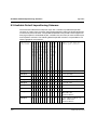
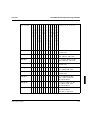
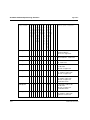
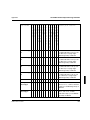
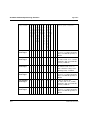
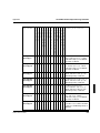
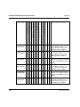
Available Default Impositioning Schemes................................................................ 116
Index .............................................................................................................................. 129
A29247-X21-X-6-7670
Introduction
Overview
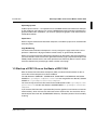
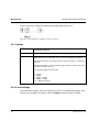
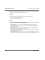
1 Introduction
1.1 Overview
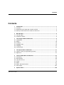
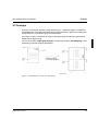
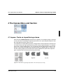
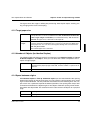
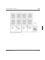
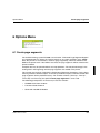
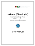
To cost-effectively produce the short press runs usually associated with Printing on Demand you need a highly automated process. The Professional Document Composer meets
this demand. This state-of-the-art prepress application performs the imposing of files that
have been converted into the print format. The program not only makes optimal use of the
print format; it also adjusts the page sequence during printing to the selected type of binding.
The Professional Document Composer is a highly flexible software product that works with
the POD-Module and all DEMANDSTREAM printers, both for cut sheet and continuous
forms processing. As a multipurpose application it is also designed to accommodate the
most diverse post-processing methods, both offline and online.
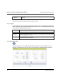
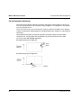
Figure 1
A29247-X21-X-6-7670
Integration of the Professional Document Composer into the PoD workflow.
1
Requirements for Operation and Use of PDC
Introduction
When you use the Professional Document Composer to imposition files, the print file is automatically adjusted to the type of:
•
Printed material
•
Print output
•
Post-processing
You’ll find The Professional Document Composer useful in a diversity of ways:
•
Accommodates wide range of publications.
•
Optimizes printing of small-format printed materials and thereby shortens printing
times.
•
Simplifies job preparation and job acquisition.
•
Facilitates seamless post-processing after the printing process.
•
Reduces paper costs.
•
Helps you fit the printed materials and the PoD process to your preferences, not the
other way around.
•
The Professional Document Composer provides a command-based as well as a graphical user interface.
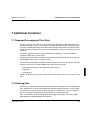
1.2 Requirements for Operation and Use of PDC
Format of input files
Input files for the Professional Document Composer must be provided in the MODCA format. Files in the following formats can be converted into MODCA by the POD-Module converters: PDF, PostScript, EPS, TIFF, PCL5 and PCL 6. These converted files can then be
processed by the Professional Document Composer. Restrictions apply to other MODCA
files from other converters or filters.
Naming conventions for input files
Input, output and resource files must not include the following characters as part of a file
name:
'!'
'<'
'>'
'$'
'*'
'/'
'%'
','
'"'
These are internal special characters of the Professional Document Composer.
2
A29247-X21-X-6-7670
Introduction
Start-up of PDC V3.xx on the Basis of PDC V2.0
Operating System
Caldera Opern Linux 3.1.1 is required to run the PRISMA Professional Document Composer with graphical user interface. To use the PRISMA Professional Document Composer in
graphics mode under X-Windows, you need an appropriate graphics card and monitor for
1024x768 resolution.
Paper Sizes
When using the Professional Document Composer, consider the paper sizes accommodated by the printer.
Page Numbering
The Professional Document Composer in no way changes the page content that’s to be
printed in a document. All page numbers remain exactly as generated by the editor.
When you use the Professional Document Composer for documents with page numbering,
you must therefore make sure that the generation of blank pages (especially in duplex and
folded printed materials with a front cover printed on one side only) doesn’t result in inconsistencies between the printed page number and the actual page.
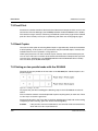
1.3 Start-up of PDC V3.xx on the Basis of PDC V2.0
With the Professional Document Composer (PDC) version 3.0 the directories for the resource files of the composer have been modified.
The old directories ’$MERGE’, ’$OVERLAYS’, $VARIABLE’ and ’$MARKS’ and $COMPOSER in u/prismapro/composer/resource have merged into one directory ’$COMPOSER’ in /u/prismapro/resources/composer.
You have to copy all resource files stored in the old directories under u/prismapro/composer/resource into the new directory ’$COMPOSER’ in u/prismapro/resources/
composer.
If you start the PDC V3.0 with a parameter file (from the graphical user interface or from the
command line), which still uses the old names of the resource files, the resources will automatically be taken from the ’$COMPOSER’ directory. Therefore you don’t have to modify
anything.
A29247-X21-X-6-7670
3
Start-up of PDC V3.xx on the Basis of PDC V2.0
4
Introduction
A29247-X21-X-6-7670
Main Window
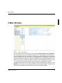
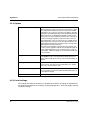
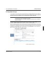
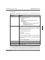
2 Main Window
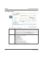
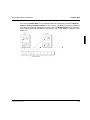
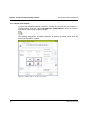
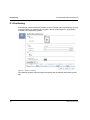
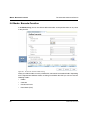
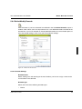
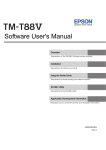
Figure 2
Composer Main Window
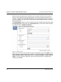
You can select one of the three main function groups Integrate, Impose and Assemble on
the left side of the PDC main window (Navigation Area). All applications which belong to
these components are then displayed in a second row of the Navigation Area. Clicking on
one of the components, opens the corresponding application in the Workspace Area on the
right side of the PDC. Here you can insert and modify the corresponding parameters. If parameters have been inserted or modified, the color of the corresponding symbol gets darker. If the changes have been applied, a green check mark is added to the symbol.
The File menu contains functions for managing, saving and organizing parameter sets. The
Options menu contains the possibility to generate internal page segments to fully use the
'Enhanced Page Segment Support' function of the Demandstream 8090.
A29247-X21-X-6-7670
5
Main Window
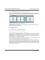
The fields Integrate, Impose and Assemble as a group serve to define the logical workflow
within the Professional Document Composer.
Integrate
This group contains all "logical operations", i. e., all functions that manipulate the print file
on the logical page level prior to the actual imposition. This includes multi color processing
(Highlight color), the insertion and deletion of pages (Merge), page cropping (Cropping),
and the insertion of Overlays and of Variable data.
Impose
Once prepared in this manner, the file can then be imposed, i. e., the page sequence and
page layout can be changed. The corresponding settings are selected in the Impose group
with the functionality of Impose and Signature.
Assemble
The third group provides the means of processing the output resulting from Integrate and
Impose on the physical page level. Assemble functions include the moving of logical pages
on the physical sheet (Positioning and Creep) and the insertion of Blank Sheets, Marks
and Barcodes. In addition, a print range (Print Range) can be defined and the individual
sheets can be assigned to the paper input trays of a cut sheet printer.
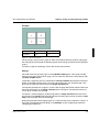
If you don't make any parameter settings, the default applies. In that case no Integrate and
Assemble parameters are selected.
The Impose parameters N-up, Page-Sequence, Page layout and Paper size are set to
the value from file. This means that the page sequence as well as the page layout and the
target paper size are retrieved from the input file.
6
A29247-X21-X-6-7670
Main Window
The File Menu
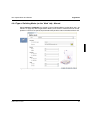
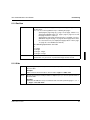
2.1 The File Menu
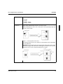
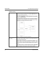
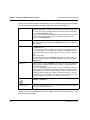
'Default'
This command generates a new parameter set with default settings.
All preceding entries that have not been saved with 'Save copy as'
are now deleted without a warning message.
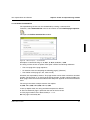
'Open’
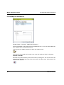
This command opens a file selection box for you to select the parameter set you want to load.
The File Selection Box displays all files in the currently selected directory.
You can change directories either by double-clicking an element in
Directories or by entering the name in the input field Filter and
clicking the Filter Button once. You can select a parameter set in
the Files list. You can also enter the fully qualified name of the parameter in the Selection input field.
Click the OK button to load the selected file and return to the previous window. Cancel aborts the file selection and returns to the PDC
main window.
'Save the parameter set'
Clicking this button displays the 'Save' file selection box along with
the listof the parameter sets already stored in the 'Home' directory.
The Professional Document Composer always automatically adds
the suffix '.imp' tothe set name, if you haven't already done so.
Please be aware that the Composer will add a suffix if such a suffix
has already been inadvertently entered in capital letters ('.IMP'),
since the Composer would identify these as part of the name (e.g.,
'xxx.IMP.imp').
'Save the parameter set as'
Allows you to save the parameter set under a different name.
'Comment’
This command opens a window in which you can edit a description
of your current parameter set.
A29247-X21-X-6-7670
7
Common Controls
Main Window
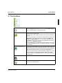
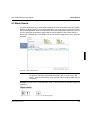
2.2 Common Controls
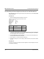
2.2.1 List of settings
To accept settings made in the input fields, they must be stored in the list of settings before
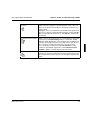
pressing 'Apply'. These lists appear in most of the applications of the Professional Document Composer. The following icons are used to manipulate the list of settings:
Add new Item
Inserts settings from the input fields into the list.
Remove selected items
from the list
Removes a previously selected line from the list.
Modify the item
Select the line which should be modified. Now you can modify the
entries in the input fields. Then click the icon to change the setting in
the list accordingly.
Move selected items up
Moves a selected entry up in the list.
Move selected items down
Moves a selected entry down in the list.
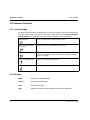
2.2.2 Buttons
8
Apply
Accepts all modified settings.
Cancel
Discards all modifications.
Clear
Clears all text fields.
Help
Opens the context sensitive help file for the active application.
A29247-X21-X-6-7670
The Integrate Menu and Section
Introduction
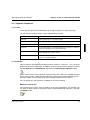
3 The Integrate Menu and Section
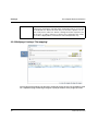
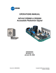
Figure 3
’Integrate’ section
3.1 Introduction
Here the document is manipulated on the logical page level. You may define custom tone
printing, insert, replace and delete pages, cut out printable areas, place overlays or variable
data. The respective functions are Merge (page 10), Overlays (page 13), Highlight Color
(page 19), Cropping (page 22) and Variable data (page 25).
A29247-X21-X-6-7670
9
Merge
The Integrate Menu and Section
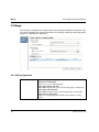
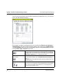
3.2 Merge
The functions available in this window enable you to directly manipulate the print file. The
file can be adapted to the current requirements by inserting, removing or replacing logical
pages in the document as required.
Figure 4
Window ’Merge’
3.2.1 Define Operation
’Select action’
The following actions are possible:
Delete one or more pages:
Deletes one or more selected page(s).
Insert pages before selection:
Adds additional pages before the selected target page of the print file.
Insert pages after selection:
Adds additional pages after the selected target page of the print file.
Replace one or more pages:
Replaces the target pages specified with selected pages or blank
sheets.
10
A29247-X21-X-6-7670
The Integrate Menu and Section
’Choose target pages’
Merge
Enter the target page(s), which should be deleted, inserted or replaced.
"n" represents the last page of the file, "n-1" the second-last page, etc.
The following expressions are valid:
n
n-integer
n/integer
n/integer - integer
integer
integer - integer
integer - n
integer - integer : integer (if 'Insert pages before selection')
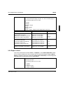
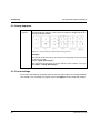
Examples
Operation
Target pages
Delete page 8
Delete pages 1 through 8:
Delete the second half of the print file
Delete the first half of the print file
Delete one or more pages
Delete one or more pages
Delete one or more pages
Delete one or more pages
8
Insert before the second-last page:
Insert after the last page
Insert in the middle of the print file
Insert before every page
Insert before every second page
Insert pages before selection
Insert pages after selection
Insert pages before selection
Insert pages before selection
Insert pages before selection
n-1
n
n/2+1
1-n
1-n:2
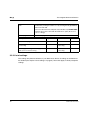
Replace pages 8 to the end of the file
Replace second half of the print file
Replace one or more pages
Replace one or more pages
8-n
n/2+1-n
1-8
n/2+1-n
1-n/2
3.2.2 Pages to insert
If you have selected the functions Insert... or Replace... in the Define Operation section,
you can choose whether to insert or replace one or more blank (logical) page(s) (Blank
pages) or whether pages from another file (Pages from source file) are to be integrated
in the document. The file must be in the IOCA format.
’Set page range’
The number of pages or the range of pages to be inserted or replaced is
defined in this field.
The following expressions are valid:
n
n - integer
n / integer
n / integer - integer
n / integer + interger
A29247-X21-X-6-7670
11
Merge
The Integrate Menu and Section
’Pages from source
file’
If pages from another file are to be inserted in the document, you can select the file by clicking the folder icon or by entering the fully qualified file
name in the text field.
The source files must be stored previously in the directory $COMPOSER
in IOCA-format. This is done with the PJM 'Store' option (Store as resource -> Merge).
’Blank pages’
Inserts blank pages at the given position.
Examples
Pages
Source file
Number
Insert 3 blank pages
Blank
Insert page 3 from file /$COMPOSER/
source.mrg
from file
/$COMPOSER/
source.mrg
3
Insert pages 3 through the last page from
file /$COMPOSER/source.mrg
from file
/$COMPOSER/
source.mrg
3-n
3
3.2.3 List of settings
The settings only become effective, if you add them to the list of settings at the bottom of
the window (see chapter ’List of settings" on page 8). Then click ’Apply’ to finally accept the
settings.
12
A29247-X21-X-6-7670
The Integrate Menu and Section
Overlays
3.3 Overlays
Overlays are useful for inserting a static element (e.g., a corporate logo) in an otherwise
completed page. The Professional Document Composer features options for inserting your
own overlays on any desired page(s) in the document.
An overlay is always inserted at the origin of the logical page and remains permanently
linked with the logical page.
You can insert either single page overlays or multi page overlays (File mapping). A free
positioning is possible for both possibilities.
Figure 5
A29247-X21-X-6-7670
Static linking of the overlay with a logical page.
13
Overlays
The Integrate Menu and Section
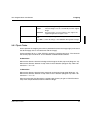
3.3.1 Single Overlays
Figure 6
Window 'Overlays' – 'Single overlays'
’File Selection’
You can select an overlay file by entering the fully qualified file name in the Selection text field or by clicking the folder button, which opens a File Selection
Box
Overlay resource files must reside as 1-page IOCA files (suffix '.ovl') or as multipage IOCA-files (suffix '.map') in the '$COMPOSER' directory. The resource
generation must be performed with the Print Job Manager (PJM).
’Target Pages’
Here the pages are set, where the overlay is placed onto. There are various
possibilities to define a target page:
On single pages:
on page 8 and 10: 8,10
on the last page: n
On pages within a range:
on page 1 to 20: 1-20
on page 8 to the one before last: 8-n-1
On pages within a range in steps:
on page 1 to 20 on every second page: 1-20:2
14
A29247-X21-X-6-7670
The Integrate Menu and Section
Overlays
The following expressions are valid:
n
n - integer
n / integer
n / integer - integer
n / integer + integer
’Position/X’
’Position/Y’
The selected overlays may be positioned freely on the print page by setting x
and y values. Valid formats are mm, cm, inches or Pels.
Without defining those values, the overlay is put on the logical page origin (upper left corner portrait):
Figure 7
Positioning without offset values
If positioning values are set, the overlay is moved relatively to the logical page
in x and y direction.
Attention: The positioning starts at the logical page origin and not at the origin
of the pysical page. This is imortant, if the images are rotated. In this case the
X and the Y axis for the overlay positioning is also rotated.
Figure 8
A29247-X21-X-6-7670
Positioning with offset values
15
Overlays
The Integrate Menu and Section
’Color Selection’
’Set color’
If this box is checked, the selected overlay is printed in another color instead
of the default color. Next to the check box you can select a specific color for
the overlay from a combo box. The list of settings shows the respective color
in the ’Color of overlay’ column. If no special color is selected for the overlay
’From file’ is displayed here. This function works with IOCA files only.
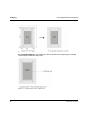
3.3.2 Multipage Overlays ’File mapping’:
The merging of the original print file with a multipage overlay file may for example be used
for a sequential page numbering throughout a print job made of many single input files.
16
A29247-X21-X-6-7670
The Integrate Menu and Section
Overlays
’Selection’
As with single overlays (see above).
’Pages’
Insert individual pages or page ranges of the multipage overlay file, which
should be placed on the pages of the print file.
Inserting in individual pages:
On page 8: 8
On the last page: n
Inserting in pages within a range:
On pages 1 through 20: 1-20
On pages 8 through the second-last page: 8-n-1
Inserting in pages within a range, but in interval steps:
Within a range of 1 through 20 on every second page: 1-20:2
The following expressions are valid:
n
n - integer
n / integer
n / integer - integer
n / integer + integer
’Target page’
Using multipage overlays, only a single page may be defined as target page,
because the selected overlay pages are always inserted in one block starting
with the target page.
on page 8: 8
in the middle of the document: n/2
on the fifthlast page: n-5
on the last page: n
Figure 9
Merging a print file with page numbering (from page 3)
The following expressions are valid:
n
n-integer
n/interger
n/integer-integer
n/integer+integer
’Position/X’
’Position/Y’
A29247-X21-X-6-7670
As with single overlays (see above).
17
Overlays
The Integrate Menu and Section
3.3.3 List of settings
The settings only become effective, if you add them to the list of settings at the bottom of
the window (see chapter ’List of settings" on page 8). Then click ’Apply’ to finally accept the
settings.
18
A29247-X21-X-6-7670
The Integrate Menu and Section
Highlight Color
3.4 Highlight Color
This option allows you to use colors to highlight graphical (e.g a company logo) or text information. The 2-color print merges two (or more) pages with different colors applied. These
pages may be part of the print file itself (See ‘From mapping file') or come from two different
files (See 'From input file'). This function works with IOCA files only.
Figure 10
Highlight Color - File mapping
’File Mapping'
If File Mapping is selected (’Tone Settings’ -> ’From input file’ is deactivated), a resource file is printed as colored overlay on the print file.
'Selection'
The selection of a 'mapping file' may be done by entering the fully qualified file name in the field Selection or by pressing the folder icon, which
opens a 'File Selection Box'.
Mapping resource files for Highlight Color have to be saved with the
ending .hlc in the directory $COMPOSER
A29247-X21-X-6-7670
19
Highlight Color
’Pages'
The Integrate Menu and Section
If a mapping file is used, single or multiple pages may be selected to be
used for custom tone printing. The following entries are allowed:
Selection of a single page: Page 8, last page: n
Selection of a page range: page 8 to the page before last: 8-n-1
The following expressions are valid:
n
n – integer
n / integer
n / interger – integer
n / integer + interger
’Target page'
Here the target page is defined, from where the mapping file is to be
used. Only a single page entry is allowed, because the mapping file is
always merged as block.
The following expressions are valid:
n
n – integer
n / integer
n / interger – integer
n / integer + interger
’Position/X’
’Position/Y’
The mapping file may be positioned freely on the print file, always relating to the print origin of the print file itself. the X and Y values may be
entered in mm, cm, inches or Pels.
’Options’
You can use this combo box to select a specific spot color apart from
’Brown (Alternate Colour)’ or ’Printer default’ (usually Black).
Note: The selected printer must support this feature (e.g. VS9000).
20
A29247-X21-X-6-7670
The Integrate Menu and Section
Figure 11
Highlight Color
Highlight Color - From input file
'From input file'
If the option From input file is activated, the input file must be already
in a format, which supports multi color printing. In these files the colors
of the images are still separated, i.e. each of the single pages contains
the image information for one specific color.
Using this mode, you can assign a specified color to each page (color
separation) within the ’set’. The PDC then overlays all pages of one set,
which belong together to create one logical page of the output document. Consequently the number of pages of the output document results from the number of pages of the input document / number of pages
of one ’set’ (or the number of active color separations).
The maximum number of pages per set is restricted to 5.
3.4.1 List of settings
The settings only become effective, if you add them to the list of settings at the bottom of
the window (see chapter ’List of settings" on page 8). Then click ’Apply’ to finally accept the
settings.
A29247-X21-X-6-7670
21
Cropping
The Integrate Menu and Section
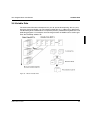
3.5 Cropping
The Cropping function enables you to trim IOCAs prior to imposition. This is desirable, for
example, when the crop marks present in the data file must not be printed.
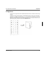
You can choose any size of cropping area. There are two ways of positioning the area: centered to the image (Center) or originating from the object origin (Standard).
22
Figure 12
Window ’Cropping’
Figure 13
Comparison between 'centred cropping' and 'standard cropping'
A29247-X21-X-6-7670
The Integrate Menu and Section
’Object area’
Cropping
You have two ways of cutting an image out of the document:
center
standard
’Extent in direction’
The new image is cut out concentrically from the original
image.
The new image is cut out in relation to the origin of the
original image in the left upper corner.
The extent of the cropped image is defined by the X-Extent and Y-Extent.
Click OK to confirm all settings or click Cancel to disregard all changes.
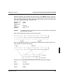
3.5.1 Tips & Tricks
How to position the cropping area with any desired offset from the image origin (in the event
the desired page area is not concentric with the image):
Convert the data file (e.g., PS or TIFF file), specifying "variable paper size". The values for
the correct paper size in the X- and Y-direction are determined as follows:
X-dimension:
Measure the distance from the left edge of the image to the left crop mark (Diagram: X1).
Measure the distance between 2 crop marks in the X-direction (Diagram: X2). New X-dimension: 2 * X1 + X2
Y-dimension:
Measure the distance from the lower crop mark to the lower image edge (Diagram: Y1).
Measure the distance between 2 crop marks in the Y-direction (Diagram: Y2). New Y-dimension: 2 * Y1 + Y2.
After converting the data file with this variable paper format, you get an IOCA file whose
crop marks are positioned concentric within the image.
A29247-X21-X-6-7670
23
Cropping
The Integrate Menu and Section
Figure 14
Conversion with variable paper size
Set 'centred cropping' in the Composer, with the extent of the cropping area selected
small enough to hide the crop marks.
Figure 15
24
Centred position of the cropping area
A29247-X21-X-6-7670
The Integrate Menu and Section
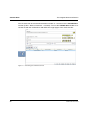
Variable Data
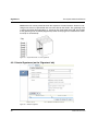
3.6 Variable Data
The Professional Document Composer let's you do "personalized printing" the easy way.
Using the overlay technique, you can include variable data (e.g., addresses) in documents.
The formatting of the variable data is an upstream process, performed using databases and
publishing programs. For example, the mail-merge function in WORD can be used to generate the PostScript address file.
Figure 16
A29247-X21-X-6-7670
Window ’Variable Data’
25
Variable Data
The Integrate Menu and Section
This file must then be converted and made available as a resource for the Variable Data
function (PJM -> Store as Resource -> Variable). You use the Variable data window to select the file with the variable data and define the target pages of the static data file:
Figure 17
26
Generating personalized documents
A29247-X21-X-6-7670
The Integrate Menu and Section
Variable Data
The function Variable data may be combined with the impositioning schemes Identical
copies or Two Up & Identical copies. In this case the variable data will not be copied but
each data set will be printed only once. In the case of 2 Identical copies each sheet contains 2 logical pages with two different data sets (i.e. copy 1 with address 1 and copy 2 with
address 2).
Figure 18
A29247-X21-X-6-7670
Combination of variable data and "Two Up & Identical copies"
27
Variable Data
The Integrate Menu and Section
Window Functions
’Selection’
You can select a variable data file by entering the fully qualified file
name in the ’Selection’ text field or by clicking the Select files button,
which opens a File Selection Box.
The variable data file must be available in IOCA format in a resource library under $COMPOSER. The resource generation is performed by
the Print Job Manager (PJM).
The variable data file must be page-oriented, with each page in this file
containing exactly one variable record (e.g., an address). In addition,
the pages are correctly formatted, so the variable records are correctly
positioned on the static document after the overlay.
Figure 19
’Target pages (increasing order)’
Merging of a document with variable data
Here, you define the pages on which the variable data is to be placed
(e.g., page 1, page 5, page 9 - pattern: 1,5,9). The page numbers must
be entered in increasing order.
In this example, the first page of the variable data file (address 1) was
placed on page 1 of the static document; the second address on page
5 of the static document; and the third address on page 9. As a result,
the first copy of the output file contains 3 variable records on pages 1, 5
and 9.
The variable records 4, 5 and 6 are inserted on the first, fifth and ninth
page of the second copy, etc. In this manner, the entire variable data file
is sequentially processed until all records have been inserted.
28
A29247-X21-X-6-7670
The Integrate Menu and Section
Variable Data
The following expressions are valid:
n
n - integer
n / interger
n / integer - integer
n / integer + integer
Integer * n
Interger * n / integer
Interger * n / integer+integer
Interger * n / integer-integer
’Exemplars’ (Copies)
Here the selection of copies (relating to data sets) may be done.
The Default setting is 1-n (all exemplars with all data sets will be used)
If a single exemplar is selected, one print sheet is printed in the case of
identical copies with the selected datasets (in case of duplex we would
have 4 data sets on a sheet with 4 logical pages)
In case of multiple exemplars the above single setting is used for the
chosen range.
The following expressions are valid:
n
n-integer
n/interger
integer*n/integer
’X’ / ’Y’
The selected variable data may be positioned freely on the logical pages of the print file itself (details see in 'Overlays').
3.6.1 List of settings
The settings only become effective, if you add them to the list of settings at the bottom of
the window (see chapter ’List of settings" on page 8). Then click ’Apply’ to finally accept the
settings.
A29247-X21-X-6-7670
29
Variable Data
30
The Integrate Menu and Section
A29247-X21-X-6-7670
The Impose Menu and Section
Impose: Create an impositioning scheme
4 The Impose Menu and Section
4.1 Impose: Create an impositioning scheme
Here the actual Impositioning of the print file is applied, i.e. the logical pages are placed
on the print sheets accordingly. Important parameters are Layout (simplex, duplex or tumble, impositioning scheme paper size etc.
The selection of an impositioning scheme strongly relates to the output form (continuous or
cut sheet) and on the paper post processing. The variety of printed material, i.e. different
sheet sizes, various binding forms, etc. are already to be considered while setting up the
print file. The Professional Document Composer places the logical pages in such a way,
that the reading sequence of the document remains indifferent in spite of the sequence
gaps and jumps due to the post processing (see below).
Figure 20
A29247-X21-X-6-7670
Print order of logical pages dependant on the selected post processing
31
Impose: Create an impositioning scheme
The Impose Menu and Section
With the Professional Document Composer you can impose continuous forms paper or
sheets to suit the post-processing requirements. The system provides 70 ready-to-use
schemes, complete with production flow displays for the most important types of post-processing. In addition, you can create custom schemes with complete freedom in choosing
page arrangements.
The Impositioning window is where you define the layout and impositioning scheme (Layout and sequence), target paper size (Target paper size) as well as the number of copies
for "Identical copies" (Number of objects).
Figure 21
Window 'Impose'
When you are sure that all parameters have been completely entered, click Apply to confirm the settings and return to the main window. If you have forgotten to enter the spacing
(Space between origins in direction X and Y) with Identical copies or 2up & identical
copies, an error message is displayed, "Input for spacing not found". To disregard all
changes click Cancel.
32
A29247-X21-X-6-7670
The Impose Menu and Section
Impose: Create an impositioning scheme
4.1.1 Layout & Sequence
4.1.1.1 N-UP
In this field you determine the distribution of the logical pages on the physical page.
You can choose among a variety of basic impositioning schemes:
’From file’
Accepts the setting that exists in the document (default setting).
’One Up’
One logical page on one physical page
’Two Up’
Two logical pages on one physical page (e.g., page 1 and 2)
’Three Up’
Three logical pages on one physical page (e.g., page 1, 2 and 3)
’Four Up’
Four logical pages on one physical page (e.g., page 1, 2, 3 and 4,
always positioned in the clockwise direction).
’Identical Copies’
One logical page arranged several times, parquet-fashion, on one
physical page (e.g., page 1 twice)
’Two Up & Identical Copies’
Combination of two up and Identical copies (e.g., pages 1 and 2
twice on one physical page).
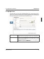
4.1.1.2 Scheme
This list contains all predefined standard schemes (scheme 1, scheme 2, ...etc. ) for the imposition mode set up under N-UP. In addition, it lets you create custom schemes by selecting user defined and command line and clicking the Define page sequence button:
When you move the mouse pointer to a scheme entry on the open list, a bubble-help box
opens which contains a brief comment about the scheme type and the related post-processing workflow. This will help you to find a suitable scheme quickly in the list.
You can define your own schemes in addition to the ones provided.
Modify the scheme list
The scheme list isn’t static. You can modify it to suit your requirements. For example, you
can enter or delete entries or change the name and the bubble-help comments. Just click
the Modify button:
A29247-X21-X-6-7670
33
Impose: Create an impositioning scheme
The Impose Menu and Section
The scheme list pertaining to the selected impositioning method opens (e.g., the scheme
list for Two Up & Identical Copies):
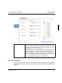
Figure 22
Window 'Impose' - 'Modify the scheme list'
Each scheme on the list is displayed with name, scheme type (default, user defined or
command line) and layout (simplex, duplex, tumble). The scheme types command line
and user defined indicate that the corresponding schemes have been defined by the user
through Define page sequence (see below).
34
’Rename the scheme’
If you wish to rename one of your schemes, highlight it with the
mouse pointer. The existing name is displayed in the text field Selection. Type in the new name in the box underneath. Click the Rename the scheme button to confirm the new name.
’Remove selected items
from the list’
To remove one or more elements from the list, select them with the
mouse pointer and then click the Delete the current scheme button.
Caution: Once user-defined schemes have been deleted, they cannot be restored!
’Move selected items up/
down’
Click Move selected items up or Move selected items down to
move any one or any group of selected elements up or down on the
list, one notch at a time. In this manner you can change the sequence of the schemes to suit.
A29247-X21-X-6-7670
The Impose Menu and Section
Impose: Create an impositioning scheme
’Restore the default list of
schemes’
Click Restore the current default schemes to load the default
scheme list. The sequence of entries keeps the same. If the comments of the default schemes differ to the default comments, they
will be saved.
During this action you will therefore be asked by the program if you
are sure you want to load the default scheme list. Confirm with Apply to load the default scheme list, or click Cancel to keep the list
unchanged.
’Comment current scheme’
When you move the mouse pointer across the elements of the open
scheme list in the Impositioning window, a small, blue "bubblehelp" box will be displayed for each scheme in turn. In addition to information about page sequence, layout and scheme type, the box
also contains a comment about the type of post-processing.
You can edit this comment in the text field Comment or, if the
scheme is user-defined, regenerate it. Click Comment current
scheme to link the comment with the selected scheme.
’Copy current scheme’
By entering a new name in New name you are able to copy a selected scheme to the new scheme. Thus the newly created scheme gets
the same properties (layout, type etc.) as the original, except for the
name.
A29247-X21-X-6-7670
35
Impose: Create an impositioning scheme
The Impose Menu and Section
4.1.1.3 Define User Scheme
If none of the standard imposition schemes is suitable for your print job, you can define a
custom scheme. To do this, select user defined or command line in the list of schemes
and click the ’Define page sequence’ button:
The following dialog opens. The title bar indicates, for which n-up setting and for which layout the scheme will be created:.
Figure 23
36
Window 'Impose' – 'Define user scheme'
A29247-X21-X-6-7670
The Impose Menu and Section
Impose: Create an impositioning scheme
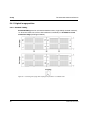
Preparation:
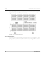
First decide how the pages are to be sequenced in the file you want to impose.
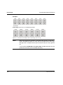
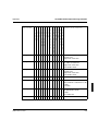
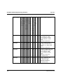
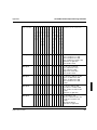
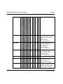
Example:
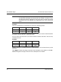
Document with 32 pages. The pages are to be printed in two up, duplex mode in the following sequence:
Print sheet
Front page
Back page
1
1, 17
18, 2
2
3, 19
20, 4
3
5, 21
22, 6
4
7, 23
24, 8
5
9, 25
26, 10
6
11, 27
28, 12
7
13, 29
30, 14
8
15, 31
32, 16
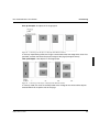
Figure 24
Example file with 32 pages (Two Up, Duplex)
Next, decide on the repetition mode – i.e. the number of physical pages (front and back
pages) after which the pattern is to be repeated. (The "pattern" defines how the logical pages from the print file are arranged on the physical sheets.)
In the above example, the pattern is repeated after two physical pages. This is one print
sheet, because the example application is duplex. The repetition mode is therefore 2.
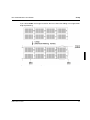
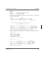
The logical pages on the second and all following sheets are arranged according to the
same pattern as on the first. The only difference between them is the page numbering. Each
number is incremented by a positive or negative integer value (the distance value).
If you view the first logical page in the repetition group, you see that the first front page
contains page 1, the second contains page 3, the third contains page 5, .... etc.
A29247-X21-X-6-7670
37
Impose: Create an impositioning scheme
The Impose Menu and Section
There is a distance (spacing) value of 2 between each page.
Determine the distance values between all the logical pages in the group to be repeated. In
the above example, the group contains two logical pages with the distance values 2, 2, 2, 2.
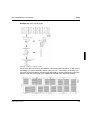
Figure 25
Calculation of 'distance' and 'repetition mode'
'Repetition mode' and 'Distance' values are needed to edit the selected scheme in the
Professional Document Composers.
Logical page selection
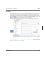
Figure 26
Window 'Impose' – 'Define user scheme' - 'Image selection'
Depending on what repetition mode you have set for Physical sheet options, the Image
selection field lists enough logical pages (repetition mode * 4) for you to place them in the
Page options field according to the required imposition scheme. If the repetition mode is
2, for example, 2 x 4 = 8 pages will be shown.
When creating your own scheme, you are in fact working with a type of template file which
contains a number of pages equal to the repetition mode x 4.
Since a real print file will usually contain more pages than the template, you next have to
transfer the page sequencing of the real file to the template file, i.e. the imposition scheme
for the real print file must now be applied to a file with a number of pages equal to the repetition mode x 4. You need not perform this action for the entire print file – just for the pages
in the repetition mode range:
38
A29247-X21-X-6-7670
The Impose Menu and Section
Impose: Create an impositioning scheme
Example:
Print file:
1, 17
18, 2
Template:
1, 5
6, 2
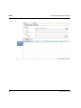
Figure 27
Impositioning model
The last page in the print file is page 32. Since this template file only contains eight pages,
the real page 32 corresponds to template page 8; the real page 16 corresponds to template
page 4.
To select a page for positioning, click it with the left mouse button.
Settings
This field shows the physical pages in the repetition mode group. If the group includes
more than one front and one back page, you can select the sheet you want to display with
the Sheet number option.
To position a page that you have selected in the Image selection field, click the left mouse
button on the empty field in which you want to place the page. The selected page is displayed in this field and removed from the Image selection field.
To undo the placement of a page on a sheet, click the page with the left mouse button and
then click the dust bin in the Image selection field. The page is moved back into the list
and is again available for selecting.
To replace a selected page by another page from the Image selection field, click the required page in the Image selection field and then click the page you want to replace in Settings. The two pages are then exchanged.
During the placement of the logical pages, the system checks if the sequence is correct. A
message will be displayed accordingly in the Settings section ("Right page sequence",
"Wrong page sequence").
A29247-X21-X-6-7670
39
Impose: Create an impositioning scheme
The Impose Menu and Section
You can set an angle of rotation and distance value for each logical page that you position.
The rotation is displayed above the logical page, the distance value below it.
’Repetition mode’
Use this option to set the repetition mode you have decided to use (see
chapter "Preparation:" on page 37). The repetition mode specifies the number of physical pages to be printed before the pattern repeats itself (using
the incremented distance values).
For two-up mode, the maximum repetition mode is currently 4. If you require
a more extensive range to describe your scheme, you must enter the
scheme as a command line.
’Sheet number’
Use this option to select the number of the physical page you want to display. This page is then displayed in the Settings field and can be assigned
logical pages.
’Rotation’
Use this option to specify the rotation of the logical page that is the focus in
the Settings field.
You cannot assign angles of rotation until you have completed your selection of logical pages, i.e. all fields in the repetition mode range must be assigned logical pages. The possible angles of rotation are 0°, 90°, 180° and
270°.
Proceed as follows:
Select the required page in the Settings field. Then choose the angle of rotation from the Rotation list. The angle is displayed above the page in the
Settings field.
’Distance’
Use this option to assign a distance. The distance is the spacing between
a given logical page in the repetition group and the corresponding logical
page in the next group.
You cannot assign distance values until you have completed your selection
of logical pages, i.e. all fields in the repetition mode group must be assigned
logical pages. If there is only one pair of distance values suitable for the selected page sequence this pair of values is displayed. If there are several
possibilities, you can select the one you wish to use from a list. The correct
prefix is assigned automatically – you need not set it yourself.
’Delete all settings’
Use this option to delete the settings you have made for Image selection,
Rotation and Distance.
’Scheme name’
Before you exit the window, you must assign a name to your new scheme.
Enter the name in the text field.
Click Cancel to return to the previous window without saving your parameters, or OK to
confirm your entries and return to the previous window. The new scheme appears as a new
entry in the list of schemes.
40
A29247-X21-X-6-7670
The Impose Menu and Section
Impose: Create an impositioning scheme
4.1.1.4 Define Command line
The impositioning scheme can also be defined by entering a command line.
To do this, select Command line in the list of schemes and click Define page sequence:
This opens the Define command line window.
Figure 28
Window 'Impose' – 'Command line'
Example of a command string: n, -2, 90, 1, 2, 90, 2, 2, 90, n-1, -2, 90
The string consists of sets of triplets. Each triplet contains the following definitions:
•
The start page of the page sequence
•
An absolute value for computing the following page(s) (distance)
•
The rotation of the page (0°, 90°, 180° or 270°)
All entries are separated by commas. The page number can be either a relative or absolute
number. The character "n" is always the final page number, and this number includes any
blank pages which the Professional Document Composer appends to the end of the document.
The string in the above example contains four triplets:
n,-2,90, and 1,2,90, and 2,2,90, and n-1,-2,90
In two-up duplex mode, the string would be interpreted as follows:
n: The last document page is printed on the front of the first sheet.
-2: This page number is then decreased by 2 --> n-2.
90: The page is rotated by 90°.
A29247-X21-X-6-7670
41
Impose: Create an impositioning scheme
The Impose Menu and Section
1: The first document page is printed on the front of the first sheet.
2: This page number is then incremented by 2 --> 3.
90: The page is rotated by 90°.
2: The second document page is printed on the back of the first sheet.
2: This page number is then incremented by 2 --> 4.
90: The page is rotated by 90°.
n-1: The penultimate document page is printed on the back of the first sheet.
-2: This page number is then decreased by 2 --> n-3.
90: The page is rotated by 90°.
The first sheet is now complete. On the front are document pages n and 1; on the back are
document pages 2 and n-1.
The sequence is repeated on all subsequent sheets. In each cycle, the new page number
is obtained by adding the distance (spacing) value to the page number obtained from the
preceding cycle.
The second sheet would contain the following pages:
n-2: Document page n-2 is printed on the front of the second sheet.
-2: This page number is then decreased by 2 --> n-4.
90: The page is rotated by 90°.
3: Document page 3 is printed on the front of the second sheet.
2: This page number is then incremented by 2 --> 5.
90: The page is rotated by 90°.
4: Document page 4 is printed on the back of the second sheet.
2: This page number is then incremented by 2 --> 6.
90: The page is rotated by 90°.
n-3: Document page n-3 is printed on the back of the second sheet.
-2: This page number is then decreased by 2 --> n-5.
90: The page is rotated by 90°.
In summary: on the front of the second sheet are document pages n-2 and 3; on the back
are pages 4 and n-3.
42
A29247-X21-X-6-7670
The Impose Menu and Section
Impose: Create an impositioning scheme
Relative page numbers
Relative page numbers can be specified in the string as follows:
n
n-integer
n/integer
n/integer+integer
n/integer-integer
integer*n
integer*n/integer
integer*n/integer+integer
integer*n/integer-integer
Number of triplets
Specify as many triplets as there are pages on the sheet. This number depends on the print
mode and imposition scheme (1up, 2up, 3up, 4up or identical copy). The following numbers
of triplets are recommended, but you can define a different number if you wish:
One-up or identical copy with simplex:
one triplet
One-up or identical copy with duplex/tumble:
two triplets
Two-up and simplex:
two triplets
Two-up and duplex/tumble:
four triplets
Three-up and simplex:
three triplets
Three-up and duplex/tumble:
six triplets
Four-up and simplex:
four triplets
Four-up and duplex/tumble:
eight triplets
Two-up&Identical copy and simplex
four triplets
Two-up&Identical copy and duplex/tumble
four triplets
’Command line
sequence for
scheme’
You can select a scheme, which is available for n-up type and layout you have
chosen. Click the following button to transfer the page sequence of this
scheme to the command line:
You can then individually modify this scheme and save it under a new name.
’Scheme name’
A29247-X21-X-6-7670
Assign a name for your new scheme. Enter the name in the text field.
43
Impose: Create an impositioning scheme
’Command line
sequence’
The Impose Menu and Section
Enter the triplet needed for the new scheme (see description and examples
above).
Click Cancel to return to the previous window without saving your parameters, or OK to
confirm your entries and return to the previous window.
4.1.1.5 Layout
All standard schemes are firmly linked with one specific layout. The display merely indicates
which setting has been made for the selected scheme. If this is a user-defined scheme, you
can assign any desired layout to it here:
’From file’
Retrieves settings from the document.
’Simplex’
The sheet is only printed on one side.
’Duplex’
After being printed on the front side, the sheet is rotated about its left edge and is
then also printed on the back.
’Tumble’
After being printed on the front side, the sheet is rotated about its upper edge and
is then also printed on the back.
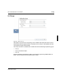
4.1.1.6 Show work flow
Click this button to view a graphical presentation of the scheme selected in the list of
schemes. The diagram shows the stages in the production workflow with this scheme.:
Figure 29
44
Window 'Impose' – 'work flow': Scheme1, two-up.
A29247-X21-X-6-7670
The Impose Menu and Section
Impose: Create an impositioning scheme
The figure shows the stages in offline post-processing: internal print output, stacking, cutting, merging of the stacks and stapling.
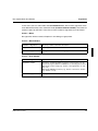
4.1.2 Target paper size
’Format’
In this field, define the physical target paper size on which the printed material is
to be produced. You can choose between sizes: A4, A3, A4 uncut, A3 uncut, B4,
Letter, Legal, Ledger and Variable (for user defined formats). With the default
from file, the paper size is retrieved from the input file.
’Width’ /
’Height’
The dimensions of the selected paper size are displayed in the fields X and Y. If
you have selected a variable paper size, you have to enter the exact dimensions
of the paper here. You can choose among the following units of measurement:
mm, cm, pel and inch.
The maximal paper size is 54 inches.
4.1.3 Number of Objects (for Identical Copies)
The following fields only become active if you select the layout Identical copies or Two up
& identical copies in the N-Up list. Here you can define the number and position of the
copies of logical pages.
’in X direction’
You need to define the number of images (or logical pages) you intend to have
arranged on the physical page. In this field , enter the number of copies in the Xdirection.
’in Y direction’
In this field , enter the number of copies in the Y-direction.
4.1.4 Space between origins
With Identical copies or Two up & identical copies you also need to define the spacing
between the images on the physical page. You can enter this value manually or by actuating the Calculator button. You may enter the measurements in the following units: mm, cm,
pel or inch. Use a period to separate the decimal positions. The spacing here always refer
to the distance between the object origins of two objects. Different spacing cannot be defined within one object field. The selected X and Y values relate to all objects on a physical
page.
’in X direction’
Spacing in the X-direction.
’in Y direction’
Spacing in the Y-direction.
A29247-X21-X-6-7670
45
Impose: Create an impositioning scheme
46
The Impose Menu and Section
Automatic
calculation of
spacing (X/Y)
This function automatically calculates the spacing between the images, after
their number has been defined in 'Number in directions'.
The following applies to the spacing of the object origin in the X-direction and the
Y-direction:
x-spacing = x-paper size / (number of copies in x-direction)
y-spacing = y-paper size / (number of copies in y-direction)
Example:
Selected paper size: A3 (≅ 29.7 cm x 42.0 cm)
Number of copies in x-direction: 2
Number of copies in y-direction: 3
x-spacing = 29.7 cm/2 = 14.85 cm
y-spacing = 42.0 cm/3 = 14.00 cm
Show example
Provides a general example of how the images are arranged on the physical
page.
A29247-X21-X-6-7670
The Impose Menu and Section
Signatures
4.2 Signatures
A signature is a large sheet, which is folded several times to form a section of a book, magazine etc.
A signature usually contains between 4 and 96 logical pages (in some cases 128 pages),
generally as a multiple of 4 logical pages, i.e. 4, 8, 16, 32 etc.The Composer lets you subdivide the printed document into any number of signatures of any length, and then lets you
impose these with a scheme of your choice (Signatures tab).
Figure 30
A29247-X21-X-6-7670
Signature sheet
47
Signatures
The Impose Menu and Section
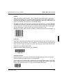
Additional marks can be printed to check the sequence of sorted sections. Known as collating marks, these are printed with the rest of the data on the sheets. The gathering mark
is always located on the gutter edge, i.e. exactly on the visible edge of the fold. The location
of the gathering mark is shifted progressively lower on the page. You create those marks
manually or automatically.
Figure 31
Sequential marks on seven signatures
4.2.1 Create Signatures (on the ’Signature’ tab)
Figure 32
48
Window 'Signature'
A29247-X21-X-6-7670
The Impose Menu and Section
Signatures
In this menu you can select either the User defined mode, where all the signatures have
to be defined manually or the automatic mode (Create maximum number), where the calculation is done by the PDC. In the first case the number of signatures must be known.
Create -> None
No signatures will be created, all options in this dialog are greyed out.
Create -> Max Numbers
’Number of Signatures’
No entry possible, automatic calculation.
’Signature number'
No entry possible, automatic calculation.
’Number of pages'
All signatures should have the length given here.
Create -> User defined
’Number of Signatures’
Define the total number of signatures calculated for the entire file.
’Signature number'
Assign the calculated number of pages to each section. You can
choose among two different combinations for selecting the sections:
Specify the section range (e.g., Section 1 through Section 3 – Pattern: 1-3)
Specify the individual sections (e.g., Section 1, Section 5, Section
19 – Pattern: 1,5,19)
’Number of pages'
The signatures defined above contain the selected amount of pages
A29247-X21-X-6-7670
49
Signatures
The Impose Menu and Section
4.2.2 Options
'Signature selected by length'
Makes only sense with User defined: If a print file contains
different signature types (e.g. 24 pages and 32 pages = different folding method) and the post processing cannot handle
mixed types, the composer offers the posssibility to print the
signatures separately depending on their length. Meaning that
similar signatures are bundled and printed in separate jobs .
Therefor you create two different parameter files. The first set
contains all 24 page signatures (enter the value in the text
field underneath), in the second set enter accordingly the 32
pages signatures. From these sets two different pint jobs are
generated via the PJM. Now the paper post processing can be
adjusted between these print jobs.
Text field: If a fixed length is entered here, the print job will
contain only the signatures with this exactly defined length, all
others will be skipped (Post processing needs). To print another length, a different setting has to be entered and the job
to be restarted.
'Signature selected by number’
You can also define the signatures to be printed via the signature number. In this case all signatures will be printed, no
matter which length they have. No entry in the text field is required.
'Sort signatures in reverse order'
If you check this box, the result will be a reversed print order
of the sections. The last section is printed first etc., and the
first section is printed at the end.
'Fill up tail with blank pages'
Here you define,that the rest of the print file, that does not fit
in your signature scheme should be filled with blank pages to
a full signature length.
’Cut off tail’
The surplus pages are cut off.
4.2.3 List of settings
The settings only become effective, if you add them to the list of settings at the bottom of
the window (see chapter'List of settings" on page<$pagenum>). Then click ’Apply’ to finally
accept the settings.
50
A29247-X21-X-6-7670
The Impose Menu and Section
Signatures
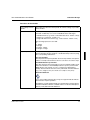
4.2.4 Type of Collating Marks (on the ’Mark’ tab) - Manual
Select manual or automatic (see chapter "Type of Collating Marks (on the ’Mark’ tab) - Automatic" on page 53). Manual generation allows you to select a stored IOCA mark and to
position it. You have to specify all parameters like position, extent and offset of the mark.
Figure 33
A29247-X21-X-6-7670
Window 'Signature' – 'Marks' -> Manual Generation
51
Signatures
The Impose Menu and Section
4.2.4.1 Selection
’On physical page’
Indicate on which physical page the gathering mark must be printed.
The following expressions are valid:
n
n - integer
n / integer
n / integer - integer
n / integer + integer
’Selection’
To select the IOCA mark, click 'File Selection' (which opens a File
Selection Box) or enter the fully qualified file name in the 'Selection'
text field. Marks must have been previously created and saved with
the Print Job Manager as resources in the $COMPOSER directory.
4.2.4.2 Extent (Width/Hight)
This area defines the size of the marks in width and hight. The mark is trimmed to correspond to the specified values relative to the origin (left upper corner).
4.2.4.3 Position’ (X/Y)
The position, relative to the image origin, where the marks must be printed.
4.2.4.4 Offset (X/Y)
Here you determine the offset between one mark and the next, when the gathering mark
must be printed with some degree of offset in each successive section.
4.2.4.5 Units
Select mm, cm, inch or pel for the x and y direction.
52
A29247-X21-X-6-7670
The Impose Menu and Section
Signatures
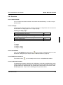
4.2.5 Type of Collating Marks (on the ’Mark’ tab) - Automatic
Automatic generation calculates the signature marks. Here the physical page pointing outward is automatically found and the mark is positioned in the middle between the folding of
logical pages. The default mark is s mm wide and 1 cm long. If the mark sequence does not
work out that way, the marks are shortened accordingly.
4.2.5.1 Folding type
Standard
The mark is positioned in the middle between the folding of logical pages. The position of
the mark of the first signature depends on the rotation of the logical pages, because the first
mark is always positioned 1 cm from the edge of the logical page.
The default mark is 2 mm wide and 1 cm long. If the mark sequence does not work out that
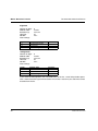
way, because of a big number of signatures and a short folding edge, the marks are repositioned again from the origin:
Repositioning of the mark
Figure 34
Repositioning the mark from the origin
Figure 35
Positioning of signature marks
A29247-X21-X-6-7670
53
Signatures
The Impose Menu and Section
Example: Signature marks two up
Figure 36
Mark within the first signature with different rotation of logical pages
If folding is not possible due to the chosen impositioning, the composer will give an error, if
automatic marks are selected.
54
A29247-X21-X-6-7670
The Impose Menu and Section
Signatures
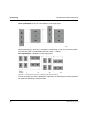
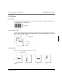
Example: Positioning of a four up mark
The arrow shows the starting position of the first mark and the direction of the following
marks. The star points out the last mark of the sequence.
Figure 37
Mark positioning at 0° rotation
Figure 38
Mark positioning at 180 rotation
Figure 39
Mark positioning at 90° rotation
Figure 40
Mark positioning at 270° rotation
A29247-X21-X-6-7670
55
Signatures
The Impose Menu and Section
Example: Mark positioning with "Two Up & Identical copies"
Figure 41
Positioning of marks with "Two Up & Identical copies"
Caution:
The mark will be positioned for all copies exactly between the 2 "Two Up"
pages without considering user defined shifts (see Positioning).
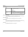
High Folio/Low Folio
Sheets are often not folded symmetrically during postprocessing, resulting in high or low
folios. Therefore the gathering mark must not be placed symmetrically on the sheet but has
to be shifted according to the width of the folio:
1
n
Symmetrical
Folio
n
Low Folio
1
n
1
High Folio
Insert the width of the high or low folio in the ’Extent’ field.
56
A29247-X21-X-6-7670
The Assemble Menu and Section
5 The Assemble Menu and Section
All functions in this menu refer to the physical pages of the document after the impositioning. Here you can for instance modify the page layout by changing the position of the logical
pages (images), by inserting blank pages or by positioning marks on the sheets.
A29247-X21-X-6-7670
57
Positioning
The Assemble Menu and Section
5.1 Positioning
Depending on which impositioning mode has been selected under 'Impositioning' the logical pages initially are automatically assigned a default positioning that is appropriately
matched to the impositioning mode.
Figure 42
Window ’Positioning’
The following diagrams illustrate object positioning with the different impositioning methods:
58
A29247-X21-X-6-7670
The Assemble Menu and Section
Positioning
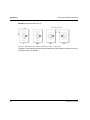
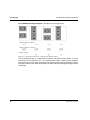
One up-Example: A5 object on A3 target paper
Figure 43
Positioning of an A5 object on A3 paper with different rotations
In 'One up' impositioning mode, the image is rotated about the front edge of the sheet if so
specified, and then moved to the physical origin of the page (left upper corner).
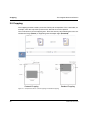
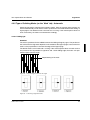
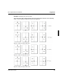
Two up-Example: 2 A5 objects on A3 target paper
Figure 44
Positioning of 2 A5 object on A3 paper with different rotations
In 'Two up' mode, the sheet is halved parallel to the X edge of the sheet and the objects
rotated within their respective half of the page.
A29247-X21-X-6-7670
59
Positioning
The Assemble Menu and Section
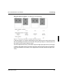
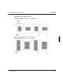
Three up-Example: 3 29.7cm*14cm objects on A3 target paper
Figure 45
Positioning of three29.7cm × 14.0cm objects on A3 paper with different rotations
Object positioning in 'Three up' is analogous to positioning in 'Two up', but with the difference that the sheet is now divided into thirds (1 third = 1 object).
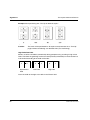
Four up-Example: 4 A6 objects on A3 target paper
Figure 46
Positioning of 4 A5 objects on A3 paper with different rotations
In 'Four up' mode, the sheet is divided into 4 quadrants and the objects are then placed on
the quadrants following a clockwise order.
60
A29247-X21-X-6-7670
The Assemble Menu and Section
Positioning
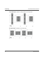
Identical Copies- Example: 2 A5 objects on A3 target paper
Figure 47
Positioning of 2 A5 objects on A3 paper with various rotations
In 'Identical copies', the number and positioning of the objects on the sheet is derived from
the corresponding parameters for the number and spacing of objects as defined under "Define objects on the page for Identical Copy".
The entire object field is always moved to the physical origin (left upper corner) of the page.
In duplex and tumble printing, the objects placed on the back of the sheet are aligned exactly with the objects on the front (i.e. the registration of the front and back images is the
same).
A29247-X21-X-6-7670
61
Positioning
The Assemble Menu and Section
Two up&Identical Copy-Example: 2 A6 objects on A3 target paper
Figure 48
Positioning of 2 A6 objects on A3 paper with different rotations
'Two up & Identical copy' is a combination of 'Two up' and 'Identical copy' modes, i.e. it contains all the 'Two up' schemes, but – as in 'Identical Copy' mode – objects can be copied on
a physical page as many times as desired. The number and spacing are defined as in 'Identical Copy'. Here too, the entire object field is moved to the physical origin (left upper corner)
of the page.
62
A29247-X21-X-6-7670
The Assemble Menu and Section
Positioning
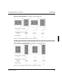
Positioning when 'Center' is active
One up-Example: 1 A5 object on A3 target paper
Figure 49
Positioning with "One Up" and 'centred print'
Two Up-Example: 2 A5 objects on A3 paper
Figure 50
A29247-X21-X-6-7670
Positioning with "Two Up" and 'centred print'
63
Positioning
The Assemble Menu and Section
Three Up-Example: 3 (10.5cm ¥ 20.0cm)-Objects on A3 target paper
Figure 51
Positioning at "Three Up" with 'centred print'
Four Up-Example: 4 A6 objects on A3 target paper
Figure 52
64
Positioning at "Four Up" with 'centred print'
A29247-X21-X-6-7670
The Assemble Menu and Section
Positioning
Identical Copies-Example: 2 A5 objects on A3 target paper
Figure 53
Positioning with "Identical copies" and 'centred print'
In duplex and tumble mode, the objects placed on the back of the sheet are aligned exactly
with the objects on the front (i.e. the registration of the front and back images is the same).
Two up&Identical Copy-Example: 2 A6 objects on A3 target paper
Figure 54
A29247-X21-X-6-7670
Positioning with "Two Up & Identical copies" and 'centred print'
65
Positioning
The Assemble Menu and Section
If you start out with the default positioning variants described above (Options -> Center/
Standard) you can additionally shift the images in the X- and Y-directions. Generally such
a move is not required to achieve exact registration of front and back images, if the actual
target paper size is the same as the paper size selected during impositioning, and if the
printer generates no differences in printing the front and back sides.
You always need to move the object when the printer setting generates a shift, or when the
actual paper size doesn’t match with the paper size defined during impositioning.
You can shift each object (with the exception of Identical Copy or Two up & Identical
Copies objects) in the X- and Y-directions independently of all other images.
In Identical Copy or Two up & Identical copies you can only move the entire object field
as a whole on a physical page.
Click Apply to confirm all settings in the 'List of image positions' and return to the Composer
main window; or click Discard to disregard all changes and return to the Composer main
window.
5.1.1 Options
66
’Center’
If you activate the option, the images are arranged centred to the physical page
and their position does not relate to the origin of the physical page.
’Standard’
The orientation of the image relates to the origin of the physical page in the upper
left corner in portrait mode.
A29247-X21-X-6-7670
The Assemble Menu and Section
Positioning
5.1.2 Position
’Sheets’
Here you select the physical pages where you need to give images additional shift values.
You can choose among different ways of defining the pages:
-
Specifying the page range (e.g., page 1 to last page - Pattern: 1-n)
Specifying individual pages (e.g., page 1, page 5, page 19, secondlast page - Pattern: 1,5,19,n-1)
Specifying the page range and an interval. For example, you have
defined the range from page 1 to page 20, but image positions must
be corrected on every second physical page (Pattern: 1-20:2 - page
1 to page 20, colon identifies the interval).
The following expressions are valid:
n
n - integer
n / integer
n / integer - integer
n / integer + integer
’Position on X / Y’
The values in these fields determine the distance on the x and y axis – measured in mm, cm, pel or inch – by which the image must be moved.
5.1.3 Side
’Front’
By selecting 'Front' (front side) in tumble or duplex layout, you can set separate shifts for
the front sides.
Example:
Shift corrections must be made on all front sides. Pages: 1-n Side: front
’Back’
By selecting 'Back' (back side) in tumble or duplex layout, you can set separate shifts for
the back sides.
Example:
Shifts must be added on every second back side of the entire print file (pages 1, 3, 5, 7,
...) Pages: 1-n:2 Side: back
A29247-X21-X-6-7670
67
Positioning
The Assemble Menu and Section
5.1.4 Image sequence
’Define your
sequence’
Once you have used ‘Side’ and ‘Sheets’ to determine the physical page
of the image that requires a shift, you must select the image itself by entering the image number.
Figure 55
Image numbering for different impositioning schemes
Examples:
The input file is impositioned Two up. The bottom image (image 2) must be shifted
on the last front side:
Sheets: n Side: Front image: 2
The right bottom image (image 3) must be shifted on all back sides in a Four up
file: Sheets: 1-n Side: Back image: 3
5.1.5 List of settings
To have the shift settings accepted, you must transfer them to the 'List of image positions'
(see chapter "List of settings" on page 8). Then click Apply to finally accept the settings.
68
A29247-X21-X-6-7670
The Assemble Menu and Section
Blank Sheets
5.2 Blank Sheets
In certain applications (e.g., blank sheets between the cover and inside sheets of a book or
booklet, or divider sheets in a cut-sheet publication), you might want to insert blank sheets
into an existing print file. With cut sheet printers that have several paper input trays, you can
use the Composer to control the paper feed so that the paper for these blank sheets is
drawn from a different tray. This enables you to use heavier-weight stock or even pre-printed paper.
Figure 56
Note:
Window ’Blank Sheets’
The insertion of blank sheets increases the total number of printed pages of
the print file. Functions performed afterwards, such as 'Input Trays' and
'Marks', will then work with the ”new” print file with the larger number of physical pages.
Example: A blank sheet is inserted before sheet 1. This increases the number of physical
pages by 1:
Figure 57
A29247-X21-X-6-7670
Blank Sheets - Insert a blank sheet before page 1
69
Blank Sheets
The Assemble Menu and Section
Use the 'Input trays' function to withdraw the second sheet from Tray C:
Figure 58
In and output trays - Inputtray C for the second sheet
5.2.1 Options
’Number’
Defines the number of paper sheets to be inserted into the already impositioned document.
’Before’ / ’After’
Blank sheets can be inserted ('before') or ('after') a specified sheet.
’Sheet Number’
This function allows the exact selection of the sheet before or after which the
blank sheets are to be inserted. You can choose among these selections:
Absolute specification of the paper sheet (e.g., before sheet 14 - Pattern: before 14)
Relative specification of the second-last paper sheet (e.g., after the secondlast sheet –Pattern: after n-1)
The following expressions are valid:
n
n - integer
n / integer
n / integer - integer
n / integer + integer
n + 1 (with insert ’After’)
5.2.2 List of settings
To confirm these settings, you must enter them in the 'List of selected blank pages' (see
chapter "List of settings" on page 8). Then click Apply to finally accept the settings.
70
A29247-X21-X-6-7670
The Assemble Menu and Section
Job offset & trays
5.3 Job offset & trays
' This function is useful only with cut sheet printers. By selecting different paper feed trays
or output trays you can integrate different paper weights, different paper colors or pre-printed sheets into the print material or you can output certain sheets separately.
Note:
If the PDC is called via the PJM, the input and output trays of the currently
selected printer are presented in this window.
If you start the PDC as standalone application, only the trays of an default
printer are shown.
The paper input can be controlled either directly by the selection of tray numbers or by the
selection of media names (only with printers capable of media names).
Printers supporting media names can therefore be controlled independently from the physical trays by the selection of the description of the paper types you want to use for printing.
In addition to specifying the trays, you can also assign a job offset (cut sheet printer) or
EOT marks (fanfold printer) to the paper sheets.
Figure 59
A29247-X21-X-6-7670
Window ’Job offset and trays
71
Job offset & trays
The Assemble Menu and Section
Note:
If no settings are performed under Job offset & trays, then the existing Tray
and Job Offset parameters of the input files are retained. If, however, a tray
and Job offset setting is defined for at least one sheet, all sheets not specifically listed in the 'List of Settings' are assigned the entry "Tray A without job
offset".
Example:
The 'List of selected trays and job offsets' contains the following entries:
Sheets
Input tray
Output tray
Job offset
1
A4pink
C
no
n
2
B
yes
The paper sheets 2 through the second-last sheet n-1 are not on the list and will therefore
be taken by default from tray 1 without job offset.
Any list entries that relate to the same sheet numbers overwrite each other. The last entry
overwrites the first.
Example:
Sheets
Input tray
Output tray
Job offset
1-n
1
A
No
n
2
B
Yes
Sheets 1 through n-1 are taken from tray 1 without job offset, the last sheet from tray 2 with
job offset.
Click Apply to confirm all settings and return to the Composer main window; or click Discard to disregard all changes and return to the Composer main window.
72
A29247-X21-X-6-7670
The Assemble Menu and Section
Job offset & trays
Functions of the window
’Use settings form input file’
The setting are taken from the input file. No further settings are possible
in this window.
’Sheets’
In this input field you specify sheets for which a specific input tray is to be
selected. A valid entry can consist of individual sheets and ranges.
- Individual sheets (e.g., sheets 1, 20 and the last sheet - Pattern: 1,20,n)
- Ranges (e.g., all sheets - Pattern: 1-n)
- Range with interval increments (e.g., each 3rd sheet - Pattern 1-n:3)
The following expressions are valid:
n
n - integer
n / integer
n / integer - integer
n / integer + integer
’Input tray/media’
Here you select the paper feed tray or the preferred print media. You define the desired mode (tray numbers or media based tray selection) using
the corresponding radio buttons.
Use Tray numbers
The drop down list ’Input tray/media’ shows the tray number of the printer
which is currently selected in the PJM. You can select one of these trays.
Use Media based Tray selection
The drop down list ’Input tray/media’ now shows all printer medias available in the database of the PRISMAproduction system. (see the PRISMAproduction user manual on how to configure user defined print
media). The list indicates the name of the print media. All other attributes
(e.g. color, weight or size) are shown as a tooltip for every entry.
Read from database
If you open a PDC parameter file (*.imp), the original media list will also
be restored for ’Input tray/media’.
Reading the currently defined media from the database using the button
’Read from database’ deletes outdated entries from the list and replaces
them by newly defined media definitions.
A29247-X21-X-6-7670
73
Job offset & trays
’Output tray’
The Assemble Menu and Section
Output tray
Here the output tray is selected (cut sheet printers). The presented trays
depend on the printer which is currently selected in the PJM.
Job Offset
The default setting no deactivates the job offset, while the setting yes inserts a job offset command before the sheets selected in the ‘sheets’ text
field. This command is then transmitted via the interface to the post-processing device, where it is used as a ‘binding’ command.
5.3.1 List of settings
To confirm these settings, you must enter them in the 'List of selected blank pages' (see
chapter "List of settings" on page 8). Then click Apply to finally accept the settings.
74
A29247-X21-X-6-7670
The Assemble Menu and Section
Creep
5.4 Creep
Figure 60
Window 'Creep'
This option is only relevant if the printing area for folded and interleaved sheets must be
corrected to offset the paper thickness and make sure all sheets in the booklet retain the
same external margin after trimming.
The 'Creep‘ function is available only in combination with the following impositioning types:
•
Two up
•
Two up & Identical copies
•
Four up
All other Composer impositioning modes are unsuited for generating folded booklets or
books, and can therefore not be combined with 'Creep'.
A29247-X21-X-6-7670
75
Creep
The Assemble Menu and Section
5.4.1 Original image position
5.4.1.1 Standard Folding
Standard folding must be activated for booklets with a single fold (or for book sections),
i.e. when the sheets are cut first, then interleaved, and finally are all folded as a unit
around one edge (see diagram below).
Figure 61
76
Positioning of the pages with creeping in the production of a folded booklet
A29247-X21-X-6-7670
The Assemble Menu and Section
Creep
If you select inside, the images located on the inner sheet after folding are assigned their
original positioning:
Figure 62
A29247-X21-X-6-7670
Creep with Standard folding 'inside'
77
Creep
The Assemble Menu and Section
If you select outside, the images on the outermost sheet of the folded booklet occupy their
original positions (i.e. before 'Creep' was activated):
Figure 63
Creep with Standard folding 'outside'
5.4.1.2 Signature Folding
You can only activate 'Signature folding' in conjunction with Four up and Signatures. When
printing signatures, you must usually make corrections to the printing area in two directions.
78
A29247-X21-X-6-7670
The Assemble Menu and Section
Creep
Example:Signature with 32 pages:
Figure 64
Folding of a signature sheet
The last two folds are the ones that determine the printing area correction, as they involve
the folding of a stack of individual sheets around an axis. You perform the printing area
correction for the last fold by activating 'Standard folding'. For the printing area correction
with the second-last fold (Fold 4) you additionally need to select 'Signature folding'.
Figure 65
A29247-X21-X-6-7670
Example for page positioning with 'Signature folding'
79
Creep
The Assemble Menu and Section
5.4.2 Paper settings
5.4.2.1 Paper weight (g)
The paper thickness determines the extent of the printing area correction. You must therefore be sure to specify the paper weight (in grams). The larger the value you enter, the larger will be the correcting shift from one sheet to the next.
5.4.2.2 Volume
Additionally to the weight the paper volume is considered for the creeping. The default setting is 1, with rising values the creeping increases.
80
A29247-X21-X-6-7670
The Assemble Menu and Section
Marks
5.5 Marks
Apart from the signature marks, you can also define and position marks, which relate to the
physical pages (i.e. cut marks, page numbering, etc). Like the overlays, which relate to
logical pages, single page marks (select the Marks tab) or multipage mapping files (select
the File mapping tab) can be processed. In contrast to Overlays (Integrate section), the
Marks (Assemble section) are positioned on the physical pages.
A possible application would be to create a consecutive numbering of the print sheets.
Figure 66
A29247-X21-X-6-7670
Window ’Marks’ - Marks on a single page
81
Marks
The Assemble Menu and Section
Figure 67
82
Window ’Maeks’ - ’Filemapping’
A29247-X21-X-6-7670
The Assemble Menu and Section
Figure 68
A29247-X21-X-6-7670
Marks
Inserting marks in the print file
83
Marks
The Assemble Menu and Section
5.5.1 Define marks
’On physical pages’
Specify the physical page(s) on which you want to print the marks.
Examples:
On single sheets:
on the first and last sheet: 1,n
on the sheet before the last: n-1
On sheets within a range:
not on the last 60 sheets: 1-n-60
on every second sheet, i. e., in duplex or tumble printing on all front
sides: 1-n:2
The following expressions are valid:
n
n – integer
n / integer
n / integer - integer
n / integer + integer
’Selection’
To select the mark in IOCA format, either click the folder button or enter
the fully qualified file name in the 'Selection' text field. Marks can only be
selected in the Composer, if they have been created before and have
been stored as a resource in the $COMPOSER directory in the Print Job
Manager (Suffix .mrk for single and .map for multiple page files).
’Extent’ (Width/Hight)
Values for width and hight determine the absolute size of the mark.
’Position’ (X/Y)
Once the mark has been created in this way, it can be placed in any desired position on the physical page. You specify the position of the mark’s
origin in terms of the X- and Y-coordinates.
’Offset’ (X/Y)
Here you specify the offset from one mark to the next. Offset specifications are effective only if you have specified a range of target pages (with
interval increments if applicable).
Examples:
On physical pages: 1-n:10 Offset X = 0 cm; Y = 0.5 cm
The mark appears on every tenth page, always with a 0.5 cm offset in the
Y-direction.
On physical pages: 1-20 Offset X = -3 mm; Y = 1 mm
The mark appears on each page between 1 and 20, offset by -3 mm in
the X-direction and by 1mm in the Y-direction.
’Units’ (X/Y)
84
Set the units for the X and Y direction. You can select mm, cm, pel or
inch.
A29247-X21-X-6-7670
The Assemble Menu and Section
Marks
5.5.2 Define the file mappings
’Selection’
To select the mark in IOCA format, either click the folder button or enter
the fully qualified file name in the 'Selection' text field. Marks can only be
selected in the Composer, if they have been created before and have
been stored as a resource in the $COMPOSER directory in the Print Job
Manager (Suffix .mrk for single and .map for multiple page files).
’Pages’
If you want to specify a part of the mapping file, select a range here.
The following expressions are valid:
n
n – integer
n / integer
n / integer - integer
n / integer + integer
’Target Page’
Using multiple page mapping files you may select a sheet to start your
mapping from. Additionally the selection of a step width is possible:
-
on physical page 8: 8
in the middle of the print file: n/2
starting from the fourth last on every second page: n-4:2
The following expressions are valid:
n
n – integer
n / integer
n / integer - integer
n / integer + integer
5.5.3 List of settings
To confirm these settings, you must enter them in the 'List of selected blank pages' (see
chapter "List of settings" on page 8). Then click Apply to finally accept the settings.
A29247-X21-X-6-7670
85
Marks: Barcode-Function
The Assemble Menu and Section
5.6 Marks: Barcode-Function
In the Marks dialog you are also able to define barcodes and to position them on any sheet
in the print file.
Figure 69
The barcode tab in the ’Marks’ dialog
Today you find barcodes in nearly all industrial, commercial and medical fields. Depending
on the requirements different codes are being used. Within the PDC you can now use the
following Codes:
86
•
EAN-8
•
Code 39
•
Interleaved 2-of-5
•
Data Matrix (Océ)
A29247-X21-X-6-7670
The Assemble Menu and Section
Marks: Barcode-Function
’EAN-8’
Formerly ’European Article Number’, today trademark of the Identification and Barcode
System administered by the International Article Numbering Association (EAN). EAN is a
wordwide standard allowing to perform unique identifications. With this number articles, logistic units and adresses of partner can be labelled uniquly.
The EAN-8 barcode is 8 characters long and contains only numerals - no letters and other
characters are accepted. 7 characters are reserved for the data, the last is a control digit,
which results from a testcalculation over the contents of the barcode. This control digit is
used by the barcode scanner to verify that the correct barcode is used.
Example of an EAN-8 barcode (Data: ’0123456’, automatically generated control digit: ’5’):
’Code 39’
Code 39 is a alphanumeric barcode, which represents digits from 0 to 9, 26 capital letters
(A-Z) and 6 special characters (-.$/+% and blancs). Up to 50 characters can be displayed.
Every character consists of 9 elements (5 bars and 4 gaps), 3 of them wide and 6 narrow.
Code 39 has no additinal control digit.
Code 39 example representing the word ’CODE 39’:
’Interleaved 2-of-5’
Interleaved 2-of-5 is a numeric barcode, where the coded data must consist of an even
number of digits. Up to 50 characters can be displayed.
’Interleaved’ means that one digit is coded in the bars of the barcode and the successing
digit is coded in the gaps of the barcode. Therefore the coded digits interleave. Each digit
consists of 5 elements (5 bars or 5 gaps), 2 of them wide and 3 narrow.
A29247-X21-X-6-7670
87
Marks: Barcode-Function
The Assemble Menu and Section
’Data Matrix (Océ)’
Barcodes like EAN 8 , Code 39 and Interleaved 2-of-5 are linear codes. Because of the linear orientation, barcodes are very much limited in respect of the length of information. Furthermore, the linear orientation has to be considered when scanning the barcode. The code
therefore cannot be read in any position.
The Data Matrix Code codes the data horizontally and vertically. Therefore the position of
the code is not important for reading. The matrix structure also allows to represent much
more data.
Data Matrix Code example
88
A29247-X21-X-6-7670
The Assemble Menu and Section
Marks: Barcode-Function
5.6.1 Selection
5.6.1.1 Select Barcode
You can select all barcodes created in the window ’Barcode Settings’ as well as the predefined codes.
5.6.1.2 On Pages
In this field you define the pages on which the barcode is to be printed. You can insert the
barcode either on single pages or on a range of pages.
Inserting on single pages:
on pages 1 and n:
on the page before the last page:
1, n
n-1
Inserting on multiple pages within a range:
on the entire file - except the last two pages:
on every second page:
1-n-2
1-n:2
The following expressions are valid:
n
n - integer
n / integer
n / integer - integer
n / integer + integer
5.6.1.3 User defined
If you set user defined and click the icon:
, you can enter all required values for a new
barcode in a dialog box (see chapter "Define/Modify Barcode" on page 93).
5.6.1.4 Modify the barcode list
If you click the icon
, you can modify the list of user- and predefined barcodes.
5.6.1.5 Predefined Barcodes
The predesigned barcodes ’digistich’ and ’revDigistitch’ are already installed on the system.
These barcodes correspond to position and hight settings of the barcodes ’Barcode1.mrk’
and ’Barcode2.mrk’ distributed with the special release of the PDC V2.10.15 for the IBIS
DS2000 application. They have the following preset parameter values:
A29247-X21-X-6-7670
89
Marks: Barcode-Function
The Assemble Menu and Section
digistitch
Number of digits
Module width
Barcode Typ
HRI Text
WE:NE:
Field settings:
Fields
1-2
3-4
5-8
8
13 mils
2 of 5 Int
no
2.5:1
Content Type
Actual Sheet number
Total sheets
constant string
Contents
0000
revDigistitch
Number of digits
Module width
Barcode Typ
HRI Text
WE:NE:
Field settings:
Fields
1-2
3-4
5-8
8
13 mils
2 of 5 Int
no
2.5:1
Content Type
Sheet number reverse
Total sheets
constant string
Contents
0000
If you move the mousepointer over a barcode entry in the list, a small help window opens
with a short info on the type of the barcode. This makes it easier for you select the correct
barcode from the list.
90
A29247-X21-X-6-7670
The Assemble Menu and Section
Marks: Barcode-Function
5.6.2 Settings
5.6.2.1 Hight
In this field you define the hight of the barcode Value from 6mm to 100mm are allowed. You
can select ’mm’, ’cm’, ’pel’ or ’inch’.
5.6.2.2 Position on X/Y
You can place the barcode on any position of the physical page. To do this you define the
position of the barcode origin (the left upper corner) via the X and Y coordinates. You can
choose ’mm’, ’cm’, ’pel’ or ’inch’.
5.6.2.3 Rotation
Choose from the list either 0°, 90°, 180° or 270°.
A29247-X21-X-6-7670
91
Marks: Barcode-Function
The Assemble Menu and Section
5.6.3 Automatic Positioning
Apart from the possibility to define the position and hight of the barcode by yourself, you
can also choose between two automatic settings ’Digistich1’ and ’Digistich2’. The default
entry in the listbox is ’No’.
Only if you choose ’No’, you can make your settings, otherwise the fields in the ’Settings’
section are greyed out. Dependend on the target papersize the settings are calculated automatically.
The predefined barcodes correspond to position and hight settings of the barcodes
’Barcode1.mrk’ and ’Barcode2.mrk’ distributed with the special release of the PDC
V2.10.15 for the IBIS DS2000 application.
Barcode positioning for ’Digistich1’:
Barcode positioning for ’Digistich2’:
92
A29247-X21-X-6-7670
The Assemble Menu and Section
Marks: Barcode-Function
5.6.4 Define/Modify Barcode
Click this button, if you have selected ’user defined’ in the field Select barcode, to open a
window, which allows you to set all parameters for a user defined barcode and add it to the
barcode list. If you have selected an already defined barcode, the same window opens to
show the related settings. In this case you can modify the settings.
Figure 70
Window ’Define barcode’
5.6.4.1 Barcode Settings
Barcode Name
Before clicking ’OK’ and returning to the main window, you have to assign a name to the
new barcode in this edit field.
Barcode type
Select one of the three following barcode types:
•
EAN 8
A29247-X21-X-6-7670
93
Marks: Barcode-Function
•
Code 39
•
Interleaved 2-of-5
•
Data Matrix (Océ)
The Assemble Menu and Section
Number of fields
In this field enter the number of internal fields within the barcode. E.g. if you want to code
the string ’test-123’ as a barcode, it must be 8 fields long. The maximum number of fields
depends on the barcode type:
Barcode type
Valid number of fields
Code 39
50 characters
EAN-8
Exactly 7 characters
This barcode consists of 7 digits (data) and 1 automatically generated control digit (=digit 8)
Interleaved 2-of-5
50 characters
Data Matrix (Océ)
2000 characters
Module width
With the module width you can define the width of the most narrow barcode element. Barcode elements are represented either as bars within the barcode or gaps between the bars.
The module width can be indicated as mils, mm, pel or inch, whereas 1 inch equals 1000
mils.
Valid values for Code 39 and Interleaved 2-of-5 are between 7 mils and 100 mils. For EAN
between 9 mils and 26 mils.
With Data Matrix (Océ) the valid range of values is between 6 mils and 254 mils.
If you do not give a value, the default settings of the printer will be used.
Wide-to-narrow (WE:NE)
This value defines the ratio of a wide barcode element to a narrow element for barcodes,
which only contain elements of two different sizes (= two level barcodes). These are the
barcode types Code 39 and Interleaved 2-of-5, not EAN-8.
The valid range of values is between (2:1) - (3:1), e.g. 2.25:1.
If you do not give a value, the default settings of the printer will be used.
94
A29247-X21-X-6-7670
The Assemble Menu and Section
Marks: Barcode-Function
Example: WE:NE = 2.00:1
Barcode length
Clicking this button calculates the length of the barcode dependent on the number of fields,
the module width and the WE:NE ratio. The value is then inserted in the barcode length
field. The calculated length refers to the left margin of the first bar to the right margin of the
right bar.
HRI text
HRI means ’Human Readable Interpretation’. If you activate the box, the contents of the
barcode will additionally be printed as a readable string (latin characters and arabic digits).
Deactivated is the default setting.
HRI text is not available for Data Matrix (Océ).
5.6.4.2 Field settings
You can now divide the number defined in the ’Number of fields’ field into groups, which can
be filled with different contents.
Example:
The barcode should have 8 fields. The first two fields should each contain the actual sheet
number, on which the barcode is to be printed. Fields 3-4 shoud contain the total number
of sheets in the print file and the last 4 fields should represent the constant number ’4711’.
To do this, you have to insert the following values into the text fields Field range, Content
and Content typ:
Field range
Content type
1-2
Actual sheet number
3-4
Total number of sheets
5-8
Constant String
A29247-X21-X-6-7670
Content
4711
95
Marks: Barcode-Function
The Assemble Menu and Section
These values have to be transferred into the ’List of settings’, otherwise the data will be lost.
To modify this list, use the icons on the top of this list.
Field range
You have different possibilities to divide the barcode fields into groups:
•
Indicate a range (e.g. field 1 to 2: 1-2)
•
Indicate a single field (e.g. field 7: 7)
Data type
This selection field forms together with the Field content the contents of the barcode fields.
You can select one of the following content types:
96
•
Constant string: allows you to insert a constant string in the text field ’Content’.
•
Variable string: allows you to define via the text field ’Content’ variable fields (e.g.
counter) in the barcode
•
Actual sheet nr: Contains the number of the actual sheet, on which the barcode is
printed. No entry in the text field ’Content’ is possible.
•
Total number of sheets: Contains the total number of sheets to be printed. No entry
in the text field ’Content’ is possible.
•
Sheet number reverse: Contains a counter, which counts back beginning with the last
(highest) number of sheets in the print file. No entry in the text field ’Content’ is possible.
A29247-X21-X-6-7670
The Assemble Menu and Section
Marks: Barcode-Function
Field contents
Dependend on the Data type you have chosen, you can insert the following into this text
field:
’Data type’
Contents
’Constant string’
The valid characters depend on the selected barcode type:
–
–
–
–
–
–
’Variable string’
EAN-8 and Interleaved 2-of-5:
0123456789
Code 39:
0123456789ABCDEFGHIJKLMNOPQRSTUVWXYZ
-.$/+% and blanks
Data Matrix (Océ):
EBCDIC-Code:
0123456789 ABCDEFGHIJKLMNOPQRSTUVWXYZ
bcdefghijklmnopqrstuvwxyz
/!:.$,#<*%@()+;>=|?\&- and blanks
Definition of a variable counter.
Example 1: A barcode is to be printed on each page of a 100 pages
file. Within the barcode it should be counted from 1 to 100. The following has to be inserted into the field:
1:1 (starting number:counter steps)
The following expressions are valid:
integer:integer
Integer:-integer (count backwards)
n:-integer (count backwards beginning from the last sheet number)
Example 2: Field range: 1-2, Content: 1:1 => It is counted from 01,
02, ... to 99. If there are more barcodes to be printed, the next starts
again with 01.
In case of a counter overflow the counter will be reset to the start value and the counting starts again.
’Actual sheet number’
No entries possible
’Total number of sheets’
No entries possible
’Sheet number reverse’
No entries possible
After you have done all necessary entries and after you have transferred the field settings
into the List of settings, click ’OK’ to store the newly defined barcode and to return to the
previous window. The new barcode will now appear in the barcode selection list as the first
entry. If you choose ’Cancel’ nothing will be stored and you return to the previous window.
A29247-X21-X-6-7670
97
Marks: Barcode-Function
The Assemble Menu and Section
5.6.5 Modify the barcode list
Window ’Marks’ - ’Barcode’ - ’Modify the barcode list’
The list of barcodes is not static and can be modified at will. I.e. you can add or delete entries, modify names and tooltip comments.
A click on the icon ’Modify scheme list’ opens the window above.
The actual list of barcode with barcode name, type and number of fields ist displayed.
Rename a barcode
Mark the entry of the barcode you want to rename by clicking on it. The actual name is displayed in the ’Selection’ field. Type in the new name in the ’New name’ field and click ’Rename current barcode’:
98
A29247-X21-X-6-7670
The Assemble Menu and Section
Marks: Barcode-Function
Delete selected List Item
To delete one or more elements from the list, mark the entries and click the Icon ’Delete
current barcode’:
Caution:
Deleted barcodes cannot be restored!
Move selected List Item up/down
Use these buttons to move a selcted item or a group of items one step up or down. This
allows you to organize the order of the list at will.
Restore the current default barcodes
Clicking this icon restores the list before the last modification.
Accept the Comment for this Scheme
If you move the cursor over an element in the list of barcodes in the barcode window, a
small help window pops up displaying information o the barcode, the number of fields and
a freeform comment (e.g. on the contents of the barcode). You can edit this comment in the
text field in the ’Modify scheme list’ window. Clicking the icon above links the comment to
the selected barcode.
Copy the current barcode
You can also copy any barcode by editing a new name in the field ’Copy barcode to’ and
clicking the above icon. The newly generated barcode has identical properties (type, number of fields, contents, etc.), only it’s name is different.
A29247-X21-X-6-7670
99
Marks: Barcode-Function
The Assemble Menu and Section
5.6.6 Rebuilding the Barcode Applications Barcode1.mrk and Barcode2.mrk
Both applications come from the special release of the PDC V2.10.15 for the IBIS DS2000
Digistich application.
Barcode1.mrk
1. Select the predifined barcode ’Digistich’ from the list.
’Digistich’ has the following preset parameter values:
Number of fields:
Module widzh:
Barcode type:
HRI Text:
WE:NE:
Content:
8
13 mils
2 of 5 Int
no
2.5:1
From/to
Content type
1-2
Actual sheet number
3-4
Total number of sheets
5-8
Contant String
Content
0000
2. If you want to modify the default squence ’0000’ for the fields 5-8, open the window ’Barcode Settings’ to change this value. Close this window by clicking ’OK’. The modification will be applied to the barcode ’Digistich’
3. In the text field ’Pages’ insert the sequence ’2-n:2’ to ensure, that the barcode will always be printed on the back of each sheet.
4. Select ’Digistich1’ in the field ’Automatic Positioning’.
5. Insert these settings in the ’List of settings’ (’Add the new item’) and close the window
with ’OK’.
Barcode2.mrk
Proceed as described for barcode2.mrk. Select ’Digistich2’ instead of ’Digistich1’ from the
list ’Automatic Positioning’.
100
A29247-X21-X-6-7670
The Assemble Menu and Section
Print Range
5.7 Print Range
This parameter enables you to set the page limits of the output file. Only pages within these
limits are placed in the output file. 'Print range' accesses the already impositioned file.
Figure 71
A29247-X21-X-6-7670
Window ’Print Range’
101
Print Range
The Assemble Menu and Section
Example:
Print range: from 4 to 10: 3 sheets are printed:
Figure 72
Notes:
Printed sheets at example selection 'print range' (from 4 to 10)
Specify the logical page numbers in the fields 'From' and 'To'. If one such
page is located on the back of a sheet, the file is printed with the front page
that goes with it. Complete sheets (front and back side) are always generated.
If you combine variable data with print range, the PDC generates one output file with all issues (over all variable data sets).
102
A29247-X21-X-6-7670
The Assemble Menu and Section
Print Range
Example:
Input file:
Output file:
10 pages, 'Variable Data' file: 2 pages
2 × 10 pages = 20 pages
These 20 pages are impositioned for example as a "One Up, scheme 2" (n,-1,0: reversed
sequence, last to first page):
Figure 73
Print file before and after Impositioning "One Up, scheme 2": (n,-1,0), Duplex
Range values relate now the logical pages after integration (here the logical pages 1-20).
Figure 74
Printed sheets at a range from 7 to 10
Figure 75
Printed sheets at a range 7 to 11
A29247-X21-X-6-7670
103
Print Range
The Assemble Menu and Section
Functions of this window
’Print Range’
You can choose among the following functions:
- 'All' (default setting) - prints the entire document
- 'Range' – lets you define the print range.
’From page (image) number’
Start of the print range (this window is only activated after the
‘Range’ function has been selected in the 'Print' window).
’To page (image) number’
End of the print range (this window is only activated after the
‘Range’ function has been selected in the 'Print' window).
The following expressions are valid:
n
n - integer
104
A29247-X21-X-6-7670
Options Menu
Create page segments
6 Options Menu
6.1 Create page segments
For the POD Printing system DS 8090 a new function "Enhanced Page Segment Support"
was implemented. This allows the Load of more than 127 page segments (max. 32000).
Such the print file is transferred as resource (page segments), which are stored inn the
RAM of the printer itself. If the RAM is too small, the page segments will be stored on the
printer hard disk.
Complex data may be printed without start stop problems. The only disadvantage is the
waiting time in the beginning until the page segments are loaded at the printer.
This function may only be used with the Professional Document Composer. For the impositioning schemes "Identical copies" and "Two Up & Identical copies" and with variable data
page segments will be produced anyway. For all other schemes ("One Up", "Two Up",
"Three Up" und "Four Up") the option 'Create page segments' is to be used.
The following prerequisites are necessary to use this function:
•
PRISMA+POD from V2.00.xx
•
Functional Code V2.04.xx
•
SRA2 with 256 MB IO-Module
A29247-X21-X-6-7670
105
Load page segments before print
Options Menu
6.2 Load page segments before print
If this function is enabled, created page segments (as described above) will loaded into the
printer before the first page is printed. This avoids start stop problems during the first copy
of the print data.
6.3 Stitch
If this function is activated, the PDC writes a command for postprocessing into the output
file. This command causes the DS 8445 printing system to stich the printed document (corner staple in the top-left corner).
106
A29247-X21-X-6-7670
Additional Functions
Repeated Processing of Print Data
7 Additional Functions
7.1 Repeated Processing of Print Data
In some cases you may wish to run a pre-composed document through the Professional
Document Composer again. For example, in an initial operational step, logical pages may
have been substituted and the print data thereby updated, but the file hasn’t been impositioned yet. And you might wish to impose the updated file 'Two up' at a later date to create
a booklet.
Composer supports this kind of phased operation by accepting – with few exceptions –
Composer output files as input again.
If the Composer parameter set contains one or more of the following functions, the data output cannot be used again as composer input.
The Professional Document Composer aborts processing in runtime with return code 136.
Functions that may be used only once on the same data file include:
•
Impositioning schemes, which differ from type ’from file'
•
Signatures
•
Variable data
All other functions can be used to process the same file successively as many times as desired.
7.2 Chaining Files
When you use the Professional Document Composer in conjunction with the POD-Module
Print Job Manager, you can chain AFPDS files and then imposition them as a unit. If a book,
for example, consists of several sections that exist as separate files, you can easily combine these sections and imposition the entire book as a single document.
Files are selected and chained in the Print Job Manager. For details, refer to the PRISMAproduction V3.0 POD-Module User's Guide.
A29247-X21-X-6-7670
107
Proof Print
Additional Functions
7.3 Proof Print
Proof Print is another function of the Professional Document Composer which you can control from the Print Job Manager (see PRISMAproduction V3.0 POD-Module User's Guide).
This function assigns overlays containing a coordinate system to the pages of the selected
print file. These overlays serve you as positioning aids when are moving logical pages.
7.4 Sheet Copies
You also have the option of selecting Sheet Copies to approximately simulate the workflow
of offset printing. In this process, the system does not print collated copies. Instead, each
individual sheet in turn is printed in a large print run.
Offline post-processors can then continue to print sheet by sheet and therefore post-process as usual. This too is a function of the Professional Document Composer that you must
set in the Print Job Manager (see PRISMAproduction V3.0 POD-Module User's Guide).
You can select up to 16,320 sheet copies.
7.5 Printing on two parallel webs with the DS 6060
The print file may be printed on the two webs of the DS 6000 (like "Identical copies" on 2
physical pages).
Figure 76
Printing on two webs
To prepare the print file accordingly the following steps in the POD-Module must be followed:
First of all the file contents must be duplicated to print everything twice (on each web. There
are two ways to reach the goal here:
Put the print file twice in the 'List of files' in the Print Job Managers (PJM) and use the setting
'Compose job after chaining' (print files will be chained together).
Caution:
108
If the print files are not in IOCA-format, the same file will be converted twice,
which will cause loss of performance!
A29247-X21-X-6-7670
Additional Functions
Printing on two parallel webs with the DS 6060
Second possibility is the realization with the PDC itself. (Use 'Merge'-function). Here the
input file must be prepared as merge resource (extra-job) with the PJM. Thereafter the print
file is put in the list of files only once and in the 'merge' option of the PDC the prepared resource is inserted before page 1 of the print file:
Operation type:
Position:
Target pages:
Pages:
Source file:
Number:
Caution:
insert
before
1
from file
Resource file
1-n
Here the file itself is converted once only, but a separate job is to be prepared
first (Generate resource).
Both solutions duplicate the print file (one after the other):
Now an impositioning scheme has to be defined in order to put each logical page on the
front and back side of the sheet equally:
Therefore a user defined impositioning scheme has to be defined accordingly:
N-UP:
One Up
Scheme:
command line
Layout:
duplex
A29247-X21-X-6-7670
109
OCT Interface
Additional Functions
-> Define page sequence: 1,1,0,n/2+1,1,0
or
N-UP:
One Up
Scheme:
user defined
Layout:
duplex
-> Define page sequence: Position image 1 on the front side and image 3 on the back.
7.6 OCT Interface
You can set the parameter „ft_extra“ within the OCT (Océ Custom Ticket). See also PRISMAproduction V3.02 POD-Module User Guide.
This parameter overwrites the resource filename, which is part of the PDC parameter for
variable data.
Example (part of the OCT):
ft_setname=/u/test/twoup.imp
ft_extra=-vdfile/$COMPOSER/kunde.var (= Resource filename)
If the parameter file "/u/test/twoup.imp" contains a parameter for variable data, the
parameter ft_extra overwrites the resource filename, which is part of the parameter for
variable data. This enables you to print different variable data using just one parameter file.
110
A29247-X21-X-6-7670
Appendix
Command Line Interface
8 Appendix
8.1 Command Line Interface
Besides the graphical user interface, the Professional Document Composer also provides
a command-based interface, which you can use to activate previously defined parameter
sets.
As described in Chapter 2ff., parameter sets are generated within the graphical user interface, where they are stored under user-defined names.
Note:
Sets generated and saved with the graphical user interface are always given
the suffix '.imp', i. e., a file saved with the name 'set1' is stored by Composer
as 'set1.imp'.
To call this set with a command line, you would enter:
a) pdc –f
set1.imp input file output file
Set name
Input file
name
Output
file name
b) pdc -fa /........./set1.imp input file output file
fully qualified
set name
A parameter set can only be started from the command line with ‘-f’ if it is stored in the
'/u/prismapro/lib/composer/COMMAND/' directory.
'Input file' and 'output file' must be fully qualified file names.
A29247-X21-X-6-7670
111
Return Codes
Appendix
8.2 Return Codes
All return codes from 100 to 199 indicate specific errors. The return codes 100 to 109 have
been reserved as general codes for PRISMAproduction and assigned to specific error conditions. They apply to PostScript Converter, PCL Converter, TIFF Converter and the Professional Document Composer.
Return codes 100 - 109: Internal errors
112
100
Core Dump!!!
101
Lapsed or invalid license!
102
Insufficient memory!
103
Error in the input or resource file (overlay, mark, insert file). The file is
not available in the AFPDS format
104
Read error of the input file!
105
Write error of the output file!
106
Read error of the parameter file!
Error-ID 120:
Error in the 'Proof Print' parameter set: Incorrect value or syntax error
Error-ID 121:
Error in the parameter 'Define number of copy objects' in 'Identical copies' or 'Two-up & Identical copies': Incorrect value or syntax error
Error-ID 122:
Argument unknown. In the parameter set, an argument was detected
that is unknown to the program.
Error-ID 123:
Incorrect value of an argument. In the parameter set, a value was detected that is not within the valid range or is syntactically wrong.
Error-ID 124:
Error in the parameter 'Centred print': Incorrect value or syntax error.
Error-ID 125:
Incorrect impositioning method (N-UP or -n) Permissible are: 0 (Identical
copies), 1 (1up), 2 (2up), 3 (3up), 4 (4up) and 02 (2up&identical copies).
Error-ID 126:
Error in calculating the impositioning sequence. Negative page numbers
were computed in evaluating the impositioning sequence (Scheme).
A29247-X21-X-6-7670
Appendix
Return Codes
Error-ID 127:
Error in the parameter 'Print range'. Syntax error, or the specified page
range lies outside the input file.
Error-ID 128:
Error when opening the output file. The file either doesn’t exist, or is located in the wrong directory, or your access rights are insufficient.
Error-ID 129:
Error in the parameter 'Scheme'.
A Incorrect value or a syntax error was detected in the impositioning sequence.
Error-ID 130:
Error in the parameter 'Layout'
Error-ID 131:
Error in the parameter 'Input Trays'
Wrong paper feed tray was output.
Error-ID 132:
Error in the parameter 'Image Positioning - Front side'.
Error-ID 133:
Error in the parameter 'Image Positioning - Back side'.
Error-ID 134:
Error in the parameter 'Signatures'.
Error-ID 135:
Error when opening the 'Variable Data file'. The file either doesn’t exist,
or is located in the wrong directory, or your access rights are insufficient.
Error-ID 136:
The input file has already been impositioned previously with one or more
of the following parameters:
Impositioning scheme ≠ -n 1;1,1,0
Signatures
Variable data
In these cases, impositioning cannot be repeated.
Error-ID 137:
The temporary file '/u/prismapro/composer/tmp/pufferxxx' (xxx = integer) can’t be opened.
Error-ID 138:
Error when opening the overlays. The file either doesn’t exist, or is located in the wrong directory, or your access rights are insufficient.
Error-ID 139:
Error in the parameter 'Variable Data'. Syntax error, or Incorrect value.
Error-ID 140:
The size of a mark lies outside the valid range (0.1mm ≤ X ≤ 30cm;
0.1mm ≤ y ≤ 40cm).
Error-ID 141:
Error in the parameter 'Cropping'. Syntax error, or the defined cropping
range exceeds the image size or is smaller than 1 cm.
A29247-X21-X-6-7670
113
Return Codes
114
Appendix
Error-ID 142:
Error in the parameter 'Spacing between object origins' (in 'Identical
copies' or '2up&identical copies'). Syntax error, or the specified value
lies outside the valid range: 0 - distance - 18.25 inches.
Error-ID 143:
Error in the parameter 'delete pages'. Syntax error, or one specified
page lies outside the input file.
Error-ID 144:
Error in the parameter 'insert/replace pages'. Syntax error, or incorrect
value.
Error-ID 145:
Error when opening the 'Insert file 'The file either doesn’t exist, or is located in the wrong directory, or your access rights are insufficient.
Error-ID 146:
Error in the parameter 'insert blank sheets'. Syntax error, or incorrect
value.
Error-ID 147:
Error in the parameter 'insert (Signature) marks'. Syntax error, or incorrect value.
Error-ID 148:
Error in the parameter 'target paper size'. Syntax error, or the specified
paper size lies outside of the valid range (0 inch - size ≤ 18.25 inches)
Error-ID 149:
The parameter 'Variable Data' cannot be combined with 'identical copies' or '2up&identical copies'.
Error-ID 150:
Error in the parameter 'input trays'. Syntax error, or incorrect value.
Error-ID 151:
Error in the parameter 'overlays'. Syntax error, or incorrect value.
Error-ID 152:
The ‘Creep’ function must only be used with one the following impositioning methods:
2up
4up
2up&identical copies
Error-ID 153:
'Signature folding' of the Creep function is only permissible in conjunction with the settings 4up, Signatures and Duplex or Tumble layout.
Error-ID 154:
Parameter 'Signature folding'. With the current distribution of the logical
pages on the selected page sequence, no valid folding of the signature
can be performed.
Error-ID 155:
No automatic signature marks with "One Up", "Three Up" or "Identical
copies".
A29247-X21-X-6-7670
Appendix
Return Codes
Error-ID 156:
No automatic signature marks with this impositioning scheme.
Error-ID 157:
Error in parameter 'Overlays', selected page out of overlay file range.
Error-ID 158:
Wrong value for sheet selection after 'signatures number'.
Error-ID 159:
Error in parameter 'Signature', combination of sheet selection after
'Length' and 'Number' not valid.
Error-ID 160:
Wrong parameter for option 'Highlight color'.
Error-ID 161:
Error opening the resource file for 'Highlight color', file does not exist, is
in the wrong directory or doesn't have the needed access rights
Error-ID 162:
Error in the ’Insert Barcode’ parameter.
Syntax error or wrong value.
A29247-X21-X-6-7670
115
Available Default Impositioning Schemes
Appendix
8.3 Available Default Impositioning Schemes
The Professional Document Composer ships with a number of predefined imposition
schemes for various types of printer and finishing equipment. Most standard requirements
can be met by these schemes. The predefined schemes also provide useful insights into
how page sequences are defined for jobs, and will assist you when you come to define your
own imposition schemes. The following default imposition schemes are provided for use
with the graphical user interface:
Impositioning Scheme
116
C F F S
u F F i
t
n
s t g
s i w l
h n i e
e g n
e l
s
t e
i
d
e
d
D
o
u
b
l
e
one up 1
x
x
one up 2
x
x
X
x x
one up 3
x
x
X
x
one up 4
x
x
one up 5
x x
x
one up 6
x x
x
two up 1
x
x
x
x
two up 2
x
x
x
x x
s
i
d
e
d
B
o
o
k
l
e
t
N
o
t
e
p
a
d
O
f
f
.
f
i
n
i
s
h
i
n
g
O
n
l
i
n
e
F
a
c
e
d
o
f w
i n
n
i
s
h
i
n
g
x
x
X
F T B Order of the page sea o o quence plus rotation
c p t
e
t
b o
u i m
p n
d b
i i
n n
g d
i
n
g
x
x x
x
x
x x
x -n 1:2,2,0,1,2,0 -t dup
-n 1:n,-1,0 -t dup
x -n 1:1,1,0 -t dup
-n 1:n-1,-2,0,n,-2,0 -t dup
x -n 1:1,1,0 -t sim
-n 1:n,-1,0 -t sim
x -n 2:1,2,90,n/2+1,2,90,n/2+2,2,
90,2,2,90 -t tum
document division
-n 2:n,-2,90,n/2,-2,90,n/2-1,-2,
90,n-1,-2,90 -t tum
document division
A29247-X21-X-6-7670
Appendix
Available Default Impositioning Schemes
Impositioning Scheme
F T B Order of the page sea o o quence plus rotation
c p t
e
t
b o
u i m
p n
d b
i i
n n
g d
i
n
g
C F F S
u F F i
t
n
s t g
s i w l
h n i e
e g n
e l
s
t e
i
d
e
d
D
o
u
b
l
e
two up 3
x
x x
two up 4
x
x
two up 5
x
x x
two up 6
x
x
x x
two up 7
x
x
x
x
x x
two up 8
x
x
x
x
x
x -n 2:3,4,90,4,4,90,1,4,90,
2,4,90 -t tum
two up 9
x
x
x
x
x -n 2:2,2,90,n/2+2,2,90,
n/2+1,2,90,1,2,90 -t tum
document division
two up 10
x
x
x
x x
-n 2:n/2-1,-2,90,n-1,-2,90,
n,-2,90,n/2,-2,90 -t tum
document division
two up 11
x x
x
x x
-n 2:n/2,-1,90,n,-1,90 -t sim
document division
left stack on right stack
A29247-X21-X-6-7670
B
o
o
k
l
e
t
N
o
t
e
p
a
d
s
i
d
e
d
O
f
f
.
f
i
n
i
s
h
i
n
g
O
n
l
i
n
e
F
a
c
e
d
o
f w
i n
n
i
s
h
i
n
g
x
x x
x
x
x -n 2:2,2,90,n-1,-2,90,n,-2,90,
1,2,90 -t tum
x x
-n 2:n-1,-4,90,n,-4,90,
n-3,-4,90,n-2,-4,90 -t tum
x x
-n 2:n/2+2,2,90,n/2-1,-2,90,
n/2,-2,90,n/2+1,2,90 -t tum
x
x -n 2:1,4,90,2,4,90,3,4,90,
4,4,90 -t tum
-n 2:n-3,-4,90,n-2,-4,90,
n-1,-4,90,n,-4,90 -t tum
117
Available Default Impositioning Schemes
Impositioning Scheme
118
C F F S
u F F i
t
n
s t g
s i w l
h n i e
e g n
e l
s
t e
i
d
e
d
two up 12
x x
two up 13
x
two up 14
x
D
o
u
b
l
e
Appendix
B
o
o
k
l
e
t
s
i
d
e
d
N
o
t
e
p
a
d
O
f
f
.
f
i
n
i
s
h
i
n
g
O
n
l
i
n
e
F
a
c
e
d
o
f w
i n
n
i
s
h
i
n
g
F T B Order of the page sea o o quence plus rotation
c p t
e
t
b o
u i m
p n
d b
i i
n n
g d
i
n
g
x
x
x
x
x x
x
x
x
two up 15
x
x x
two up 16
x
two up 17
x -n 2:n/2+1,1,90,1,1,90 -t sim
document division
left stack on right stack
-n 2:n/2,-2,90,n/2+1,2,90,
n/2+2,2,90,n/2-1,-2,90 -t tum
x -n 2:n,-2,90,1,2,90,2,2,90,
n-1,-2,90 -t tum
x
-n 2:2,4,90,4,4,90,3,4,90,
1,4,90 -t tum
left track on right track
x
x x
-n 2:n-2,-4,90,n,-4,90,
n-1,-4,90,n-3,-4,90 -t tum
left track on right track
x
x
x x
-n 2:n-1,-4,90,n-3,-4,90,
n-2,-4,90,n,-4,90 -t tum
left track on right track
turn double sheets
two up 18
x
x x
two up 19
x
x
x
-n 2:3,4,90,1,4,90,2,4,90,
4,4,90 -t tum
left track on right track
turn double sheets
x x
-n 2:n,-4,90,n-2,-4,90,
n-3,-4,90,n-1,-4,90 -t tum
right track on left track
A29247-X21-X-6-7670
Appendix
Available Default Impositioning Schemes
Impositioning Scheme
C F F S
u F F i
t
n
s t g
s i w l
h n i e
e g n
e l
s
t e
i
d
e
d
D
o
u
b
l
e
s
i
d
e
d
B
o
o
k
l
e
t
N
o
t
e
p
a
d
O
f
f
.
f
i
n
i
s
h
i
n
g
O
n
l
i
n
e
F
a
c
e
d
o
f w
i n
n
i
s
h
i
n
g
two up 20
x
x x
two up 21
x
x
two up 22
x
x x
three up 1
x
x
x
three up 2
x
x
x
A29247-X21-X-6-7670
F T B Order of the page sea o o quence plus rotation
c p t
e
t
b o
u i m
p n
d b
i i
n n
g d
i
n
g
x
x x
x
x x
-n 2:4,4,90,2,4,90,1,4,90,
3,4,90 -t tum
right track on left track
-n 2:n-3,-4,90,n-1,-4,90,
n,-4,90,n-2,-4,90-t tum
right track on left track
turn double sheets
-n 2:1,4,90,3,4,90,4,4,90,
2,4,90 -t tum
right track on left track
turn double sheets
-n 3:2,2,90,n/3+2,2,90,2n/3+2,2,
90,1,2,90,n/3+1,2,90,2n/3+1,2,90
-t dup
cut stack
-n 3:2,0,180,3,0,180,4,0,180,1,
0,180,6,0,180,5,0,180
-t dup
accordion fold
119
Available Default Impositioning Schemes
Impositioning Scheme
120
C F F S
u F F i
t
n
s t g
s i w l
h n i e
e g n
e l
s
t e
i
d
e
d
D
o
u
b
l
e
Appendix
B
o
o
k
l
e
t
s
i
d
e
d
N
o
t
e
p
a
d
O
f
f
.
f
i
n
i
s
h
i
n
g
O
n
l
i
n
e
F
a
c
e
d
o
f w
i n
n
i
s
h
i
n
g
four up 1
x
x x
x
four up 2
x
x x
x x
four up 3
x
x x
x
four up 4
x
x x
x x
F T B Order of the page sea o o quence plus rotation
c p t
e
t
b o
u i m
p n
d b
i i
n n
g d
i
n
g
x x
x
x x
x
-n 4:n/2+3,4,180,n/2-2,-4,180,
n/2,-4,180,n/2+1,4,180,
n/2-3,-4,180,n/2+4,4,180,
n/2+2,4,180,n/2-1,-4,180
-t dup
right track on left track
-n 4:n-1,-4,180,2,4,180,
4,4,180,n-3,-4,180,1,4,180,
n,-4,180,n-2,-4,180,3,4,180
-t dup
right track on left track
-n 4:n/2-1,-4,180,n/2+2,4,180,
n/2+4,4,180,n/2-3,-4,180,
n/2+1,4,180,n/2,-4,180,
n/2-2,-4,180,n/2+3,4,180
-t dup
right track on left track
turn double sheets
-n 4:n-2,-4,0,3,4,0,1,4,0,
n,-4,0,4,4,0,n-3,-4,0,
n-1,-4,0,2,4,0 -t dup
right track on left track
turn double sheets
A29247-X21-X-6-7670
Appendix
Available Default Impositioning Schemes
Impositioning Scheme
C F F S
u F F i
t
n
s t g
s i w l
h n i e
e g n
e l
s
t e
i
d
e
d
D
o
u
b
l
e
B
o
o
k
l
e
t
s
i
d
e
d
N
o
t
e
p
a
d
O
f
f
.
f
i
n
i
s
h
i
n
g
O
n
l
i
n
e
F
a
c
e
d
o
f w
i n
n
i
s
h
i
n
g
four up 5
x
x x
x
four up 6
x
x x
x x
four up 7
x
x x
x
four up 8
x
x x
x x
four up 9
A29247-X21-X-6-7670
x
x
x
F T B Order of the page sea o o quence plus rotation
c p t
e
t
b o
u i m
p n
d b
i i
n n
g d
i
n
g
x x
x
-n 4:n/2-3,-4,180,n/2+4,4,180,
n/2+2,4,180,n/2-1,-4,180,
n/2+3,4,180,n/2-2,-4,180,
n/2,-4,180,n/2+1,4,180 -t dup
left track on right track
turn double sheets
-n 4:n,-4,0,1,4,0,3,4,0,
n-2,-4,0,2,4,0,n-1,-4,0,
n-3,-4,0,4,4,0 -t dup
right track on left track
turn double sheets
x x
-n 4:n/2+1,4,180,n/2,-4,180,
n/2-2,-4,180,n/2+3,4,180,
n/2-1,-4,180,n/2+2,4,180,
n/2+4,4,180,n/2-3,-4,180
-t dup
x
-n 4:n-3,-4,180,4,4,180,
2,4,180,n-1,-4,180,3,4,180,
n-2,-4,180,n,-4,180,1,4,180
-t dup
left track on right track
x
x -n 4:2,2,0,n-1,-2,0,
3n/4-1,-2,0,n/4+2,2,0,n,-2,0,
1,2,0,n/4+1,2,0,3n/4,-2,0
-t dup
document division
left stack on right stack
121
Available Default Impositioning Schemes
Impositioning Scheme
122
Appendix
C F F S
u F F i
t
n
s t g
s i w l
h n i e
e g n
e l
s
t e
i
d
e
d
D
o
u
b
l
e
four up 10
x
x x
four up 11
x
x x
four up 12
x
Identical copy
1
Identical copy
2
B
o
o
k
l
e
t
s
i
d
e
d
N
o
t
e
p
a
d
O
f
f
.
f
i
n
i
s
h
i
n
g
O
n
l
i
n
e
F
a
c
e
d
o
f w
i n
n
i
s
h
i
n
g
x
F T B Order of the page sea o o quence plus rotation
c p t
e
t
b o
u i m
p n
d b
i i
n n
g d
i
n
g
x x
-n 4:3n/4+2,2,0,n/4-1,-2,0,
n/2-1,-2,0,n/2+2,2,0,n/4,2,0,
3n/4+1,-2,0,n/2+1,2,0,n/2,-2,0
-t dup
document division
left stack on right stack
x
x x
-n 4:n/4,-2,0,3n/4+1,2,0,
n/2+1,2,0,n/2,-2,0,3n/4+2,2,0,
n/4-1,-2,0,n/2-1,-2,0,
n/2+2,2,0 -t dup
document division
left stack on right stack
x x
x
x
x -n 4:n,-2,0,1,2,0,n/4+1,2,0,
3n/4,-2,0,2,2,0,n-1,-2,0,
3n/4-1,-2,0,n/4+2,2,0 -t dup
document division
left stack on right stack
x
x
x
x
x -n 0:1,1,90 -e 1,2
-a 0mm,148.5mm -t tum
-p a:a4 -k <Directory>
DIN A5 (portrait) on DIN A4
x
x
x
x x
-n 0:n,-1,270 -e 1,2
-a 0mm,148.5mm -t tum -p a:a4 k <directory> for page segm.
DIN A5 (portrait) on DIN A4
A29247-X21-X-6-7670
Appendix
Available Default Impositioning Schemes
Impositioning Scheme
F
a
c
e
F T B Order of the page sea o o quence plus rotation
c p t
e
t
b o
u i m
p n
d b
i i
n n
g d
i
n
g
C F F S
u F F i
t
n
s t g
s i w l
h n i e
e g n
e l
s
t e
i
d
e
d
D
o
u
b
l
e
Identical copy
3
x
x
x
x
Identical copy
4
x
x
x
x x
-n 0:n-1,-2,90,n,-2,90 -e 1,2
-a 0mm,148.5mm -t tum -p a:a4 k <directory> for page segm.
DIN A5 (portrait) on DIN A4
Identical copy
5
x x
x
x
x x
-n 0:n,-1,90 -e 1,2
-a 0mm,148.5mm -t sim -p a:a4 k <directory> for page segm.
DIN A5 (portrait) on DIN A4
Identical copy
6
x x
x
two up&identical copy1
x
two up&identical copy 2
x
A29247-X21-X-6-7670
s
i
d
e
d
B
o
o
k
l
e
t
N
o
t
e
p
a
d
O
f
f
.
f
i
n
i
s
h
i
n
g
O
n
l
i
n
e
d
o
f w
i n
n
i
s
h
i
n
g
x -n 0:2,2,270,1,2,270 -e 1,2
-a 0mm,148.5mm -t tum -p a:a4 k <directory> for page segm.
DIN A5 (portrait) on DIN A4
x
x
x -n 0:1,1,90 -e 1,2
-a 0mm,148.5mm -t sim -p a:a4
-k <directory> for page segm.
DIN A5 (portrait) on DIN A4
x
x
x
x -n 02:1,2,0,n/2+1,2,0,n/2+2,2,
0,2,2,0 –e 1,2, -a 0mm, 148.5mm
-t dup –p a:a4 DIN A6 (portrait) on
DIN A4
x
x
x x
-n 02:n,-2,0,n/2,-2,0,n/2-1,-2,
0,n-1,-2,0 –e 1,2, -a 0mm,
148.5mm -t dup –p a:a4 DIN A6
(portrait) on DIN A4
123
Available Default Impositioning Schemes
Impositioning Scheme
124
Appendix
C F F S
u F F i
t
n
s t g
s i w l
h n i e
e g n
e l
s
t e
i
d
e
d
D
o
u
b
l
e
two up&identical copy 3
x
x x
two up&identical copy 4
x
x
two up&identical copy 5
x
x x
two up&identical copy 6
x
x
x x
two up&identical copy 7
x
x
x
x
x x
two up&identical copy 8
x
x
x
x
x
B
o
o
k
l
e
t
N
o
t
e
p
a
d
s
i
d
e
d
O
f
f
.
f
i
n
i
s
h
i
n
g
O
n
l
i
n
e
F
a
c
e
d
o
f w
i n
n
i
s
h
i
n
g
x
x x
x
F T B Order of the page sea o o quence plus rotation
c p t
e
t
b o
u i m
p n
d b
i i
n n
g d
i
n
g
x
x -n 02:2,2,0,n-1,-2,0,n,-2,0,
1,2,0 –e 1,2, -a 0mm, 148.5mm -t
dup –p a:a4 DIN A6 (portrait) on
DIN A4
x x
-n 02:n-1,-4,0,n,-4,0,
n-3,-4,0,n-2,-4,0 –e 1,2, -a 0mm,
148.5mm -t dup –p a:a4 DIN A6
(portrait) on DIN A4
x x
-n 02:n/2+2,2,0,n/2-1,-2,0,
n/2,-2,0,n/2+1,2,0 –e 1,2, -a
0mm, 148.5mm -t dup –p a:a4
DIN A6 (portrait) on DIN A4
x
x -n 02:1,4,0,2,4,0,3,4,0,
4,4,0 –e 1,2, -a 0mm, 148.5mm -t
dup –p a:a4 DIN A6 (portrait) on
DIN A4
-n 02:n-3,-4,0,n-2,-4,0,
n-1,-4,0,n,-4,0 –e 1,2, -a 0mm,
148.5mm -t dup –p a:a4 DIN A6
(portrait) on DIN A4
x -n 02:3,4,0,4,4,0,1,4,0,
2,4,0 –e 1,2, -a 0mm, 148.5mm -t
dup –p a:a4 DIN A6 (portrait) on
DIN A4
A29247-X21-X-6-7670
Appendix
Available Default Impositioning Schemes
Impositioning Scheme
O
n
l
i
n
e
C F F S
u F F i
t
n
s t g
s i w l
h n i e
e g n
e l
s
t e
i
d
e
d
D
o
u
b
l
e
two up&identical copy 9
x
x
x
x
two up&identical copy 10
x
x
x
x x
-n 02:n/2-1,-2,0,n-1,-2,0,
n,-2,0,n/2,-2,0 –e 1,2, -a 0mm,
148.5mm -t dup –p a:a4 DIN A6
(portrait) on DIN A4
two up&identical copy 11
x x
x
x
x x
-n 02:n/2,-1,0,n,-1,0 –e 1,2, -a
0mm, 148.5mm -t sim –p a:a4
DIN A6 (portrait) on DIN A4
two up&identical copy 12
x x
x
two up&identical copy 13
x
two up&identical copy 14
x
two up&identical copy 15
A29247-X21-X-6-7670
x
B
o
o
k
l
e
t
s
i
d
e
d
N
o
t
e
p
a
d
O
f
f
.
f
i
n
i
s
h
i
n
g
F
a
c
e
d
o
f w
i n
n
i
s
h
i
n
g
F T B Order of the page sea o o quence plus rotation
c p t
e
t
b o
u i m
p n
d b
i i
n n
g d
i
n
g
x -n 02:2,2,0,n/2+2,2,0,
n/2+1,2,0,1,2,0 –e 1,2, -a 0mm,
148.5mm -t dup –p a:a4 DIN A6
(portrait) on DIN A4
x
x
x
x
x x
x
x
x
x x
x -n 02:n/2+1,1,0,1,1,0 –e 1,2, -a
0mm, 148.5mm -t sim –p a:a4
DIN A6 (portrait) on DIN A4.
-n 02:n/2,-2,0,n/2+1,2,0,
n/2+2,2,0,n/2-1,-2,0 –e 1,2, -a
0mm, 148.5mm -t dup –p a:a4
DIN A6 (portrait) on DIN A4
x -n 02:n,-2,0,1,2,0,2,2,0,
n-1,-2,0 –e 1,2, -a 0mm,
148.5mm -t dup –p a:a4 DIN A6
(portrait) on DIN A4
x
-n 2:2,4,180,4,4,180,3,4,180,
1,4,180 –e 1,2, -a 0mm, 148.5mm
-t dup –p a:a4 DIN A6 (portrait) on
DIN A4
125
Available Default Impositioning Schemes
Impositioning Scheme
126
C F F S
u F F i
t
n
s t g
s i w l
h n i e
e g n
e l
s
t e
i
d
e
d
D
o
u
b
l
e
s
i
d
e
d
Appendix
B
o
o
k
l
e
t
N
o
t
e
p
a
d
O
f
f
.
f
i
n
i
s
h
i
n
g
O
n
l
i
n
e
F
a
c
e
d
o
f w
i n
n
i
s
h
i
n
g
F T B Order of the page sea o o quence plus rotation
c p t
e
t
b o
u i m
p n
d b
i i
n n
g d
i
n
g
two up&identical copy 16
x
x
x x
-n 02:n-2,-4,180,n,-4,180,
n-1,-4,180,n-3,-4,180 –e 1,2, -a
0mm, 148.5mm -t dup –p a:a4
DIN A6 (portrait) on DIN A4
two up&identical copy 17
x
x
x x
-n 02:n-1,-4,180,n-3,-4,180,
n-2,-4,180,n,-4,180 –e 1,2, -a
0mm, 148.5mm -t dup –p a:a4
DIN A6 (portrait) on DIN A4
two up&identical copy 18
x
x x
two up&identical copy 19
x
x
two up&identical copy 20
x
x x
two up&identical copy 21
x
x
x
x x
x
x x
-n 02:3,4,180,1,4,180,2,4,180,
4,4,180 –e 1,2, -a 0mm, 148.5mm
-t dup –p a:a4 DIN A6 (portrait) on
DIN A4
-n 02:n,-4,180,n-2,-4,180,
n-3,-4,180,n-1,-4,180 –e 1,2, -a
0mm, 148.5mm -t dup –p a:a4
DIN A6 (portrait) on DIN A4
-n 02:4,4,180,2,4,180,1,4,180,
3,4,180 –e 1,2, -a 0mm, 148.5mm
-t dup –p a:a4 DIN A6 (portrait) on
DIN A4
-n 02:n-3,-4,180,n-1,-4,180,
n,-4,180,n-2,-4,180 –e 1,2, -a
0mm, 148.5mm -t dup –p a:a4
DIN A6 (portrait) on DIN A4
A29247-X21-X-6-7670
Appendix
Available Default Impositioning Schemes
Impositioning Scheme
two up&identical copy 22
A29247-X21-X-6-7670
C F F S
u F F i
t
n
s t g
s i w l
h n i e
e g n
e l
s
t e
i
d
e
d
x
D
o
u
b
l
e
s
i
d
e
d
B
o
o
k
l
e
t
N
o
t
e
p
a
d
O
f
f
.
f
i
n
i
s
h
i
n
g
O
n
l
i
n
e
F
a
c
e
d
o
f w
i n
n
i
s
h
i
n
g
x x
F T B Order of the page sea o o quence plus rotation
c p t
e
t
b o
u i m
p n
d b
i i
n n
g d
i
n
g
x
-n 02:1,4,180,3,4,180,4,4,180,
2,4,180 –e1,2, -a 0mm, 148.5mm
-t dup –p a:a4 DIN A6 (portrait) on
DIN A4
127
Available Default Impositioning Schemes
128
Appendix
A29247-X21-X-6-7670
Index
F
File Selection Box 7, 28
H
Highlight Colour 19
Index
A
are 13
Assemble 5, 57
- Blank sheets 69
- Creep 75
- Job offset & trays 71
- Marks 81
- Positioning 58
Assenble
- Print range 101
B
Barcode 86
- Code 39 87
- Data Matrix (Océ) 88
- EAN-8 87
- Interleaved 2-of-5 87
Blank sheets 69
C
Calculator 45
Chaining Files 107
Collating Marks 51
Command line 41
Command Line Interface 111
Creep 75
Cropping 6, 22
D
Define user scheme 36
DS 6060
- Printing on two parallel webs 108
DS 8090
- Create Page Segments 105
- Load page segments 106
A29247-X21-X-6-7670
I
identical copy 43, 61
impose 5, 37
Impositioning 31
Impositioning Schemes (predefined) 116
Integrate 5, 9, 71
- Cropping 22
- Highlight Colour 19
- Merge 10
- Overlays 13
- Variable Data 25
J
Job offset & trays 71
L
List of settings 8
M
Marks 81
- Barcode 86
Media based tray selection 71
Media names 71
Menu
- Assemble 57
- File 7
- Impose 31
- Integrate 9
- Options 105
Merge 6, 10
O
OCT Interface 110
Overlays 6, 13
P
page layout 6, 32
page numbering 3, 37
129
Index
page sequence 1, 6, 35
paper size 6, 23, 66
Positioning 58
Print range 101
Proof Print 108
R
Repeated Processing of Print Data 107
Return Codes 112
S
scheme 43
Sheet Copies 108
Signature 47
Signatures 78
Sinature
- Create 48
Spacing 32, 38, 42, 61
Stitch 106
T
Target pages 84
Trays 6, 69
V
Variable data 6, 25
130
A29247-X21-X-6-7670