1
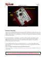
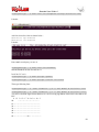
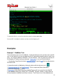
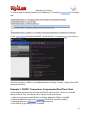
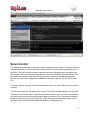
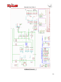
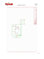
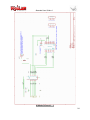
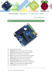
Alamode User Guide r1
AlaMode User Manual
Revision 1.0
www.wyolum.com
[email protected]
1
Alamode User Guide r1
Introduction
The AlaMode is an integrated Arduino compatible board. It is designed as versatile, general purpose data
acquisition and control module that stacks on the Raspberry Pi computer and provides a direct connection
to Raspberry Pi GPIO connector (26 pins).
The AlaMode includes AVR ATMEGA328P microcontrollers, precision real time clock (RTC), micro
SD card reader, reset button & standard shield headers. ATMEGA328P microcontroller includes the
Arduino bootloader and works as a bridge between Raspberry PI and Arduino. You can use the standard
ARDUINO environment and graphical interface for Windows or Linux for the software development and
programming this chip through ISP connector or Serial interface (USB to Serial TTL converter).
ATMEGA328P is connected to Raspberry Pi with I2C, SPI & Serial UART. In AlaMode ATMEGA328P
is slave device on I2C bus and Raspberry PI is a master. AlaMode board includes 3V-5V buffers to
connect Raspberry Pi with ATMEGA328P. In AlaMode ATMEGA328P uses 5V signal level.
It provides an easy way to add analog sensors, servos (see user contributed notes here), GPS modules, etc.
Since the board has standard ARDUINO connectors, it allows direct connections to the shields specially
made for Arduino. Its footprint is similar to that of Raspberry Pi.
Main Features of AlaMode:
1.
2.
3.
4.
5.
6.
7.
8.
9.
10.
11.
12.
13.
14.
15.
16.
Programmable directly from the Raspberry Pi GPIO, no cables required
The temperature-controlled precision Real Time Clock (RTC) DS3231 with battery backup
The micro SD Card reader
Two-way voltage level shifting for safe and accurate communication between Raspberry Pi and
AlaMode
The GPS interface for Fastrax UP501 module
Arduino Uno compatible with standard shield header.
AVR ATMEGA328P microcontroller which includes the Arduino bootloader
Interfaces with Raspberry Pi computer via I2C, SPI or Serial UART
Analog reference can be set to either 5V0 or 3V3 and GND headers to allow interfacing three
wires directly
Servo headers with 5V0 and GND connections to allow interfacing of 3 wire servos directly.
Servos can be powered via onboard 5V0 or from external 5V0
FTDI (5V0) or ISP headers for programming & loading sketches
Power via external 5V0 to micro-USB socket or directly from Raspberry Pi header.
5V0 and 3V3 indicator light
Reset button.
General purpose LED on digital pin 13
2
Alamode User Guide r1
Front view of the board
Instructions for safe use:
●
●
●
●
●
●
●
Please supervise children using the AlaMode
This product should be operated in a well-ventilated environment.
This product should be placed on a stable, flat, non-conductive surface in use and
should not be contacted by conductive items.
During operation do not expose it to water, moisture or place on a conductive surface.
Take care while handling to avoid mechanical or electrical damage to printed circuit
board.
Do not connect or disconnect AlaMode from Raspberry Pi while connected to power
supply.
Please observe electrostatic discharge (ESD) best practice when handling.
Use of Fonts:
Normal text ~ Arial
Terminal Interaction ~ Courier New with grey background. Each line is
prefixed with the command prompt “pi@raspberrypi ~ $” which you do not
type.
3
Alamode User Guide r1
Rear view of the board
Hardware Assembly
You will receive AlaMode hardware without headers installed. The headers are similar to the one used in
Arduino Uno R3. The headers are supplied as a kit and can be soldered if you would like to be able to use
standard Arduino shields. If you do not plan to use a shield, a low profile can be maintained by installing
right angle headers instead.
For experienced solderers, it should take 5 - 10 minutes to solder the headers. For beginners, do not
worry...It will only take you a little longer, about 15 minutes, to solder the headers to the AlaMode.
PRO TIP: push the headers onto the pins of an Arduino Shield before soldering. This holds them
perfectly aligned while you solder them in.
Turn the AlaMode upside down where you will find round slot ,i.e., coin type battery holder. If your
application requires, you can maintain time information between reboots by populating the RTC backup
battery CR1632:
http://www.digikey.com/product-detail/en/CR1632/P036-ND/269743.
This will also supply 3.3V backup to both RTC as well as GPS. Now your Alamode is ready to for
experimenting.
Note: Pay attention to the polarity markings on the holder and battery
4
Alamode User Guide r1
Install Arduino IDE for Raspberry Pi
We recommend you download either the latest version of Raspbian Wheezy from the download site of
www.raspberrypi.org or Occidentalis, which is distributed by Adafruit and is based on Raspbian Wheezy.
The instructions given below should work for either version. These instructions assume you have your
Raspberry Pi connected to the internet. You will find the icon for LX Terminal on your desktop
.
LX Terminal in Raspbian
Open LXTerminal and type following commands:
pi@raspberrypi ~ $ sudo apt-get update
pi@raspberrypi ~ $ sudo apt-get install arduino
To make the necessary changes for the Arduino IDE to recognize AlaMode, download AlaMode set up
from the link given below.
https://github.com/wyolum/alamode/raw/master/bundles/alamode-setup.tar.gz
From the command line, unpack and install it:
pi@raspberrypi ~ $ tar -xvzf alamode-setup.tar.gz
pi@raspberrypi ~ $ cd alamode-setup
pi@raspberrypi ~ $ sudo ./setup
The above lines will install Arduino IDE and get it ready to work with the AlaMode. The standard install
will work out of the box with any Arduino-compatible board that has an FTDI interface, but Uno's /dev/
ttyACM0 and the Raspberry Pi /dev/ttyAMA0 are not recognized by Arduino IDE. To do that we have
created some "udev rules" that create symbolic links to those devices that are named /dev/tty/S1(Uno) and
/dev/ttyS0 (AlaMode) respectively.
Interfacing with Raspberry Pi & Powering Up
AlaMode comes with built-in matching 26 pins female header and for direct interfacing with Raspberry Pi
through GPIO pins. A bit of care is required when putting the two devices together. It is easy to insert just
one row of pins into the socket, but all of the pins need to be connected.
The following GPIO pins available to AlaMode are I2C, SPI, UART, GND, 3V3, 5 V 0, GPIO pin # 1 for
reset. It is advised to interface both the devices without connecting to power.
5
Alamode User Guide r1
The AlaMode can be powered in three ways:
(1) Directly from Raspberry Pi, you can put jumper on the pins labeled “5V_Link” to the ON position.
With this jumper in this position, the AlaMode gets its power through the GPIO interface, so you will
need a power supply for the Raspberry Pi (RPi) that is capable of supplying a current of at least 1A.
5V_Link in ON position.
6
Alamode User Guide r1
5V_Link in OFF position.
(2) From external source by connecting it to 5V0 using micro USB port available on the other side of the
board. In this case the “5V_Link” jumper has to be put in OFF position.
(3) Using a 5V FTDI cable. In this case the “5V_Link” jumper has to be put in OFF position.
Note: Do not connect the power supply to the power connectors if you use the FTDI for
the communications with AVR ATMEGA328P microcontroller. FTDI cable or USB to
Serial converter will provide USB 5V power to board.
Once you interface and power up, you will note that LED light D1 and D2 are glowing. which indicates
AlaMode is powered.
Let's test AlaMode using Simple Blink Test to get you going.
Open Arduino IDE.
If AlaMode is directly connected to Raspberry Pi through GPIO connector, then
●
Select in Arduino menu: Tools ->Board -> AlaMode
7
Alamode User Guide r1
●
Tools -> Serial Port -> /dev/ttyS0
8
Alamode User Guide r1
●
File - > Examples - > Basics - > Blink.
The Blink sketch is loaded into the IDE. Now press the upload icon or press cntrl + u to upload the
sketch to AlaMode. You will see the green LED D6 is blinking, which means AlaMode is working.
(2) If you are using a 5V FTDI cable (check the connection), then
● Select
in Arduino menu: Tools ->Board -> UNO
● Tools -> Serial Port -> /dev/ttyUSB0
● File - > Examples - > Basics - > Blink.
Adding RTC of AlaMode as real time hardware clock for Raspberry Pi
via I2C. (Appreciation to AdaFruit Industries for providing the tutorial.
This is simply a re-writing of that tutorial).
It is possible to use AlaMode’s RTC as a real time hardware clock for Raspberry Pi. For this you need
LXTerminal. Since the DS3231 and the SD 1307 follow the same protocol, we can follow the excellent
tutorial provided by AdaFruit Industries.
First you have to get the I2C drivers into the kernel and assuming the user is using the Raspbian distro
which already has it in, but unfortunately it is disabled so you have to add comment (#) before the two
lines. Follow the steps on LXTerminal as shown below:-
9
Alamode User Guide r1
pi@raspberrypi ~ $ sudo nano /etc/modprobe.d/raspi-blacklist.conf
Like this:
Add # in front of two lines as shown below…
#blacklist spi-bcm2708
#blacklist i2c-bcm2708
Like this:
Press cntrl + x and press y to save it.
pi@raspberrypi ~ $ sudo nano /etc/modules
and add i2c-dev at the last line and save it.
Install the I2C tools:
pi@raspberrypi ~ $ sudo apt-get update
pi@raspberrypi ~ $ sudo apt-get install i2c-tools
Then type following lines:
pi@raspberrypi ~ $ sudo i2cdetect –y 0 // RPi Model B revision 1 brd
pi@raspberrypi ~ $ sudo i2cdetect –y 1 // RPi Model B revision 2 brd
You will see from the figure below that there is a device occupying address 0x68 which is the address for
RTC.
0 1 2 3 4 5 6 7 8 9 a b c d e f
00:
-- -- -- -- -- -- -- -- -- -- -- -- -10: -- -- -- -- -- -- -- -- -- -- -- -- -- -- -- -20: -- -- -- -- -- -- -- -- -- -- -- -- -- -- -- -30: -- -- -- -- -- -- -- -- -- -- -- -- -- -- -- -40: -- -- -- -- -- -- -- -- -- -- -- -- -- -- -- -50: -- -- -- -- -- -- -- -- -- -- -- -- -- -- -- -60: -- -- -- -- -- -- -- -- 68 -- -- -- -- -- -- -10
Alamode User Guide r1
70: -- -- -- -- -- -- -- -Continuing the tutorial, let’s load up the RTC module by running the following command:
pi@raspberrypi ~ $ sudo modprobe rtc-ds1307
The following commands need to be run as root. The command “sudo bash” changes to the root user.
And “exit” returns you to normal user mode.
pi@raspberrypi ~ $ sudo bash
root@raspberrypi: /home/pi # echo ds1307 0x68 > /sys/class/i2cadapter/i2c-0/new_device // for revision 1 board.
oot@raspberrypi: /home/pi # echo ds1307 0x68 > /sys/class/i2cadapter/i2c-1/new_device // for revision 2 board.
oot@raspberrypi: /home/pi # exit
If everything goes well, then you can check the hwclock time. If the time is not correct or if you are not
connected to internet, you can set the time by running following script:
It will set this time to hwclock and once the time is correct, check it with date command.
pi@raspberrypi ~ $
sudo hwclock ––set ––date=”2013-01-31 20:00:00”
If you are connected to the internet, you can instead update the RTC from the system time:
pi@raspberrypi ~ $ sudo hwclock –w
and verify it with
pi@raspberrypi ~ $ sudo hwclock –r.
Next time you will like to add the RTC kernel module to the /etc/modules list, so it is loaded
automatically when the machine boots. For this, run
pi@raspberrypi ~ $ sudo nano /etc/modules
and add rtc-ds1307 at the last line i.e. after i2c-dev and save it.
11
Alamode User Guide r1
It is also required to create the DS1307 device creation at boot, edit /etc/rc.local by running
pi@raspberrypi ~ $
sudo nano /etc/rc.local
And add after line containing fi (note “\” is a continuation line that means the command continues on the
next line)
pi@raspberrypi ~ $ sudo modprobe rtc-ds1307
pi@raspberrypi ~ $ echo ds1307 0x68 > \
/sys/class/i2c-adapter/i2c-0/new_device // for revision 1 board.
pi@raspberrypi ~ $ echo ds1307 0x68 > \
/sys/class/i2c-adapter/i2c-1/new_device // for revision 2 board.
pi@raspberrypi ~ $ sudo hwclock -r
before “exit 0” and save it.
see the screenshot in the next page.
12
Alamode User Guide r1
To make this effective, you need to reboot the system by running sudo reboot.
Now, the RTC of AlaMode is added as real time clock for Raspberry Pi.
Examples
Example 1: AlaMode Test
This is the factory test we use for AlaMode. It tests the Serial port, I2C, real time clock, and SD
card. A side benefit is you can see both sides (the Pi side and the AlaMode side) of each of the
ports. I am using the AdaFruit “WebIDE” to run this example. This is a great way to develop on
the Raspberry Pi without setting up a display. Give it a try, or use your favorite method.
1. Download or Copy/Paste the sketch AlaModeTest.ino (or get the raw file) from bitbucket into
the Arduino IDE.
2. Upload the sketch to AlaMode by clicking the button with the right arrow on it:
.
3. Download pyserial 2.5 and install pyserial. This is a super easy library that allows
connections through any serial port.
4. Download or Copy/Paste the python AlaModeTester.py file into a new file in the WebIDE.
5. Run AlaModeTester.py by clicking “Run” in WebIDE. Success! (Mostly.) I did not have an
SD card installed in AlaMode at the time of the test. The SD test is run on the AlaMode once
13
Alamode User Guide r1
at boot up. To retest, insert an uSD card in the AlaMode, then hit reset on the AlaMode, then
rerun the test by clicking “Run” in WebIDE.
Example 2: Firmata Blink
This is only useful if the Raspberry Pi and the AlaMode can interact. The Firmata library is a
messaging handling protocol that takes a lot of the difficulty out of two-platform development
while only having to develop code on one the Pi side of the interface. Firmata can also be
extended on the AlaMode side of the interface to set up special message handling. 1. First
start the Arduino IDE.
pi@raspberrypi ~ $ /usr/bin/arduino &
(The “&” in the above line “backgrounds” the arduino process, so that you can still use the
command line.)
2. When Arduino comes up, this can take 15 - 20 seconds.
14
Alamode User Guide r1
Open File--> Examples--> Firmata → StandardFirmata.
Make sure your selected board is “AlaMode” with serial port “/dev/ttyS0”.
3. Upload the sketch by clicking the button with the right arrow on it:
not run very quickly on the Raspberry Pi, so this takes about a minute.
. The compiler does
15
Alamode User Guide r1
4. Now we need to install pyFirmata on the Raspberry Pi. Extract the source code to “/home/pi/
tmp”.
pi@raspberrypi ~ $ mkdir tmp # no harm if already exists
pi@raspberrypi ~ $ cd tmp
pi@raspberrypi ~/tmp $ wget \
https://bitbucket.org/tino/pyfirmata/get/3f54748b2154.zip
pi@raspberrypi ~/tmp $ unzip 3f54748b2154.zip
…
pi@raspberrypi ~/tmp/... $ sudo /usr/bin/python2.7 setup.py install
5. Run pyFirmataTest through the WebIDE. (Create New File, copy/paste code), then click run.
If all went correctly, an LED on your AlaMode should be blinking! Hooray! Today a blinky LED,
tomorrow the World!
Example 3: DS3231 Temperature Compensated Real Time Clock
In this example we access the time from the DS3231 real time clock. Since it is connected
directly to the I2C bus, we need play only with the Pi side of the house.
1. Make a new directory called DS3231 by clicking “Make New Folder” in WebIDE.
2. Download AdaFruit’s easy-to-use I2C library into DS3231 (created in step #1)
3. Download WyoLum’s DS3231.py into the same directory.
4. Run DS3231.py by clicking “Run” in WebIDE.
16
Alamode User Guide r1
Servo Control
The AlaMode board provides a convenient way to connect to servo motors. The photo of the top
of the board shows an area labeled Servo 5V0 and GND. This area of the board has 8 sets of
three pins. The first six sets are used to control servo motos; the remaining 2 sets select your
power option. Each set of three pins has Ground, 5Vdc, and a PWM pin from the Arduino. The
pin closest to the Arduino chip is the PWM pin; the pin furthest from the Arduino chip is the
Ground. Counting from the edge of the AlaMode the PWM pins are D3, D5, D6, D9, D10 and
D11.
To connect a servo you push its three wire connector onto a set of pins. Be sure the orientation
is correct.
You have two choices for 5V power to your servos. This choice is made using the last two sets
of three pins: set 7 and 8. Rows 7 and 8 have identical function. You can select servo power by
using only one of the two rows and leaving the other row empty. Or you can place an identical
jumper in both rows to give you more current. (This document has an excellent photo of how
this works http://wyolum.com/docs/Alamode/AlaMode_V1datasheet.pdf)
17
Alamode User Guide r1
Using Board Power - By putting a jumper between the middle pin and the one closest to the
Arduino chip you select to use the same 5V power as the AlaMode board is using. If your
AlaMode board is using power from the Raspberry Pi GPIO connector, then you will not have
much power left for your servos. If you are powering your AlaMode from its own mini USB
connector then you can supply enough power to run several small servos.
Using Off Board Power - Your second choice for powering the servos is to remove the jumpers
from rows 7 and 8. Instead you can connect an external 5Vdc power supply to the pins in rows 7
and 8. Ground connects to pin furthest from the Arduino chip and +5vdc connects to the center
pin. The pin closest to the Arduino will not be used.
The Arduino IDE has a sample program for controlling servo motors.
AlaMode continues to reset - If you find that your AlaMode board resets when your servos are
running with on board power, then you are overloading your power supply. Moving the servos
is pulling your power supply voltage low enough that the Arduino resets. You should either use
smaller servos, use fewer servos, or get a more powerful power supply. You should be able to
run six micro servos with a 2.1A power supply.
18
Alamode User Guide r1
Schematics:
We have included the schematics for the AlaMode in the following pages for further reference.
19
Alamode User Guide r1
AlaMode Schematic - 1
20
Alamode User Guide r1
AlaMode Schematic - 2
21
Alamode User Guide r1
22
Alamode User Guide r1
AlaMode Schematic - 3
23
Alamode User Guide r1
AlaMode Schematic - 4
24
Alamode User Guide r1
25