1
GRYPHON™
Reference Manual
90ACC1780
GRYPHON™
REFERENCE MANUAL
DATALOGIC S.p.A.
Via Candini 2
40012 - Lippo di Calderara di Reno
Bologna - Italy
Gryphon™
Ed.: 05/2006
This manual refers to software version 3.1.0 and later
ALL RIGHTS RESERVED
Datalogic reserves the right to make modifications and improvements without prior notification.
Datalogic shall not be liable for technical or editorial errors or omissions contained herein, nor for incidental
or consequential damages resulting from the use of this material.
Product names mentioned herein are for identification purposes only and may be trademarks and or
registered trademarks of their respective companies.
© Datalogic S.p.A. 2000 -2006
Rev. G
CONTENTS
GENERAL VIEW ....................................................................................... viii
1
INTRODUCTION .......................................................................................... 1
2
2.1
2.2
2.3
2.4
2.5
2.6
2.7
2.8
2.8.1
2.8.2
2.8.3
INSTALLATION............................................................................................ 2
GRYPHON™ D Interface Cable Connections............................................... 2
OM-GRYPHON™ Interface Cable Connections ........................................... 3
RS232 Connection ........................................................................................ 4
USB .............................................................................................................. 4
IBM USB POS............................................................................................... 5
WEDGE Connection ..................................................................................... 5
PEN Emulation Connection........................................................................... 6
GRYPHON™ M Battery Maintenance........................................................... 7
Battery Type.................................................................................................. 7
Battery Charging ........................................................................................... 7
Replacing GRYPHON™ M Batteries ............................................................ 7
3
3.1
3.1.1
3.1.2
3.1.3
3.2
3.2.1
GRYPHON™ M SYSTEM AND NETWORK LAYOUTS ................................ 9
Stand Alone Layouts ..................................................................................... 9
Single Reader Layout.................................................................................... 9
Multiple Reader Layout ................................................................................. 9
Multiple Stand Alone Layouts...................................................................... 10
Multidrop STAR-System™ Network Layouts............................................... 11
Host Master Layout ..................................................................................... 11
4
4.1
4.1.1
4.1.2
4.1.3
4.1.4
4.2
4.3
4.4
4.4.1
4.4.2
4.5
4.6
4.7
4.8
CONFIGURATION...................................................................................... 12
Configuration Methods ................................................................................ 12
Reading Configuration Barcodes ................................................................ 12
Using DL Sm@rtSet.................................................................................... 12
Copy Command .......................................................................................... 12
Sending Configuration Strings from Host .................................................... 13
Setup Procedures ....................................................................................... 13
GRYPHON™ D Setup ................................................................................ 14
GRYPHON™ M/OM-GRYPHON™ Stand Alone Setup .............................. 14
Using Multiple M-Series Readers With Same Cradle.................................. 16
GRYPHON™ M/STAR-Modem™ in Stand Alone Mode ............................. 17
GRYPHON™ M/STAR-System™ Setup..................................................... 18
Interface Selection ...................................................................................... 20
USB Reader Configuration.......................................................................... 25
Changing Default Settings .......................................................................... 28
iii
RS232 PARAMETERS ............................................................................... 29
Baud Rate ................................................................................................... 30
Parity........................................................................................................... 31
Data Bits ..................................................................................................... 31
Stop Bits...................................................................................................... 32
Handshaking ............................................................................................... 32
Ack/Nack Protocol....................................................................................... 33
FIFO............................................................................................................ 33
Inter-character Delay................................................................................... 34
Rx Timeout.................................................................................................. 34
Serial Trigger Lock...................................................................................... 35
USB PARAMETERS .................................................................................. 36
Handshaking ............................................................................................... 37
Ack/Nack Protocol....................................................................................... 37
FIFO............................................................................................................ 38
Inter-character Delay................................................................................... 38
Rx Timeout.................................................................................................. 39
Serial Trigger Lock...................................................................................... 39
Keyboard Nationality ................................................................................... 40
FIFO............................................................................................................ 41
Inter-character Delay................................................................................... 41
Inter-code Delay.......................................................................................... 42
WEDGE PARAMETERS............................................................................. 43
Keyboard Nationality ................................................................................... 44
Caps Lock ................................................................................................... 45
Caps Lock Auto-Recognition (IBM AT compatible only)............................... 45
Num Lock.................................................................................................... 46
Inter-character Delay................................................................................... 46
Inter-code Delay.......................................................................................... 47
Keyboard Setting......................................................................................... 48
PEN EMULATION ...................................................................................... 50
Operating Mode .......................................................................................... 51
Minimum Output Pulse................................................................................ 52
Conversion to Code 39 and Code 128 ........................................................ 53
Overflow...................................................................................................... 54
Output Level................................................................................................ 54
Idle Level..................................................................................................... 55
Inter-Block Delay......................................................................................... 55
IBM 46xx .................................................................................................... 56
IBM Data Formatting................................................................................... 57
iv
DATA FORMAT .......................................................................................... 58
Code Identifier............................................................................................. 61
Custom Code Identifier ............................................................................... 62
Header ........................................................................................................ 63
Terminator................................................................................................... 64
Field Adjustment ......................................................................................... 65
Field Adjustment Character......................................................................... 66
Code Length Tx .......................................................................................... 66
Character Replacement .............................................................................. 67
Address Stamping (M Series Only) ............................................................. 69
Address Delimiter (M Series Only) .............................................................. 69
POWER SAVE............................................................................................ 70
Scan Rate ................................................................................................... 71
Sleep State/USB Suspend .......................................................................... 71
Enter Sleep Timeout ................................................................................... 72
Standby....................................................................................................... 72
READING PARAMETERS.......................................................................... 73
Operating Mode .......................................................................................... 74
Hand-Held Operation .................................................................................. 74
Stand Operation.......................................................................................... 75
Hardware Trigger Mode .............................................................................. 75
Trigger-off Timeout ..................................................................................... 75
Flash Mode ................................................................................................. 76
Reads per Cycle.......................................................................................... 76
Safety Time................................................................................................. 77
Beeper Intensity .......................................................................................... 77
Beeper Tone ............................................................................................... 78
Beeper Type ............................................................................................... 78
Beeper Length ............................................................................................ 78
PDF Decoding Recognition Intensity........................................................... 79
Good Read Spot Duration........................................................................... 79
DECODING PARAMETERS....................................................................... 80
Ink Spread................................................................................................... 81
Overflow Control ......................................................................................... 81
Interdigit Control.......................................................................................... 82
Decoding Safety.......................................................................................... 82
Puzzle Solver™ .......................................................................................... 83
CODE SELECTION .................................................................................... 84
EAN/UPC Family ........................................................................................ 86
2/5 Family ................................................................................................... 90
Code 39 Family........................................................................................... 91
Code 128 Family ......................................................................................... 93
v
Code 93 ...................................................................................................... 94
Codabar Family........................................................................................... 95
MSI ............................................................................................................. 97
Plessey ....................................................................................................... 98
Telepen ....................................................................................................... 99
Delta IBM .................................................................................................. 100
Code 11 .................................................................................................... 101
Code 16K .................................................................................................. 102
Code 49 .................................................................................................... 102
PDF417..................................................................................................... 103
RSS Codes ............................................................................................... 104
ADVANCED FORMATTING ..................................................................... 105
Concatenation........................................................................................... 106
Advanced Formatting ................................................................................ 109
RADIO PARAMETERS............................................................................. 124
Radio Protocol Timeout............................................................................. 125
Power-Off Timeout .................................................................................... 125
Beeper Control for Radio Response ......................................................... 126
Battery Type.............................................................................................. 126
Single Store .............................................................................................. 127
5
5.1
5.1.1
5.1.2
5.1.3
5.1.4
5.2
5.2.1
5.2.2
5.2.3
5.2.4
5.2.5
5.3
5.3.1
5.4
5.4.1
5.4.2
5.4.3
5.4.4
5.5
5.5.1
5.5.2
5.5.3
vi
REFERENCES ......................................................................................... 128
RS232 Parameters ................................................................................... 128
Handshaking ............................................................................................. 128
ACK/NACK Protocol ................................................................................. 129
FIFO.......................................................................................................... 130
RX Timeout ............................................................................................... 131
Pen Parameters ........................................................................................ 131
Minimum Output Pulse.............................................................................. 131
Conversion to Code 39 and Code 128 ...................................................... 131
Overflow.................................................................................................... 132
Output and Idle Levels .............................................................................. 132
Inter-Block Delay....................................................................................... 133
IBM 46xx Parameters................................................................................ 133
IBM Data Formatting (Transmission Format) ............................................ 133
Data Format .............................................................................................. 134
Header/Terminator Selection .................................................................... 134
Set Custom Extended Header/Terminator Keys ....................................... 136
Address Stamping..................................................................................... 138
Address Delimiter...................................................................................... 138
Power Save............................................................................................... 138
Sleep State/USB Suspend ........................................................................ 138
Enter Sleep Timeout ................................................................................. 139
Standby..................................................................................................... 139
5.6
5.6.1
5.6.2
5.6.3
5.6.4
5.6.5
5.7
5.7.1
5.7.2
5.7.3
5.8
5.8.1
5.8.2
5.8.3
5.8.4
5.9
5.10
5.10.1
5.10.2
5.10.3
5.11
5.12
Reading Parameters ................................................................................. 139
Operating Mode ........................................................................................ 139
Hardware Trigger Mode ............................................................................ 140
Trigger-Off Timeout................................................................................... 140
Reads per Cycle........................................................................................ 140
Safety Time............................................................................................... 141
Decoding Parameters ............................................................................... 141
Ink-Spread ................................................................................................ 141
Overflow Control ....................................................................................... 141
Interdigit Control........................................................................................ 141
Radio Parameters (M SEries Only) ........................................................... 142
Radio Protocol Timeout............................................................................. 142
Power-Off Timeout .................................................................................... 142
Beeper Control for Radio Response ......................................................... 142
Single Store .............................................................................................. 143
Configuration Editing Commands.............................................................. 144
Configuration Copying Commands ........................................................... 145
Copy GRYPHON™ D-Series..................................................................... 145
Copy GRYPHON™ M-Series .................................................................... 146
Copy OM-GRYPHON™ ............................................................................ 147
C-GRYPHON™ Configuration .................................................................. 148
Default Parameters for POS Terminals..................................................... 149
6
6.1
6.2
6.3
6.4
6.5
6.6
TECHNICAL FEATURES ......................................................................... 150
GRYPHON™ D......................................................................................... 150
GRYPHON™ M ........................................................................................ 151
OM-GRYPHON™ / C-GRYPHON™......................................................... 152
System and Radio Features...................................................................... 153
Status Indicators ....................................................................................... 153
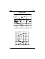
Reading Diagrams .................................................................................... 155
A
HOST CONFIGURATION STRINGS ........................................................ 157
B
CODE IDENTIFIER TABLE...................................................................... 170
C
HEX AND NUMERIC TABLE ................................................................... 173
vii
GENERAL VIEW
GRYPHON™ D/M READERS
Gryphon™ D
Cable Connector
Gryphon™ M
Battery Cover
Trigger
LED
Reading
Window
Figure A – Gryphon™ D and M Series Readers
Battery
Reconditioning Button
LEDs
Figure B – OM-GRYPHON™ and C-GRYPHON™
viii
INTRODUCTION
1
1
INTRODUCTION
Datalogic has moved a step ahead in the concept of “instinctive reading. ”The new
Gryphon™ reader has been developed to provide optimised reading performance
through excellent ergonomic design, a natural instinctive reading approach and
innovative good reading feedback.
The “INSTINCTIVE READING DISTANCE,” a concept introduced by Datalogic a few
years ago based on in-depth ergonomic studies, represents the natural position of the
user while reading a code. The Gryphon™ series takes this concept one step
further. The series includes two tethered (D100 and D200) and two cordless (M100
and M200) models, allowing operations anywhere mobility is required at the
desk/POS and around the shop floor, as well as in a small warehouse. The new
“green spot,” (Datalogic patent application) produced by the Gryphon™ provides
“good reading” feedback directly on the code, where the user usually tends to be
looking. Correct pointing becomes quick and easy thanks to the sharp and bright
illumination line. All these characteristics are coupled with outstanding performance in
terms of reading quickness and decoding capability thanks to state-of-the-art optics
and a decode rate of 270 scans/sec, making the Gryphon™ very user friendly,
intuitive and fast.
Specially optimised optics allow reading of the most popular standard codes with
superior depths of field from near contact to over 30 cm. High resolution codes, which
can reach 3 mils are also easily read. Two specific models of the Gryphon™ series
(D200 and M200) have also been designed to provide decoding of the PDF417, as
well as traditional barcodes. The Gryphon™ reader series is paving the road for
innovative barcode reading.
1
GRYPHON™
2
2
INSTALLATION
Connections should always be made with power OFF!
CAUTION
2.1
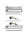
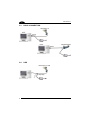
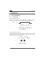
GRYPHON™ D INTERFACE CABLE CONNECTIONS
The Gryphon™ D reader incorporates a multi-standard interface which can be
connected to a Host by plugging the correct interface cable into the connector as
shown below.
To disconnect the cable, insert a paper clip or other similar object into the slot on the
reader battery cover while unplugging the cable from the Gryphon™ D body.
Connections should always be made with power OFF!
CAUTION
2
INSTALLATION
2.2
2
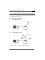
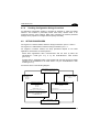
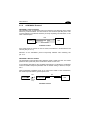
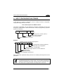
OM-GRYPHON™ INTERFACE CABLE CONNECTIONS
Interface Cable
Power Cable
OM-GRYPHON™ Connectors
The OM-GRYPHON™ incorporates a multi-standard interface which can be connected
to a Host by simply plugging the correct interface cable into the connector, placed on
the base of the cradle. In addition the cradle must be connected to an external power
supply.
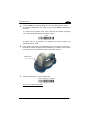
To disconnect the cable, insert a paper clip or other similar object into the hole
corresponding to the Host connector on the body of the cradle.
Push down on the clip while unplugging the cable.
Disconnecting the OM-GRYPHON™ Cable
3
GRYPHON™
2
2.3
RS232 CONNECTION
2.4
USB
(if required)
4
INSTALLATION
2.5
IBM USB POS
2.6
WEDGE CONNECTION
2
5
GRYPHON™
2
2.7
6
PEN EMULATION CONNECTION
INSTALLATION
2.8
2
GRYPHON™ M BATTERY MAINTENANCE
2.8.1
Battery Type
You can install NiMh, NiCd or Alkaline AA batteries in the Gryphon™ M.
2.8.2
Battery Charging
Once the system is connected and powered, you can place the Gryphon™ M into the
cradle to charge the battery.
When the scanner is correctly inserted in the cradle, the red LED on the cradle goes on
to indicate that the battery is charging. The green LED on the cradle goes on when the
battery is completely charged.
When using NiCd or NiMh batteries, frequent recharging before fully discharging can
cause a “memory effect” in which the batteries assume a reduced capacity.
Since it is not practical to wait for the reader to be fully discharged before recharging it,
the OM-Gryphon™ and the C-Gryphon™ are provided with a battery-reconditioning
feature which overcomes the “memory effect” problem.
To perform battery reconditioning, simply press the battery-reconditioning key on the
cradle control panel: the battery will be fully discharged in a short period of time (red
LED flashing), then automatically recharged.
We recommend performing the battery reconditioning once every few months or
whenever you feel the battery capacity has decreased.
2.8.3
Replacing GRYPHON™ M Batteries
To change the batteries in your Gryphon™ M scanner, proceed as follows:
1.
Unscrew the battery cover screw.
Battery
Cover Screw
7
GRYPHON™
2
2.
Open the battery cover.
Battery
Cover
3.
Replace the old batteries with new ones, then screw the battery cover back into
place.
-
+
NiMh, NiCd, or Alkaline AA Batteries
WARNING
8
Do not incinerate, disassemble, short terminals or expose to
high temperature. Risk of fire, explosion. Use specified
charger only. Risk of explosion if the battery is replaced by
an incorrect type. Dispose of the batteries as required by the
relevant laws in force.
GRYPHON™ M SYSTEM AND NETWORK LAYOUTS
3
3
GRYPHON™ M SYSTEM AND NETWORK LAYOUTS
There are two basic system layouts that can be employed: Stand Alone systems and
Multidrop STAR-System™ Networks.
3.1
STAND ALONE LAYOUTS
3.1.1
Single Reader Layout
3.1.2
Multiple Reader Layout
In stand alone systems, each cradle is connected to a single Host.
9
GRYPHON™
3
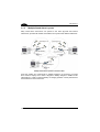
3.1.3
Multiple Stand Alone Layouts
Many stand alone connections can operate in the same physical area without
interference, provided all readers and cradles in the system have different addresses.
Multiple Stand Alone Systems in the Same Area
Since the cradles can communicate to multiple Gryphon™ M scanners, you might
find it useful to employ one or more C-Gryphon™ battery chargers in addition to the
OM-Gryphon™ cradle, so that the battery re-charging operation can be performed for
several scanners at the same time.
10
GRYPHON™ M SYSTEM AND NETWORK LAYOUTS
3.2
3
MULTIDROP STAR-SYSTEM™ NETWORK LAYOUTS
Even though many stand alone systems can operate in the same physical area without
interfering with each other, it may be desirable to bridge data from multiple base stations
in a network to a single Host. Gryphon™ M readers are compatible with
STAR-System™ networks. These networks provide seamless active roaming for any
RF reading device in the system.
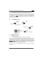
3.2.1
A.
B.
C.
Host Master Layout
Host Master with STAR-Link™
STAR-Box™ converter
STARGATE™ base stations
Example Multidrop STAR-System™ Network with Host as Master
In this layout the Host acts as the Master using STAR-Link™ software. The Host is
connected in RS232 to a STAR-Box™ converter which is connected to the first slave in
the RS485 network. In this way the base stations provide communications between a
single Host and all readers in the system. STARGATE™ base stations are used as
slaves in this network. The Slaves at the ends of the network must be terminated (see
the STARGATE™ and STAR-Box™ Installation Manuals).
See par. 4.5 and or the Sm@rtSet Help On-Line for system configuration
specifications.
11
GRYPHON™
4
4
CONFIGURATION
4.1
4.1.1
CONFIGURATION METHODS
Reading Configuration Barcodes
This manual can be used for complete setup and configuration of your reader by
following the setup procedures in this chapter (see par. 4.2 for an overview).
If you wish to change the default settings, this manual provides complete
configuration of your reader in an easy way.
To configure your reader:
1) Open the folded page in Appendix C with the hex-numeric table and keep it
open during the device configuration.
2) Read the Enter Configuration code ONCE, available at the top of each page
of configuration.
3) Modify the desired parameters in one or more sections following the
procedures given for each group.
4) Read the Exit and Save Configuration code ONCE, available at the top of
each page of configuration.
Reference notes describing the operation of the more complex parameters are given
in chapter 5.
4.1.2
Using DL Sm@rtSet
DL Sm@rtSet is a Windows-based utility program providing a quick and user-friendly
configuration method via the RS232 interface.
It also allows upgrading the software of the connected device (see the DL Sm@rtSet
User's Manual for more details).
4.1.3
Copy Command
A previously configured device (Master), can be used to send its configuration directly to
other devices of the same type (Slaves). The particular procedure for each device is
given in par. 5.10.
12
CONFIGURATION
4.1.4
4
Sending Configuration Strings from Host
An alternative configuration method is provided in Appendix A using the RS232
interface. This method is particularly useful when many devices need to be
configured with the same settings. Batch files containing the desired parameter
settings can be prepared to configure devices quickly and easily.
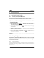
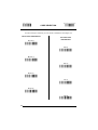
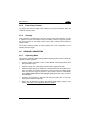
4.2
SETUP PROCEDURES
For Gryphon™ D-Series readers, follow the setup procedures in pars. 4.3 and 4.6.
For Gryphon™ D USB readers, follow the setup procedures in par. 4.7.
For Gryphon™ M-Series readers, the setup procedures depend on two basic
applications, Stand Alone or STAR-System™.
Stand Alone applications allow communication with the Host by either the
OM-Gryphon™ cradle (par. 4.4), or by the STAR-Modem™ radio modem
(par. 4.4.2).
STAR-System™ applications allow communication with the Host through an RS485
network by the STARGATE™ RF base station or by the STAR-Modem™ radio
modem (par. 4.5).
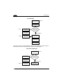
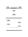
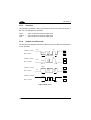
Proceed as shown in the following diagram:
B eg in S etu p by cho os ing the setup
procedure for your G R Y P H O N ™
reader as indicated below.
GRYPHON™ D
G RY PHO N ™ D U SB
P ar. 4.3
P ar. 4.6
P ar. 4.7
S ta n d Alo n e Ap p licatio n s
S TAR -S ystem ™ Ap p licatio n s
G R Y P H O N ™ M /O M -G R Y P H O N ™
G R Y P H O N ™ M /S T AR -S ystem ™
P ar. 4.4
P ar. 4.6
P ar. 4.5
O p tio n al P ar. 4.4.1
• S TA RG ATE ™
• S TA R-M odem ™ in STA R-System ™ M ode
m ultiple guns per O M -G R Y P H O N ™
G R Y P H O N ™ M /S T AR -M o d em ™
in S tand A lone M ode
P ar. 4.4.2
E n d o f S etu p
Y our reader is now ready to read
barcodes using the default settings.
13
GRYPHON™
4
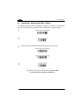
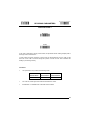
4.3
1.
GRYPHON™ D SETUP
Read the restore default parameters code below.
Restore Gryphon™ D Default
Ì$+$*oÎ
After reading the above code, go to par. 4.6 Interface Selection.
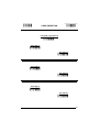
4.4
GRYPHON™ M/OM-GRYPHON™ STAND ALONE SETUP
Read the restore default parameters code below.
1.
2.
Restore Gryphon™M Default
Ì$+$*oÎ
Read the codes below to set the radio address of the Gryphon™ M reader.
Enter configuration
Ì$+;Î
3.
Set Radio Address
ÌRA0RFHÎ
+
four digits for the Gryphon™ M Address (from 0000 to 1999).
All readers used in the same area must have different addresses.
4.
14
Exit and Save configuration
Ì$-?Î
CONFIGURATION
5.
4
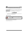
Read the Bind code to pair the Gryphon™ M to the OM-Gryphon™ cradle.
The reader is dedicated to the cradle. Any previously bound reader will be
excluded.
To connect several readers to the same cradle see the following paragraph
4.4.1, ‘Using Multiple M Readers with Same Cradle'.
Bind
Ì$+RN0$-IÎ
The green LED on the Gryphon™ M will blink; the reader is ready to be
positioned onto the cradle.
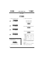
6.
Firmly position the reader onto the OM-Gryphon™ cradle within 10 seconds, a
beep will be emitted, signaling that the OM-Gryphon™ cradle has been paired
to the Gryphon™ M, and the green LED on the reader will go off.
Green LED
7.
Read the OM-Gryphon™ restore default code:
Restore OM-Gryphon™ default
Ì$+RX0$-qÎ
Go to par. 4.6 Interface Selection.
15
GRYPHON™
4
4.4.1
Using Multiple M-Series Readers With Same Cradle
If you want to use several M-Series readers with the same OM-Gryphon™ cradle,
you must first Bind the cradle with one of the readers (see previously described
configuration procedure).
Successive readers can be associated with the same cradle by following the
configuration procedure substituting the Bind command with Join (step 5).
Join
5.
Ì$+RN1$-NÎ
The green LED on the Gryphon™ M will blink: the reader is ready to be
positioned onto the cradle. Complete step 6.
END of procedure.
CAUTION
If the cradle is not Bound to a reader, its address assumes a
random value which can cause conflicts and malfunctions to other
cradles within its range.
YOUR READER IS NOW READY TO READ BARCODES.
To change the defaults see par. 4.8.
16
CONFIGURATION
4.4.2
4
GRYPHON™ M/STAR-Modem™ in Stand Alone Mode
To configure a Gryphon™ M reader to communicate with STAR-Modem™ in Stand
Alone Mode, follow the procedure in par. 4.4 substituting steps 4 and 5 with those
below:
STAR-Modem™ Address
4.
ÌRSRÎ
Read the code above and the four-digit address of the STAR-Modem™.
5.
Exit and Save configuration
Ì$-?Î
END of procedure.
YOUR READER IS NOW READY TO READ BARCODES.
To change the defaults see par. 4.8.
17
GRYPHON™
4
4.5
GRYPHON™ M/STAR-SYSTEM™ SETUP
The following procedure allows configuring a Gryphon™ M reader to communicate
with various STAR-System™ devices such as STARGATE™ RF base stations.
1.
Restore Gryphon™ M Default
2.
Enter configuration
3.
Ì$+$*oÎ
Ì$+;Î
Set the connection according to the length of the codes to be read:
Code Length ≤240 Characters
ÌRA1aÎ
Code Length >240 Characters
ÌRA2dÎ
4.
Set Radio Address
ÌRF8Î
+
four digits from the Numeric Table in the range 0000-1999.
All readers must have different addresses.
18
CONFIGURATION
4
First STAR-System™ Address
5.
ÌRSRÎ
Read the code above and the four-digit address of the First STAR-System™
device in the system.
Set Last STAR-System™ Address
6.
ÌRTTÎ
Read the code above and the four-digit address of the Last STAR-System™
device in the system.
NOTE
Whenever the system is composed of a single base station, the
first and last base station addresses (steps 5 and 6) must have
the same value.
Exit and Save Configuration
7.
Ì$-?Î
END of procedure.
YOUR READER IS NOW READY TO READ BARCODES.
To change the defaults see par. 4.8.
19
GRYPHON™
4
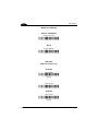
4.6
INTERFACE SELECTION
Read the interface selection code for your application.
RS232
Standard
Ì$+CP0$-$Î
POS Terminals
Nixdorf Mode A
Ì$+CM2EC0$->Î
Fujitsu
Ì$+CM1$-ÈÎ
ICL Mode
Ì$+CM0$-ÃÎ
For POS terminal default settings refer to par. 5.12.
PEN
Ì$+CP6$-BÎ
20
CONFIGURATION
4
WEDGE
IBM AT or PS/2 PCs
Ì$+CP500$-aÎ
IBM XT
Ì$+CP503$-vÎ
PC Notebook
Ì$+CP505$-ÈÎ
IBM SURE1
Ì$+CP506$-$Î
IBM Terminal 3153
Ì$+CP504$-}Î
21
GRYPHON™
4
WEDGE (CONTINUED)
IBM Terminals 31xx, 32xx, 34xx, 37xx:
To select the interface for these IBM Terminals, read the correct KEY
TRANSMISSION code. Select the KEYBOARD TYPE if necessary
(default = advanced keyboard).
KEY TRANSMISSION MODE
make-only keyboard
Ì$+CP502$-oÎ
make-break keyboard
Ì$+CP501$-hÎ
KEYBOARD TYPE
advanced keyboard
Ì$+FK1$-ÉÎ
typewriter keyboard
Ì$+FK0$-ÄÎ
22
CONFIGURATION
4
WEDGE (CONTINUED)
ALT MODE
The ALT-mode selection allows barcodes sent to the PC to be interpreted correctly
independently from the Keyboard Nationality used. You do not need to make a
Keyboard Nationality selection.
(default = Num Lock Unchanged). Make sure the Num Lock key on your
keyboard is ON.
IBM AT - ALT mode
Ì$+CP507$-+Î
PC Notebook - ALT mode
Ì$+CP508$-2Î
WYSE TERMINALS
ANSI Keyboard
Ì$+CP509$-9Î
PC Keyboard
Ì$+CP510$-gÎ
ASCII Keyboard
Ì$+CP511$-nÎ
VT220 style Keyboard
Ì$+CP514$-ÇÎ
23
GRYPHON™
4
WEDGE (CONTINUED)
DIGITAL TERMINALS
VT2xx/VT3xx/VT4xx
Ì$+CP512$-uÎ
APPLE
APPLE ADB Bus
Ì$+CP513$-|Î
IBM 46XX
(IBM 46xx models only)
PORT 9B
4501 Protocol
Ì$+CP800$-pÎ
(typical)
1520 Protocol
Ì$+CP801$-wÎ
PORT 5B
1520 Protocol
Ì$+CP801$-wÎ
(typical)
24
CONFIGURATION
4
4501 Protocol
Ì$+CP800$-pÎ
4.7
USB READER CONFIGURATION
The USB interface is compatible with:
Windows 98 (and later)
Mac OS 8.0 (and later)
IBM POS for Windows
4690 Operating System
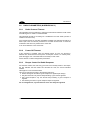
USB Start-up
As with all USB devices, upon connection, the Host performs several checks by
communicating with the USB device. During this phase the green LED on the device
blinks and normal operations are suspended. Two basic conditions must be met
before the USB device is ready to read codes, the correct USB driver must be loaded
and sufficient power must be supplied to the reader.
For all systems, the correct USB driver for the default USB-KBD interface is included
in the Host Operating System and will either be loaded automatically or will be
suggested by the O.S. and should therefore be selected from the dialog box (the first
time only).
If the Host supplies sufficient power to the reader, the start-up phase ends correctly,
the LED stops blinking and the reader emits the beep OK signal.
If the Host does not supply sufficient power to the reader, a dialog box will appear on
the Host and the reader will be blocked (LED continues blinking). In this case,
disconnect the USB device cable at the Host (LED stops blinking), connect and
power-up an external supply to the USB cable then reconnect the USB cable to the
Host and close the dialog box. The reader emits the beep OK signal. You can now
read codes. At this point you can read the USB interface configuration code
according to your application. Load drivers from the O.S. (if requested). When
configuring the USB-COM interface, the relevant files and drivers must be installed
from the USB Device Installation software which can be downloaded from the web
page http://www.datalogic.com.
The reader is ready.
25
GRYPHON™
4
First Start-Up
Connect device to
Host with USB cable
LED blinks
Load drivers
(if requested)
LED off
Disconnect reader
at Host
YES
Connect external
power supply to
cable and power up
BEEP OK
Does a dialog box
appear asking
whether Bus power
is sufficient?
NO
LED off - BEEP OK
Reconnect reader
cable to Host and
close dialog box
Select desired USB
interface code
Load drivers
(if requested)
Read test codes.
Reader is READY
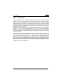
Successive start-ups will automatically recognize the previously loaded drivers. If
external power is used, verify that external power is already supplied.
Successive Start-Ups
Connect device to
Host with USB cable
Disconnect reader
at Host
Connect external
power supply to
cable and power up
YES
LED blinks
Does a dialog box
appear asking
whether Bus power
is sufficient?
NO
LED off - BEEP OK
BEEP OK
26
Reconnect reader
cable to Host and
close dialog box
Read test codes.
Reader is READY
CONFIGURATION
4
USB
USB-KBD
Ì$+UA03$-:Î
USB-KBD-ALT-MODE
Ì$+UA04$-@Î
USB-KBD-APPLE
Ì$+UA05$-FÎ
USB-COM*
Ì$+UA02$-4Î
USB-IBM-Table Top
Ì$+UA00$-(Î
USB-IBM-Hand Held
Ì$+UA01$-.Î
*
When configuring USB-COM, the relevant files and drivers must be installed from
the USB Device Installation software which can be downloaded from the web site
http://www.datalogic.com.
27
GRYPHON™
4
4.8
CHANGING DEFAULT SETTINGS
Once your reader is setup, you can change the default parameters to meet your
application needs. Refer to the preceding paragraphs for initial configuration in order
to set the default values and select the interface for your application.
In this manual, the configuration parameters are divided into logical groups making it
easy to find the desired function based on its reference group.
The RS232, WEDGE, PEN EMULATION groups are for Standard Interface
parameter
configuration
for
Gryphon™
D
series
readers
and
Gryphon™ M/OM-Gryphon™ Stand Alone configurations only:
The USB group is for Gryphon™ D USB only.
The IBM 46xx group is for IBM 46xx models only.
The following parameter groups are common to all interface applications:
DATA FORMAT parameters regard the messages sent to the Host system for all
interfaces except Pen Emulation.
POWER SAVE manages overall current consumption in the reading device.
READING PARAMETERS control various operating modes and indicator status
functioning.
DECODING PARAMETERS maintain correct barcode decoding in certain special
reading conditions.
CODE SELECTION parameters allow configuration of a personalized mix of codes,
code families and their options.
ADVANCED FORMATTING PARAMETERS allow code concatenation and advanced
formatting of messages towards the Host. It cannot be used with Pen Emulation
connections.
RADIO PARAMETERS (M series only) allow configuration of radio control
parameters.
28
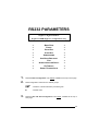
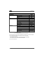
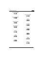
RS232 PARAMETERS
Gryphon™ D Series Readers
+
Gryphon™ M/OM-Gryphon™ configurations only
BAUD RATE
PARITY
DATA BITS
STOP BITS
HANDSHAKING
ACK/NACK PROTOCOL
FIFO
INTER-CHARACTER DELAY
RX TIMEOUT
SERIAL TRIGGER LOCK
1.
Read the Enter Configuration code ONCE, available at the top of each page.
2.
Read configuration codes from the desired groups.
= Read the code and follow the procedure given
= Default value
3.
Read the Exit and Save Configuration code ONCE, available at the top of
each page.
29
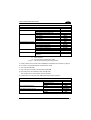
Enter Configuration
Ì$+;Î
Exit and Save Configuration
RS232
Ì$-?Î
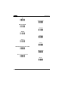
BAUD RATE
150 baud
ÌCDOKÎ
300 baud
ÌCD1XÎ
600 baud
ÌCD2[Î
1200 baud
ÌCD3^Î
2400 baud
ÌCD4aÎ
4800 baud
ÌCD5dÎ
9600 baud
ÌCD6gÎ
19200 baud
ÌCD7jÎ
38400 baud
ÌCD8mÎ
30
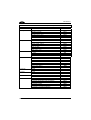
Enter Configuration
Ì$+;Î
Exit and Save Configuration
RS232
Ì$-?Î
PARITY
none
ÌCC0SÎ
even parity
ÌCC1VÎ
odd parity
ÌCC2YÎ
DATA BITS
7 bits
ÌCA0OÎ
8 bits
ÌCA1RÎ
9 bits
ÌCA2UÎ
31
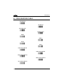
Enter Configuration
Ì$+;Î
Exit and Save Configuration
RS232
STOP BITS
1 stop bit
ÌCB0QÎ
2 stop bits
ÌCB1TÎ
HANDSHAKING
disable
ÌCE0WÎ
hardware (RTS/CTS)
ÌCE1ZÎ
software (XON/XOFF)
ÌCE2]Î
RTS always ON
ÌCE3`Î
See par. 5.1.1 for details.
32
Ì$-?Î
Enter Configuration
Ì$+;Î
Exit and Save Configuration
RS232
Ì$-?Î
ACK/NACK PROTOCOL
disable (sw 3.1.0)
ÌCF0YÎ
enable (sw 3.1.0)
ÌCF3bÎ
disable (sw 4.0 and later)
ÌER0sÎ
enable (sw 4.0 and later)
ÌER1vÎ
See par. 5.1.2 for details, particularly on implementing this parameter with Gryphon™ M.
FIFO
disable
ÌEC0UÎ
enable
ÌEC1XÎ
See par. 5.1.3 for details.
33
Enter Configuration
Ì$+;Î
Exit and Save Configuration
RS232
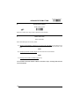
INTER-CHARACTER DELAY
delay between characters transmitted to Host
ÌCK3Î
Read 2 numbers from the table where:
00 = DELAY disabled
01-99 = DELAY from 1 to 99 milliseconds
delay disabled
RX TIMEOUT
timeout control in reception from Host
ÌCL5Î
Read 2 numbers from the table where:
00 = TIMEOUT disabled
01-99 = TIMEOUT from .1 to 9.9 seconds
rx timeout 5 seconds
See par. 5.1.4 for details.
34
Ì$-?Î
Enter Configuration
Ì$+;Î
Exit and Save Configuration
RS232
Ì$-?Î
SERIAL TRIGGER LOCK
disabled
ÌCR0qÎ
enable and select characters
ÌCR1tÎ
Read 2 characters from the Hex/Numeric table in the range 00-FE where:
−
−
First Character enables device trigger
Second Character inhibits device trigger until the first character is received again.
35
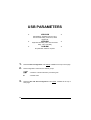
USB PARAMETERS
USB-COM
Handshaking, Ack/Nack protocol, FIFO,
Inter-character delay, Rx timeout, Serial
trigger lock
USB-KBD
Keyboard nationality, FIFO, Inter-character
delay, Inter-code delay
USB-IBM
No parameter selection required.
1.
Read the Enter Configuration code ONCE, available at the top of each page.
2.
Read configuration codes from the desired groups.
= Read the code and follow the procedure given
= Default value
3.
36
Read the Exit and Save Configuration code ONCE, available at the top of
each page.
Enter Configuration
Ì$+;Î
Exit and Save Configuration
USB-COM
Ì$-?Î
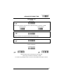
HANDSHAKING
disable
ÌCE0WÎ
hardware (RTS/CTS)
ÌCE1ZÎ
software (XON/XOFF)
ÌCE2]Î
RTS always ON
ÌCE3`Î
See par. 5.1.1 for details.
ACK/NACK PROTOCOL
disable
ÌER0sÎ
enable
ÌER1vÎ
See par. 5.1.2 for details.
37
Enter Configuration
Ì$+;Î
Exit and Save Configuration
USB-COM
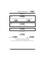
FIFO
disable
ÌEC0UÎ
enable
ÌEC1XÎ
See par. 5.1.3 for details.
INTER-CHARACTER DELAY
delay between characters transmitted to Host
ÌCK3Î
Read 2 numbers from the table where:
00 = DELAY disabled
01-99 = DELAY from 1 to 99 milliseconds
delay disabled
38
Ì$-?Î
Enter Configuration
Ì$+;Î
Exit and Save Configuration
USB-COM
Ì$-?Î
RX TIMEOUT
timeout control in reception from Host
ÌCL5Î
Read 2 numbers from the table where:
00 = TIMEOUT disabled
01-99 = TIMEOUT from .1 to 9.9 seconds
rx timeout 5 seconds
See par. 5.1.4 for details.
SERIAL TRIGGER LOCK
disabled
ÌCR0qÎ
enable and select characters
ÌCR1tÎ
Read 2 characters from the Hex/Numeric table in the range 00-FE where:
−
−
First Character enables device trigger
Second Character inhibits device trigger until the first character is received again.
39
Enter Configuration
Ì$+;Î
Exit and Save Configuration
USB-KBD
Ì$-?Î
KEYBOARD NATIONALITY
Not Available for USB-KBD-ALT-MODE Interface
This parameter default value is restored through the Interface Selection code and not Restore
Default.
Belgian
ÌFJ7yÎ
English
ÌFJ4pÎ
French
ÌFJ2jÎ
German
ÌFJ3mÎ
Italian
ÌFJ1gÎ
Japanese
ÌFJ8|Î
Spanish
ÌFJ6vÎ
Swedish
ÌFJ5sÎ
USA
ÌFJ0dÎ
40
Enter Configuration
Ì$+;Î
Exit and Save Configuration
USB-KBD
Ì$-?Î
FIFO
disable
ÌEC0UÎ
enable
ÌEC1XÎ
See par. 5.1.3 for details.
INTER-CHARACTER DELAY
delay between characters transmitted to Host
ÌCK3Î
Read 2 numbers from the table where:
00 = DELAY disabled
01-99 = DELAY from 1 to 99 milliseconds
delay disabled
41
Enter Configuration
Ì$+;Î
Exit and Save Configuration
USB-KBD
INTER-CODE DELAY
delay between codes transmitted to Host
ÌFG.Î
Read 2 numbers from the table where:
00 = DELAY disabled
01-99 = DELAY from 1 to 99 seconds
delay disabled
42
Ì$-?Î
WEDGE PARAMETERS
Gryphon™ D Series Readers
+
Gryphon™ M/OM-Gryphon™ configurations only
KEYBOARD NATIONALITY
CAPS LOCK
CAPS LOCK
AUTO-RECOGNITION
NUM LOCK
INTER-CHARACTER DELAY
INTER-CODE DELAY
KEYBOARD SETTING
1.
Read the Enter Configuration code ONCE, available at the top of each page.
2.
Read configuration codes from the desired groups.
= Read the code and follow the procedure given
= Default value
3.
Read the Exit and Save Configuration code ONCE, available at the top of
each page.
.
43
Enter Configuration
Ì$+;Î
Exit and Save Configuration
WEDGE
Ì$-?Î
KEYBOARD NATIONALITY
Belgian
ÌFJ7yÎ
English
ÌFJ4pÎ
French
ÌFJ2jÎ
German
ÌFJ3mÎ
Italian
ÌFJ1gÎ
Spanish
ÌFJ6vÎ
Swedish
ÌFJ5sÎ
USA
ÌFJ0dÎ
The Japanese Keyboard Nationality selection is valid only for IBM AT compatible PCs.
Japanese
ÌFJ8|Î
44
Enter Configuration
Ì$+;Î
Exit and Save Configuration
WEDGE
Ì$-?Î
CAPS LOCK
caps lock OFF
ÌFE0ZÎ
caps lock ON
ÌFE1]Î
Select the appropriate code to match your keyboard caps lock status.
Note:
Caps lock manual configuration is ignored when Caps Lock Auto-Recognition is
enabled.
For PC Notebook interface selections, the caps lock status is automatically recognized,
therefore this command is not necessary.
CAPS LOCK AUTO-RECOGNITION (IBM AT COMPATIBLE ONLY)
disable
ÌFP0pÎ
enable
ÌFP1sÎ
45
Enter Configuration
Ì$+;Î
Exit and Save Configuration
WEDGE
Ì$-?Î
NUM LOCK
toggle num lock
ÌFL1kÎ
num lock unchanged
ÌFL0hÎ
This selection is used together with the Alt Mode interface selection for AT or Notebook PCs.
It changes the way the Alt Mode procedure is executed, therefore it should be set as follows:
•
if your keyboard Num Lock is normally on use num lock unchanged
•
if your keyboard Num Lock is normally off use toggle num lock
In this way the device will execute the Alt Mode procedure correctly for your application.
INTER-CHARACTER DELAY
delay between characters transmitted to Host
ÌCK3Î
Read 2 numbers from the table where:
00 = DELAY disabled
01-99 = DELAY from 1 to 99 milliseconds
delay disabled
46
Enter Configuration
Ì$+;Î
Exit and Save Configuration
WEDGE
Ì$-?Î
INTER-CODE DELAY
delay between codes transmitted to Host
ÌFG.Î
Read 2 numbers from the table where:
00 = DELAY disabled
01-99 = DELAY from 1 to 99 seconds
delay disabled
47
Enter Configuration
Exit and Save Configuration
Ì$+;Î
WEDGE
Ì$-?Î
KEYBOARD SETTING
ALPHANUMERIC KEYBOARD SETTING
The reader can be used with terminals or PCs with various keyboard types and nationalities
through a simple keyboard setting procedure.
The type of computer or terminal must be selected before activating the keyboard setting
command.
Keyboard setting consists of communicating to the reader how to send data corresponding to
the keyboard used in the application. The keys must be set in a specific order.
Press and release a key to set it.
Some characters may require more than one key pressed simultaneously during normal use
(refer to the manual of your PC or terminal for keyboard use). The exact sequence must be
indicated to the reader in this case pressing and releasing the different keys.
Example:
If one has to press the "Shift" and "4" keys simultaneously on the keyboard to transmit the
character "$" to the video, to set the "$", press and release "Shift" then press and release "4".
Each pressed and released key must generate an acoustic signal on the reader, otherwise
repress the key. Never press more than one key at the same time, even if this corresponds to
the normal use of your keyboard.
Press "Backspace" to correct a wrong key entry. In this case the reader emits 2 beeps.
Note: "CAPS LOCK" and "NUM LOCK" must be off before starting the keyboard setting
procedure. "SHIFT" must be repressed for each character and cannot be substituted by
"CAPS LOCK".
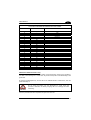
setting the alphanumeric keyboard
ÌFB0TÎ
Read the code above.
Press the keys shown in the following table according to their numerical order.
Some ASCII characters may be missing as this depends on the type of keyboard: these are
generally particular characters relative to the various national symbologies. In this case:
•
The first 4 characters (Shift, Alt, Ctrl, and Backspace) can only be substituted with
keys not used, or substituted with each other.
•
characters can be substituted with other single symbols (e.g. "SPACE") even if not
included in the barcode set used.
•
characters can be substituted with others corresponding to your keyboard.
The reader signals the end of the procedure with 2 beeps indicating the keys have been
registered.
48
WEDGE
01 : Shift
02 : Alt
03 : Ctrl
04 : Backspace
05 : SPACE
06 : !
07 : "
08 : #
09 : $
10 : %
11 : &
12 : '
13 : (
14 : )
15 : *
16 : +
17 : ,
18 : 19 : .
20 : /
21 : 0
22 : 1
23 : 2
24 : 3
25 : 4
26 : 5
27 : 6
28 : 7
29 : 8
30 : 9
31 : :
32 : ;
33 : <
34 : =
35 : >
36 : ?
37 : @
38 : A
39 : B
40 : C
41 : D
42 : E
43 : F
44 : G
45 : H
46 : I
47 : J
48 : K
49 : L
50 : M
51 : N
52 : O
53 : P
54 : Q
55 : R
56 : S
57 : T
58 : U
59 : V
60 : W
61 : X
62 : Y
63 : Z
64 : [
65 : \
66 : ]
67 : ^
68 : _ (underscore)
69 : `
70 : {
71 : |
72 : }
73 : ~
74 : DEL
GRYPHON™ M-Series Readers Only
When working with Gryphon™ M-Series readers, the keyboard setup functioning is signaled by
the LEDs on the OM-Gryphon™ cradle. Each key stroke corresponds to a double blinking of the
green LED.
By pressing the Backspace key the red LED on the OM-Gryphon™ cradle blinks, while the
green LED stays on.
Do not place the reader onto the OM-GRYPHON™ cradle during this
procedure. Otherwise, the battery charging will occur modifying the LEDs
functioning.
CAUTION
Once the procedure has been completed, the green LED turns off.
49
PEN EMULATION
Gryphon™ D Series Readers
+
Gryphon™ M/OM-Gryphon™ configurations only
OPERATING MODE
MINIMUM OUTPUT PULSE
CONVERSION TO CODE 39
OVERFLOW
OUTPUT LEVEL
IDLE LEVEL
INTER-BLOCK DELAY
1.
Read the Enter Configuration code ONCE, available at the top of each page.
2.
Read configuration codes from the desired groups.
= Default value
3.
50
Read the Exit and Save Configuration code ONCE, available at the top of
each page.
PEN EMULATION
The operating mode parameters are complete commands and do not require reading the
Enter and Exit configuration codes.
OPERATING MODE
interpret mode
Ì$]8Î
Interprets commands without sending them to the decoder.
transparent mode
Ì$[4Î
Sends commands to the decoder without interpreting them.
51
Enter Configuration
Ì$+;Î
Exit and Save Configuration
PEN EMULATION
Ì$-?Î
MINIMUM OUTPUT PULSE
high resolution code
emulation
200 µs
ÌDG0\Î
400 µs
ÌDG1_Î
600 µs
ÌDG2bÎ
800 µs
ÌDG3eÎ
1 ms
ÌDG4hÎ
1.2 ms
low resolution code
emulation
See par. 5.2.1 for details.
52
ÌDG5kÎ
Enter Configuration
Ì$+;Î
Exit and Save Configuration
PEN EMULATION
Ì$-?Î
CONVERSION TO CODE 39 AND CODE 128
► disable conversion to Code 39
ÌDA0PÎ
Transmits codes in their original format.
enable conversion to Code 39
ÌDA1SÎ
Converts codes read into Code 39 format.
enable conversion to Code 128
ÌDA2VÎ
Converts codes read into Code 128 format.
► = default value for Gryphon™ D Series Readers
= default value for Gryphon™ M Series Readers
See par. 5.2.2 for details.
53
Enter Configuration
Ì$+;Î
Exit and Save Configuration
PEN EMULATION
OVERFLOW
narrow
ÌDH0^Î
medium
ÌDH1aÎ
wide
ÌDH2dÎ
See par. 5.2.3 for details.
OUTPUT LEVEL
normal
(white = logic level 0)
ÌDD0VÎ
inverted
(white = logic level 1)
ÌDD1YÎ
See par. 5.2.4 for details.
54
Ì$-?Î
Enter Configuration
Ì$+;Î
Exit and Save Configuration
PEN EMULATION
Ì$-?Î
IDLE LEVEL
normal
(black level)
ÌDE0XÎ
inverted
(white level)
ÌDE1[Î
See par. 5.2.4 for details.
INTER-BLOCK DELAY
delay between character blocks transmitted to Host
ÌCK3Î
Read 2 numbers from the table where:
00 = DELAY disabled
01-99 = DELAY from .1 to 9.9 seconds
delay disabled
See par. 5.2.5 for details.
55
IBM 46XX
For IBM 46xx Models Only
IBM DATA FORMATTING
1.
Read the Enter Configuration code ONCE, available at the top of each page.
2.
Read configuration codes from the desired groups.
= Default value
3.
56
Read the Exit and Save Configuration code ONCE, available at the top of
each page.
Enter Configuration
Ì$+;Î
Exit and Save Configuration
IBM 46xx
Ì$-?Î
IBM DATA FORMATTING
conversion to Code 39
ÌGD0YÎ
IBM Standard
ÌGD1\Î
mixed IBM Standard + Code 39
ÌGD2_Î
See par. 5.3.1 for details.
57
DATA FORMAT
NOT FOR PEN INTERFACES
CODE IDENTIFIER
CUSTOM CODE IDENTIFIER
HEADER
TERMINATOR
FIELD ADJUSTMENT
FIELD ADJ. CHARACTER
CODE LENGTH TX
CHARACTER REPLACEMENT
ADDRESS STAMPING
ADDRESS DELIMITER
1.
Read the Enter Configuration code ONCE, available at the top of each page.
2.
Read configuration codes from the desired groups.
= Read the code and follow the procedure given
= Default value
3.
58
Read the Exit and Save Configuration code ONCE, available at the top of
each page.
DATA FORMAT
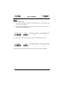
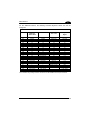
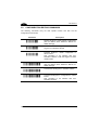
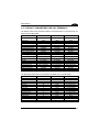
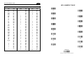
CODE IDENTIFIER TABLE
CODE
2/5 interleaved
2/5 industrial
2/5 normal 5 bars
2/5 matrix 3 bars
EAN 8
EAN 13
UPC A
UPC E
EAN 8 with 2 ADD ON
EAN 8 with 5 ADD ON
EAN 13 with 2 ADD ON
EAN 13 with 5 ADD ON
UPC A with 2 ADD ON
UPC A with 5 ADD ON
UPC E with 2 ADD ON
UPC E with 5 ADD ON
Code 39
Code 39 Full ASCII
CODABAR
ABC CODABAR
Code 128
EAN 128
ISBT 128
Code 93
CIP/39
CIP/HR
Code 32
MSI
Plessey Standard
Plessey Anker
Telepen
Delta IBM
Code 11
Code 16K
Code 49
RSS Expanded Linear and Stacked
RSS Limited
RSS 14 Linear and Stacked
AIM STANDARD
DATALOGIC STANDARD
]Iy
]Xy
]Sy
]Xy
]E4
]E0
]Xy
]Xy
]E5
]E6
]E1
]E2
]Xy
]Xy
]Xy
]Xy
]Ay
]Ay
]Fy
]Xy
]Cy
]Cy
] C4
]Gy
]Xy
]Xy
]Xy
]My
]P0
]P1
]X0
]X0
]Hy
]K0
]Ty
]e0
]e0
]e0
N
P
O
Q
A
B
C
D
J
K
L
M
F
G
H
I
V
W
R
S
T
k
f
U
Y
e
X
Z
a
o
d
c
b
p
q
t
v
u
Custom
59
DATA FORMAT
•
AIM standard identifiers are not defined for all codes: the X identifier is assigned to the
code for which the standard is not defined. The y value depends on the selected options
(check digit tested or not, check digit tx or not, etc.).
•
When customizing the Datalogic Standard code identifiers, 1 or 2 identifier characters can
be defined for each code type. If only 1 identifier character is required, the second
character must be selected as FF (disabled).
•
The code identifier can be singly disabled for any code by simply selecting FF as the first
identifier character.
•
Write in the Custom character identifiers in the table above for your records.
60
Enter Configuration
Ì$+;Î
Exit and Save Configuration
DATA FORMAT
Ì$-?Î
CODE IDENTIFIER
disable
ÌEB0SÎ
Datalogic standard
ÌEB1VÎ
AIM standard
ÌEB2YÎ
custom
ÌEB3\Î
61
Enter Configuration
Exit and Save Configuration
Ì$+;Î
Ì$-?Î
DATA FORMAT
CUSTOM CODE IDENTIFIER
define custom code identifier(s)
ÌEH/Î
Read the above code.
(Code Identifiers default to Datalogic standard, see table on previous page).
Select the code type from the code table in Appendix B for the identifier you want to
change.
You can define 1 or 2 identifier characters for each code type. If only 1 identifier character is
required, the second character must be selected as FF (disabled). Read the hexadecimal
value corresponding to the character(s) you want to define as identifiers for the code
selected in step : valid characters are in the range 00-FD.
Example:
To define Code 39 Code Identifier = @
define custom code identifier(s)
Read
62
ÌEH/Î
Code 39
+
ÌVWÎ
+
40
+
FF
Enter Configuration
Ì$+;Î
Exit and Save Configuration
Ì$-?Î
DATA FORMAT
HEADER
no header
ÌEA00*Î
one character header
ÌEA01.Î
two character header
ÌEA022Î
three character header
ÌEA036Î
four character header
ÌEA04:Î
five character header
ÌEA05>Î
six character header
ÌEA06BÎ
seven character header
ÌEA07FÎ
eight character header
ÌEA08JÎ
After selecting one of the desired Header codes, read the character(s) from the HEX table. Valid characters
are in the range 00-FE.
Example:
four character header
+ 41 + 42 + 43 + 44 = Header ABCD
For more details see par. 5.4.1 and par. 5.4.2.
63
Enter Configuration
Ì$+;Î
Exit and Save Configuration
Ì$-?Î
DATA FORMAT
TERMINATOR
no terminator
ÌEA10-Î
one character terminator
ÌEA111Î
two character terminator
ÌEA125Î
three character terminator
ÌEA139Î
four character terminator
ÌEA14=Î
five character terminator
ÌEA15AÎ
six character terminator
ÌEA16EÎ
seven character terminator
ÌEA17IÎ
eight character terminator
ÌEA18MÎ
After selecting one of the desired Header codes, read the character(s) from the HEX table. Valid characters
are in the range 00-FE.
Example:
two character terminator
+ 0D + 0A = Terminator CR LF
For more details see par. 5.4.1. and par. 5.4.2.
64
Enter Configuration
Ì$+;Î
Exit and Save Configuration
Ì$-?Î
DATA FORMAT
FIELD ADJUSTMENT
disable field adjustment
ÌEF0[Î
Field adjustment allows a number of characters n, to be added to or subtracted from the
barcode read. The adjustment can be different for each enabled code type. To define the field
adjustment:
Read the enable field adjustment code:
enable field adjustment
ÌEF+Î
Select the code type from the Code Identifier Table in Appendix B.
Select the type of adjustment to perform:
right addition
Ì01Î
left addition
Ì12Î
right deletion
Ì23Î
left deletion
Ì34Î
Read a number in the range 01 - 32 from the Hex/Numeric Table to define how many
characters to add or delete:
Conditions:
•
Adjustment is only performed on the barcode data, the Code Identifier and Code Length
Transmission fields are not modified by the field adjustment parameter.
•
If the field setting would subtract more characters than exist in the barcode, the subtraction
will take place only to code length 0.
•
You can set up to a maximum of 10 different field adjustments on the same barcode family
or on different barcode families.
Example: To add 4 characters to the right of Standard Code 39 Codes:
enable field adjustment
Read
ÌEF+Î
Code 39
+
ÌVWÎ
right addition
+
Ì01Î
+
04
65
Enter Configuration
Ì$+;Î
Exit and Save Configuration
DATA FORMAT
Ì$-?Î
FIELD ADJUSTMENT CHARACTER
Read the field adjustment character code:
field adjustment character
ÌEG-Î
Read the hexadecimal value corresponding to the character you want to use for field
adjustment. Valid characters are in the range 00-FE.
Example:
To define the field adjustment character = A:
field adjustment character
Read
+ 41
CODE LENGTH TX
code length not transmitted
ÌEE0YÎ
code length transmitted in variable-digit format
ÌEE1\Î
code length transmitted in fixed 4-digit format
ÌEE2_Î
The code length is transmitted in the message after the Headers and Code Identifier characters.
The code length is calculated after performing any field adjustment operations.
66
Enter Configuration
Ì$+;Î
Exit and Save Configuration
DATA FORMAT
Ì$-?Î
CHARACTER REPLACEMENT
disable character replacement
ÌEO0mÎ
This parameter allows up to three characters to be replaced from the barcode read. These
substitutions are stored in memory. To define each character replacement:
Read one of the following character replacement codes:
first character replacement
ÌEO1pÎ
second character replacement
ÌEO2sÎ
third character replacement
ÌEO3vÎ
From the Code Identifier Table in Appendix B, read the Code Identifier for the desired
code family.
0 = character replacement will be effective for all code families.
From the Hex/Numeric Table read two characters corresponding to the Hex value (00-FE)
which identifies the character to be replaced.
From the Hex/Numeric Table read two characters corresponding to the Hex value (00-FE)
which identifies the new character to replace.
FF = the character to be replaced will be substituted with no character, that is, it will be
removed from the code.
67
Enter Configuration
Exit and Save Configuration
Ì$+;Î
Ì$-?Î
DATA FORMAT
Example:
The following strings define:
1.
First Character Replacement: substitution in Code 39 barcodes of all occurrences of the 0
character with the 1 character.
2.
Second Character Replacement: substitution in Code 39 barcodes of all occurrences of
the A character with the B character.
first character replacement
Code 39
ÌEO1pÎ + ÌVWÎ +
ASCII characters corresponding
to the HEX value for character 0
30
ASCII characters corresponding
to the HEX value for character 1
+
31
For Code 39 codes containing the string "0123", the contents transmitted will be "1123".
second character
replacement
Code 39
ÌEO2sÎ + ÌVWÎ +
ASCII characters corresponding
to the HEX value for character A
41
ASCII characters corresponding
to the HEX value for character B
+
42
For Code 39 codes containing the string "ABCD", the contents transmitted will be "BBCD".
68
Enter Configuration
Ì$+;Î
Exit and Save Configuration
DATA FORMAT
Ì$-?Î
ADDRESS STAMPING (M SERIES ONLY)
disable reader address stamping
ÌRU0ÊÎ
enable reader address stamping
ÌRU1"Î
See par. 5.4.3 for details.
ADDRESS DELIMITER (M SERIES ONLY)
disable reader address delimiter
ÌRV0!Î
enable reader address delimiter and select characters
ÌRV1$Î
Read 2 HEX characters in the range 00-FE.
See par. 5.4.4 for details.
69
POWER SAVE
SCAN RATE
SLEEP STATE/USB SUSPEND
ENTER SLEEP TIMEOUT
STANDBY
1.
Read the Enter Configuration code ONCE, available at the top of each page.
2.
Read configuration codes from the desired groups.
= Read the code and follow the procedure given
= Default value
3.
70
Read the Exit and Save Configuration code ONCE, available at the top of
each page.
Enter Configuration
Ì$+;Î
Exit and Save Configuration
POWER SAVE
Ì$-?Î
SCAN RATE
67 scans per sec.
ÌBT0tÎ
135 scans per sec.
ÌBT1wÎ
270 scans per sec.
ÌBT2zÎ
A lower scan rate reduces power consumption but can lengthen reading response time.
SLEEP STATE/USB SUSPEND
disable
ÌBQ0nÎ
enable
ÌBQ1qÎ
See par. 5.5.1 for details.
For M-Series readers, sleep state is entered immediately after reading a code and is not
configurable.
71
Enter Configuration
Ì$+;Î
Exit and Save Configuration
POWER SAVE
Ì$-?Î
ENTER SLEEP TIMEOUT
enter sleep timeout
ÌBR@Î
Read 2 numbers in the range 00-99:
00 = Enter Sleep state immediately
01-99 = corresponds to a max. 9.9 sec. delay before entering the
Sleep state.
enter sleep timeout = 0.6 sec.
See par. 5.5.2 for details.
STANDBY
disable
ÌBM1iÎ
optimize for reading speed
enable
ÌBM0fÎ
optimize for low power consumption
See par. 5.5.3 for details.
For M-Series readers, standby is always enabled and is not configurable.
72
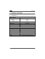
READING PARAMETERS
OPERATING MODE
HAND-HELD OPERATION
STAND OPERATION
HARDWARE TRIGGER MODE
TRIGGER-OFF TIMEOUT
FLASH MODE
READS PER CYCLE
SAFETY TIME
BEEPER INTENSITY
BEEPER TONE
BEEPER TYPE
BEEPER LENGTH
PDF DECODING RECOGNITION
INTENSITY
GOOD READ SPOT DURATION
1.
Read the Enter Configuration code ONCE, available at the top of each page.
2.
Read configuration codes from the desired groups.
= Read the code and follow the procedure given
= Default value
3.
Read the Exit and Save Configuration code ONCE, available at the top of
each page.
73
Enter Configuration
Ì$+;Î
Exit and Save Configuration
READING PARAMETERS
Ì$-?Î
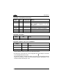
OPERATING MODE
You can pre-configure both Hand-Held and Stand operating modes, and with the codes below,
you can switch between them. See par. 5.6.1 for details. Stand operation is not advised for MSeries readers since it constantly consumes battery power.
hand-held operation
ÌBP0lÎ
automatic
ÌBP2rÎ
stand operation
ÌBP1oÎ
HAND-HELD OPERATION
hardware trigger
ÌBK1eÎ
software trigger
ÌBK0bÎ
* always on
ÌBK3kÎ
* not available for M-Series readers
automatic
ÌBK2hÎ
hardware trigger ready
ÌBK4nÎ
74
Enter Configuration
Ì$+;Î
Exit and Save Configuration
READING PARAMETERS
Ì$-?Î
STAND OPERATION
hardware trigger
ÌBU3ÃÎ
software trigger
ÌBU1yÎ
* always on
ÌBU2|Î
* not available for M-Series readers
automatic
ÌBU0vÎ
HARDWARE TRIGGER MODE
trigger active level
ÌBA0NÎ
trigger active pulse
ÌBA1QÎ
See par. 5.6.2 for details
TRIGGER-OFF TIMEOUT
trigger-off timeout
ÌBD$Î
Read 2 numbers in the range 00-99:
00 = disables the trigger-off timeout
01-99 = corresponds to a max. 99-sec. delay after the trigger
press to allow the reader to turn off automatically.
trigger-off timeout disabled
See par. 5.6.3 for details.
75
Enter Configuration
Ì$+;Î
Exit and Save Configuration
READING PARAMETERS
FLASH MODE
"FLASH" ON duration
ÌBB0PÎ
"FLASH" OFF duration
ÌBB1SÎ
Read 2 numbers in the range 01-99:
01 to 99 = from .1 to 9.9 seconds.
Flash-ON = 1 sec. Flash-OFF = 0.6 sec
READS PER CYCLE
one read per cycle
ÌBC0RÎ
multiple reads per cycle
ÌBC1UÎ
See par. 5.6.4 for details.
76
Ì$-?Î
Enter Configuration
Ì$+;Î
Exit and Save Configuration
READING PARAMETERS
Ì$-?Î
SAFETY TIME
safety time
ÌBE&Î
Limits same code consecutive reading.
Read 2 numbers in the range 00-99:
00 = no same code consecutive reading until reader is
removed (no decoding) for at least 400 ms.
01-99 = timeout from .1 to 9.9 seconds before a consecutive read
on same code.
safety time = 0.5 sec
See par. 5.6.5 for details.
BEEPER INTENSITY
* very low intensity
ÌBG0ZÎ
low intensity
ÌBG1]Î
medium intensity
ÌBG2`Î
high intensity
ÌBG3cÎ
*
This sets the beeper OFF for data entry, while for all other beeper signals it has the
meaning “very low intensity”. The Beeper Intensity parameter is effective for all operating
conditions described in par. 6.5.
77
Enter Configuration
Ì$+;Î
Exit and Save Configuration
READING PARAMETERS
Ì$-?Î
BEEPER TONE
tone 1
ÌBH0\Î
tone 2
ÌBH1_Î
tone 3
ÌBH2bÎ
tone 4
ÌBH3eÎ
BEEPER TYPE
monotone
ÌBJ0`Î
bitonal
ÌBJ1cÎ
BEEPER LENGTH
long
ÌBI0^Î
short
ÌBI1aÎ
78
Enter Configuration
Exit and Save Configuration
Ì$+;Î
Ì$-?Î
READING PARAMETERS
PDF DECODING RECOGNITION INTENSITY
low
ÌBW0zÎ
high
ÌBW1}Î
GOOD READ SPOT DURATION
disable
ÌBV0xÎ
short
ÌBV1{Î
medium
ÌBV2~Î
long
ÌBV3ÅÎ
79
DECODING PARAMETERS
INK SPREAD
OVERFLOW CONTROL
INTERDIGIT CONTROL
DECODING SAFETY
PUZZLE SOLVER™
Before changing these parameter values read the descriptions in
par. 5.7.
CAUTION
1.
2.
3.
80
Read the Enter Configuration code ONCE, available at the top of each page.
Read configuration codes from the desired groups.
= Default value
Read the Exit and Save Configuration code ONCE, available at the top of
each page.
Enter Configuration
Ì$+;Î
Exit and Save Configuration
DECODING PARAMETERS
Ì$-?Î
INK SPREAD
disable
ÌAX0{Î
enable
ÌAX1~Î
See par. 5.7.1 for details.
OVERFLOW CONTROL
disable
ÌAW1|Î
enable
ÌAW0yÎ
See par. 5.7.2 for details.
81
Enter Configuration
Exit and Save Configuration
Ì$+;Î
Ì$-?Î
DECODING PARAMETERS
INTERDIGIT CONTROL
disable
ÌAV0wÎ
enable
ÌAV1zÎ
See par. 5.7.3 for details.
DECODING SAFETY
one read
ÌED0WÎ
(decoding safety disabled)
two reads
ÌED1ZÎ
three reads
ÌED2]Î
four reads
ÌED3`Î
Required number of good reads before accepting code.
82
Enter Configuration
Exit and Save Configuration
Ì$+;Î
DECODING PARAMETERS
Ì$-?Î
PUZZLE SOLVER™
disable
ÌAU0uÎ
enable
ÌAU1xÎ
In the case of damaged or poorly printed codes, this parameter allows reading multiple parts of
the single code to reconstruct it.
To read codes using this technology, simply move the illuminated bar over the code so that
each line of the code is scanned. During this process a series of brief “ticks” indicates that
reading is proceeding correctly.
Conditions:
•
This parameter is only valid for the following codes:
EAN 8
without Add-on
EAN 13
without Add-on
Code 128
Code 39
UPC A
without Add-on
•
For Code 39, Check digit control without transmission is forced.
•
PuzzleSolver™ is disabled when code ISBT 128 is enabled.
83
CODE SELECTION
EAN/UPC FAMILY
2/5 FAMILY
CODE 39 FAMILY
CODE 128 FAMILY
CODABAR FAMILY
CODE 93
MSI
PLESSEY
TELEPEN
DELTA IBM
CODE 11
CODE 16K
CODE 49
PDF417
PDF READERS ONLY
RSS CODES
1.
Read the Enter Configuration code ONCE, available at the top of each page.
2.
Read configuration codes from the desired groups.
= Read the code and follow the procedure given
= Default value
3.
84
Read the Exit and Save Configuration code ONCE, available at the top of
each page.
Enter Configuration
Exit and Save Configuration
Ì$+;Î
CODE SELECTION
Ì$-?Î
DISABLE ALL CODE FAMILIES
ÌAZ0ÃÎ
The reader allows up to 5 code selections. This does not limit the
number of CODES enabled to 5, as it depends on the code family.
NOTE
SINGLE
SELECTIONS =
•
ONE combination code from the EAN family
•
ONE code from the 2/5 family
Example
5 code selections:
1. 2/5 Interleaved
2. 2/5 Industrial
3. Code 128 + EAN 128
4. Code 39 Full ASCII + Code 32
5. UPC A/UPC E
In this section all SINGLE code selections are underlined and in bold.
85
Enter Configuration
Exit and Save Configuration
Ì$+;Î
CODE SELECTION
Ì$-?Î
EAN/UPC FAMILY
disable the family
ÌAA0MÎ
Read the desired family code
Note:
Since the EAN/UPC without ADD ON code selection is enabled by default, to correctly enable
another selection, first disable the family.
EAN 8/EAN 13/UPC A/UPC E with and without ADD ON
ÌAA8eÎ
WITHOUT ADD ON
EAN 8/EAN 13/UPC A/UPC E
ÌAA1PÎ
EAN 8/EAN 13
ÌAA3VÎ
UPC A/UPC E
ÌAA4YÎ
86
Enter Configuration
Exit and Save Configuration
Ì$+;Î
Ì$-?Î
CODE SELECTION
WITH ADD ON 2 AND 5
EAN 8/EAN 13/UPC A/UPC E
ÌAA5\Î
EAN 8/EAN 13
ÌAA6_Î
UPC A/UPC E
ÌAA7bÎ
WITH ADD ON 2 ONLY
EAN 8/EAN 13
ÌAAK7Î
UPC A/UPC E
ÌAAM=Î
WITH ADD ON 5 ONLY
EAN 8/EAN 13
ÌAAL:Î
UPC A/UPC E
ÌAAN@Î
87
Enter Configuration
Exit and Save Configuration
Ì$+;Î
Ì$-?Î
CODE SELECTION
EAN/UPC CHECK DIGIT TX SELECTIONS
For each code type in this family you can choose to transmit the check digit or not
CHECK DIGIT TRANSMISSION
NO CHECK DIGIT
TRANSMISSION
EAN 8
ÌAAG1oÎ
EAN 8
ÌAAG0kÎ
EAN 13
ÌAAH1rÎ
EAN 13
ÌAAH0nÎ
UPC A
ÌAAI1uÎ
UPC A
ÌAAI0qÎ
UPC E
ÌAAJ1xÎ
UPC E
ÌAAJ0tÎ
88
Enter Configuration
Ì$+;Î
Exit and Save Configuration
CODE SELECTION
Ì$-?Î
CONVERSION OPTIONS
UPC E to UPC A conversion
ÌAAAÄÎ
UPC E to EAN 13 conversion
ÌAABÇÎ
UPC A to EAN 13 conversion
ÌAACÊÎ
EAN 8 to EAN 13 conversion
ÌAAD"Î
Enable only ISBN conversion
ÌAP1nÎ
Enable only ISSN conversion
ÌAP2qÎ
Enable both ISBN and ISSN conversion
ÌAP3tÎ
Disable both ISBN and ISSN conversion
ÌAP0kÎ
89
Enter Configuration
Ì$+;Î
Exit and Save Configuration
CODE SELECTION
Ì$-?Î
2/5 FAMILY
disable the family
ÌAC0QÎ
Read the desired family code
Read a check digit selection
Interleaved 2/5
ÌAC1TÎ
CHECK DIGIT TABLE
no check digit control
Ì12Î
Normal 2/5 (5 Bars)
ÌAC2WÎ
check digit control and transmission
Ì23Î
Industrial 2/5 (IATA)
ÌAC3ZÎ
check digit control without transmission
Ì34Î
Matrix 2/5 (3 Bars)
ÌAC4]Î
−
−
The pharmaceutical code below is part of
the 2/5 family but has no check digit or
code length selections.
Code CIP/HR
ÌAC5`Î
French pharmaceutical code
90
Read 4 numbers for the code length
where:
First 2 digits = minimum code
length.
Second 2 digits = maximum code
length.
The maximum code length is 99
characters.
The minimum code length must always
be less than or equal to the maximum.
Examples:
0199 = variable from 1 to 99 digits in
the code.
1010 = 10 digit code length only.
Enter Configuration
Ì$+;Î
Exit and Save Configuration
CODE SELECTION
Ì$-?Î
CODE 39 FAMILY
disables the family
ÌAB0OÎ
Read the desired family code
Read a check digit selection
CHECK DIGIT TABLE
Standard Code 39
no check digit control
ÌAB1RÎ
Ì12Î
Full ASCII Code 39
ÌAB2UÎ
check digit control
and transmission
Ì23Î
check digit control
without transmission
Ì34Î
91
Enter Configuration
Ì$+;Î
Exit and Save Configuration
CODE SELECTION
Ì$-?Î
The pharmaceutical codes below are part of the Code 39 family but have no check digit
selections.
Code CIP39
ÌAB3XÎ
French pharmaceutical code
Code 32
ÌAB4[Î
Italian pharmaceutical code
CODE LENGTH (optional)
The code length selection is valid for the entire Code 39 family
Read the code + 4 numbers for the code length where:
First 2 digits = minimum code length.
Second 2 digits = maximum code length.
set code length
ÌAB*=Î
The maximum code length is 99 characters.
The minimum code length must always be less than or equal to the maximum.
Examples: 0199 = variable from 1 to 99 digits in the code. 1010 = 10 digit code length only.
92
Enter Configuration
Ì$+;Î
Exit and Save Configuration
CODE SELECTION
Ì$-?Î
CODE 128 FAMILY
disables the family
ÌAI0]Î
Read the desired family code
Code 128
ÌAI11=Î
control without transmission
of check digit
EAN 128
ÌAI21@Î
control without transmission
of check digit
Transmit GS Before Code
Code EAN 128 uses the ASCII <GS> character to separate a variable length code field from the
next code field. This character can also be transmitted before the code.
disable
ÌEQ0qÎ
enable
ÌEQ1tÎ
If the <GS> character has been modified in the Character Replacement parameter, the new
character is affected by this command.
93
Enter Configuration
Ì$+;Î
Exit and Save Configuration
CODE SELECTION
Ì$-?Î
ISBT 128
ÌAI31CÎ
Enabling ISBT 128 automatically disables Puzzle Solver™.
CODE LENGTH (optional)
The code length selection is valid for the entire Code 128 family.
Read the code + 4 numbers for the code length where:
set code length
ÌAILJÎ
First 2 digits = minimum code length
Second 2 digits = maximum code length
The maximum code length is 99 characters. The minimum code length must always be less
than or equal to the maximum.
Examples:
0199 = variable from 1 to 99 digits in the code. 1010= 10 digit code length only.
The length is calculated on the output string.
CODE 93
disables the code
ÌAK0aÎ
Code 93
ÌAK1dÎ
control without transmission
of check digit
94
Enter Configuration
Exit and Save Configuration
Ì$+;Î
Ì$-?Î
CODE SELECTION
CODABAR FAMILY
disable the family
ÌAD0SÎ
Read the desired equality control code
Read a start/stop transmission
selection
START/STOP CHARACTER
TRANSMISSION
Standard Codabar
ÌAD113Î
no start/stop character equality control
no transmission
Ì12Î
Standard Codabar
ÌAD127Î
start/stop character equality control
transmission
Ì23Î
The Codabar ABC code below uses a fixed start/stop character transmission selection.
Codabar ABC
ÌAD212)Î
no start/stop character equality control but transmission.
95
Enter Configuration
Exit and Save Configuration
Ì$+;Î
Ì$-?Î
CODE SELECTION
Codabar ABC Forced Concatenation
enable Codabar ABC with forced concatenation
ÌAD2321Î
non start/stop character equality control but transmission
CODE LENGTH (optional)
The code length selection is valid for the entire Codabar family
set code length
Read the code + 4 numbers for the code length where:
First 2 digits = minimum code length.
Second 2 digits = maximum code length.
ÌAD*AÎ
The maximum code length is 99 characters.
The minimum code length must always be less than or equal to the maximum.
Examples: 0199 = variable from 1 to 99 digits in the code. 1010 = 10 digit code length only.
START/STOP CHARACTER CASE IN TRANSMISSION
The start/stop character case selections below are valid for the entire Codabar family:
transmit start/stop characters in lower case
ÌADA0_Î
transmit start/stop characters in upper case
ÌADA1cÎ
96
Enter Configuration
Ì$+;Î
Exit and Save Configuration
CODE SELECTION
Ì$-?Î
MSI
disable the family
ÌAE0UÎ
Enable the code by selecting one of the check digit selections.
no check digit control
ÌAE1XÎ
MOD10 check digit control
no check digit transmission
ÌAE2[Î
MOD10 check digit control
check digit transmission
ÌAE3^Î
MOD11 - MOD10 check digit control
no check digit transmission
ÌAE4aÎ
MOD11 - MOD10 check digit control
check digit transmission
ÌAE5dÎ
MOD10 - MOD10 check digit control
no check digit transmission
ÌAE6gÎ
MOD10 - MOD10 check digit control
check digit transmission
ÌAE7jÎ
97
Enter Configuration
Ì$+;Î
Exit and Save Configuration
CODE SELECTION
Ì$-?Î
PLESSEY
disable the family
ÌAF0WÎ
Enable the code by selecting one of the check digit selections.
Standard Plessey
no check digit control
ÌAF117Î
check digit control
check digit transmitted
ÌAF12;Î
check digit control
check digit not transmitted
ÌAF13?Î
Anker Plessey
no check digit control
ÌAF21:Î
check digit control
check digit transmitted
ÌAF22>Î
check digit control
check digit not transmitted
ÌAF23BÎ
98
Enter Configuration
Ì$+;Î
Exit and Save Configuration
CODE SELECTION
Ì$-?Î
TELEPEN
disable the family
ÌAL0cÎ
Enable the code by selecting one of the check digit selections.
Numeric Telepen
no check digit control
ÌAL11CÎ
check digit control
check digit transmitted
ÌAL12GÎ
check digit control
check digit not transmitted
ÌAL13KÎ
Alphanumeric Telepen
no check digit control
ÌAL21FÎ
check digit control
check digit transmitted
ÌAL22JÎ
check digit control
check digit not transmitted
ÌAL23NÎ
99
Enter Configuration
Ì$+;Î
Exit and Save Configuration
CODE SELECTION
DELTA IBM
disable the family
ÌAH0[Î
Enable the code by selecting one of the check digit selections.
no check digit control
ÌAH1^Î
Type 1 check digit control
ÌAH2aÎ
Type 2 check digit control
ÌAH3dÎ
100
Ì$-?Î
Enter Configuration
Ì$+;Î
Exit and Save Configuration
CODE SELECTION
Ì$-?Î
CODE 11
disable the family
ÌAG0YÎ
Enable the code by selecting one of the check digit selections.
no check digit control
ÌAG1\Î
Type C check digit control
check digit transmitted
ÌAG21<Î
Type C check digit control
check digit not transmitted
ÌAG22@Î
Type K check digit control
check digit transmitted
ÌAG31?Î
Type K check digit control
check digit not transmitted
ÌAG32CÎ
Type C and Type K
check digit control
check digits transmitted
ÌAG41BÎ
Type C and Type K
check digit control
check digits not transmitted
ÌAG42FÎ
101
Enter Configuration
Ì$+;Î
Exit and Save Configuration
CODE SELECTION
Ì$-?Î
CODE 16K
disable the code
ÌAJ0_Î
Code 16K
ÌAJ1bÎ
To read stacked codes, simply move the reader over the code so that each line of the code is
scanned. During this process a series of brief “ticks” indicates that reading is proceeding
correctly.
CODE 49
disable the code
ÌAM0eÎ
Code 49
ÌAM1hÎ
To read stacked codes, simply move the reader over the code so that each line of the code is
scanned. During this process a series of brief “ticks” indicates that reading is proceeding
correctly.
102
Enter Configuration
Ì$+;Î
Exit and Save Configuration
CODE SELECTION
Ì$-?Î
PDF417
Only PDF417 readers
disable the code
ÌAR0oÎ
PDF417
ÌAR1rÎ
To read stacked codes, simply move the reader over the code so that each line of the code is
scanned. During this process a series of brief “ticks” indicates that reading is proceeding
correctly.
103
Enter Configuration
Ì$+;Î
Exit and Save Configuration
CODE SELECTION
Ì$-?Î
RSS CODES
disable the family
ÌAQ0mÎ
DISABLE CODE
ENABLE CODE
disable RSS Expanded Linear and Stacked
ÌAQ10IÎ
enable RSS Expanded Linear and Stacked
ÌAQ11MÎ
disable RSS Limited
ÌAQ20LÎ
enable RSS Limited
ÌAQ21PÎ
disable RSS 14 Linear and Stacked
ÌAQ30OÎ
enable RSS 14 Linear and Stacked
ÌAQ31SÎ
To read stacked codes, simply move the reader over the code so that each line of the code is
scanned. During this process a series of brief “ticks” indicates that reading is proceeding
correctly.
104
ADVANCED FORMATTING
NOT FOR PEN INTERFACES
CONCATENATION
ADVANCED FORMATTING
Please follow the setup procedure carefully for these parameters.
NOTE
The Advanced Formatting parameters may not be compatible with the
IBM USB POS/IBM 46xx interface selection.
NOTE
1.
2.
Read the Enter Configuration code ONCE, available at the top of page .
Read configuration codes precisely following the numbered procedure
given.
= Read the code and follow the procedure given
= Default value
3.
Read the Exit and Save Configuration code ONCE, available at the top of
page.
105
Enter Configuration
Ì$+;Î
Exit and Save Configuration
ADVANCED FORMATTING
Ì$-?Î
CONCATENATION
disable
ÌEI0aÎ
enable
ÌEI1dÎ
Permits the concatenation of two codes defined by code type and length. It is possible to set a
timeout for the second code reading and to define code transmission if the timeout expires.
The order of transmission is CODE 1-CODE 2.
Define Concatenation
1
Code 1
code ID
ÌEK0eÎ
Read the code type from the Code Identifier Table beginning in Appendix B.
code length
ÌEL0gÎ
Read a number in the range 01-99 from the Hex/Numeric Table.
106
Exit and Save Configuration
ADVANCED FORMATTING
2
Ì$-?Î
Code 2
code ID
ÌEK1hÎ
Read the code type from the Code Identifier Table beginning in Appendix B.
code length
ÌEL1jÎ
Read a number in the range 01-99 from the Hex/Numeric Table.
3
Concatenation Result Code ID
use code 1 ID
ÌEN0kÎ
use code 2 ID
ÌEN1nÎ
Since you can concatenate codes from different families, you must select the Code ID character
of the resulting code. The Code ID character will be sent in the output message only if it is
enabled according to the Code Identifier selection (Datalogic, AIM, or Custom).
4
Concatenation Timeout
timeout
ÌEJ3Î
Read two numbers in the range 00 to 99
00= no timeout
01-99 = timeout from 1 to 99 seconds
Define the timeout, which determines the valid waiting period between the two codes, in order to
accept concatenation. If the timeout expires, the resulting action will be based on the following
selection.
107
Exit and Save Configuration
ADVANCED FORMATTING
5
Transmission after Timeout
no code transmitted
after timeout
ÌEM0iÎ
only code 1 transmitted
(if read) after timeout
ÌEM1lÎ
only code 2 transmitted
(if read) after timeout
ÌEM2oÎ
either code 1 or code 2 transmitted
after timeout
ÌEM3rÎ
108
Ì$-?Î
ADVANCED FORMATTING
ADVANCED FORMATTING
Advanced formatting has been designed to offer you complete flexibility in changing the format
of barcode data before transmitting it to the host system. This formatting will be performed
when the barcode data meets certain criteria which you will define in the following procedure.
Up to 4 advanced code management formats can be defined and saved in memory. For each
format you must complete the entire configuration procedure:
Read the Enter
Configuration Command
Step 1
Begin Format Definition
1, 2, 3, or 4
Steps 2 - 4
Define Match Code Conditions
Step 5
Divide Code into Fields
Step 6
Define Code Fields
Steps 7 - 8
Add up to 2 Additional Fields
Step 9
Define Field Transmission
Step 10
Apply or Not
Standard Message Formatting
Step 11
End Format Definition
1, 2, 3, or 4
YES
Define another?
NO
Enable Advanced Formats
1, 2, 3, 4
Define No Match Result
Read the Exit and Save
Configuration Command
109
Enter Configuration
Ì$+;Î
1
Exit and Save Configuration
ADVANCED FORMATTING
Ì$-?Î
Begin Format Definition
begin Format 1 definition
ÌHA0TÎ
begin Format 2 definition
ÌHA1WÎ
begin Format 3 definition
ÌHA2ZÎ
begin Format 4 definition
ÌHA3]Î
2
Match Code Type
match code type
ÌHB&Î
Read the above code + the code type to match from the Code Identifier Table in Appendix B.
OR
any code type
ÌHB0VÎ
3
Match Code Length
match code length
ÌHC(Î
Read the above code + two numbers in the range 01 to 99 for the exact code length.
OR
any code length
ÌHC001Î
110
Exit and Save Configuration
ADVANCED FORMATTING
Ì$-?Î
Match with Predefined Characters
4
no match
ÌHD0HE00ÄÎ
OR
match with 1 character
ÌHD1]Î
match with a 2-character string
ÌHD2`Î
match with a 3-character string
ÌHD3cÎ
match with a 4-character string
ÌHD4fÎ
After selecting the predefined match code, read the character(s) from the HEX table. Range
of characters = 01-FE.
Example:
Match code with the 2-character predefined string = "@@".
Match with a 2-character string
Read
AND
+ 40 + 40
position of first character in predefined string
ÌHE,Î
Read the above code + two numbers in the range 01 to 99 representing the character
position in the code where the first character of the predefined string must be found.
Read 00 if the match string can be found in any character position.
111
Exit and Save Configuration
ADVANCED FORMATTING
Ì$-?Î
Divide Code into Fields
5
divide code into fields
ÌHF.Î
Read one number in the range 1 to 5 to divide the code into fields.
6
Define Code Fields
define code fields
Each code field length can be set by either:
a) defining a field separator character to be found in the code itself. In this case you can
choose to discard the code separator character or include it as the last character of the
field.
OR BY
b) specifying a specific character length up to the maximum of 99 characters.
OR BY
c) selecting the last field as variable length (if any).
You must define the same number of fields as selected in step 5, including fields that will
not be transmitted.
112
Exit and Save Configuration
Ì$-?Î
ADVANCED FORMATTING
DEFINE FIELD 1 BY:
EITHER
field separator
ÌHG0`Î
a)
Read the field separator character from the HEX table. Range of characters = 01-FE.
discard separator
include separator
Ì01Î
Ì12Î
OR
field length
ÌHG1cÎ
b)
Read two numbers in the range 01 to 99 to define the field length.
OR
this is the last field (variable length)
ÌHG2fÎ
c)
AND
Field 1 Terminators
no field terminators
ÌHH0bÎ
1 field terminator
2 field terminators
ÌHH1eÎ
ÌHH2hÎ
Read the field terminator character(s) from the HEX table.
Valid range of characters for all readers = 01-FE.
For readers using Wedge interface, all values from 9C to FE send the Space character.
113
Exit and Save Configuration
Ì$-?Î
ADVANCED FORMATTING
DEFINE FIELD 2 BY:
EITHER
field separator
ÌHG0`Î
a)
Read the field separator character from the HEX table. Range of characters = 01-FE.
discard separator
include separator
Ì01Î
Ì12Î
OR
field length
ÌHG1cÎ
b)
Read two numbers in the range 01 to 99 to define the field length.
OR
this is the last field (variable length)
ÌHG2fÎ
c)
AND
Field 2 Terminators
no field terminators
ÌHH0bÎ
1 field terminator
2 field terminators
ÌHH1eÎ
ÌHH2hÎ
Read the field terminator character(s) from the HEX table.
Valid range of characters for all readers = 01-FE.
For readers using Wedge interface, all values from 9C to FE send the Space character.
114
Exit and Save Configuration
Ì$-?Î
ADVANCED FORMATTING
DEFINE FIELD 3 BY:
EITHER
field separator
ÌHG0`Î
a)
Read the field separator character from the HEX table. Range of characters = 01-FE.
discard separator
include separator
Ì01Î
Ì12Î
OR
field length
ÌHG1cÎ
b)
Read two numbers in the range 01 to 99 to define the field length.
OR
this is the last field (variable length)
ÌHG2fÎ
c)
AND
Field 3 Terminators
no field terminators
ÌHH0bÎ
1 field terminator
2 field terminators
ÌHH1eÎ
ÌHH2hÎ
Read the field terminator character(s) from the HEX table.
Valid range of characters for all readers = 01-FE.
For readers using Wedge interface, all values from 9C to FE send the Space character.
115
Exit and Save Configuration
Ì$-?Î
ADVANCED FORMATTING
DEFINE FIELD 4 BY:
EITHER
field separator
ÌHG0`Î
a)
Read the field separator character from the HEX table. Range of characters = 01-FE.
discard separator
include separator
Ì01Î
Ì12Î
OR
field length
ÌHG1cÎ
b)
Read two numbers in the range 01 to 99 to define the field length.
OR
this is the last field (variable length)
ÌHG2fÎ
c)
AND
Field 4 Terminators
no field terminators
ÌHH0bÎ
1 field terminator
2 field terminators
ÌHH1eÎ
ÌHH2hÎ
Read the field terminator character(s) from the HEX table.
Valid range of characters for all readers = 01-FE.
For readers using Wedge interface, all values from 9C to FE send the Space character.
116
Exit and Save Configuration
Ì$-?Î
ADVANCED FORMATTING
DEFINE FIELD 5 BY:
EITHER
field separator
ÌHG0`Î
a)
Read the field separator character from the HEX table. Range of characters = 01-FE.
discard separator
include separator
Ì01Î
Ì12Î
OR
field length
ÌHG1cÎ
b)
Read two numbers in the range 01 to 99 to define the field length.
OR
this is the last field (variable length)
ÌHG2fÎ
c)
AND
Field 5 Terminators
no field terminators
ÌHH0bÎ
1 field terminator
2 field terminators
ÌHH1eÎ
ÌHH2hÎ
Read the field terminator character(s) from the HEX table.
Valid range of characters for all readers = 01-FE.
For readers using Wedge interface, all values from 9C to FE send the Space character.
117
Exit and Save Configuration
ADVANCED FORMATTING
7
Ì$-?Î
First Additional Fixed Field
no fixed field
ÌHI0dÎ
1 character fixed field
ÌHI1gÎ
2 character fixed field
ÌHI2jÎ
3 character fixed field
ÌHI3mÎ
4 character fixed field
ÌHI4pÎ
5 character fixed field
ÌHI5sÎ
6 character fixed field
ÌHI6vÎ
After selecting one of the Additional Fixed Field codes, read the corresponding character(s)
from the HEX table. Range of characters = 01-FE. For readers using Wedge interface, all values
from 9C to FE send the Space character.
Example:
4 Character Fixed Field
+ 4D + 41 + 49 + 4E =
118
MAIN
Exit and Save Configuration
ADVANCED FORMATTING
8
Ì$-?Î
Second Additional Fixed Field
no fixed field
ÌHJ0fÎ
1 character fixed field
ÌHJ1iÎ
2 character fixed field
ÌHJ2lÎ
3 character fixed field
ÌHJ3oÎ
4 character fixed field
ÌHJ4rÎ
5 character fixed field
ÌHJ5uÎ
6 character fixed field
ÌHJ6xÎ
After selecting one of the Additional Fixed Field codes, read the corresponding character(s)
from the HEX table. Range of characters = 01-FE. For readers using Wedge interface, all values
from 9C to FE send the Space character.
Example:
3 Character Fixed Field
+ 53 + 45 + 54 =
SET
119
Exit and Save Configuration
ADVANCED FORMATTING
Ì$-?Î
Field Transmission
9
number of fields to transmit
ÌHK8Î
Read one number in the range 1 to 7 for the number of fields to transmit. Include only fields to
be transmitted.
Field Order Transmission
Read the codes corresponding to the fields to transmit in the order in which they are to be
transmitted. A field can be transmitted more than once. See example.
field 1
Ì12Î
field 2
Ì23Î
field 3
Ì34Î
field 4
Ì45Î
field 5
Ì56Î
additional field 1
Ì67Î
additional field 2
Ì78Î
Example:
The barcode is divided into 3 defined fields plus 1 additional fixed field.
Transmit in the order: Field 2, Additional Field 1, Field 1, Field 2.
Number of Fields
to Transmit
Field 2
+4+
120
Additional Field 1
+
Field 1
+
Field 2
+
Exit and Save Configuration
ADVANCED FORMATTING
10
Ì$-?Î
Standard Formatting
do not apply standard formatting
ÌHL0jÎ
apply standard formatting
ÌHL1mÎ
After performing Advanced Formatting on the barcode read, Standard Formatting (Headers,
Code Length, Code ID, Terminators) can be applied to the message to be transmitted.
11
End Format Definition
end Format 1 definition
ÌHM0lÎ
end Format 2 definition
ÌHM1oÎ
end Format 3 definition
ÌHM2rÎ
end Format 4 definition
ÌHM3uÎ
121
Enter Configuration
Ì$+;Î
Exit and Save Configuration
ADVANCED FORMATTING
Ì$-?Î
Enable Advanced Format
no Advanced Formats enabled
ÌHN0nÎ
Advanced Format 1
enable
ÌHN11NÎ
disable
ÌHN10JÎ
Advanced Format 2
enable
ÌHN21QÎ
disable
ÌHN20MÎ
Advanced Format 3
enable
ÌHN31TÎ
disable
ÌHN30PÎ
Advanced Format 4
enable
ÌHN41WÎ
disable
ÌHN40SÎ
122
Enter Configuration
Ì$+;Î
Exit and Save Configuration
ADVANCED FORMATTING
Ì$-?Î
No Match Result
clear data - no transmission
ÌHO0pÎ
transmit data using standard format
ÌHO1sÎ
This selection determines the action to be taken when codes read do not conform to the
advanced format requisites (no match).
•
Codes not matching can be ignored, cleared from memory and not transmitted.
•
Codes not matching can be transmitted using the Standard formatting (Headers, Code
Length, Code ID, Terminators).
123
RADIO PARAMETERS
Gryphon™ M Series Readers only
RADIO PROTOCOL TIMEOUT
POWER-OFF TIMEOUT
BEEPER CONTROL FOR RADIO
RESPONSE
BATTERY TYPE
SINGLE STORE
1.
Read the Enter Configuration code ONCE, available at the top of each page.
2.
Read configuration codes from the desired groups.
= Read the code and follow the procedure given
3.
124
Read the Exit and Save Configuration code ONCE, available at the top of
each page.
Enter Configuration
Exit and Save Configuration
Ì$+;Î
RADIO PARAMETERS
Ì$-?Î
RADIO PROTOCOL TIMEOUT
radio protocol timeout
ÌRH<Î
Read a number from the table where:
02-19 =
timeout from 2 to 19 seconds
2 seconds
See par. 5.8.1 for details.
POWER-OFF TIMEOUT
power-off timeout
ÌRPLÎ
Read 2 numbers in the range 00-99:
00 =
01-99 =
Power-off disabled; reader always ready
corresponds to a max. 99 hour delay before power-off.
power-off after 4 hours.
See par. 5.8.2 for details.
125
Enter Configuration
Exit and Save Configuration
Ì$+;Î
Ì$-?Î
RADIO PARAMETERS
BEEPER CONTROL FOR RADIO RESPONSE
normal
ÌBF0XÎ
only good decode
ÌBF1[Î
only good reception
ÌBF2^Î
off
ÌBF3aÎ
See par. 5.8.3 for details.
BATTERY TYPE
OM-GRYPHON™ CRADLE ONLY
NiMh/NiCD
ÌRB1cÎ
alkaline
ÌRB0`Î
126
Enter Configuration
Ì$+;Î
Exit and Save Configuration
RADIO PARAMETERS
Ì$-?Î
SINGLE STORE
disable
ÌRO0zÎ
one attempt
ÌRO1}Î
two attempts
ÌRO2ÄÎ
three attempts
ÌRO3ÇÎ
four attempts
ÌRO4ÊÎ
five attempts
ÌRO5"Î
six attempts
ÌRO6%Î
seven attempts
ÌRO7(Î
eight attempts
ÌRO8+Î
nine attempts
ÌRO9.Î
See par. 5.8.4 for details
127
GRYPHON™
5
5
REFERENCES
5.1
5.1.1
RS232 PARAMETERS
Handshaking
Hardware handshaking: (RTS/CTS)
The RTS line is activated by the decoder before transmitting a character.
Transmission is possible only if the CTS line (controlled by the Host) is active.
Signals at
EIA levels
RTS
TX
Transmitted data
Transmitted data
Host busy
CTS
RTS/CTS handshaking
Software handshaking: (XON/XOFF)
During transmission, if the Host sends the XOFF character (13 Hex), the decoder
interrupts the transmission with a maximum delay of one character and only resumes
when the XON character (11 Hex) is received.
Transmitted data
Transmitted data
TX
RX
XOFF
Host busy
XON
Host ready
XON/XOFF handshaking
128
REFERENCES
5.1.2
5
ACK/NACK Protocol
GRYPHON™ D Series Readers
This parameter sets a transmission protocol in which the Host responds to the reader
after every code transmitted. The Host sends an ACK character (06 HEX) in the case
of good reception or the NACK character (15 HEX) requesting re-transmission, in the
case of bad reception.
data
Gryphon™ D
cable
Host
ACK or NACK
ACK/NACK enabled
If the reader does not receive an ACK or NACK, transmission is ended after the RX
Timeout (see par. 5.1.4).
Selection of the ACK/NACK protocol temporarily disables FIFO buffering see
par. 5.1.3.
GRYPHON™ M Series Readers
The transmission protocol takes place between reader, cradle and Host. The reader
passes its data (code read) to the cradle which sends it to the Host.
In the following descriptions the completed transmission is indicated by the Beeper
Control for Radio Response parameter with its default setting to Normal, see par.
5.8.3.
When ACK/NACK is disabled, there is no control from cradle to Host transmission,
the reader responds with the good reception tone.
data
data
OM-GRYPHON™
GRYPHON™ M
cable
Host
good RX
beep
ACK/NACK disabled
129
GRYPHON™
5
data
data
cable
GRYPHON™ M
good RX
beep
OM-GRYPHON™
NACK
Host
data
ACK
ACK/NACK enabled
When ACK/NACK is enabled, the Host sends an ACK character (06 HEX) in the case
of good reception or the NACK character (15 HEX) requesting re-transmission, in the
case of bad reception. Only after the ACK character is received by the
OM-Gryphon™ does the reader respond with the good reception tone.
If the reader does not receive an ACK or NACK, transmission is ended after the RX
Timeout (see par. 5.1.4). See also Radio Protocol Timeout, par. 5.8.1 for M-Series
readers.
Selection of the ACK/NACK protocol temporarily disables FIFO buffering see par.
5.1.3.
5.1.3
FIFO
GRYPHON™ D Series Readers
This parameter determines whether data (barcodes) are buffered on a First In First
Out basis allowing faster data collection in certain cases for example when using slow
baud rates and/or hardware handshaking.
If the FIFO buffering is enabled, codes are collected and sent out on the serial line in
the order of acquisition. About 800 characters can be collected (buffer full), after
which the reader signals an error and discards any further codes until the
transmission is restored.
If the FIFO buffering is disabled, each code must be transmitted before another one
can be read.
GRYPHON™ M Series Readers
If enabled, the OM-Gryphon™ collects all messages sent by Gryphon™ M and sends
them in order of acquisition to the connected Host.
If disabled, Gryphon™ M blocks message transmission
OM-Gryphon™ has completed transmission towards the Host.
130
until
the
REFERENCES
5.1.4
5
RX Timeout
When the RS232 interface is selected, the Host can be used to configure the device
by sending it command strings (see Appendix A).
This parameter can be used to automatically end data reception from the Host after
the specified period of time.
If no character is received from the Host, after the timeout expires, any incomplete
string (any string not terminated by <CR>) is flushed from the device buffer.
5.2
5.2.1
PEN PARAMETERS
Minimum Output Pulse
This parameter sets the duration of the output pulse corresponding to the narrowest
element in the barcode. In this way the code resolution is controlled by the signal sent
to the decoder, independently of the physical resolution of the code read.
The shortest pulse (200 µs) corresponds to a high resolution code emulation and
therefore a shorter transfer speed to the decoder (for decoders able to work on high
resolution codes). Likewise, longer pulses correspond to low resolution code
emulation and therefore a longer transfer time to the decoder.
5.2.2
Conversion to Code 39 and Code 128
GRYPHON™ D Series Readers
When using these readers it is possible to convert all codes to Code 39. By disabling
this option the decoded codes will be transmitted in their original format; except for
the following codes which are ALWAYS converted into Code 39 format:
MSI, Plessey, Telepen, Delta IBM, Code 11, Code 16K, Code 49, PDF417, RSS.
GRYPHON™ M Series Readers
When using these readers it is possible to choose between converting the decoded
codes into either Code 39 format or Code 128 format. It is not possible to disable
conversion.
131
GRYPHON™
5
5.2.3
Overflow
This parameter generates a white space before the first bar and after the last bar of
the code. The selections are as follows:
narrow
medium
wide
= space 10 times the minimum output pulse.
= space 20 times the minimum output pulse.
= space 30 times the minimum output pulse.
5.2.4
Output and Idle Levels
The following state diagrams describe the different output and idle level combinations
for Pen emulation:
idle
bar
OUTPUT: Normal
space
IDLE: Normal
black
white
barcode output
bar
OUTPUT: Normal
idle
IDLE: Inverted
space
black
white
barcode output
space
OUTPUT: Inverted
white
idle
bar
IDLE: Normal
black
barcode output
OUTPUT: Inverted
idle
white
space
bar
IDLE: Inverted
barcode output
Output and Idle Levels
132
black
REFERENCES
5.2.5
5
Inter-Block Delay
For the PEN Emulation interface, data are sent to the Host in fixed size blocks of 20
characters each. The inter-block delay parameter allows setting a delay between
each block sent to the Host.
5.3
IBM 46XX PARAMETERS
5.3.1
IBM Data Formatting (Transmission Format)
The IBM 46xx series cash register recognizes the following codes:
•
EAN 8/ EAN 13 / UPC A / UPC E with and without Add On
•
Interleaved 2/5
•
Code 39
•
Codabar
•
Code 128
•
Code 93
•
Normal 2/5
The transmission format of codes belonging to this set is specified by the protocol. As
the reader allows a wider set of codes to be selected, the following formats are
defined to offer the user all the reading possibilities of the Datalogic products.
Conversion to Code 39 Format
Data from any code selected may be transmitted. Each code is transmitted to the
Host as Code 39. Any character not included in the standard Code 39 set will be
replaced with a “Space” (20 Hex).
IBM Standard Format
Only codes belonging to the above mentioned set may be transmitted. Each code
transmitted to the Host is recognized by the identifier requested by the protocol. If the
selected code does not belong to this set, it will not be transmitted.
Mixed IBM Standard + Code 39 Format
Data from any code selected may be transmitted. For codes belonging to the above
mentioned set, the “IBM Standard Format” is applied. The “Code 39” format applies
to codes not belonging to this set.
133
GRYPHON™
5
5.4
DATA FORMAT
The system always provides gun to host data communication using the following
message formatting:
Output Message from Gryphon™ D or Gryphon™ M Stand Alone Towards Host
[Header] [Gun_Addr] [Gun_Addr_delimiter] ] [Code ID] [Code Length] CODE
[Terminator]
[Items in square brackets are optional.]
Output Message from Gryphon™ M STAR-System™ Towards Host
[Header] [Code ID] [Code Length]
CODE [Terminator]
[Items in square brackets are optional.]
5.4.1
Header/Terminator Selection
The header/terminator selection is not effected by the reading of the restore default
code. In fact, header and terminator default values depend on the interface selection:
RS232:
no header, terminator CR-LF
WEDGE:
no header, terminator ENTER
These default values are always restored through the reading of RS232 or WEDGE
interface selection code, see chapter 2.
134
REFERENCES
5
For the WEDGE interface, the following extended keyboard values can also be
configured:
EXTENDED KEYBOARD TO HEX CONVERSION TABLE
IBM AT
IBM 3153
APPLE ADB
IBM XT
IBM 31xx, 32xx,
34xx, 37xx
Wyse
Digital
HEX
KEY
KEY
KEY
KEY
83
84
85
86
87
88
89
8A
8B
8C
8D
8E
8F
90
91
92
93
94
95
96
97
98
99
9A
9B
ENTER
TAB
F1
F2
F3
F4
F5
F6
F7
F8
F9
F10
F11
F12
HOME
END
PG UP
PG DOWN
↑
↓
←
→
ESC
CTRL (Right)
Euro
ENTER
TAB
F1
F2
F3
F4
F5
F6
F7
F8
F9
F10
ESC
BACKSPACE
HOME
END
PG UP
PG DOWN
↑
↓
←
→
ESC
CTRL (Right)
Space
FIELD EXIT
TAB
F1
F2
F3
F4
F5
F6
F7
F8
F9
F10
F11
F12
ENTER
RESET
INSERT
DELETE
FIELD FIELD +
ENTER (Paddle)
PRINT
RETURN
TAB
F1
F2
F3
F4
F5
F6
F7
F8
F9
F10
F11
F12
F13
F14
F15
F16
UP
DOWN
LEFT
RIGHT
ESC
CTRL (Right)
Space
Space
For all readers using Wedge interface, all values from 9C to FE send the Space character.
135
Enter Configuration
Exit and Save Configuration
Ì$+;Î
5.4.2
Ì$-?Î
Set Custom Extended Header/Terminator Keys
The extended Header/Terminator keys for Wedge Interface users can be
customized by defining them through a simple keyboard setting procedure.
For example, the Numeric Keypad keys can be set for use as Headers or
Terminators by substituting the default extended keys using this procedure.
The type of computer or terminal must be selected before activating the keyboard
setting command.
Press and release a key to set it.
Some characters may require more than one key pressed simultaneously during
normal use (refer to the manual of your PC or terminal for keyboard use). The exact
sequence must be indicated to the reader in this case pressing and releasing the
different keys.
Example:
If one has to press the "Shift" and "4" keys simultaneously on the keyboard to
transmit the character "$" to the video, to set the "$", press and release "Shift" then
press and release "4".
Each pressed and released key must generate an acoustic signal on the reader,
otherwise repress the key. Never press more than one key at the same time, even if
this corresponds to the normal use of your keyboard.
Press "Back space" to correct a wrong key entry. In this case the reader emits
2 beeps.
Note: "CAPS LOCK" and "NUM LOCK" must be off before starting the keyboard
setting procedure. "SHIFT" must be repressed for each character and cannot
be substituted by "CAPS LOCK".
Set Custom Extended Header/Terminator Keys
ÌFB1WÎ
Read the code above.
•
If the first 4 KEYS (Shift, Alt, Ctrl, and Backspace) are not available on your
keyboard, you can only substitute them with keys not used, or substitute them with
each other.
•
Keys 5 to 28 must be defined
Press the desired keys in the following order:
The reader signals the end of the procedure with 2 beeps indicating the keys have been
registered.
136
REFERENCES
5
CUSTOM EXTENDED KEYBOARD SETTING TABLE
Custom
Order
HEX
KEY
01
02
03
04
05
06
07
08
09
10
11
12
13
14
15
16
17
18
19
20
21
22
23
24
25
26
27
28
83
84
85
86
87
88
89
8A
8B
8C
8D
8E
8F
90
91
92
93
94
95
96
97
98
99
9A
Shift
Alt
Ctrl
Backspace
GRYPHON™ M Series Readers Only
When working with Gryphon™ M-Series readers, the keyboard setup functioning is signaled by
the LEDs on the OM-Gryphon™ cradle. Each key stroke corresponds to a double blinking of the
green LED.
By pressing the Backspace key the red LED on the OM-GRYPHON™ cradle blinks, while the
green LED stays on.
Do not place the reader onto the OM-Gryphon™ cradle during this
procedure. Otherwise, the battery charging will occur modifying the LEDs
functioning.
CAUTION
Once the procedure has been completed, the green LED turns off.
137
GRYPHON™
5
5.4.3
Address Stamping
It is possible to include the reader address in the message sent to the host. The
reader Address Stamping parameter consists of a 4-digit number in the range
0000-1999.
For message output format, refer to par. 5.4.
5.4.4
Address Delimiter
The Address Delimiter allows a character to be included to separate the reader
Address stamping field from the next field in the message. Any character can be
included in the hexadecimal range from 00 to FE.
For message output format, refer to par. 5.4.
5.5
5.5.1
POWER SAVE
Sleep State/USB Suspend
When using interfaces other than USB, this mode allows the µP in the reader to enter
a “Sleep” state for minimum power consumption. For D-series readers, this command
is only valid when hardware trigger type is selected.
Before entering Sleep mode, the following are verified:
•
no commands coming from Host
•
no data being transmitted to Host
•
Enter Sleep Timeout ended (see par. 5.5.2)
To exit Sleep mode press the trigger.
Enabling the Sleep state implements Standby mode for CCD devices, see par. 5.5.3.
For M-Series readers, sleep state is entered immediately after reading a code and is
not configurable. To exit Sleep mode press the trigger.
When using the USB interface, this mode allows the device to manage Selective
Suspend conditions generated by the Host Operating System in which optimizing low
power consumption (ex. Windows Stand-by). It is possible to exit the Suspend mode
either from the Host (ex. moving the mouse during Stand-by) or through the barcode
reader. The latter, called Remote Wakeup, makes the device wake up the Host
restoring the communication. Remote Wakeup is possible by pressing the trigger.
138
REFERENCES
5.5.2
5
Enter Sleep Timeout
For readers that have the Sleep state enabled, this timeout determines when the
reader will enter this state.
5.5.3
Standby
If this command is enabled, part of the CCD circuitry shuts down (Standby), in order
to optimize low power consumption when not reading. When the trigger is pressed
this circuitry powers up. This mode causes a minor delay of about 100 ms before the
reader is ready.
For M-Series readers, standby is always enabled and is not configurable. To exit
Standby press the trigger.
5.6
READING PARAMETERS
5.6.1
Operating Mode
This group of parameters allows setting different reading modes for either Hand-Held
operation or Stand operation:
•
Software Trigger: the reader is set in FLASH MODE. Code reading takes place
during the flash on time;
•
Hardware Trigger: the code reading is started with a trigger press (ON);
•
Hardware Trigger Ready: the illuminator is switched ON when the reader sees a
code. It functions as a pointer aiming at the code to be read. The reading phase
starts only when the trigger is pressed. In this mode the reader is automatically
set to trigger active level and one read per cycle parameters. (Only for HandHeld operation);
•
Automatic: the illuminator is switched ON when the reader sees a code. The
reading phase starts automatically;
•
Always ON: the illuminator is always ON and the reader always ready for code
reading. This value is not available for M-Series readers.
139
GRYPHON™
5
5.6.2
Hardware Trigger Mode
This mode determines how the reading phase is controlled when the hardware trigger
operating mode is selected:
•
trigger active level: the reader goes ON when the trigger is pressed and goes
OFF when it is released;
•
trigger active pulse: the reader goes ON at the first trigger press and goes OFF
only at a second press.
5.6.3
Trigger-Off Timeout
When this timeout is selected, the reader turns OFF automatically after the desired
period of time.
5.6.4
Reads per Cycle
In general, a reading cycle corresponds to the ON + OFF times of a device.
The resulting effects of this parameter on code reading depend on other related
configuration conditions. Here are the definitions of ON and OFF times.
•
For readers using the software trigger parameter (FLASH MODE), a reading
cycle corresponds to the flash on + flash off times. Code reading takes place
during the flash on time.
•
For readers using the hardware trigger parameter, a reading cycle corresponds
to a trigger press (ON) + one of the following OFF events:
trigger release (for trigger active level)
a second trigger press (for trigger active pulse)
trigger-off timeout (see par. 5.6.3).
When one read per cycle is selected, the device decodes only one code during the
ON period and immediately turns the reader OFF. It is only possible to read another
code when the next ON time occurs.
In multiple reads per cycle, the ON period is extended so that the device can
continue decoding codes until an OFF event occurs. For software trigger mode, the
flash on period is immediately reset after each read and therefore extended. If
another code is decoded before the reset flash on period expires, it is again reset and
the effect is that the device remains ON, decoding codes until the flash on or timeout
period expires.
The Safety Time parameter should be used in this case to avoid unwanted multiple
reading of the same code, see par. 5.6.5.
140
REFERENCES
5.6.5
5
Safety Time
Safety time prevents the device from immediately decoding the same code more than
once. Same code consecutive reading can be disabled requiring the reader to be
removed from the code (no decoding) for at least 400 ms, or a timeout can be set up
to 9.9 seconds before the decoder will accept the same code. Reading is immediate if
the code changes.
The safety time parameter is not applicable when reading stacked codes or when
setting one read per cycle in hardware trigger operating mode, since these settings
require voluntary action by the user.
5.7
DECODING PARAMETERS
CAUTION
5.7.1
These parameters are intended to enhance the decoding capability
of the reader for particular applications. Used incorrectly, they can
degrade the reading performance or increase the possibility of a
decoding error.
Ink-Spread
The ink-spread parameter allows the decoding of codes which are not perfectly
printed because the page texture tends to absorb the ink.
5.7.2
Overflow Control
The overflow control parameter can be disabled when decoding codes printed on
small surfaces, which do not allow the use of an overflow space.
This command does not effect code families 2/5, Code 128 and Code 93.
This command is forced (enabled) when PDF417 codes are enabled.
5.7.3
Interdigit Control
The interdigit control parameter verifies the interdigit spacing for code families Code
39 and Codabar.
141
GRYPHON™
5
5.8
5.8.1
RADIO PARAMETERS (M SERIES ONLY)
Radio Protocol Timeout
This parameter sets the valid time to wait before transmission between the M reader
and OM-Gryphon™ cradle is considered failed.
This parameter should be set taking into consideration the radio traffic (number of
readers in the same area).
If the RS232 interface is used with ACK/NACK enabled, this parameter should be at
least equal to the RX Timeout parameter for low traffic environments. It should be
increased if there are many readers in the same area.
It can be set between 2 and 19 seconds.
5.8.2
Power-Off Timeout
If this command is enabled, after the desired timeout in hours, the Gryphon™
batteries are disconnected and all power consumption ceases. To restore power,
press the trigger once. The reader will now be ready to read codes.
Power-off does not effect configuration parameters.
5.8.3
Beeper Control for Radio Response
For M-Series readers, the data entry good read tone normally results in two beeps;
the first indicates that the reader has decoded the code, the second indicates
whether
OM-Gryphon™ has received the data.
This can be changed according to the following selections:
♦ Normal: both good decode and good reception are signaled (two beeps).
♦ Only Good Decode: only the first beep indicating a good read is signaled.
♦ Only Good Reception: only the second beep indicating a good reception is
signaled.
♦ Off: Neither good read nor good reception beeps are signaled.
For all configurations, any transmission errors will always be signaled.
142
REFERENCES
5.8.4
5
Single Store
When single store mode is enabled, if the Gryphon™ M fails to transmit a code to the
cradle, it enters a special operating mode that prevents the user from reading
barcodes. When such operating mode is entered, the trigger no longer enables
barcode reading but is used to retry transmission itself for the number of attempts
selected in configuration. Once the transmission is successful the reader returns to
the standard mode. If transmission is not successful after the number of configured
attempts, the code is discarded.
Single store may be useful if you often read codes at the limit of the coverage area
and there is a chance that code transmission can fail. In such case single store
allows you to move to a more favorable position or location (i.e. closer to the cradle)
and retry transmission without the necessity of re-reading the code since it is already
stored in the reader.
Conversely, if single store is disabled, and the user wants to retry transmission, the
code must be read again, and therefore the attempt must be made from basically the
same location. If the user gives up, he does not know if the transaction was
successful. (Actually the transmission could have been successful but the cradle may
have been unable to acknowledge the message). There are applications in which
there is no risk of transmission failure. In such cases it may be better to disable single
store so that the user perceives a more consistent behavior of the trigger in that it
always corresponds to code reading.
143
GRYPHON™
5
5.9
CONFIGURATION EDITING COMMANDS
The following commands carry out their specific function and then exit the
configuration environment.
Command
Ì$+$*oÎ
Restore Gryphon™ reader default configuration
(see the relative Quick Reference Manual for
default settings)
Ì$+$!KÎ
Transmit
the
Gryphon™
Gryphon™ M Software release
Ì$+$&_Î
Transmit Gryphon™ reader configuration in
ASCII format.
This command is not effective with Pen
emulation interface or with the Gryphon™ D200
reader model.
Ì$+RX0$-qÎ
Restore OM-Gryphon™ default configuration
(see the relative Quick Reference Manual for
default settings)
Ì$+RX1$-vÎ
Ì$+RX2$-{Î
144
Description
D
or
Transmit the OM-Gryphon™ Software release.
Transmit OM-Gryphon™ configuration in ASCII
format.
This command is not effective with Pen
emulation interface.
REFERENCES
5
5.10 CONFIGURATION COPYING COMMANDS
5.10.1
Copy GRYPHON™ D-Series
Procedure:
Connect the master (correctly configured reader) and the slave (reader to be
configured) together through two RS232 serial interface cables and external
power supply. Accessory cables and power supply are available from your
Datalogic distributor to provide this connection.
RS232 Cables: CAB363 & CAB364 or CAB320 & CAB328
Power Supply: PG5
Using the slave reader, read the Restore Default barcode and then the RS232
interface barcode from chapter 4 of this manual or from the Quick Reference
Manual.
With the master reader, read the Configuration Copy barcode below.
Copy Configuration
Ì$+ZZ0$-*Î
The configuration will be copied from the master to the slave reader. The slave
reader signals the end of the procedure with a series of beeps.
Note: The master reader can be configured for any interface.
145
GRYPHON™
5
5.10.2
Copy GRYPHON™ M-Series
Procedure:
Using the slave reader and its OM-Gryphon™ cradle, follow the initialization
procedure in chapter 4 of this manual or from the Quick Reference Manual.
With the master Gryphon™ M (correctly configured reader), read the Copy
Configuration barcode below. Then place it onto an OM-Gryphon™ cradle within
10 seconds. The reader will beep indicating the configuration has been copied.
The configuration will be simultaneously sent over the RS232 interface of the
OM-Gryphon™. If this causes undesired effects disconnect the RS232 cable
between the PC and OM-Gryphon™ during this process.
Copy Configuration
Ì$+ZZ0$-*Î
With the slave Gryphon™ M, read the Get Configuration barcode below. Then
place it onto the same OM-Gryphon™ cradle used in the step above. The slave
reader's address will not be changed.
Get Configuration
Ì$+ZZ2$-4Î
The configuration will be copied from the master to the slave Gryphon™ M. The
slave Gryphon™ M signals the end of the procedure with a series of beeps. It is now
ready to be used with its own OM-Gryphon™ cradle.
Repeat the procedure above to configure other slave readers. The
OM-Gryphon™ can continue to configure slave readers until it receives another
command or data.
146
REFERENCES
5.10.3
5
Copy OM-GRYPHON™
Procedure:
Using the slave reader and its OM-Gryphon™ cradle, read the Restore Default
barcode, set the radio address, and then read the RS232 interface barcode
from chapter 4 of this manual or from the Quick Reference Manual.
Connect the master OM-Gryphon™ and the slave OM-Gryphon™ (cradle to be
configured) together through two RS232 serial interface cables and external
power supply. Accessory cables and power supply are available from your
Datalogic distributor to provide this connection.
RS232 Cables: CAB363 & CAB364 or CAB320 & CAB328
Power Supply: PG12
Read the Configuration Copy barcode below with a reader. Then place it onto
the master OM-Gryphon™ cradle.
Copy Configuration
Ì$+ZZ3$-9Î
The configuration will be copied from the master OM-Gryphon™ to the slave
OM-Gryphon™. The reader signals the end of the procedure with a series of beeps.
Repeat the procedure above to configure other slave cradles.
Note: The master OM-Gryphon™ can be configured for any interface.
147
GRYPHON™
5
5.11 C-GRYPHON™ CONFIGURATION
Battery selection is required only when the Gryphon™ M reader has an Alkaline
battery and you want to use C-Gryphon™ either for serial configuration, software
upgrades or to hold Gryphon™ M. Since this type of battery must not be charged it is
necessary to disable the C-Gryphon™ charge function by following the procedure:
1.
With the Gryphon™ M read the following code:
Alkaline
Ì$+RN4$-]Î
The green LED on the Gryphon™ M will blink, signaling the reader has
accepted the command.
2.
Place the reader onto the charger within 10 seconds. The green LED turns
off and a short beep is emitted
To enable the charge function repeat step 1 and 2 substituting the "Alkaline" code
with the following one:
NiMh/NiCd
Ì$+RN6$-gÎ
CAUTION
148
Attempts to charge Alkaline batteries could cause leakage of liquid,
generation of heat or, in extreme cases, explosion. If using Alkaline
batteries, carefully follow the procedure above to avoid damage.
REFERENCES
5
5.12 DEFAULT PARAMETERS FOR POS TERMINALS
The default values of the RS232 and Data Format parameters for POS terminals are
listed in the following table:
NIXDORF Mode A
FUJITSU
ICL Mode
9600
Odd
8
1
Hardware (RTS/CTS)
Disabled
Disabled
Disabled
9.9 sec
Disabled
9600
None
8
1
None
Disabled
Enabled
Disabled
2 sec
Disabled
9600
Even
8
1
RTS always ON
Disabled
Enabled
Disabled
9.9 sec
Disabled
Custom
No Header
CR
Disabled
Not Transmitted
Disabled
Disabled
Disabled
Custom
No Header
CR
Disabled
Not Transmitted
Disabled
Disabled
Disabled
Custom
No Header
CR
Disabled
Not Transmitted
Disabled
Disabled
Disabled
RS232 Group
Baud Rate
Parity
Data Bits
Stop Bits
Handshaking
ACK/NACK Protocol
FIFO
Inter-Character Delay
RX Timeout
Serial Trigger Lock
Data Format Group
Code Identifier
Header
Terminator
Field Adjustment
Code Length TX
Character Replacement
Address Stamping
Address Delimiter
The table below lists all the Code Identifiers available for the POS terminals:
CODE
UPC-A
UPC-E
EAN-8
EAN-13
Code 39
Codabar
Code 128
Interleaved 2 of 5
Code 93
Industrial 2 of 5
UCC/EAN 128
MSI/Plessey
RSS
PDF417
Other
NIXDORF Mode A
A0
C0
B
A
M
N
K
I
L
H
P
O
E
Q
None
FUJITSU
A
E
FF
F
None
None
None
None
None
None
None
None
None
None
None
ICL Mode
A
E
FF
F
C [code length]
N [code length]
L [code length]
I [code length]
None
H [code length]
L [code length]
None
None
None
None
149
GRYPHON™
6
6
6.1
TECHNICAL FEATURES
GRYPHON™ D
Electrical Features
Supply Voltage
Consumption
Maximum
Operating
Sleep Mode/USB Suspend
5 Vdc ± 5%
330 mA
250 mA
<500 µA
Optical Features
Sensor
CCD solid state (3648 pixels)
Scan Rate (max)
270 scans/sec
Reading field
Resolution (max)
see reading diagram (par. 6.6)
0.076 mm (3 mils)
PCS (min) (Datalogic Test Chart)
15%
Environmental Features
Working Temperature
0° to +55 °C / +32° to +131 °F
Storage Temperature
-20° to +70 °C / -4° to +158 °F
Humidity
90% non condensing
Drop resistance
IEC 68-2-32 Test ED
Protection Class
IP30
Mechanical Features
Weight (without cable)
Dimensions
Material
150
about 200 g. (7 oz.)
179 x 81 x 98 mm / 7.04 x 3.18 x 3.85 in
ABS and Polycarbonate molded with rubber
TECHNICAL FEATURES
6.2
6
GRYPHON™ M
Electrical Features
Battery Type
Time of recharge NiMh
Operating autonomy
(typ. continuous reading)
Indicators
2 AA NiMh* batteries
1.2 V – 1400 mAh
From 3 to 5 hours
25,000 reads - NiMh
LED, Good Read Spot, Beeper
Optical Features
Sensor
Scan Rate (max)
Reading field
Resolution (max)
PCS (min) (Datalogic Test Chart)
CCD solid state (3648 pixels)
270 scans/sec
see reading diagram (par. 6.6)
0.076 mm (3 mils)
15%
Environmental Features
Working Temperature
Storage Temperature
(without battery)
Humidity
Drop resistance
Protection class
0 to +40 °C / +32° to +104 °F
-20 to +70 °C / -4° to +158 °F
90% non condensing
IEC 68-2-32 Test ED
IP30
Mechanical Features
Weight (with batteries)
Dimensions
Material
*
about 280 g. / 9.87 oz
179 x 81 x 98 mm / 7.04 x 3.18 x 3.85 in
ABS and Polycarbonate molded with rubber
It is possible to employ also NiCd or non-chargeable Alkaline AA batteries.
151
GRYPHON™
6
6.3
OM-GRYPHON™ / C-GRYPHON™
OM-Gryphon™
C-Gryphon™
Electrical and General Features
Supply Voltage
Power Consumption (max)
Indicators
Recharge Time
NiMh / NiCd batteries
9 to 28 Vdc
8 W (charging) *
Battery Charging LED (red)
Charge completed LED (green)
Power/Data LED (yellow)
From 3 to 5 hours
Host Interfaces
RS232
WEDGE
PEN Emulation
150 to 38400 baud
9600 baud
IBM AT or PS/2, XT, PC Notebook,
IBM SURE1, IBM 3153, 31xx, 32xx,
34xx, 37xx terminals, Wyse
terminals, Digital VT terminals,
Apple ADB Bus supported
Not supported
Selectable minimum pulse from 200 µS to 1.2 mS
Environmental Features
Working Temperature
0° to +40 °C / +32° to +104 °F
Storage Temperature
-20° to +70 °C / -4° to +158 °F
Humidity
Protection
90% non condensing
IP30
Mechanical Features
Weight (without cable)
Dimensions
Material
about 250 g. / 8.81 oz.
208 x 107 x 55.5 mm / 8.1 x 4.2 x 2.18 in
ABS
* Having a switching regulator inside, the OM-Gryphon™ and C-Gryphon™ draw the
same power, regardless of the supply voltage. i.e. as the input voltage increases
the current drawn decreases.
152
TECHNICAL FEATURES
6.4
6
SYSTEM AND RADIO FEATURES
Radio Features
Working Frequency
European Models
433.92 MHz
USA Models
910 MHz
19200
36800
<10 mW
<1 mW
Bit Rate
Effective Radiated Power
Range (in open air)
30 m
RF Modulation
System Configurations
OM-GRYPHON™
STARGATE™
16
255
Maximum number of devices per
base stations
Maximum number of devices in the
same reading area
Maximum number of base stations
in network
6.5
15 m
FSK
2000
16
STATUS INDICATORS
The reader has three indicators, LED, Beeper and Good Read Spot. The
OM-Gryphon™ and C-Gryphon™ cradles have three indicator LEDs. They signal
several operating conditions which are described in the tables below.
H = high tone
L = low tone
GRYPHON™ D/M READER START-UP
Beeper¹
LLLL
H H H H
long tones
HLHL
Meaning
Parameters loaded correctly
Parameter loading error, reading or writing error in the non volatile
memory
Hardware error in EEPROM
GRYPHON™ D/M READER CONFIGURATION
Beeper¹
Meaning
HHHH
Correct entry or exit from Configuration mode
L
LLL
Good read of a command
Command read error
153
GRYPHON™
6
GRYPHON™ D/M READER DATA ENTRY
Beeper¹
LED
one beep²
ON
Good Read Spot Meaning
ON
Correct read of a code in normal mode
H L long
TX buffer full (when FIFO is enabled) or TX
error
between
Gryphon™
M
and
OM-Gryphon™
H long
ON
ON
Successful advanced format concatenation
HHH
Timeout expired – operation not completed
H H long
Error in advanced data formatting
OFF
OFF
Ready to read a code
GRYPHON™ M POWER
Beeper
LED
10 short H
10 short blinks
Meaning
Low Battery
GRYPHON™ M BIND, JOIN, COPY COMMANDS
Beeper¹
LED
Blinking
L
H L long tones
Meaning
Command accepted; reader ready to be inserted into
the cradle
Success
Failure
¹ Only the Beeper Intensity command can modify these signals.
² The data entry good read tone is user-configurable with all the Beeper commands
in the Reading Parameters section.
For M-Series readers, normally this results in two beeps; the first indicates that the
reader has decoded the code, the second indicates whether OM-Gryphon™ has
received the data. See also par. 5.8.3.
154
TECHNICAL FEATURES
6
OM-GRYPHON™/C-GRYPHON™ CHARGE STATUS
Red LED
Green LED
Meaning
ON
ON
Charging
OFF
ON
End of charge
OFF
OFF
No battery inserted
Flashing
OFF
Discharging (see par. 2.8.2)
Flashing
Flashing
Shorted or open battery
OM-GRYPHON™/C-GRYPHON™ POWER/COMMUNICATION
Yellow LED
Meaning
ON
Power applied
OFF
Error in reading EEPROM parameters
Blinking
6.6
Transmission over the Host port
READING DIAGRAMS
GRYPHON™ D/M100
Reading Zones (10° skew angle)
15
0.13 mm
(5 mils)
10
5
CODE 39
0.076 mm
(3 mils)
0
CODE 39
0.13 mm
(5 mils)
EAN13 M=1
0.33 mm
(13 mils)
CODE 39
0.50 mm
(20 mils)
-5
-10
-15
0
5
10
15
20
25
30
35
(cm)
155
GRYPHON™
6
GRYPHON™ D/M200
Reading Zones (10° skew angle)
10
0.13 mm
(5 mils)
5
CODE39
0.076 mm
(3 mils)
0
CODE39
0.13 mm
(5 mils)
EAN13 M=1
0.33 mm
(13 mils)
CODE39
0.50 mm
(20 mils)
-5
-10
0
5
10
15
20
25
30
35
Reading Zones (10° skew angle)
8
PDF417 Aspect Ratio 3:1
6
4
2
0.17 mm
(6.6mils)
0.38 mm
(15mils)
0
-2
-4
-6
0.25 mm
(10mils)
-8
156
0
2
4
6
8
10
12
14
16
(cm)
HOST CONFIGURATION STRINGS
A
A HOST CONFIGURATION STRINGS
In this section we provide a description of how to modify the device configuration
using serial strings sent from the Host.
This method requires the RS232 interface.
The device configuration can be changed by receiving commands from the Host
through the serial interface. When this method is used, the programming sequence
format is the following:
$+
Command
$-
CR
Carriage return character (0D Hex.)
Exit and Save configuration
Character sequence in following tables
Enter configuration environment
Example:
Multiple command programming sequence:
$+
BG1 BH0
AC410132
$-
CR
Carriage return character (0D Hex.)
Exit and save new configuration
Matrix 2/5 3 bars: no check digit,
variable length code from 1 to 32 characters
Beeper tone 1
Beeper low intensity
Enter configuration environment
Each configuration parameter setting removes the condition previously active for that
parameter.
NOTE
The device buffer can contain about 400 characters. If your
programming string goes over this value, you must split it into separate
groups and send each group after a delay of at least 3 seconds to give
the reader time to empty the buffer and interpret the commands.
157
GRYPHON™
A
SERIAL CONFIGURATION STRINGS
ENTER/EXIT CONFIGURATION COMMANDS
DESCRIPTION
Enter Configuration
Exit and Save Configuration
Restore Default
Transmit Software Release (not for PEN emulation)
Transmit Device Configuration in ASCII (not for PEN emulation)
STRING
$+
$$*
$!
$&
These commands do not require $-.
INTERFACE SELECTION
DESCRIPTION
RS232
Standard
ICL Mode
Fujitsu
Nixdorf Mode A
WEDGE
for IBM AT
for IBM Terminals: 31xx, 32xx, 34xx, 37xx; make-break keyboard
for IBM Terminals: 31xx, 32xx, 34xx, 37xx; make-only keyboard
Keyboard Type for IBM Terminals typewriter
31xx, 32xx, 34xx, 37xx
advanced
for IBM XT
for IBM Terminal 3153
for IBM PC Notebook
for IBM SURE1
for IBM AT - ALT mode
for IBM PC Notebook - ALT mode
for Wyse Terminal - ANSI Keyboard
for Wyse Terminal - PC Keyboard
for Wyse Terminal - ASCII Keyboard
for Wyse Terminal - VT220 style Keyboard
for Digital Terminals VT2xx/3xx/4xx
for Apple ADB Bus
PEN EMULATION
IBM 46xx 4501 Protocol
1520 Protocol
USB
USB-KBD
USB-KBD-ALT-MODE
USB-KBD-APPLE
USB-COM
USB-IBM-Table Top
USB-IBM-Hand Held
158
STRING
CP0
CM0
CM1
CM2EC0
CP500
CP501
CP502
FK0
FK1
CP503
CP504
CP505
CP506
CP507
CP508
CP509
CP510
CP511
CP514
CP512
CP513
CP6
CP800
CP801
UA03
UA04
UA05
UA02
UA00
UA01
HOST CONFIGURATION STRINGS
A
RS232
DESCRIPTION
Baud rate
150
300
600
1200
2400
4800
9600
19200
38400
Parity
none
even
odd
Data bits
7
8
9
Stop bits
1
2
Handshaking
disable
RTS/CTS
XON/XOFF
RTS always On
ACK/NACK Protocol
disable (sw 3.1.0)
enable (sw 3.1.0)
disable (sw 4.0 and later)
enable (sw 4.0 and later)
FIFO
disable
enable
Inter-character delay (ms)
RX Timeout (100 ms)
Serial Trigger Lock
disable
enable and select characters
STRING
CD0
CD1
CD2
CD3
CD4
CD5
CD6
CD7
CD8
CC0
CC1
CC2
CA0
CA1
CA2
CB0
CB1
CE0
CE1
CE2
CE3
CF0
CF3
ER0
ER1
EC0
EC1
CK00 - CK99
CL00 - CL99
CR0
CR1ab
a = Hex values representing an ASCII character from 00 to FE enabling the device trigger.
b = HEX values representing an ASCII character from 00 to FE inhibiting the device trigger.
159
GRYPHON™
A
USB
DESCRIPTION
USB-COM
Handshaking
ACK/NACK Protocol
FIFO
Inter-character delay (ms)
RX Timeout (100 ms)
Serial Trigger Lock
USB-KBD
Keyboard nationality
(not for USB-KBD-ALT-MODE)
FIFO
Delays
STRING
disable
RTS/CTS
XON/XOFF
RTS always ON
disable
enable
disable
enable
disable
enable
CE0
CE1
CE2
CE3
ER0
ER1
EC0
EC1
CK00 - CK99
CL00 - CL99
CR0
CR1ab
Belgian
English
French
German
Italian
Spanish
Swedish
USA
Japanese
disable
enable
Inter-Character (ms)
Inter-Code (s)
FJ7
FJ4
FJ2
FJ3
FJ1
FJ6
FJ5
FJ0
FJ8
EC0
EC1
CK00 - CK99
FG00 - FG99
a = Hex values representing an ASCII character from 00 to FE enabling the device trigger.
b = HEX values representing an ASCII character from 00 to FE inhibiting the device trigger.
WEDGE
DESCRIPTION
Keyboard nationality
160
Belgian
English
French
German
Italian
Spanish
Swedish
USA
Japanese (IBM AT compatible only)
STRING
FJ7
FJ4
FJ2
FJ3
FJ1
FJ6
FJ5
FJ0
FJ8
HOST CONFIGURATION STRINGS
A
WEDGE (continued)
DESCRIPTION
Caps Lock
Caps Lock Auto-Recognition
(IBM AT compatible only)
Num Lock
Delays
caps Lock ON
caps Lock OFF
disable
enable
Toggle Num Lock
Num Lock Unchanged
Inter-Character (ms)
Inter-Code (s)
STRING
FE1
FE0
FP0
FP1
FL1
FL0
CK00 - CK99
FG00 - FG99
PEN
DESCRIPTION
Operating mode
interpret (does not require $+ or $-)
transparent (does not require $+ or $-)
Minimum output pulse
200µs
400µs
600µs
800µs
1 ms
1.2 ms
Conversion to Code 39 and disable conversion to Code 39
Code 128
(D series only)
enable conversion to Code 39
Output level
Idle level
Overflow
enable conversion to Code 128
(M series only)
normal
inverted
normal
inverted
narrow overflow
medium overflow
wide overflow
Inter-Block delay (100 ms)
STRING
$]
$[
DG0
DG1
DG2
DG3
DG4
DG5
DA0
DA1
DA2
DD0
DD1
DE0
DE1
DH0
DH1
DH2
CK00-CK99
IBM 46xx
DESCRIPTION
IBM Data Formatting
Code 39 Format
IBM Standard Format
Mixed IBM Standard + Code 39 Format
STRING
GD0
GD1
GD2
161
GRYPHON™
A
DATA FORMAT
NOT FOR PEN EMULATION INTERFACES
DESCRIPTION
Code Identifier
disable
Datalogic standard
AIM standard
Custom
Custom Code Identifier
Headers
Terminators
no header
one character
two characters
three characters
four characters
five characters
six characters
seven characters
eight characters
no terminator
one character
two characters
three characters
four characters
five characters
six characters
seven characters
eight characters
STRING
EB0
EB1
EB2
EB3
EHabc
EA00
EA01x
EA02xx
EA03xxx
EA04xxxx
EA05xxxxx
EA06xxxxxx
EA07xxxxxxx
EA08xxxxxxxx
EA10
EA11x
EA12xx
EA13xxx
EA14xxxx
EA15xxxxx
EA16xxxxxx
EA17xxxxxxx
EA18xxxxxxxx
a = ASCII character.
b, c, x = HEX values representing an ASCII character.
a = ASCII character of the DATALOGIC STANDARD Code Identifier from the table on page 59.
b = Hex value of the first Custom Code Identifier character from 00 to FD;
FF = disable Code Identifier
c = Hex value of the second Custom Code Identifier character from 00 to FD;
FF = disable second character of Custom Code Identifier
x = Hex value from 00 to FE
162
HOST CONFIGURATION STRINGS
A
DATA FORMAT (continued)
NOT FOR PEN EMULATION INTERFACES
DESCRIPTION
Code Length Tx
Field Adjustment
Field Adjustment Character
Character Replacement
Address Stamping
Address Delimiter
not transmitted
transmitted in variable-digit format
transmitted in fixed 4-digit format
disable
right addition
left addition
right deletion
left deletion
disable character replacement
first character replacement
second character replacement
third character replacement
disable reader address stamping
enable reader address stamping
disable reader address delimiter
enable reader address delimiter and select
character
STRING
EE0
EE1
EE2
EF0
EFa0d
EFa1d
EFa2d
EFa3d
EGe
EO0
EO1afg
EO2afg
EO3afg
RU0
RU1
RV0
RV1h
a = ASCII character.
d = a number from the Hex/Numeric Table
e, f, g, h = HEX values representing an ASCII character
a = ASCII character of the DATALOGIC STANDARD Code Identifier from the table on page 59.
d = a number in the range 01-32 from the Hex/Numeric Table
e = Hex value from 00 to FE
f = Hex value of the character to be replaced from 00 to FE
g = Hex value of the new character to insert from 00 to FE
FF = replace with no new character (remove character)
h = a HEX value in the range from 00 - FE representing the ASCII character.
POWER SAVE
DESCRIPTION
Scan Rate
Sleep State/USB Suspend
Enter Sleep Timeout (100 ms)
Standby
67 scans per sec.
135 scans per sec.
270 scans per sec.
disable
enable
enable
disable
STRING
BT0
BT1
BT2
BQ0
BQ1
BR00-BR99
BM0
BM1
163
GRYPHON™
A
READING PARAMETERS
DESCRIPTION
Operating Mode
Hand-Held Operation
Stand Operation
Hardware Trigger Mode
Trigger-off Timeout (s)
FLASH ON (100 ms)
FLASH OFF (100 ms)
Reads per Cycle
Safety Time (100 ms)
Beeper Intensity
Beeper Tone
Beeper Type
Beeper Length
PDF Decoding Recognition Intensity
Good Read Spot - Duration
164
hand-held operation
stand operation
automatic
software trigger
hardware trigger
automatic
always on
hardware trigger ready
software trigger
hardware trigger
automatic
always on
trigger active level
trigger active pulse
one read
multiple reads
very low intensity
low intensity
medium intensity
high intensity
tone 1
tone 2
tone 3
tone 4
monotone
bitonal
long
short
low
high
disabled
short
medium
long
STRING
BP0
BP1
BP2
BK0
BK1
BK2
BK3
BK4
BU1
BU3
BU0
BU2
BA0
BA1
BD00 - BD99
BB001 - BB099
BB101 - BB199
BC0
BC1
BE00 - BE99
BG0
BG1
BG2
BG3
BH0
BH1
BH2
BH3
BJ0
BJ1
BI0
BI1
BW0
BW1
BV0
BV1
BV2
BV3
HOST CONFIGURATION STRINGS
A
DECODING PARAMETERS
DESCRIPTION
Ink-spread
Overflow control
Interdigit control
Puzzle Solver
TM
Decoding Safety
disable
enable
disable
enable
disable
enable
disable
enable
one read
two reads
three reads
four reads
CODE SELECTION
DESCRIPTION
DISABLE ALL FAMILY CODES
EAN/UPC disable EAN/UPC family
EAN 8/EAN 13/UPC A/UPC E
without ADD ON
with ADD ON
with and without ADD ON
EAN 8/EAN 13
without ADD ON
with ADD ON 2 ONLY
with ADD ON 5 ONLY
with ADD ON 2 AND 5
UPC A/UPC E
without ADD ON
with ADD ON 2 ONLY
with ADD ON 5 ONLY
with ADD ON 2 AND 5
EAN 8 check digit transmission
disable
enable
EAN 13 check digit transmission
disable
enable
UPC A check digit transmission
disable
enable
UPC E check digit transmission
disable
enable
conversions
UPC E to UPC A
UPC E to EAN 13
UPC A to EAN 13
EAN 8 to EAN 13
STRING
AX0
AX1
AW1
AW0
AV0
AV1
AU0
AU1
ED0
ED1
ED2
ED3
STRING
AZ0
AA0
AA1
AA5
AA8
AA3
AAK
AAL
AA6
AA4
AAM
AAN
AA7
AAG0
AAG1
AAH0
AAH1
AAI0
AAI1
AAJ0
AAJ1
AAA
AAB
AAC
AAD
165
A
CODE SELECTION (continued)
DESCRIPTION
ISBN Conversion codes
enable ISBN
enable ISSN
enable ISBN and ISSN
disable ISBN and ISSN
Code 39
disable Code 39 family
Standard
no check digit control
check digit control and transmission
check
digit
control
without
transmission
Full ASCII
no check digit control
check digit control and transmission
check
digit
control
without
transmission
CIP 39
Code 32
code length
2/5
disable Code 2/5 family
Interleaved 2/5
no check digit control
check digit control and transmission
check
digit
control
without
transmission
Normal 2/5 5 bars
no check digit control
check digit control and transmission
check
digit
control
without
transmission
Industrial 2/5 (IATA)
no check digit control
check digit control and transmission
check
digit
control
without
transmission
Matrix 2/5 3 bars
no check digit control
check digit control and transmission
check
digit
control
without
transmission
CIP/HR
xxxx = ASCII numbers that define the code length where:
•
•
First 2 digits = minimum acceptable code length.
Second 2 digits = maximum acceptable code length.
The minimum code length must always be less than or equal to the maximum.
The maximum code length for all codes is 99 characters:
Examples:
0132 = variable length from 1 to 32 digits in the code.
1010 = 10 digit code length only.
166
GRYPHON™
STRING
AP1
AP2
AP3
AP0
AB0
AB11
AB12
AB13
AB21
AB22
AB23
AB3
AB4
AB*xxxx
AC0
AC11xxxx
AC12xxxx
AC13xxxx
AC21xxxx
AC22xxxx
AC23xxxx
AC31xxxx
AC32xxxx
AC33xxxx
AC41xxxx
AC42xxxx
AC43xxxx
AC5
HOST CONFIGURATION STRINGS
CODE SELECTION (continued)
DESCRIPTION
Codabar
disable Codabar family
Standard
no start/stop character equality control
nor transmission
no start/stop character equality control
but transmission
start/stop character equality control
but no transmission
start/stop character equality control
and transmission
ABC Codabar
no start/stop character equality control
but transmission
Codabar ABC forced concatenation
code length
start/stop character case in transmission lower case
upper case
Code 128
disable Code 128 family
enable Code 128 - control without transmission of check digit
enable EAN 128 - control without transmission of check digit
Transmit GS before
disable
Code
enable
ISBT 128
enable ISBT 128
code length
Code 93
disable Code 93 family
enable Code 93 - control without transmission of check digit
MSI
disable the family
no check
MOD10 no tx
MOD10 with tx
MOD11-MOD10 no tx
MOD11-MOD10 with tx
MOD10-MOD10 no tx
MOD10-MOD10 with tx
A
STRING
AD0
AD111
AD112
AD121
AD122
AD212
AD232
AD*xxxx
ADA0
ADA1
AI0
AI11
AI21
EQ0
EQ1
AI31
AILxxxx
AK0
AK1
AE0
AE1
AE2
AE3
AE4
AE5
AE6
AE7
xxxx = ASCII numbers that define the code length where:
•
•
First 2 digits = minimum acceptable code length.
Second 2 digits = maximum acceptable code length.
The minimum code length must always be less than or equal to the maximum.
The maximum code length for all codes is 99 characters:
EXAMPLES:
0132 = variable length from 1 to 32 digits in the code.
1010 = 10 digit code length only.
167
GRYPHON™
A
CODE SELECTION (continued)
DESCRIPTION
STRING
Plessey
disable the family
Standard no check
Standard check - with tx
Standard check - no tx
Anker no check
Anker check - with tx
Anker check - no tx
AF0
AF11
AF12
AF13
AF21
AF22
AF23
Telepen
disable the family
Numeric no check
Numeric check - with tx
Numeric check - no tx
Alpha no check
Alpha check - with tx
Alpha check - no tx
disable the family
no check
Type 1 check
Type 2 check
disable the family
no check
Type C with tx
Type C no tx
Type K with tx
Type K no tx
Type C and K with tx
Type C and K no tx
disable
enable
disable
enable
disable
enable
disable the family
disable RSS Expanded Linear and Stacked
enable RSS Expanded Linear and Stacked
disable RSS Limited
enable RSS Limited
disable RSS 14 Linear and Stacked
enable RSS 14 Linear and Stacked
AL0
AL11
AL12
AL13
AL21
AL22
AL23
AH0
AH1
AH2
AH3
AG0
AG1
AG21
AG22
AG31
AG32
AG41
AG42
AJ0
AJ1
AM0
AM1
AR0
AR1
AQ0
AQ10
AQ11
AQ20
AQ21
AQ30
AQ31
Delta IBM
Code 11
Code 16K
Code 49
PDF417
RSS Codes
168
HOST CONFIGURATION STRINGS
RADIO PARAMETERS
DESCRIPTION
Radio Protocol Timeout
enable (seconds)
Power-Off Timeout
Beeper Control For Radio Response normal
only good decode
only good reception
off
Battery Type
alkaline
NiMh
Single Store
disable
one attempt
two attempts
three attempts
four attempts
five attempts
six attempts
seven attempts
eight attempts
nine attempts
A
STRING
RH02-RH19
RP00-RP99
BF0
BF1
BF2
BF3
RB0
RB1
RO0
RO1
RO2
RO3
RO4
RO5
RO6
RO7
RO8
RO9
169
GRYPHON™
B
B CODE IDENTIFIER TABLE
2/5 Interleaved
ÌNOÎ
2/5 Industrial
ÌPQÎ
2/5 normal 5 bars
ÌOPÎ
2/5 matrix 3 bars
ÌQRÎ
EAN 8
ÌABÎ
EAN 13
ÌBCÎ
UPC A
ÌCDÎ
UPC E
ÌDEÎ
EAN 8 with 2 ADD ON
ÌJKÎ
EAN 8 with 5 ADD ON
ÌKLÎ
EAN 13 with 2 ADD ON
ÌLMÎ
EAN 13 with 5 ADD ON
ÌMNÎ
UPC A with 2 ADD ON
ÌFGÎ
170
CODE IDENTIFIER TABLE
B
UPC A with 5 ADD ON
ÌGHÎ
UPC E with 2 ADD ON
ÌHIÎ
UPC E with 5 ADD ON
ÌIJÎ
Code 39
ÌVWÎ
Code 39 Full ASCII
ÌWXÎ
CODABAR
ÌRSÎ
ABC CODABAR
ÌSTÎ
Code 128
ÌTUÎ
EAN 128
ÌklÎ
Code 93
ÌUVÎ
CIP/39
ÌYZÎ
CIP/HR
ÌefÎ
Code 32
ÌXYÎ
ISBT 128
ÌfgÎ
171
GRYPHON™
B
MSI
ÌZ[Î
Plessey Anker
ÌopÎ
Plessey Standard
ÌabÎ
Delta IBM
ÌcdÎ
Telepen
ÌdeÎ
Code 16K
ÌpqÎ
Code 11
ÌbcÎ
Code 49
ÌqrÎ
RSS Expanded Linear and Stacked
ÌtuÎ
RSS Limited
ÌvwÎ
RSS 14 Linear and Stacked
ÌuvÎ
PDF417
ÌrsÎ
172
HEX AND NUMERIC TABLE
C
C HEX AND NUMERIC TABLE
OPEN THIS PAGE TO READ THE DESIRED
HEX AND NUMERIC SELECTIONS
173
HEX AND NUMERIC TABLE
C
HEX / NUMERIC TABLE
CHARACTER TO HEX CONVERSION TABLE
char
hex
char
hex
char
hex
NUL
SOH
STX
ETX
EOT
ENQ
ACK
BEL
BS
HT
LF
VT
FF
CR
SO
SI
DLE
DC1
DC2
DC3
DC4
NAK
SYN
ETB
CAN
EM
SUB
ESC
FS
GS
RS
US
SPACE
!
"
#
$
%
&
'
(
)
00
01
02
03
04
05
06
07
08
09
0A
0B
0C
0D
0E
0F
10
11
12
13
14
15
16
17
18
19
1A
1B
1C
1D
1E
1F
20
21
22
23
24
25
26
27
28
29
*
+
,
.
/
0
1
2
3
4
5
6
7
8
9
:
;
<
=
>
?
@
A
B
C
D
E
F
G
H
I
J
K
L
M
N
O
P
Q
R
S
T
2A
2B
2C
2D
2E
2F
30
31
32
33
34
35
36
37
38
39
3A
3B
3C
3D
3E
3F
40
41
42
43
44
45
46
47
48
49
4A
4B
4C
4D
4E
4F
50
51
52
53
54
U
V
W
X
Y
Z
[
\
]
^
_
`
a
b
c
d
e
f
g
h
i
j
k
l
m
n
o
p
q
r
s
t
u
v
w
x
y
z
{
|
}
~
DEL
55
56
57
58
59
5A
5B
5C
5D
5E
5F
60
61
62
63
64
65
66
67
68
69
6A
6B
6C
6D
6E
6F
70
71
72
73
74
75
76
77
78
79
7A
7B
7C
7D
7E
7F
Ì01Î
0
Ì12Î
1
Ì23Î
2
Ì34Î
3
Ì45Î
4
Ì56Î
5
Ì67Î
6
Ì78Î
7
Ì89Î
8
Ì9:Î
9
ÌABÎ
A
ÌBCÎ
B
ÌCDÎ
C
ÌDEÎ
D
ÌEFÎ
E
ÌFGÎ
F
Backspace
Ì$%/Î
Cancels an incomplete configuration sequence
GRYPHON™
Reference Manual
90ACC1780